WO2024004288A1 - 光学系、及び、画像表示装置 - Google Patents
光学系、及び、画像表示装置 Download PDFInfo
- Publication number
- WO2024004288A1 WO2024004288A1 PCT/JP2023/010420 JP2023010420W WO2024004288A1 WO 2024004288 A1 WO2024004288 A1 WO 2024004288A1 JP 2023010420 W JP2023010420 W JP 2023010420W WO 2024004288 A1 WO2024004288 A1 WO 2024004288A1
- Authority
- WO
- WIPO (PCT)
- Prior art keywords
- image light
- image
- light
- output
- optical system
- Prior art date
- Legal status (The legal status is an assumption and is not a legal conclusion. Google has not performed a legal analysis and makes no representation as to the accuracy of the status listed.)
- Ceased
Links
Images


Classifications
-
- B—PERFORMING OPERATIONS; TRANSPORTING
- B60—VEHICLES IN GENERAL
- B60R—VEHICLES, VEHICLE FITTINGS, OR VEHICLE PARTS, NOT OTHERWISE PROVIDED FOR
- B60R11/00—Arrangements for holding or mounting articles, not otherwise provided for
- B60R11/02—Arrangements for holding or mounting articles, not otherwise provided for for radio sets, television sets, telephones, or the like; Arrangement of controls thereof
- B60R11/0229—Arrangements for holding or mounting articles, not otherwise provided for for radio sets, television sets, telephones, or the like; Arrangement of controls thereof for displays, e.g. cathodic tubes
-
- G—PHYSICS
- G02—OPTICS
- G02B—OPTICAL ELEMENTS, SYSTEMS OR APPARATUS
- G02B27/00—Optical systems or apparatus not provided for by any of the groups G02B1/00 - G02B26/00, G02B30/00
- G02B27/0081—Optical systems or apparatus not provided for by any of the groups G02B1/00 - G02B26/00, G02B30/00 with means for altering, e.g. enlarging, the entrance or exit pupil
-
- G—PHYSICS
- G02—OPTICS
- G02B—OPTICAL ELEMENTS, SYSTEMS OR APPARATUS
- G02B27/00—Optical systems or apparatus not provided for by any of the groups G02B1/00 - G02B26/00, G02B30/00
- G02B27/01—Head-up displays
-
- G—PHYSICS
- G02—OPTICS
- G02B—OPTICAL ELEMENTS, SYSTEMS OR APPARATUS
- G02B27/00—Optical systems or apparatus not provided for by any of the groups G02B1/00 - G02B26/00, G02B30/00
- G02B27/01—Head-up displays
- G02B27/0101—Head-up displays characterised by optical features
-
- G—PHYSICS
- G02—OPTICS
- G02B—OPTICAL ELEMENTS, SYSTEMS OR APPARATUS
- G02B27/00—Optical systems or apparatus not provided for by any of the groups G02B1/00 - G02B26/00, G02B30/00
- G02B27/01—Head-up displays
- G02B27/0101—Head-up displays characterised by optical features
- G02B27/0103—Head-up displays characterised by optical features comprising holographic elements
-
- G—PHYSICS
- G02—OPTICS
- G02B—OPTICAL ELEMENTS, SYSTEMS OR APPARATUS
- G02B27/00—Optical systems or apparatus not provided for by any of the groups G02B1/00 - G02B26/00, G02B30/00
- G02B27/02—Viewing or reading apparatus
-
- G—PHYSICS
- G02—OPTICS
- G02B—OPTICAL ELEMENTS, SYSTEMS OR APPARATUS
- G02B5/00—Optical elements other than lenses
-
- G—PHYSICS
- G02—OPTICS
- G02B—OPTICAL ELEMENTS, SYSTEMS OR APPARATUS
- G02B5/00—Optical elements other than lenses
- G02B5/32—Holograms used as optical elements
-
- G—PHYSICS
- G02—OPTICS
- G02B—OPTICAL ELEMENTS, SYSTEMS OR APPARATUS
- G02B6/00—Light guides; Structural details of arrangements comprising light guides and other optical elements, e.g. couplings
- G02B6/0001—Light guides; Structural details of arrangements comprising light guides and other optical elements, e.g. couplings specially adapted for lighting devices or systems
- G02B6/0011—Light guides; Structural details of arrangements comprising light guides and other optical elements, e.g. couplings specially adapted for lighting devices or systems the light guides being planar or of plate-like form
- G02B6/0033—Means for improving the coupling-out of light from the light guide
- G02B6/005—Means for improving the coupling-out of light from the light guide provided by one optical element, or plurality thereof, placed on the light output side of the light guide
-
- G—PHYSICS
- G03—PHOTOGRAPHY; CINEMATOGRAPHY; ANALOGOUS TECHNIQUES USING WAVES OTHER THAN OPTICAL WAVES; ELECTROGRAPHY; HOLOGRAPHY
- G03H—HOLOGRAPHIC PROCESSES OR APPARATUS
- G03H1/00—Holographic processes or apparatus using light, infrared or ultraviolet waves for obtaining holograms or for obtaining an image from them; Details peculiar thereto
- G03H1/02—Details of features involved during the holographic process; Replication of holograms without interference recording
-
- H—ELECTRICITY
- H04—ELECTRIC COMMUNICATION TECHNIQUE
- H04N—PICTORIAL COMMUNICATION, e.g. TELEVISION
- H04N5/00—Details of television systems
- H04N5/64—Constructional details of receivers, e.g. cabinets or dust covers
-
- B—PERFORMING OPERATIONS; TRANSPORTING
- B60—VEHICLES IN GENERAL
- B60R—VEHICLES, VEHICLE FITTINGS, OR VEHICLE PARTS, NOT OTHERWISE PROVIDED FOR
- B60R11/00—Arrangements for holding or mounting articles, not otherwise provided for
- B60R2011/0001—Arrangements for holding or mounting articles, not otherwise provided for characterised by position
- B60R2011/0003—Arrangements for holding or mounting articles, not otherwise provided for characterised by position inside the vehicle
- B60R2011/0005—Dashboard
-
- G—PHYSICS
- G02—OPTICS
- G02B—OPTICAL ELEMENTS, SYSTEMS OR APPARATUS
- G02B27/00—Optical systems or apparatus not provided for by any of the groups G02B1/00 - G02B26/00, G02B30/00
- G02B27/01—Head-up displays
- G02B27/0101—Head-up displays characterised by optical features
- G02B27/0103—Head-up displays characterised by optical features comprising holographic elements
- G02B2027/0109—Head-up displays characterised by optical features comprising holographic elements comprising details concerning the making of holograms
Definitions
- the present disclosure relates to an optical system and an image display device.
- a vehicle information projection system that performs augmented reality (AR) display using a head-up display device.
- a head-up display device projects light representing a virtual image (image light from a display element) onto the windshield of a vehicle, thereby allowing a driver to view the virtual image along with the actual scene outside the vehicle.
- Patent Document 1 describes a display system that displays a virtual image, and describes that a diffraction element is used to diffract a light beam emitted from inside a waveguide (light guide) to change the traveling direction of the light beam. has been done.
- the present disclosure provides an optical system and an image display device that can improve the efficiency of using image light from a display element.
- An optical system includes a light guide member that guides image light that forms an image output from a display element to a user's visual field as an optical image.
- the light guiding member includes a plate-shaped main body, an incident area formed on the main body for allowing the image light to enter the main body so that the image light propagates within the main body, and a light guide member formed on the main body and having a thickness of the main body. Diffraction in which image light propagating in a first propagation direction that intersects the first propagation direction is divided in the first propagation direction into a plurality of image lights that propagate in a second propagation direction that intersects the first propagation direction, and the split images are emitted from a light guide member.
- an exit expansion region having a structure At least a portion of the output expansion area has a modulus of the output expansion area when the refractive index of the medium on the incident side of the image light to the output expansion area and the medium on the output side of the image light to the output expansion area are equal.
- the output angle ⁇ _out of the image light that is output with the highest diffraction efficiency from the output extension area in a predetermined plane including a line is 15° or more and 45° or less, and the incident angle ⁇ _in of the image light that enters the output extension area in the predetermined plane is , which is 14° or more larger than the output angle ⁇ _out.
- An image display device includes the above optical system and a display element.
- aspects of the present disclosure can improve the utilization efficiency of image light from the display element.
- FIG. 1 Schematic diagram of a configuration example of a moving body including an image display device according to an embodiment
- An explanatory diagram of the optical path of image light emitted from the display element of the image display device in FIG. 1 A perspective view of a configuration example of a light guide member of the image display device in FIG. 1 Schematic plan view of the light guide member in FIG. 3 Schematic diagram of volume hologram element Graph showing an example of the relationship between the incident angle and the exit angle
- expressions such as "to direct in the direction of XX” and “to propagate in the direction of XX” with respect to light mean that the light that forms the image as a whole goes in the direction of XX, and to form the image.
- the light rays included in the light may be inclined with respect to the ⁇ direction.
- “light heading in the XX direction” only needs to have its principal ray facing in the XX direction, and the secondary rays of the light may be inclined with respect to the XX direction.
- FIG. 1 is a schematic diagram of a moving body 100 including an image display device 1 according to the present embodiment.
- the moving object 100 in FIG. 1 is an automobile.
- the mobile object 100 may be referred to as a car 100 just to facilitate understanding.
- the image display device 1 in FIG. 1 is a head-up display (HUD) used in an automobile 100.
- HUD head-up display
- the image display device 1 in FIG. 1 is installed in the interior of the vehicle 100 so as to project an image onto the windshield 101 of the vehicle 100 from below.
- the image display device 1 is arranged within the dashboard below the windshield 101.
- the image reflected by the windshield 101 is visually recognized by the user D (driver, observer).
- User D recognizes the image projected from image display device 1 as virtual image Iv.
- the image display device 1 displays the virtual image Iv superimposed on the real scene that is visible through the windshield 101.
- the image display device 1 in FIG. 1 includes a display element 2, an optical system 3, and a control device 4.
- the display element 2 outputs image light L1 that forms an image in order to display an image (video).
- the image light L1 is depicted as light with directivity, but in reality it enters the optical system 3 as light having an angle corresponding to the viewing angle.
- the optical axis of the display element 2 is the optical axis of the image light L1.
- the optical axis of the image light L1 is, for example, the optical axis of light output from the center of the display element 2.
- Examples of the display element 2 include known displays such as a liquid crystal display, an organic EL display, a scanning MEMS mirror, an LCOS (Liquid Crystal On Silicon), a DMD (Digital Mirror Device), and a micro LED.
- the image produced by the image light L1 visually displays various information such as a road progress guide display, the distance to the vehicle in front, the remaining battery level of the car, and the current vehicle speed.
- the optical system 3 guides the image light L1 output by the display element 2 to a viewing area Ac set for the user's eyes. In the viewing area Ac, the user can view the image formed by the display element 2 with his or her own eyes without interruption.
- the image light emitted from the optical system 3 will be described as follows. may be given the symbol L2.
- FIG. 2 is an explanatory diagram of the optical path of the image light L2 emitted from the optical system 3 of the image display device 1.
- the optical system 3 widens the visual field Ac by the action of pupil dilation. That is, the optical system 3 widens the viewing area Ac by duplicating the pupil of the image light L1.
- the viewing area Ac is defined by a rectangular plane. As long as it is within the viewing area Ac, the image by the image light L1 can be viewed even if the position of the user D's eyes shifts in the horizontal and vertical directions in FIG.
- the optical system 3 includes a light guide member 5 and a projection optical system 6.
- the light guide member 5 guides the image light L1 that forms an image output from the display element 2 to the user's visual field Ac as an optical image.
- the optical image is a virtual image Iv.
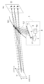
- FIG. 3 is a perspective view of a configuration example of the light guide member 5.
- the light guide member 5 reference will be made to the orthogonal coordinates of the three axes of XYZ shown in FIG.
- the light guide member 5 includes a main body portion 50, an entrance region 51, an auxiliary expansion region 52, and an output expansion region 53.
- the main body portion 50 is made of a material that is transparent in the visible light region.
- the main body portion 50 is plate-shaped. In this embodiment, the main body portion 50 has a rectangular plate shape.
- the main body 50 has a first surface 50a and a second surface 50b in the thickness direction of the main body 50.
- the thickness direction of the main body portion 50 is the Z-axis direction in FIG.
- the main body portion 50 is arranged with the first surface 50a facing the display element 2 side and the second surface 50b facing the viewing area Ac side.
- the first surface 50a is an entrance surface through which the image light L1 enters the main body 50
- the second surface 50b is an exit surface through which the image light L2 exits from the main body 50.
- the light guiding member 5 is positioned so as to guide the image light L2 emitted from the main body 50 to the viewing area Ac as a virtual image Iv by reflecting it with a light-transmitting member. This allows the user D to see the virtual image Iv superimposed on the real scene that is visible through the light-transmitting member from the viewing area Ac.
- the light-transmitting member is the windshield 101, but the light-transmitting member is not limited to the windshield 101, but may also be a combiner or the like that is transparent in the visible light region (but is not limited to being colorless and transparent). It may be a member.
- FIG. 4 is a plan view of the light guide member 5 viewed from the second surface 50b side. As shown in FIG. 4 , the entrance region 51 , the auxiliary expansion region 52 , and the output expansion region 53 are formed in the main body portion 50 of the light guide member 5 .
- the incident region 51 allows the image light L1 to enter the main body 50 so that the image light L1 propagates within the main body 50.
- the incident region 51 transmits the image light L1 incident on the first surface 50a of the main body section 50 from a first oblique direction that is inclined with respect to the normal to the first surface 50a of the main body section 50. is made to enter the main body part 50 so that it propagates within the main body part 50.
- the first inclination direction is the direction indicated by D1 in FIG.
- the incident region 51 allows the image light L1 to propagate within the main body 50 in a predetermined direction (positive direction of the X axis) orthogonal to the thickness direction of the main body 50. 50. In FIG.
- the image light propagating in the positive direction of the X-axis is labeled L1A. That is, the incident area 51 changes the traveling direction of the image light L1 that has entered the incident area 51, and causes the image light L1A to propagate in the main body 50 in a predetermined direction.
- the incident region 51 is used for coupling between the display element 2 and the light guide member 5.
- the incident region 51 allows the image light L1 to enter the main body 50 so that the image light L1 propagates within the main body 50 under total internal reflection conditions.
- "Coupling” here refers to a state in which light propagates within the main body portion 50 of the light guide member 5 under total reflection conditions.
- the incident region 51 is composed of a diffraction structure (periodic structure) that has a diffraction effect on the image light L1.
- the diffraction structure of the incident region 51 is, for example, a volume hologram element (holographic diffraction grating).
- the incident region 51 is formed inside the main body portion 50, for example.
- FIG. 5 is a schematic explanatory diagram of a volume hologram element.
- a volume hologram element generates a diffraction effect through periodic modulation of the refractive index.
- the direction of the Z1 axis is the thickness direction of the volume hologram element.
- the direction of the X1 axis and the direction of the Y1 axis are perpendicular to the direction of the Z1 axis and are also perpendicular to each other.
- the direction of the X1 axis is the direction in which the refractive index of the volume hologram element does not change.
- the direction of the Y1 axis is the direction in which the refractive index of the volume hologram element changes periodically. Gp in FIG.
- the diffraction period of the volume hologram element indicates the period of change in the refractive index of the volume hologram element.
- the diffraction period of the volume hologram element can be defined, for example, by the distance between the maximum or minimum refractive indices of the volume hologram element.
- the diffraction period of the volume hologram element in the incidence region 51 is represented by Gp1
- the X1 axis, Y1 axis, and Z1 axis of the volume hologram element in the incidence region 51 are represented by the X11 axis, Y11 axis, and Z11 axis, respectively.
- the direction of the X11 axis (the direction in which the refractive index does not change) of the volume hologram element in the incident region 51 intersects with the direction of the Y axis at an angle Ga1 in a plane (in the XY plane) perpendicular to the thickness direction of the main body 50. do.
- the incident region 51 allows the image light L1 to enter the main body portion 50 under the condition that it is totally reflected onto the first surface 50a and the second surface 50b due to the diffraction effect.
- the image light L1 travels in the positive direction of the X-axis through the incident region 51 by being totally reflected in the main body 50 by the first surface 50a and the second surface 50b.
- the size of the incident area 51 is set so that part or all of the image light L1 from the display element 2 that has passed through the projection optical system 6 is incident on the incident area 51.
- the incident region 51 has a rectangular shape.
- the auxiliary expansion region 52 is arranged in line with the incident region 51 in a predetermined direction (positive direction of the X-axis).
- the auxiliary expansion region 52 is composed of a diffraction structure (periodic structure) that has a diffraction effect on the image light L1A.
- the diffraction structure of the auxiliary expansion region 52 is, for example, a volume hologram element (holographic diffraction grating).
- the auxiliary expansion region 52 is formed inside the main body portion 50, for example. In FIG.
- the diffraction period of the volume hologram element in the auxiliary expansion region 52 is represented by Gp2
- the X1 axis, Y1 axis, and Z1 axis of the volume hologram element in the auxiliary expansion region 52 are represented by the X12 axis, Y12 axis, and Z12 axis, respectively.
- the direction of the X1 axis (the direction in which the refractive index does not change) of the volume hologram element in the auxiliary expansion region 52 is at an angle Ga2 with respect to the Y axis in a plane (in the XY plane) perpendicular to the thickness direction of the main body 50. intersect.
- the auxiliary expansion region 52 changes the traveling direction of the image light L1A to the first propagation direction and divides it into a plurality of parts.
- the first propagation direction is a direction intersecting a predetermined direction in a plane (in the XY plane) perpendicular to the thickness direction of the main body portion 50 .
- the first propagation direction is the positive direction of the Y-axis.
- the image light propagating in the positive direction of the Y-axis is labeled L1B.
- the auxiliary expansion region 52 is configured to divide the image light L1A propagating in a predetermined direction into a plurality of image lights L1B propagating in the first propagation direction in a predetermined direction.
- the auxiliary expansion region 52 directs a plurality of image lights L1B aligned in a predetermined direction (positive direction of the X-axis) toward the output expansion region 53 by dividing the image light L1A propagating within the main body 50 of the light guide member 5. .
- the auxiliary expansion region 52 expands the pupil of the image light L1 in a predetermined direction (the positive direction of the X-axis). That is, as shown in FIG. 4, the auxiliary expansion area 52 divides the image light L1A into a plurality of substantially parallel image beams L1B directed toward the output expansion area 53, so that the image light L1 projected by the projection optical system 6 is The pupil is duplicated and expanded in a predetermined direction (positive direction of the X-axis).
- the size of the auxiliary expansion area 52 is set so that the image light L1A from the incident area 51 enters the auxiliary expansion area 52.
- the dimension in the Y-axis direction of the end of the auxiliary expansion region 52 on the side of the entrance region 51 (the right end in FIG. 4) is such that the image light L1A diffracted by the entrance region 51 enters the auxiliary expansion region 52 without omission.
- the auxiliary expansion region 52 has a rectangular shape.
- the output expansion region 53 is arranged in line with the auxiliary expansion region 52 in the first propagation direction (positive direction of the Y-axis).
- the output expansion region 53 is composed of a diffraction structure (periodic structure) that has a diffraction effect on the image light L1B.
- the diffraction structure of the output expansion region 53 is, for example, a volume hologram element (holographic diffraction grating). In FIG.
- the diffraction period of the volume hologram element in the output expansion area 53 is represented by Gp3
- the X1 axis, Y1 axis, and Z1 axis of the volume hologram element in the output expansion area 53 are represented by the X13 axis, Y13 axis, and Z13 axis, respectively.
- the direction of the X1 axis (direction in which the refractive index does not change) of the volume hologram element of the output expansion region 53 is at an angle Ga3 with respect to the direction of the Y axis in a plane (in the XY plane) perpendicular to the thickness direction of the main body 50. intersect.
- the output expansion region 53 changes the traveling direction of the image light L1B to the second propagation direction and divides the image light L1B into a plurality of light beams.
- the second propagation direction is the direction from the main body 50 toward the viewing area Ac.
- the image light propagating in the second propagation direction is labeled L1C.
- the output expansion region 53 outputs the plurality of image lights L1C propagating in the second propagation direction from the second surface 50b of the main body 50 in a second inclined direction inclined with respect to the normal to the second surface 50b of the main body 50.
- the symbol L2 is attached to the image light propagating in the second oblique direction.
- the second inclination direction is the direction indicated by D1 in FIG.
- the output expansion region 53 converts the image light L1B propagating in the first propagation direction into a plurality of image lights propagating in the second propagation direction and emitting from the second surface 50b of the main body 50 in the second inclined direction.
- L2 is configured to split in a first propagation direction.
- the output expansion region 53 directs a plurality of image lights L2 lined up in the first propagation direction (positive direction of the Y-axis) toward the viewing area Ac by dividing the image light L1B propagating within the main body 50 of the light guide member 5. Dodge. In this way, the output expansion region 53 expands the pupil of the image light L1 in the first propagation direction (positive direction of the Y-axis).
- the output expansion region 53 divides the image light L1B into a plurality of substantially parallel image lights L2 directed toward the viewing area Ac, so that the image light L1 projected by the projection optical system 6 can be transmitted to the pupil of the image light L1. is duplicated and expanded in the first propagation direction (positive direction of the Y axis).
- the auxiliary expansion region 52 and the output expansion region 53 divide the image light L1 that has entered the main body 50 of the light guide member 5 from the entrance region 51, thereby replicating and expanding the pupil of the image light L1.
- the auxiliary expansion area 52 and the output expansion area 53 divide the image light L1 that has entered the main body 50 of the light guide member 5 from the entrance area 51 into a plurality of image lights L2, and divide the image light L1 into a plurality of image lights L2.
- the pupil of the image light L1 is duplicated and expanded.
- the plurality of image lights L2 reaching the viewing area Ac are preferably parallel to each other.
- the plurality of image lights L2 are parallel to each other does not necessarily mean that the plurality of image lights L2 are parallel to each other in a strict sense, but also includes that the plurality of image lights L2 are substantially parallel to each other. .
- the plurality of image lights L2 do not have to be parallel to each other in the strict sense, but it is sufficient that the directions of the plurality of image lights L2 are aligned to the extent that the plurality of image lights L2 can be considered to be parallel in terms of optical design. Since the plurality of image lights L2 are parallel to each other, it is possible to improve the uniformity of the arrangement of the pupils of the image light in the viewing area Ac, thereby reducing the omission of the pupils of the image light in the viewing area Ac.
- the plurality of image lights L2 are reflected by the windshield 101 and directed toward the viewing area Ac.
- the light guide member 5 is preferably configured so that the plurality of image lights L2 reflected by the windshield 101 and directed toward the viewing area Ac are parallel to each other.
- the incident angle and reflection angle of the image light L2 differ depending on the location within the plane of the windshield 101 even if the directions toward the windshield 101 are the same. Therefore, the light guiding member 5 is not necessarily parallel to each other until the plurality of image lights L2 are emitted from the light guiding member 5 and entering the windshield 101, but become parallel to each other by being reflected by the windshield 101. It is composed as follows.
- the light guide member 5 may be configured such that a plurality of mutually parallel image lights L2 are emitted from the light guide member 5.
- the projection optical system 6 projects image light L1 that forms an image output from the display element 2. Thereby, the projection optical system 6 allows the image light L1 from the display element 2 to enter the light guide member 5. As shown in FIG. 1, the projection optical system 6 is located between the display element 2 and the light guide member 5. The projection optical system 6, for example, collimates the image light L1 from the display element 2 and makes it enter the incident area 51. The projection optical system 6 makes the image light L1 enter the incident region 51 as substantially collimated light.
- the projection optical system 6 is, for example, a biconvex lens.
- the control device 4 can be realized using a semiconductor device or the like.
- the control device 4 can be configured with, for example, a microcomputer, CPU, MPU, GPU, DSP, FPGA, or ASIC.
- the control device 4 realizes predetermined functions by reading data and programs stored in the storage device 4a and performing various arithmetic operations.
- the storage device 4a is a storage medium that stores programs and data necessary for realizing the functions of the control device 4.
- the storage device 4a can be realized by, for example, a hard disk (HDD), SSD, RAM, DRAM, ferroelectric memory, flash memory, magnetic disk, or a combination thereof.
- the storage device 4a stores a plurality of image data representing a virtual image Iv as an optical image.
- the control device 4 determines the virtual image Iv to be displayed based on vehicle-related information acquired from the outside.
- the control device 4 reads the image data of the determined virtual image Iv from the storage device 4a and outputs it to the display element 2.
- the light guiding member 5 has at least a portion of the output extension region 53 serving as a medium on the incident side of the image light to the output extension region 53 and a medium on the output side of the image light to the output extension region 53.
- ⁇ _out is 15° or more and 45° or less
- ⁇ _in is configured to satisfy the relationship that ⁇ _out is 14° or more larger than ⁇ _out.
- ⁇ _in is the incident angle of the image light L1B that enters the output expansion area 53 on a predetermined plane P1 that includes the normal line N1 of the output expansion area 53.
- ⁇ _out is the output angle of the image light L1C that is output from the output expansion region 53 with the highest diffraction efficiency in the predetermined plane P1 including the normal N1 of the output expansion region 53.
- the light guide member 5 is configured to satisfy the following formula (1).
- the output extension region 53 has the same refractive index as the medium on the input side of the image light with respect to the output extension region 53 and the medium on the output side of the image light with respect to the output extension region 53; Furthermore, by satisfying equation (1), it is possible to reduce the generation of unnecessary diffracted light (hereinafter also simply referred to as unnecessary light) in the output expansion region 53. Thereby, the utilization efficiency of the image light L1 from the display element 2 can be improved.
- the output expansion area 53 may be any part of the output expansion area 53, but the incidence area of the output expansion area 53 is on the optical path of the image light L1 from the input area 51 to the output expansion area 53. It is good if it is included in the end on the 51 side.
- the optical path of the image light L1 from the entrance region 51 to the output extension region 53 passes through the auxiliary extension region 52. Therefore, for example, in FIG. It is not the end on the negative direction side but the end on the negative direction side of the Y axis.
- the end of the output expansion region 53 on the entrance region 51 side is a region that occupies 1/4 of the output expansion region 53 in the first propagation direction from the end 53a of the output expansion region 53 on the entrance region 51 side. It's good to be there.
- the end of the output expansion area 53 on the input area 51 side is the end of the output expansion area 53 on the side where the image light enters.
- the extension region 53 is a portion where the amount of image light L1B incident on the output extension region 53 is large.
- the refractive index of the medium on the incident side of the image light to the output expansion area 53 and the medium on the output side of the image light to the output expansion area 53 are equal in the entire output expansion area 53. In some cases, it may be configured to satisfy equation (1).
- Table 1 below shows the lower limit of the incident angle ⁇ _in that satisfies equation (1).
- the incident angle ⁇ _in is a value rounded to the nearest whole number.
- FIG. 6 is a graph showing an example of the relationship between the incident angle ⁇ _in and the output angle ⁇ _out.
- R1 indicates the relationship in Table 1
- the light guide member 5 is configured to satisfy the following formula (2).
- the incident angle ⁇ _in is a value rounded off to the nearest whole number.
- the output extension region 53 has the same refractive index as the medium on the input side of the image light with respect to the output extension region 53 and the medium on the output side of the image light with respect to the output extension region 53. Furthermore, by satisfying equation (2), the generation of unnecessary light in the output expansion region 53 can be reduced. Thereby, the utilization efficiency of the image light L1 from the display element 2 can be improved.
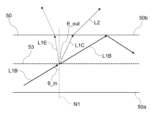
- FIG. 7 is an explanatory diagram of the diffraction effect of the image light L1B by the output expansion region 53 of the light guide member 5.
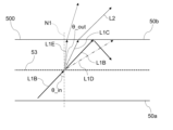
- FIG. 8 is an explanatory diagram of the diffraction effect of image light by the output expansion region 53 of the light guide member 500 of a comparative example. Diffraction by the output expansion region 53 is expressed by the following equation (3).
- m is the diffraction order.
- d is the diffraction pitch (diffraction period).
- ⁇ is the wavelength of the image light L1B.
- ⁇ m is an output angle of m-th order diffracted image light (m-th order diffracted light) exiting from the output expansion area 53 in a predetermined plane P1 including the normal line N1 of the output expansion area 53.
- n_in is the refractive index of the medium on the incident side of the image light with respect to the output expansion region 53.
- n_out is the refractive index of the medium on the output side of the image light with respect to the output expansion region 53.
- the medium on the incident side of the image light to the output expansion area 53 and the medium on the output side of the image light to the output expansion area 53 are both the main body portion 50 of the light guide member 5 .
- the refractive index n_in and the refractive index n_out are equal. Therefore, if the refractive index of the main body portion 50 of the light guide member 5 is n0 , the following equation (4) can be obtained from the above equation (3).
- the output expansion region 53 produces image light L1C, L1D, and L1E that travel in different directions from the image light L1B.
- the image light L1C is first-order diffracted light
- the image light L1D is -1st-order diffracted light
- the image light L1E is second-order diffracted light.
- the image light L1B on the output side with respect to the output expansion region 53 is zero-order diffracted light.
- the image light L1D does not exist is that the image light L1D does not exist on the output side with respect to the output extension region 53, and this is synonymous with the absence of ⁇ ⁇ 1 . From the above, the condition that the image light L1D does not exist is given by the following equation (7).
- the output angle sin ⁇ _out is set to sin ⁇ _out1
- the output angle of the image light to the output expansion area 53 is set as sin ⁇ _out1.
- the light guide member 500 of the comparative example in FIG. 8 has the same configuration as the light guide member 5 in FIG. (1) is not satisfied. Therefore, in the light guide member 500 of the comparative example, the image light L1D is present. The presence of the image light L1D reduces the amount of the image light L1C, which may be a factor in reducing the utilization efficiency of the image light L1 from the display element 2.
- FIG. 9 is a graph showing an example of the relationship between the incident angle ( ⁇ _in) of the image light L1B into the output expansion region 53 and the ratio of the -1st order diffracted light (image light L1D).
- the incident angle was 43°
- the proportion of first-order diffracted light was 18%
- the proportion of ⁇ 1st-order diffracted light was 10%
- the proportion of second-order diffracted light was 0.6%.
- the incident angle was 51°
- the proportion of first-order diffracted light was 22%
- the proportion of ⁇ 1st-order diffracted light was 0%
- the proportion of second-order diffracted light was 0.2%.
- image light L1D the proportion of the first order diffracted light (image light L1C), that is, the amount of light increases. This can be expected to improve the utilization efficiency of the image light L1 from the display element 2.
- the diffraction efficiency due to the diffraction structure of the output expansion region 53 can vary depending on the diffraction pitch (diffraction period Gp3) and the polarization state of the image light.
- FIG. 10 is a graph showing an example of the relationship between diffraction pitch and diffraction efficiency.
- Graph F1 in FIG. 10 shows changes in the maximum value of diffraction efficiency depending on the diffraction pitch when the polarization state of image light is changed.
- Graph F2 in FIG. 10 shows a change in the minimum value of diffraction efficiency depending on the diffraction pitch when the polarization state of image light is changed.
- the incident angle of the image light to the output expansion region 53 is 45°, and the wavelength of the image light is 0.52 ⁇ m.
- the diffraction structure of the output expansion region 53 is a volume hologram element, and this volume hologram element has a thickness of 5 ⁇ m, a refractive index of 1.505, and a refractive index modulation amount of 0.03.
- both the maximum and minimum values of the diffraction efficiency become large when the diffraction pitch is in the range of 1.4 ⁇ m to 2.0 ⁇ m.
- the difference between the maximum value and the minimum value of diffraction efficiency increases rapidly.
- An increase in the difference between the maximum value and the minimum value of the diffraction efficiency leads to an increase in the change in the diffraction efficiency during the propagation of the image light through the exit extension region 53, which contributes to a decrease in the image quality of the virtual image Iv. . This is because in pupil dilation, any image light is accompanied by a change in the polarization state due to the diffraction structure.
- the output expansion If the diffraction period of the region 53 is 1.23 ⁇ /n or more and 10.0 ⁇ /n or less, the difference between the maximum value and the minimum value of the diffraction efficiency can be reduced, but the difference between the maximum value and the minimum value of the diffraction efficiency can be reduced. It was confirmed that the minimum value could be increased.
- the utilization efficiency of the image light L1 from the display element 2 can be improved, and deterioration in the image quality of the virtual image Iv due to the polarization state of the image light L1 can be reduced.
- ⁇ is the wavelength of the image light
- n is the refractive index of the output expansion region 53.
- the refractive index of the output expansion region 53 is the refractive index of the volume hologram element when the diffraction structure of the output expansion region 53 is a volume hologram element.
- Tables 2 to 4 below show image light parameters and diffraction structure parameters regarding the entrance region 51, auxiliary extension region 52, and output extension region 53 of Examples 1 to 4 and Comparative Examples 1 to 3, respectively.
- the parameters of the image light regarding the entrance region 51, the auxiliary expansion region 52, and the output expansion region 53 include ⁇ _inx [°], ⁇ _iny [°], ⁇ _outx [°], and ⁇ _outy [°].
- ⁇ _inx is the incident angle of the image light on the XZ plane of the light guide member 5 in FIG. 3.
- ⁇ _outx is the output angle of the image light in the XZ plane of the light guide member 5.
- FIG. 11 is an explanatory diagram of the incident angle ⁇ _inx and the output angle ⁇ _outx of the image light in the XZ plane of the light guide member 5 of FIG. 3.
- the diffraction structure 54 indicates the diffraction structure of the entrance region 51, the auxiliary extension region 52, or the output extension region 53.
- Image light L11 indicates image light that enters the incident area 51, the auxiliary expansion area 52, or the output expansion area 53.
- Image light L12 indicates image light that is emitted from the entrance region 51, the auxiliary extension region 52, or the output extension region 53 with the highest diffraction efficiency.
- ⁇ _inx is the incident angle of the image light L11 incident on the diffraction structure 54 in a predetermined plane (XZ plane) including the normal N2 of the diffraction structure 54.
- ⁇ _outx is the output angle of the image light L12 that is output from the diffraction structure 54 with the highest diffraction efficiency in a predetermined plane (XZ plane) including the normal line N2 of the diffraction structure 54.
- ⁇ _iny is the incident angle of the image light on the YZ plane of the light guide member 5 in FIG. 3.
- ⁇ _outy is the emission angle of the image light in the YZ plane of the light guide member 5.
- FIG. 12 is an explanatory diagram of the incident angle ⁇ _iny and the output angle ⁇ _outy of the image light in the YZ plane of the light guide member 5 of FIG.
- the diffraction structure 54 indicates the diffraction structure of the entrance region 51, the auxiliary extension region 52, or the output extension region 53.
- Image light L11 indicates image light that enters the incident area 51, the auxiliary expansion area 52, or the output expansion area 53.
- Image light L12 indicates image light that is emitted from the entrance region 51, the auxiliary extension region 52, or the output extension region 53 with the highest diffraction efficiency.
- ⁇ _iny is the incident angle of the image light L11 that enters the diffraction structure 54 in a predetermined plane (YZ plane) including the normal N2 of the diffraction structure 54.
- ⁇ _outy is the output angle of the image light L12 that is output from the diffraction structure 54 with the highest diffraction efficiency in a predetermined plane (YZ plane) including the normal line N2 of the diffraction structure 54.
- the parameters of the diffraction structure regarding the incident region 51 include Ga1 [°] and Gp1 [ ⁇ m] shown in FIG.
- the parameters of the diffraction structure regarding the auxiliary expansion region 52 include Ga2 [°] and Gp2 [ ⁇ m] shown in FIG.
- the parameters of the diffraction structure regarding the output expansion region 53 include Ga3 [°] and Gp3 [ ⁇ m] shown in FIG.
- Table 5 below shows the left and right sides of formula (1) and the presence or absence of unnecessary light for Examples 1 to 4 and Comparative Examples 1 to 3.
- the left and right sides of equation (1) in Table 5 are calculated by substituting ⁇ _iny in Table 4 as ⁇ _in in equation (1) and substituting ⁇ _outy in Table 4 as ⁇ _out in equation (1).
- the refractive index n of the main body portion 50 of the light guide member 5 is 1.505.
- the wavelength of the image light L1 is 0.52 [ ⁇ m].
- Example 2 and Comparative Example 2 the wavelength of the image light L1 is 0.62 [ ⁇ m].
- Examples 1 to 4 satisfy formula (1), and Comparative Examples 1 to 3 do not satisfy formula (1). Therefore, by at least a portion of the output expansion region 53 satisfying the following formula (1), the generation of unnecessary light in the output expansion region 53 can be reduced. Thereby, the utilization efficiency of the image light L1 from the display element 2 can be improved.
- the output angle ⁇ _outy of the image light on the YZ plane of the light guide member 5 is 15° or more and 45° or less
- the incident angle ⁇ _iny of the image light on the YZ plane of the light guide member 5 is: It is 14° or more larger than the output angle ⁇ _outy.
- Examples 1 to 3 satisfy formula (2).
- the first inclination angle and the second inclination angle of the image light L1 are not 0° and are suitable for a head-up display, and in Example 4, the first inclination angle and the second inclination angle of the image light L1 are The tilt angle is 0°, making it suitable for head-mounted displays.
- the optical system 3 described above includes a light guide member 5 that guides the image light L1 that forms an image output from the display element 2 to the viewing area Ac of the user D as an optical image (virtual image Iv).
- the light guide member 5 includes a plate-shaped main body 50, an incident region 51 formed on the main body 50 and allowing the image light L1 to enter the main body 50 so that the image light L1 propagates within the main body 50.
- Image light L1B formed in the main body 50 and propagating in a first propagation direction intersecting the thickness direction of the main body 50 is converted into a plurality of image lights L1C propagating in a second propagation direction intersecting the first propagation direction.
- an output expansion region 53 having a diffraction structure that is divided in one propagation direction and output from the light guide member 5. At least a portion of the output expansion area 53 is formed by the output expansion area 53 when the refractive index of the medium on the incident side of the image light with respect to the output expansion area 53 and the medium on the output side of the image light with respect to the output expansion area 53 are equal.
- the output angle ⁇ _out of the image light L1C that is outputted with the highest diffraction efficiency from the output extension region 53 in the predetermined plane P1 including the normal N of is 15° or more and 45° or less, and
- the incident angle ⁇ _in of the image light L1B is greater than the output angle ⁇ _out by 14° or more. This configuration can improve the utilization efficiency of the image light L1 from the display element 2.
- This configuration can improve the utilization efficiency of the image light L1 from the display element 2.
- This configuration can improve the utilization efficiency of the image light L1 from the display element 2.
- the main body portion 50 has a first surface 50a and a second surface 50b in the thickness direction.
- the incident area 51 is configured to direct image light L1 incident on the first surface 50a from a first oblique direction inclined with respect to the normal to the first surface 50a into the main body 50 so that the image light L1 propagates within the main body 50. Inject it into the
- the output expansion region 53 causes the plurality of image lights L1C propagating in the second propagation direction to be output from the second surface 50b in a second inclined direction inclined with respect to the normal line of the second surface 50b. This configuration can improve the utilization efficiency of the image light L1 from the display element 2.
- the first tilt direction and the second tilt direction are parallel to each other. This configuration can improve the utilization efficiency of the image light L1 from the display element 2.
- the diffraction structure of the output expansion region 53 is a volume hologram element located inside the main body 50. With this configuration, the size of the output expansion region 53 can be easily increased.
- the light guide member 5 is formed in the main body 50, and converts the image light L1A propagating in a predetermined direction within the main body 50 into a plurality of image lights L1B propagating in the first propagation direction through the incident region 51.
- the light guide member 5 further includes an auxiliary expansion region 52 having a diffraction structure that is divided in a predetermined direction and directed toward the output expansion region 53 . This configuration allows dilation of the pupil in multiple different directions.
- the diffraction pitch of the output expansion region 53 is greater than or equal to 1.23 ⁇ /n and less than or equal to 10.0 ⁇ /n.
- ⁇ is the wavelength of the image light L1, L1A, L1B, L1C, and L2.
- n is the refractive index of the output expansion region 53.
- At least a portion of the output expansion area 53 is included in the end of the output expansion area 53 on the input area 51 side on the optical path of the image light L1 from the input area 51 to the output expansion area 53. This configuration can improve the utilization efficiency of the image light L1 from the display element 2.
- the light guide member 5 is positioned so as to guide the image light L2 emitted from the main body 50 to the viewing area Ac as an optical image (virtual image Iv) by reflecting it on a light-transmitting member (windshield 101). do.
- This configuration can be used as a head-up display.
- the optical system 3 further includes a projection optical system 6 that makes the image light L1 enter the incident area 51 of the light guide member 5 as substantially collimated light. This configuration can further improve the utilization efficiency of the image light L1 from the display element 2.
- the image display device 1 described above includes an optical system 3 and a display element 2. This configuration can improve the utilization efficiency of the image light L1 from the display element 2.
- Embodiments of the present disclosure are not limited to the above embodiments.
- the embodiments described above can be modified in various ways depending on the design, etc., as long as the objects of the present disclosure can be achieved. Modifications of the above embodiment are listed below.
- the modified examples described below can be applied in combination as appropriate.
- the diffraction structure of the output expansion region 53 is not limited to a volume hologram element (holographic diffraction grating), but may be a surface relief type diffraction grating.
- the surface relief type diffraction grating is a reflective type
- the medium on the incident side of the image light to the output expansion area 53 and the medium on the output side of the image light to the output expansion area 53 are both the main body part of the light guide member 5. It is 50.
- the surface relief type diffraction grating is a transmission type
- the medium on the incident side of the image light to the output extension region 53 is the main body portion 50 of the light guide member 5;
- the medium is, for example, air.
- the output extension area 53 has a medium on the incident side of the image light to the output extension area 53 and a medium on the output side of the image light to the output extension area 53. If it is assumed that the refractive indexes of the medium and the refractive index are the same, then equation (1) may be satisfied.
- FIG. 13 is a schematic explanatory diagram of a surface relief type diffraction grating.
- the surface relief type diffraction grating of FIG. 13 is of a reflective type.
- the surface relief type diffraction grating generates a diffraction effect in the periodically arranged uneven portions 55.
- the uneven portion 55 in FIG. 13 is a groove.
- the direction of the Z2 axis is the thickness direction of the surface relief type diffraction grating.
- the direction of the X2 axis and the direction of the Y2 axis are perpendicular to the direction of the Z2 axis and are also perpendicular to each other.
- the direction of the X2 axis is the direction in which the uneven portion 55 extends.
- the direction of the Y2 axis is the direction in which the uneven portions 55 are lined up.
- Gp in FIG. 13 indicates the diffraction period (diffraction pitch) [ ⁇ m] of the surface relief type diffraction grating.
- the diffraction period Gp3 of the output expansion region 53 in FIG. 4 may correspond to the diffraction period Gp in FIG. 13.
- the angle Ga3 of the output expansion region 53 in FIG. 4 is the angle in the X2-axis direction of the surface relief type diffraction grating in FIG. may correspond to
- the surface relief type diffraction grating is not limited to the same material as the light guide member 5, and may be formed of a different material.
- the material of the light guide member 5 may be glass, and the material of the surface relief type diffraction grating may be an ultraviolet curing resin.
- a surface relief type diffraction grating can be formed by nanoimprint technology. Note that, when the diffraction structure of the output expansion region 53 is a surface relief type diffraction grating, the refractive index of the output expansion area 53 is the refractive index of the material forming the surface relief type diffraction grating.
- the diffraction structures of the incident region 51 and the auxiliary expansion region 52 are not limited to volume hologram elements (holographic diffraction gratings), but may be surface relief type diffraction gratings.
- the entrance region 51 and the auxiliary extension region 52 may have a half mirror.
- the light guide member 5 does not need to include the auxiliary expansion region 52.
- the light guide member 5 may be configured to perform pupil dilation in one axis instead of two.
- the incident area 51 changes the traveling direction of the image light L1 that has entered the incident area 51, and causes the image light L1 to propagate in the main body 50 in the first propagation direction.
- the output expansion region 53 may divide the image light L1B from the incident region 51 into a plurality of image lights L1C propagating in the second propagation direction in the first propagation direction and emit the divided image light L1C from the light guide member 5.
- the diffraction pitch of the output expansion region 53 is greater than or equal to 1.36 ⁇ /n and less than or equal to 3.82 ⁇ /n.
- ⁇ is the wavelength of the image light L1.
- n is the refractive index of the main body portion 50.
- the range of the incident angle ⁇ _in that is 14 degrees or more larger than the output angle ⁇ _out or that satisfies equation (1) covers both outer edges of the image light L1B incident on the output expansion region 53 with respect to the predetermined plane P1. Includes the range determined by the incident angle of the specified secondary ray.
- the image light L1B often has a certain degree of spread, and the principal ray and sub rays of the image light L1B may have different angles of incidence on the output expansion region 53.
- the range of the incident angle ⁇ _in that is 14 degrees or more larger than the output angle ⁇ _out or that satisfies equation (1) is the incident angle of the sub-ray that defines both outer edges of the image light L1B that enters the output expansion region 53 with respect to the predetermined plane P1.
- the light guide member 5 does not necessarily guide the image light L2 emitted from the main body 50 to the viewing area Ac as an optical image (virtual image Iv) by reflecting it on a light-transmitting member (windshield 101). It does not have to be located in
- the light guide member 5 may be positioned so as to be aligned with the viewing area Ac. That is, the optical path from the light guide member 5 to the viewing area Ac may be a straight line.
- the projection optical system 6 may include a first optical element and a second optical element as a plurality of optical elements instead of a single optical element.
- the first optical element is, for example, a cemented lens that is a combination of a negative meniscus lens and a biconvex lens
- the second optical element is a cemented lens that is a combination of a positive meniscus lens and a negative meniscus lens. Note that the optical system 3 does not need to include the projection optical system 6.
- the projection optical system 6 and the incident area 51 do not necessarily need to be aligned in a straight line. That is, the optical path of the image light L1 from the projection optical system 6 to the incident area 51 is not necessarily a straight line.
- the image light L1 from the projection optical system 6 may be reflected by a reflector and made to enter the incident area 51.
- the optical path of the image light L1 from the projection optical system 6 to the incident area 51 is not linear but, for example, L-shaped.
- the image display device 1 may include a plurality of light guide members 5 each corresponding to a wavelength of light included in the image light L1. This allows a color image to be provided to the user.
- the image display device 1 is not limited to a head-up display used in a car, but can also be applied to moving objects other than cars, such as motorcycles, trains, aircraft, construction machinery, and ships. Furthermore, the image display device 1 is not limited to a mobile object, and may be used in an amusement facility, for example, or as a wearable terminal such as a head mounted display (HMD), medical equipment, or a stationary device. may be used.
- HMD head mounted display
- a stationary device may be used.
- the display element 2 and optical system 3 that make the virtual image Iv visible as an example of an optical image have been described.
- the optical image displayed by the display element 2 is not limited to the virtual image Iv, but may be a real image, for example.
- the display element 2 may be configured such that a real image is formed between the user D and a light-transmissive member such as the windshield 101 using the pupil expansion type optical system 3 similar to that described above. Displaying such a real image is useful, for example, in amusement applications. Even when such a real image is visually recognized as an optical image, the influence of polarized light in the light guide member 5 on brightness unevenness is considered as in the case of the virtual image Iv described above.
- variations in the image quality of a real image can be suppressed by suppressing brightness unevenness by controlling the polarization state as in each of the above embodiments.
- the first aspect is an optical system (3) that transmits image light (L1) forming an image output from a display element (2) to an optical image (virtual image Iv) in a visual field (Ac) of a user (D). ) is provided.
- the light guide member (5) is formed on a plate-shaped main body (50) and the main body (50), and is configured to guide the image so that the image light (L1) propagates within the main body (50).
- the image light (L1B) is divided in the first propagation direction into a plurality of image lights (L1C) that propagate in a second propagation direction intersecting the first propagation direction, and the split images are emitted from the light guide member (5).
- an output expansion region (53) having a diffraction structure that causes At least a portion of the output expansion area (53) is formed of a medium on the incident side of the image light (L1B) with respect to the output expansion area (53) and a medium on the output side of the image light (L1B) with respect to the output expansion area (53).
- the beam exits from the exit extension region (53) with the highest diffraction efficiency in a predetermined plane (P1) including the normal (N) of the exit extension region (53).
- the output angle ⁇ _out of the image light (L1C) is 15° or more and 45° or less, and the incident angle ⁇ _in of the image light (LIB) entering the output expansion area (53) in the predetermined plane (P1) is It is 14° or more larger than the output angle ⁇ _out. This aspect can improve the utilization efficiency of the image light (L1) from the display element (2).
- the second aspect is an optical system (3) based on the first aspect.
- the following formula (1) is satisfied.
- This aspect can improve the utilization efficiency of the image light (L1) from the display element (2).
- the third aspect is an optical system (3) based on the first or second aspect.
- the following formula (2) is satisfied.
- This aspect can improve the utilization efficiency of the image light (L1) from the display element (2).
- the fourth aspect is an optical system (3) based on any one of the first to third aspects.
- the main body portion (50) has a first surface (50a) and a second surface (50b) in the thickness direction.
- the incident area (51) converts the image light (L1) that is incident on the first surface (50a) from a first inclined direction inclined with respect to the normal line of the first surface (50a) into the image light (L1). ) is made to enter the main body (50) so as to propagate within the main body (50).
- the output expansion region (53) transmits the plurality of image lights (L1C) propagating in the second propagation direction from the second surface (50b) to a second surface (50b) that is inclined with respect to the normal line of the second surface (50b). 2. Emit light in two oblique directions. This aspect can improve the utilization efficiency of the image light (L1) from the display element (2).
- the fifth aspect is an optical system (3) based on the fourth aspect.
- the first tilt direction and the second tilt direction are parallel to each other. This aspect can improve the utilization efficiency of the image light (L1) from the display element (2).
- the sixth aspect is an optical system (3) based on any one of the first to fifth aspects.
- the diffractive structure of the exit extension region (53) is a volume hologram element located inside the main body (50). This aspect allows the size of the output expansion region (53) to be easily increased.
- the seventh aspect is an optical system (3) based on any one of the first to sixth aspects.
- the light guiding member (5) is formed in the main body (50) and guides the image light (L1A) propagating in a predetermined direction within the main body (50) through the incident area (51). , further comprising an auxiliary extension region (52) having a diffraction structure that divides the plurality of image lights (L1B) propagating in the first propagation direction in the predetermined direction and directs them to the output extension region (53).
- This aspect allows dilation of the pupil in multiple different directions.
- the eighth aspect is an optical system (3) based on any one of the first to seventh aspects.
- the diffraction pitch of the output expansion region (53) is greater than or equal to 1.23 ⁇ /n and less than or equal to 10.0 ⁇ /n.
- ⁇ is the wavelength of the image light (L1, L1A, L1B, L1C, L2).
- n is the refractive index of the output expansion region (53).
- the ninth aspect is an optical system (3) based on any one of the first to eighth aspects.
- the diffraction pitch of the output expansion region (53) is greater than or equal to 1.36 ⁇ /n and less than or equal to 3.82 ⁇ /n.
- ⁇ is the wavelength of the image light (L1, L1A, L1B, L1C, L2).
- n is the refractive index of the output expansion region (53). This aspect can improve the utilization efficiency of the image light (L1) from the display element (2).
- a tenth aspect is an optical system (3) based on any one of the first to ninth aspects.
- the range of the incident angle ⁇ _in that is 14 degrees or more greater than the output angle ⁇ _out is the range of the incident angle ⁇ _in that is 14 degrees or more larger than the output angle ⁇ _out of the sub-ray that defines both outer edges of the image light incident on the output expansion region (53) with respect to the predetermined plane (P1).
- the range determined by the angle of incidence This aspect can further improve the utilization efficiency of the image light (L1) from the display element (2).
- the eleventh aspect is an optical system (3) based on any one of the first to tenth aspects.
- the at least part of the output expansion area (53) is located on the optical path of the image light (L1) from the input area (51) to the output expansion area (53). is included in the end on the incident area (51) side. This aspect can improve the utilization efficiency of the image light (L1) from the display element (2).
- the twelfth aspect is an optical system (3) based on any one of the first to eleventh aspects.
- the light guide member (5) reflects the image light (L2) emitted from the main body (50) by a light-transmitting member (windshield 101), thereby directing the image light (L2) to the viewing area (Ac). It is positioned so as to guide the optical image (virtual image Iv).
- This aspect can be used as a head-up display.
- a thirteenth aspect is an optical system (3) based on any one of the first to twelfth aspects.
- the optical system (3) further includes a projection optical system (6) that makes the image light (L1) enter the incident area (51) of the light guide member (5) as substantially collimated light. .
- This aspect can further improve the utilization efficiency of the image light (L1) from the display element (2).
- a fourteenth aspect is an image display device (1) comprising an optical system (3) based on any one of the first to thirteenth aspects and the display element (2). This aspect can improve the utilization efficiency of the image light (L1) from the display element (2).
- the present disclosure is applicable to optical systems and image display devices. Specifically, the present disclosure is applicable to an optical system for guiding image light from a display element to a user's visual field as an optical image, and an image display device including this optical system.
- Image display device 2 Display element 3 Optical system 5
- Light guide member 50 Main body 50a First surface 50b Second surface 51
- Incident region 52 Auxiliary expansion region 53
- Output expansion region 6 Projection optical system 100
- Moving body 101 Windshield (light transmittance) Element)
- Ac Visual field D
- User Iv Virtual image (optical image) L1, L1A, L1B, L1C, L2 Image light
- N Normal n Refractive index
- P1 Predetermined plane
Landscapes
- Physics & Mathematics (AREA)
- General Physics & Mathematics (AREA)
- Optics & Photonics (AREA)
- Engineering & Computer Science (AREA)
- Mechanical Engineering (AREA)
- Multimedia (AREA)
- Signal Processing (AREA)
- Optical Couplings Of Light Guides (AREA)
- Diffracting Gratings Or Hologram Optical Elements (AREA)
Priority Applications (4)
| Application Number | Priority Date | Filing Date | Title |
|---|---|---|---|
| EP23830742.5A EP4550027A4 (en) | 2022-06-29 | 2023-03-16 | OPTICAL SYSTEM AND IMAGE DISPLAY DEVICE |
| JP2024530297A JPWO2024004288A1 (https=) | 2022-06-29 | 2023-03-16 | |
| CN202380048122.5A CN119422098A (zh) | 2022-06-29 | 2023-03-16 | 光学系统以及图像显示装置 |
| US18/983,957 US20250116860A1 (en) | 2022-06-29 | 2024-12-17 | Optical system and image display device |
Applications Claiming Priority (2)
| Application Number | Priority Date | Filing Date | Title |
|---|---|---|---|
| JP2022-104938 | 2022-06-29 | ||
| JP2022104938 | 2022-06-29 |
Related Child Applications (1)
| Application Number | Title | Priority Date | Filing Date |
|---|---|---|---|
| US18/983,957 Continuation US20250116860A1 (en) | 2022-06-29 | 2024-12-17 | Optical system and image display device |
Publications (1)
| Publication Number | Publication Date |
|---|---|
| WO2024004288A1 true WO2024004288A1 (ja) | 2024-01-04 |
Family
ID=89381916
Family Applications (1)
| Application Number | Title | Priority Date | Filing Date |
|---|---|---|---|
| PCT/JP2023/010420 Ceased WO2024004288A1 (ja) | 2022-06-29 | 2023-03-16 | 光学系、及び、画像表示装置 |
Country Status (5)
| Country | Link |
|---|---|
| US (1) | US20250116860A1 (https=) |
| EP (1) | EP4550027A4 (https=) |
| JP (1) | JPWO2024004288A1 (https=) |
| CN (1) | CN119422098A (https=) |
| WO (1) | WO2024004288A1 (https=) |
Cited By (1)
| Publication number | Priority date | Publication date | Assignee | Title |
|---|---|---|---|---|
| WO2026041955A1 (en) * | 2024-08-19 | 2026-02-26 | 3M Innovative Properties Company | Optical system and optical waveguide |
Citations (4)
| Publication number | Priority date | Publication date | Assignee | Title |
|---|---|---|---|---|
| JP2002162598A (ja) * | 2000-11-28 | 2002-06-07 | Olympus Optical Co Ltd | 観察光学系および撮像光学系 |
| US20180164591A1 (en) * | 2016-12-12 | 2018-06-14 | Oculus Vr, Llc | Tiled waveguide display |
| WO2019176438A1 (ja) * | 2018-03-13 | 2019-09-19 | ソニー株式会社 | 光学装置、画像表示装置及び表示装置 |
| JP2019191313A (ja) * | 2018-04-23 | 2019-10-31 | 株式会社デンソー | ヘッドアップディスプレイ装置 |
Family Cites Families (2)
| Publication number | Priority date | Publication date | Assignee | Title |
|---|---|---|---|---|
| DE102017126908A1 (de) * | 2017-11-15 | 2019-05-16 | Carl Zeiss Ag | Lichtleiter für ein HMD, HMD und Verfahren zum Übertragen eines Bildes in einem HMD |
| JP7323623B2 (ja) * | 2018-12-27 | 2023-08-08 | ノキア テクノロジーズ オサケユイチア | ディスプレイに使用するための装置、方法及びシステム |
-
2023
- 2023-03-16 JP JP2024530297A patent/JPWO2024004288A1/ja active Pending
- 2023-03-16 EP EP23830742.5A patent/EP4550027A4/en active Pending
- 2023-03-16 CN CN202380048122.5A patent/CN119422098A/zh active Pending
- 2023-03-16 WO PCT/JP2023/010420 patent/WO2024004288A1/ja not_active Ceased
-
2024
- 2024-12-17 US US18/983,957 patent/US20250116860A1/en active Pending
Patent Citations (4)
| Publication number | Priority date | Publication date | Assignee | Title |
|---|---|---|---|---|
| JP2002162598A (ja) * | 2000-11-28 | 2002-06-07 | Olympus Optical Co Ltd | 観察光学系および撮像光学系 |
| US20180164591A1 (en) * | 2016-12-12 | 2018-06-14 | Oculus Vr, Llc | Tiled waveguide display |
| WO2019176438A1 (ja) * | 2018-03-13 | 2019-09-19 | ソニー株式会社 | 光学装置、画像表示装置及び表示装置 |
| JP2019191313A (ja) * | 2018-04-23 | 2019-10-31 | 株式会社デンソー | ヘッドアップディスプレイ装置 |
Non-Patent Citations (1)
| Title |
|---|
| See also references of EP4550027A4 * |
Cited By (1)
| Publication number | Priority date | Publication date | Assignee | Title |
|---|---|---|---|---|
| WO2026041955A1 (en) * | 2024-08-19 | 2026-02-26 | 3M Innovative Properties Company | Optical system and optical waveguide |
Also Published As
| Publication number | Publication date |
|---|---|
| CN119422098A (zh) | 2025-02-11 |
| US20250116860A1 (en) | 2025-04-10 |
| EP4550027A1 (en) | 2025-05-07 |
| EP4550027A4 (en) | 2025-09-17 |
| JPWO2024004288A1 (https=) | 2024-01-04 |
Similar Documents
| Publication | Publication Date | Title |
|---|---|---|
| CN105929535B (zh) | 图像显示装置 | |
| EP3223059B1 (en) | Light guide and display device having two reflective holographic elements | |
| EP3805843B1 (en) | Head-up display system and vehicle | |
| US20240111152A1 (en) | Image display device and headup display system | |
| US20250116860A1 (en) | Optical system and image display device | |
| JP7716673B2 (ja) | 光学系、及び、画像表示装置 | |
| WO2023188657A1 (ja) | 光学系、及び、画像表示装置 | |
| US20230393395A1 (en) | Head-up display system | |
| US20230393392A1 (en) | Head-up display system | |
| JP2022530250A (ja) | ホログラフィック導光板 | |
| EP4050401B1 (en) | Optical system and mixed reality device | |
| US20230359050A1 (en) | Low residual layer thickness waveguide with high-index coating | |
| WO2024004289A1 (ja) | 光学系、及び、画像表示装置 | |
| JP7784640B2 (ja) | 光学系及びそれを備えたヘッドアップディスプレイシステム | |
| EP4550026A1 (en) | Image display device and optical system | |
| US20240160016A1 (en) | Optical system and head-up display system comprising same | |
| US20250020916A1 (en) | Optical system and head-up display system including same | |
| JP7558841B2 (ja) | 画像投影装置 | |
| WO2023188656A1 (ja) | 光学系、及び、画像表示装置 | |
| CN117761825A (zh) | 一种光波导器件及ar显示装置 | |
| JP2023070440A (ja) | 回折素子及びそれを備えた光学系、ヘッドアップディスプレイシステム | |
| CN120693548A (zh) | 具有紧凑型衍射光学器件的图像光导 |
Legal Events
| Date | Code | Title | Description |
|---|---|---|---|
| 121 | Ep: the epo has been informed by wipo that ep was designated in this application |
Ref document number: 23830742 Country of ref document: EP Kind code of ref document: A1 |
|
| WWE | Wipo information: entry into national phase |
Ref document number: 2024530297 Country of ref document: JP |
|
| WWE | Wipo information: entry into national phase |
Ref document number: 202380048122.5 Country of ref document: CN |
|
| WWE | Wipo information: entry into national phase |
Ref document number: 2023830742 Country of ref document: EP |
|
| NENP | Non-entry into the national phase |
Ref country code: DE |
|
| ENP | Entry into the national phase |
Ref document number: 2023830742 Country of ref document: EP Effective date: 20250129 |
|
| WWP | Wipo information: published in national office |
Ref document number: 202380048122.5 Country of ref document: CN |
|
| WWP | Wipo information: published in national office |
Ref document number: 2023830742 Country of ref document: EP |