WO2023188657A1 - 光学系、及び、画像表示装置 - Google Patents
光学系、及び、画像表示装置 Download PDFInfo
- Publication number
- WO2023188657A1 WO2023188657A1 PCT/JP2022/048394 JP2022048394W WO2023188657A1 WO 2023188657 A1 WO2023188657 A1 WO 2023188657A1 JP 2022048394 W JP2022048394 W JP 2022048394W WO 2023188657 A1 WO2023188657 A1 WO 2023188657A1
- Authority
- WO
- WIPO (PCT)
- Prior art keywords
- diffraction structure
- region
- diffraction
- main body
- light
- Prior art date
Links
- 230000003287 optical effect Effects 0.000 title claims abstract description 118
- 230000008878 coupling Effects 0.000 claims abstract description 71
- 238000010168 coupling process Methods 0.000 claims abstract description 71
- 238000005859 coupling reaction Methods 0.000 claims abstract description 71
- 230000001902 propagating effect Effects 0.000 claims abstract description 54
- 230000000737 periodic effect Effects 0.000 claims description 46
- 230000010076 replication Effects 0.000 claims description 34
- 230000000007 visual effect Effects 0.000 claims description 7
- 238000012986 modification Methods 0.000 description 37
- 230000004048 modification Effects 0.000 description 37
- 210000001747 pupil Anatomy 0.000 description 18
- 238000010586 diagram Methods 0.000 description 7
- 230000000694 effects Effects 0.000 description 5
- 239000000463 material Substances 0.000 description 5
- 230000005540 biological transmission Effects 0.000 description 4
- 238000005516 engineering process Methods 0.000 description 4
- 238000004519 manufacturing process Methods 0.000 description 3
- 230000005499 meniscus Effects 0.000 description 3
- 101000679735 Saccharomyces cerevisiae (strain ATCC 204508 / S288c) 60S ribosomal protein L16-A Proteins 0.000 description 2
- 230000007423 decrease Effects 0.000 description 2
- 210000003128 head Anatomy 0.000 description 2
- 239000004973 liquid crystal related substance Substances 0.000 description 2
- 230000003362 replicative effect Effects 0.000 description 2
- 238000007792 addition Methods 0.000 description 1
- 230000014509 gene expression Effects 0.000 description 1
- 239000011521 glass Substances 0.000 description 1
- 230000010344 pupil dilation Effects 0.000 description 1
- 239000011347 resin Substances 0.000 description 1
- 229920005989 resin Polymers 0.000 description 1
- 229910052710 silicon Inorganic materials 0.000 description 1
- 239000010703 silicon Substances 0.000 description 1
- 239000007787 solid Substances 0.000 description 1
- 238000006467 substitution reaction Methods 0.000 description 1
Images


Classifications
-
- G—PHYSICS
- G02—OPTICS
- G02B—OPTICAL ELEMENTS, SYSTEMS OR APPARATUS
- G02B27/00—Optical systems or apparatus not provided for by any of the groups G02B1/00 - G02B26/00, G02B30/00
- G02B27/02—Viewing or reading apparatus
-
- G—PHYSICS
- G02—OPTICS
- G02B—OPTICAL ELEMENTS, SYSTEMS OR APPARATUS
- G02B5/00—Optical elements other than lenses
- G02B5/18—Diffraction gratings
Definitions
- the present disclosure relates to an optical system and an image display device.
- Patent Document 1 discloses a viewing optics assembly (VOA) that presents a digital or virtual image to a viewer as an image display device.
- a VOA includes a projector and an eyepiece worn by a viewer.
- the eyepiece includes multiple eyepiece layers.
- Each eyepiece layer includes a planar waveguide, a coupling grating, an orthogonal pupil extension region, and an exit pupil extension region.
- the projector illuminates the coupling grid of the eyepiece with image light.
- a coupling grating couples image light from the projector into the planar waveguide for propagation toward the orthogonal pupil expansion region.
- the planar waveguide propagates the image light in the horizontal direction by total internal reflection.
- the orthogonal pupil extension region includes a diffractive element that replicates and directs the image light from the coupling grating to the exit pupil extension region.
- the exit pupil expansion region includes a diffractive element that directs a portion of the image light propagating within the planar waveguide toward the viewer's eyes.
- Patent Document 1 discloses that in order to reduce the decrease in the amount of emitted light depending on the position, in a diffractive structure, the height or depth of the diffractive element is changed as a function of the position, thereby improving the uniformity of light. Disclose what you will do.
- the present disclosure provides an optical system and an image display device that can improve the efficiency of using image light from a display element.
- An optical system includes a light guide member that guides image light that forms an image output from a display element to a user's visual field as a virtual image.
- the light guiding member includes a plate-shaped main body, a coupling region formed on the main body for allowing the image light to enter the main body so that the image light propagates within the main body, and a coupling region formed on the main body and having a thickness of the main body. It is a surface relief type diffraction grating that divides an image light propagating in a first propagation direction intersecting the direction into a plurality of image lights propagating in a second propagation direction intersecting the first propagation direction in the first propagation direction. a duplicate region having a diffractive structure region.
- the diffractive structure region includes a first diffractive structure and a second diffractive structure opposite the coupling region with respect to the first diffractive structure in the first propagation direction.
- the grating height of the first diffractive structure is higher than the grating height of the second diffractive structure.
- the grating width of the first diffraction structure is wider than the grating width of the second diffraction structure.
- An image display device includes the above optical system and a display element.
- aspects of the present disclosure can improve the utilization efficiency of image light from the display element.
- FIG. 1 A schematic perspective view of a configuration example of an image display device according to an embodiment
- a plan view of the light guide member of the image display device in FIG. 1 A partial cross-sectional view of the light guide member of the image display device in FIG. 1
- Graph of the diffraction efficiency characteristics of the second diffraction structure in the duplicated region in Figure 3 Graph of diffraction efficiency characteristics of the third diffraction structure in the duplicated region in Figure 3
- expressions such as "to direct in the direction of XX” and “to propagate in the XX direction” with respect to light mean that the light that forms the image as a whole heads in the XX direction, and to form the image.
- the light rays included in the light may be inclined with respect to the ⁇ direction.
- “light heading in the XX direction” only needs to have its principal ray facing in the XX direction, and the secondary rays of the light may be inclined with respect to the XX direction.
- FIG. 1 is a schematic diagram of a configuration example of an image display device 1.
- the image display device 1 is, for example, a head-mounted display (HMD) that is attached to a user's head and displays images (videos).
- the image display device 1 includes a display element 2 and an optical system 3.
- the display element 2 outputs image light L1 that forms an image in order to display an image (video).
- the image light L1 is depicted as light with directivity, but in reality it enters the optical system 3 as light having an angle corresponding to the viewing angle.
- the optical axis of the display element 2 is the optical axis of the image light L1.
- the optical axis of the image light L1 is, for example, the optical axis of light output from the center of the display element 2.
- Examples of the display element 2 include known displays such as a liquid crystal display, an organic EL display, a scanning MEMS mirror, an LCOS (Liquid Crystal On Silicon), a DMD (Digital Mirror Device), and a micro LED.
- the optical system 3 guides the image light L1 output by the display element 2 to a viewing area 8 set for the user's eyes.
- the viewing area 8 the user can view the image formed by the display element 2 with his or her own eyes without interruption.
- the optical system 3 widens the visual field 8 by the effect of pupil dilation.
- the optical system 3 widens the viewing area 8 by duplicating the pupil of the image light L1.
- the viewing area 8 is defined by a rectangular plane.
- the optical system 3 includes a light guide member 4 and a projection optical system 7.
- the light guide member 4 guides the image light L1 that forms the image output from the display element 2 to the user's visual field 8 as a virtual image.
- the light guide member 4 includes a main body portion 40, a coupling region 5, and a replication region 6.
- the main body portion 40 is made of a material that is transparent in the visible light region.
- the main body portion 40 is plate-shaped. In this embodiment, the main body portion 40 has a rectangular plate shape.
- the main body 40 has a first surface 40a and a second surface 40b in the thickness direction of the main body 40. As shown in FIG. 1, the main body 40 is arranged with the first surface 40a facing the display element 2 side and the second surface 40b facing the viewing area 8 side.
- FIG. 2 is a plan view of the light guide member 4 seen from the display element 2 side. As shown in FIG. 2, the coupling region 5 and the replication region 6 are formed on the first surface 40a of the main body portion 40 of the light guide member 4. As shown in FIG.
- the coupling region 5 allows the image light L1 to enter the main body 40 so that the image light L1 propagates within the main body 40.
- the coupling region 5 connects the image light L1 so that the image light L1 propagates within the main body 40 in a first direction D1 (left direction in FIG. 2) orthogonal to the thickness direction of the main body 40. The light is made to enter the main body portion 40.
- the coupling region 5 is used for coupling the display element 2 and the light guide member 4.
- the coupling region 5 allows the image light L1 to enter the main body 40 so that the image light L1 propagates within the main body 40 under total internal reflection conditions.
- "Coupling" here refers to a state in which the light propagates within the main body portion 40 of the light guide member 4 under total internal reflection conditions.
- the coupling region 5 is composed of a diffraction structure having a diffraction effect on the image light L1.
- the diffraction structure of the coupling region 5 is, for example, a transmission type surface relief type diffraction grating, in which irregularities are periodically formed.
- the diffraction structures of the coupling region 5 extend in a second direction D2 (downward in FIG. 2) that is orthogonal to the thickness direction of the main body 40 and intersect with the first direction D1, and are arranged at predetermined intervals in the first direction D1. It may include a plurality of recesses or protrusions.
- the "diffraction structure” can also be said to be a "periodic structure” in which a plurality of concave portions or convex portions are periodically arranged.
- the "diffraction structure” may include an incomplete periodic structure in addition to the "periodic structure.”
- the second direction D2 is also orthogonal to the first direction D1.
- the coupling region 5 causes the image light L1 to enter the main body portion 40 under the condition that it is totally reflected on the first surface 40a and the second surface 40b by a diffraction effect. By the coupling region 5, the image light L1 travels in the first direction D1 within the main body 40 by being totally reflected by the first surface 40a and the second surface 40b.
- the size of the coupling area 5 is set so that part or all of the image light L1 from the display element 2 that has passed through the projection optical system 7 is incident on the coupling area 5.
- the bonding region 5 has a rectangular shape.
- the replication region 6 copies and expands the pupil of the image light L1 by dividing the image light L1 that has entered the main body portion 40 of the light guide member 4 from the coupling region 5.
- the replication area 6 divides the image light L1 incident from the coupling area 5 into the main body 40 of the light guide member 4 into a plurality of image lights L3 traveling in the third direction D3, and divides the image light L1 into the viewing area 8.
- the third direction D3 is a direction from the light guide member 4 toward the viewing area 8.
- the third direction D3 is orthogonal to the first direction D1 and the second direction D2, respectively.
- the plurality of image lights L3 are parallel to each other.
- the plurality of image lights L3 are mutually parallel does not necessarily mean that the plurality of image lights L3 are mutually parallel in a strict sense, but includes that the plurality of image lights L3 are substantially parallel to each other.
- the plurality of image lights L3 do not have to be parallel to each other in the strict sense, but it is sufficient that the directions of the plurality of image lights L3 are aligned to the extent that the plurality of image lights L3 can be considered to be parallel in terms of optical design. Since the plurality of image lights L3 are parallel to each other, it is possible to improve the uniformity of the arrangement of the pupils of the image light in the viewing area 8, thereby reducing the omission of the pupils of the image light in the viewing area 8.
- the replication region 6 in FIG. 2 includes a first diffraction structure region 61 and a second diffraction structure region 62.
- the first diffraction structure region 61 is arranged in line with the coupling region 5 in the first direction D1.
- the first diffraction structure region 61 is a surface relief type diffraction grating, and irregularities are periodically formed.
- the first diffraction structure region 61 is a reflection type diffraction grating.
- the first diffraction structure region 61 transforms the image light L1 propagating in a first propagation direction intersecting the thickness direction of the main body 40 into a plurality of image lights L2 propagating in a second propagation direction intersecting the first propagation direction.
- the device is configured to split in a first propagation direction.
- the first direction D1 is the first propagation direction
- the second direction D2 is the second propagation direction.
- the first diffraction structure region 61 directs a plurality of image lights L2 aligned in the first direction D1 toward the second diffraction structure region 62 by dividing the image light L1 propagating within the main body portion 40 of the light guide member 4. In this way, the first diffraction structure region 61 dilates the pupil of the image light L1 in the first direction D1. In other words, as shown in FIG.
- the first diffraction structure region 61 divides the image light L1 into a plurality of parallel image lights L2 directed toward the second diffraction structure region 62, thereby generating the image projected by the projection optical system 7.
- the pupil of the light L1 is duplicated and expanded in the first direction D1.
- the size of the first diffraction structure region 61 is set so that all of the image light L1 from the coupling region 5 enters the first diffraction structure region 61.
- the first diffraction structure region 61 has a rectangular shape.
- the first diffraction structure region 61 in FIG. 2 includes a first diffraction structure 611, a second diffraction structure 612, and a third diffraction structure 613.
- the second diffraction structure 612 is located on the opposite side of the coupling region 5 with respect to the first diffraction structure 611 in the first direction D1.
- the third diffraction structure 613 is located on the opposite side of the first diffraction structure 611 with respect to the second diffraction structure 612 in the first direction D1.
- the first diffraction structure 611, the second diffraction structure 612, and the third diffraction structure 613 are arranged in this order in the first direction D1.
- the first diffraction structure region 61 has a first end 61a on the coupling region 5 side in the first direction D1 and a second end 61b on the opposite side to the coupling region 5 in the first direction D1.
- the first diffraction structure 611 is located within a region R11 that occupies at least 1/4 of the first diffraction structure region 61 from the first end 61a of the first diffraction structure region 61 in the first direction D1.
- the second diffraction structure 612 is located within a region R12 that occupies at least 1/2 of the first diffraction structure region 61 from the first end 61a of the first diffraction structure region 61 in the first direction D1.
- the third diffraction structure 613 at least extends from the second end 61b of the first diffraction structure region 61 in the first direction D1 on the side opposite to the first diffraction structure 611 with respect to the second diffraction structure 612 in the first direction D1. It is located within a region R13 that occupies 1/4 of the diffraction structure region 61. As an example, in the first diffraction structure region 61, region R11 is occupied by the first diffraction structure 611, region R13 is occupied by the third diffraction structure 613, and between region R11 and region R13 is the second diffraction structure 612. May be occupied.
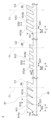
- FIG. 3 is a partial cross-sectional view of the light guide member 4 of the image display device 1. More specifically, FIG. 3 is a cross-sectional view of a portion of the light guide member 4 including the first diffraction structure region 61 in a plane including the periodic direction of the first diffraction structure region 61 and the thickness direction of the main body portion 40. be.
- the first diffraction structure region 61 is an uneven portion in the thickness direction of the main body portion 40 arranged so as to have periodicity in the periodic direction, that is, an uneven portion 611a of the first diffraction structure 611, It is constituted by an uneven portion 612a of the second diffraction structure 612 and an uneven portion 613a of the third diffraction structure 613.
- the uneven portions 611a, 612a, and 613a are convex portions that protrude from the main body portion 40.
- the periodic direction is a direction in which the uneven portions are arranged with periodicity.
- the periodic direction includes a component in the first propagation direction (in the case of the first diffraction structure region 61, the first direction D1).
- the periodic direction is set in a direction inclined with respect to the first direction D1.
- the periodic direction is the direction of the wave number vector of the first diffraction structure region 61.
- the periodic direction of the first diffraction structure region 61 is a direction inclined at 45 degrees with respect to the first direction D1 in a plane perpendicular to the thickness direction of the main body portion 40.
- the uneven portions 611a, 612a, and 613a extend along a direction inclined at 45 degrees with respect to the first direction D1 in a plane perpendicular to the thickness direction of the main body portion 40.
- the image light L1 propagating in the first direction D1 is converted into the image light L2 propagating in the second direction D2.
- the periodic direction is not limited to a direction inclined at 45 degrees with respect to the first direction D1 in a plane orthogonal to the thickness direction of the main body portion 40.
- the angle of the periodic direction with respect to the first direction D1 in a plane orthogonal to the thickness direction of the main body portion 40 may be 20 degrees to 70 degrees.
- the grating period is constant. That is, the first diffraction structure 611, the second diffraction structure 612, and the third diffraction structure 613 have the same grating period.
- the grating period is the distance between the same positions of two adjacent uneven portions in the periodic direction.
- the grating period of the first diffraction structure 611 is the distance between the same positions of two adjacent uneven portions 611a in the period direction.
- the grating period of the second diffraction structure 612 is the distance between the same positions of two adjacent uneven portions 612a in the period direction.
- the grating period of the third diffraction structure 613 is the distance between the same positions of two adjacent uneven portions 613a in the period direction.
- Examples of the distance between the same positions of adjacent uneven portions in the periodic direction include the distance between the front ends of adjacent uneven portions in the periodic direction, the distance between the centers of adjacent uneven portions in the periodic direction, and the distance between adjacent uneven portions in the periodic direction.
- An example of this is the distance between the rear ends of the uneven portions.
- the first diffraction structure 611, the second diffraction structure 612, and the third diffraction structure 613 have the same grating period, but because at least one of the grating height and the grating width is different, they have different diffraction efficiency characteristics.
- the grid height is the height of the uneven portions (the uneven portions 611a, 612a, 613a).
- the grid width is the width of the uneven portions (the uneven portions 611a, 612a, 613a).
- the width of the uneven portion is the width at the base end side (main body portion 40 side, lower end side in FIG. 3) of the uneven portion rather than the width at the tip side (upper end side in FIG. 3) of the uneven portion.
- the grating height of the first diffraction structure region 61 (the height of the uneven portion 611a) is Ha
- the grating height of the second diffraction structure 612 (the height of the uneven portion 612a) is Hb
- the grating height Ha and the grating height Hb satisfy the relationship Ha>Hb. That is, the grating height Ha of the first diffraction structure 611 is higher than the grating height Hb of the second diffraction structure 612.
- the grating width Wa and the grating width Wb are Wa> The relationship Wb is satisfied. That is, the grating width Wa of the first diffraction structure 611 is wider than the grating width Wb of the second diffraction structure 612.
- the first diffraction structure region 61 satisfies the following formulas (1) and (2). Thereby, the utilization efficiency of the image light L1 from the display element 2 can be improved.
- the grating period T and the grating height Ha preferably satisfies the relationship 0.3 ⁇ Ha/T ⁇ 1.2.
- Wa is the grating width of the first diffraction structure 611 (the width of the uneven portion 611a)
- the grating period T and the grating width Wa satisfy the relationship 0.7 ⁇ Wa/T ⁇ 1.0.
- the grating height of the second diffraction structure 612 (the height of the uneven portion 612a) is Hb
- the grating height Ha and the grating height Hb satisfy the relationship 1.2 ⁇ Ha/Hb ⁇ 10.0.
- the first diffraction structure region 61 satisfies the following formulas (3) to (5).
- the first diffraction structure 611 of the first diffraction structure region 61 can have the diffraction efficiency characteristics shown in FIG. 4.
- the first diffraction structure region 61 preferably satisfies the above equations (3) to (5) in addition to the above equations (1) and (2).
- FIG. 4 is a graph of the diffraction efficiency characteristics of the first diffraction structure 611 of the first diffraction structure region 61 of the replication region 6.
- the horizontal axis is the propagation angle [°]
- the vertical axis is the diffraction efficiency.
- the propagation angle is the incident angle of the image light L1 propagating in the first direction D1 with respect to the interface (the first surface 40a or the second surface 40b) of the main body portion 40.
- the first diffraction structure 611 has a diffraction efficiency characteristic in which the diffraction efficiency increases as the propagation angle increases.
- the first diffraction structure 611 has a diffraction efficiency characteristic in which the smaller the propagation angle, the smaller the diffraction efficiency.
- ⁇ amax is the maximum value of the propagation angle
- ⁇ amin is the minimum value of the propagation angle.
- Ea1 is the diffraction efficiency when the propagation angle is ⁇ amax
- Ea2 is the diffraction efficiency when the propagation angle is ⁇ amin. That is, Ea1 is the diffraction efficiency for the light that has the maximum angle of incidence (propagation angle) with respect to the interface of the main body 40 among the light propagating in the first direction D1, and the interface of the main body 40 among the light propagating in the first direction D1.
- the first diffraction structure 611 has a diffraction efficiency characteristic that satisfies the relationship Ea1>Ea2, where Ea2 is the diffraction efficiency for light whose incident angle (propagation angle) is the minimum.
- the second diffraction structure 612 of the first diffraction structure region 61 can have the diffraction efficiency characteristics shown in FIG. 5.
- the first diffraction structure region 61 preferably satisfies the above equations (3) to (5) in addition to the above equations (1) and (2).
- FIG. 5 is a graph of the diffraction efficiency characteristics of the second diffraction structure 612 of the first diffraction structure region 61 of the replication region 6.
- the horizontal axis is the propagation angle [°]
- the vertical axis is the diffraction efficiency. From FIG.
- the second diffraction structure 612 has a diffraction efficiency characteristic in which the diffraction efficiency changes in an upwardly convex parabolic shape with respect to the propagation angle.
- ⁇ bmax is the maximum value of the propagation angle
- ⁇ bmin is the minimum value of the propagation angle
- Eb1 is the diffraction efficiency when the propagation angle is ⁇ bmax
- Eb2 is the diffraction efficiency when the propagation angle is ⁇ bmin. That is, Eb1 is the diffraction efficiency for the light that has the maximum angle of incidence (propagation angle) with respect to the interface of the main body 40 among the light propagating in the first direction D1, and the interface of the main body 40 among the light propagating in the first direction D1.
- the second diffraction structure 612 has a diffraction efficiency characteristic that satisfies the relationship Eb1 ⁇ Eb2, where Eb2 is the diffraction efficiency for light whose incident angle (propagation angle) is the minimum.
- Eb1 the diffraction efficiency for light whose incident angle (propagation angle) is the minimum.
- the grating height of the third diffraction structure 613 is Hc
- the grating heights Ha, Hb, and Hc satisfy the relationships Ha ⁇ Hc and Hb ⁇ Hc.
- the grating width of the third diffraction structure 613 is Wc
- the grating widths Wa, Wb, and Wc satisfy the relationships Wc ⁇ Wa and Wc ⁇ Wb.
- the first diffraction structure region 61 satisfies the following formulas (6) to (9).
- the third diffraction structure 613 of the first diffraction structure region 61 can have the diffraction efficiency characteristics shown in FIG.
- FIG. 6 is a graph of the diffraction efficiency characteristics of the third diffraction structure 613 of the first diffraction structure region 61 of the replication region 6.
- the horizontal axis is the propagation angle [°]
- the vertical axis is the diffraction efficiency.
- the third diffraction structure 613 has a diffraction efficiency characteristic in which the diffraction efficiency decreases as the propagation angle increases.
- the third diffraction structure 613 has a diffraction efficiency characteristic in which the smaller the propagation angle, the higher the diffraction efficiency.
- ⁇ cmax is the maximum value of the propagation angle
- ⁇ cmin is the minimum value of the propagation angle.
- Ec1 is the diffraction efficiency when the propagation angle is ⁇ cmax
- Ec2 is the diffraction efficiency when the propagation angle is ⁇ cmin.
- Ec1 is the diffraction efficiency for the light that has the maximum angle of incidence (propagation angle) with respect to the interface of the main body 40 among the light propagating in the first direction D1, and the interface of the main body 40 among the light propagating in the first direction D1.
- the third diffraction structure 613 has a diffraction efficiency characteristic that satisfies the relationship Ec1 ⁇ Ec2, where Ec2 is the diffraction efficiency for light whose incident angle (propagation angle) is the minimum.
- the central axis C1 of the uneven portion 611a in the first diffraction structure 611 is inclined with respect to the thickness direction T1 of the main body portion 40.
- the central axis C1 passes through the center of the uneven portion 611a in a plane including the periodic direction of the first diffraction structure region 61 and the thickness direction T1 of the main body portion 40, assuming that the width Wa of the uneven portion 611a is constant. It is the axis.
- the inclination angle of the central axis C1 of the uneven portion 611a with respect to the thickness direction T1 of the main body portion 40 is the surface of the uneven portion 611a on the coupling region 5 side (the left surface in FIG. 3) with respect to the thickness direction T1 of the main body portion 40. ) is equal to the inclination angle.
- the central axis C1 of the concavo-convex portion 611a is inclined with respect to the thickness direction T1 of the main body portion 40, so that light is diffracted within a predetermined plane orthogonal to the thickness direction T1 of the main body portion 40.
- Efficiency can be controlled. For example, by adjusting the direction and angle in which the central axis C1 of the uneven portion 611a is inclined with respect to the thickness direction T1 of the main body portion 40, the amount of light propagating in a direction where light diffraction is unnecessary can be reduced and the light diffraction This makes it possible to increase the amount of light that propagates in the required direction. This makes it possible to efficiently guide the image light L1 from the display element 2 to the viewing area 8. Therefore, the utilization efficiency of the image light L1 from the display element 2 can be improved.
- the central axis C2 of the uneven portion 612a in the second diffraction structure 612 is inclined with respect to the thickness direction T1 of the main body portion 40.
- the central axis C2 is an axis passing through the center of the uneven portion 612a in a plane including the periodic direction of the first diffraction structure region 61 and the thickness direction of the main body portion 40, assuming that the width Wb of the uneven portion 612a is constant. It is.
- the inclination angle of the central axis C2 of the uneven portion 612a with respect to the thickness direction T1 of the main body 40 is the surface of the uneven portion 612a on the coupling region 5 side (the left surface in FIG. 3) with respect to the thickness direction T1 of the main body 40. ) is equal to the inclination angle.
- the central axis C2 of the concavo-convex portion 612a is inclined with respect to the thickness direction T1 of the main body 40, so that light is diffracted within a predetermined plane orthogonal to the thickness direction T1 of the main body 40.
- Efficiency can be controlled. For example, by adjusting the direction and angle in which the central axis C2 of the uneven portion 612a is inclined with respect to the thickness direction T1 of the main body portion 40, the amount of light propagating in a direction where light diffraction is not necessary is reduced, and the light diffraction is This makes it possible to increase the amount of light that propagates in the required direction. This makes it possible to efficiently guide the image light L1 from the display element 2 to the viewing area 8. Therefore, the utilization efficiency of the image light L1 from the display element 2 can be improved.
- the inclination angle of the central axis C1 of the uneven portion 611a in the first diffraction structure 611 with respect to the thickness direction T1 of the main body portion 40 and The inclination angle of the central axis C2 of the uneven portion 612a in the second diffraction structure 612 with respect to the thickness direction T1 of the main body portion 40 preferably satisfies the following relationship.
- the inclination angle of the central axis C1 of the uneven portion 611a in the first diffractive structure 611 with respect to the thickness direction T1 of the main body portion 40 is ⁇ a
- the central axis C2 of the uneven portion 612a in the second diffractive structure 612 is the thickness of the main body portion 40.
- the inclination angles ⁇ a and ⁇ b satisfy the relationship of 0.9 ⁇ a/ ⁇ b ⁇ 1.1.
- ⁇ a is set to be greater than 20 degrees and smaller than 65 degrees, for example.
- the central axis C3 of the uneven portion 613a in the third diffraction structure 613 is inclined with respect to the thickness direction T1 of the main body portion 40.
- the central axis C3 is an axis passing through the center of the uneven portion 613a in a plane including the periodic direction of the first diffraction structure region 61 and the thickness direction of the main body portion 40, assuming that the width Wc of the uneven portion 613a is constant. It is.
- the inclination angle of the central axis C3 of the uneven portion 613a with respect to the thickness direction T1 of the main body portion 40 is the surface of the uneven portion 613a on the coupling region 5 side (the left surface in FIG. 3) with respect to the thickness direction T1 of the main body portion 40. ) is equal to the inclination angle.
- the central axis C3 of the concavo-convex portion 613a is inclined with respect to the thickness direction T1 of the main body 40, light is diffracted within a predetermined plane orthogonal to the thickness direction T1 of the main body 40.
- Efficiency can be controlled. For example, by adjusting the direction and angle in which the central axis C3 of the uneven portion 613a is inclined with respect to the thickness direction T1 of the main body portion 40, the amount of light propagating in a direction where light diffraction is unnecessary can be reduced and the light diffraction This makes it possible to increase the amount of light that propagates in the required direction. This makes it possible to efficiently guide the image light L1 from the display element 2 to the viewing area 8. Therefore, the utilization efficiency of the image light L1 from the display element 2 can be improved.
- the inclination angle of the central axis C1 of the uneven portion 611a in the first diffraction structure 611 with respect to the thickness direction T1 of the main body portion 40 and The inclination angle of the central axis C2 of the uneven portion 612a in the third diffraction structure 613 with respect to the thickness direction T1 of the main body portion 40 preferably satisfies the following relationship.
- the inclination angle of the central axis C1 of the uneven portion 611a in the first diffractive structure 611 with respect to the thickness direction T1 of the main body portion 40 is ⁇ a
- the central axis C3 of the uneven portion 613a in the third diffractive structure 613 is the thickness of the main body portion 40.
- the uneven portion 611a in the first diffraction structure 611 has a periodicity of the first diffraction structure region 61 as it goes from the inside to the outside of the main body 40 in the thickness direction T1 of the main body 40. It has a shape in which the distance between the uneven portions 611a in the direction becomes large.
- the uneven portion 611a has a so-called wedge shape. In other words, the space 611b between the uneven portions 611a increases in size in the periodic direction of the first diffraction structure region 61 as it goes from the inside to the outside of the main body 40 in the thickness direction T1 of the main body 40.
- the distance G11 between the uneven parts 611a at the proximal end side (the lower end side in FIG. 3) of the uneven part 611a is greater than the distance G12 between the uneven parts 611a at the distal end side (the upper end side in FIG. 3) of the uneven part 611a. short.
- the uneven portion 612a in the second diffraction structure 612 has a period of the first diffraction structure region 61 as it goes from the inside to the outside of the main body 40 in the thickness direction T1 of the main body 40. It has a shape in which the distance between the concavo-convex portions 612a in the periodic direction is large.
- the uneven portion 612a has a so-called wedge shape. In other words, the space 612b between the uneven portions 612a increases in size in the periodic direction of the first diffraction structure region 61 as it goes from the inside to the outside of the main body 40 in the thickness direction T1 of the main body 40.
- the distance G21 between the uneven parts 612a at the proximal end side (the lower end side in FIG. 3) of the uneven part 612a is greater than the distance G22 between the uneven parts 612a at the distal end side (the upper end side in FIG. 3) of the uneven part 612a. short.
- the uneven portion 613a in the third diffraction structure 613 has a period of the first diffraction structure region 61 as it goes from the inside to the outside of the main body 40 in the thickness direction T1 of the main body 40. It has a shape in which the distance between the uneven portions 613a in the direction becomes large.
- the uneven portion 613a has a so-called wedge shape. In other words, the dimension of the space 613b between the uneven portions 613a in the periodic direction of the first diffraction structure region 61 increases from the inside to the outside of the main body 40 in the thickness direction T1 of the main body 40.
- the distance G31 between the uneven parts 613a at the proximal end side (the lower end side in FIG. 3) of the uneven part 613a is greater than the distance G32 between the uneven parts 613a at the distal end side (the upper end side in FIG. 3) of the uneven part 613a. short.
- the second diffraction structure region 62 is arranged in line with the first diffraction structure region 61 in the second direction D2.
- the second diffraction structure region 62 is a surface relief type diffraction grating, and irregularities are periodically formed.
- the second diffraction structure region 62 is a transmission type diffraction grating.
- the second diffraction structure region 62 converts the image light L2 propagating in a first propagation direction intersecting the thickness direction of the main body 40 into a plurality of image lights L3 propagating in a second propagation direction intersecting the first propagation direction.
- the device is configured to split in a first propagation direction.
- the second direction D2 is the first propagation direction
- the third direction D3 (the direction of the light L3 in FIG. 1) is the second propagation direction.
- the second diffraction structure region 62 directs a plurality of image lights L3 aligned in the second direction D2 toward the viewing region 8 by dividing the image light L2 propagating within the main body portion 40 of the light guide member 4. In this way, the second diffraction structure region 62 dilates the pupil of the image light L1 in the second direction D2. In other words, as shown in FIG.
- the second diffraction structure region 62 divides the image light L2 into a plurality of parallel image lights L3 directed toward the viewing field 8, thereby reducing the image light L1 projected by the projection optical system 7.
- the pupil is duplicated and dilated in the second direction D2.
- the second diffraction structure region 62 acts as an output structure that outputs the image light L1 that has entered the main body 40 through the coupling region 5 from the main body 40 toward the viewing field 8 .
- the size of the second diffraction structure region 62 is set so that all of the light L2 from the first diffraction structure region 61 enters the second diffraction structure region 62.
- the second diffraction structure region 62 has a rectangular shape.
- the second diffraction structure region 62 may include, for example, a plurality of concave portions or convex portions that extend in the first direction D1 and are lined up at predetermined intervals in the second direction D2.
- the projection optical system 7 projects image light L1 that forms an image output from the display element 2. Thereby, the projection optical system 7 allows the image light L1 from the display element 2 to enter the light guide member 4. As shown in FIG. 1, the projection optical system 7 is located between the display element 2 and the coupling region 5 of the light guide member 4. The projection optical system 7, for example, collimates the image light L1 from the display element 2 and makes it enter the coupling region 5. The projection optical system 7 makes the image light L1 enter the coupling region 5 as substantially collimated light.
- the projection optical system 7 is, for example, a biconvex lens.
- FIG. 7 is an explanatory diagram of an example of light propagation by the light guide member 4 of the image display device 1.
- the image light L1 from the display element 2 enters the coupling region 5 of the light guide member 4, and the coupling region 5 directs the image light L1 toward the replication region 6.
- the image light L1 includes a principal ray L11 corresponding to the center of the virtual image, and a plurality of subsidiary rays L12 and L13 that approach the principal ray L11 as they move from the projection optical system 7 toward the coupling area 5.
- the principal ray L11 is indicated by a solid arrow
- the subsidiary ray L12 is indicated by a dotted arrow
- the subsidiary ray L13 is indicated by a broken arrow. show.
- the sub-ray L12 corresponds to the light having the maximum angle of incidence (propagation angle) with respect to the interface of the main body 40 out of the image light L1.
- the sub-ray L13 corresponds to the light whose incident angle (propagation angle) with respect to the interface of the main body portion 40 is the minimum among the image light L1.
- the principal ray L11 and the subsidiary rays L12 and L13 of the image light L1 travel in the first direction D1 within the main body 40 of the light guide member 4 by being totally reflected by the first surface 40a and the second surface 40b,
- the first diffraction structure region 61 of the replication region 6 is reached.
- a first diffraction structure 611, a second diffraction structure 612, and a third diffraction structure 613 are arranged in this order in the first direction D1.
- the principal ray L11 and the sub rays L12 and L13 first reach the first diffraction structure 611.
- a portion of the principal ray L11 and the sub rays L12, L13 are directed toward the second diffraction structure region 62 by the first diffraction structure 611, and are extracted as output lights L11a, L12a, L13a through the second diffraction structure region 62. .
- the remainder of the principal ray L11 and sub-rays L12 and L13 that is not diffracted by the first diffraction structure 611 reaches the second diffraction structure 612.
- a portion of the principal ray L11 and the sub-rays L12 and L13 are directed toward the second diffraction structure region 62 by the second diffraction structure 612, and are extracted as output lights L11b, L12b, and L13b through the second diffraction structure region 62. .
- the remainder of the principal ray L11 and sub-rays L12 and L13 that is not diffracted by the second diffraction structure 612 reaches the third diffraction structure 613.
- Parts of the principal ray L11 and the sub rays L12 and L13 are directed toward the second diffraction structure region 62 by the third diffraction structure 613, and are extracted as output lights L11c, L12c, and L13c through the second diffraction structure region 62. .
- the light quantities of the emitted lights L11a to L11c, L12a to L12c, and L13a to L13c are schematically shown by the thickness of the corresponding arrow lines.
- the emitted light l3a does not reach the viewing area 8 and may be wasted.
- the first diffraction structure 611 has diffraction efficiency characteristics that satisfy the relationship Ea1>Ea2. Therefore, among the principal ray L11 and the sub rays L12 and L13, the sub ray L13 is less likely to be diffracted than the sub ray L12. That is, the sub-ray L13 is less likely to be directed toward the second diffraction structure region 62 than the sub-ray L12, and as a result, is less likely to be extracted from the main body 40 through the second diffraction structure region 62.
- the first diffraction structure 611 can reduce the amount of the emitted light Ll3a that does not reach the viewing area 8 in the first direction D1. Therefore, the utilization efficiency of the image light L1 from the display element 2 can be improved.
- the secondary ray L12 is more easily directed toward the second diffraction structure region 62 than the secondary ray L13, and as a result, is more easily extracted from the main body 40 through the second diffraction structure region 62. That is, the first diffraction structure 611 can increase the amount of emitted light Ll2a that reaches the viewing area 8 in the first direction D1. Therefore, the utilization efficiency of the image light L1 from the display element 2 can be improved. Moreover, this makes it possible to reduce the amount of the sub-ray L12 that passes through the first diffraction structure region 61 without being diffracted.
- the second diffraction structure 612 can compensate for the amount limited in the first diffraction structure 611, and thereby, The amount of the sub-ray L13 passing through the first diffraction structure region 61 without being diffracted can be reduced. Further, the amount of the sub-ray L12 passing through the first diffraction structure region 61 without being diffracted can be reduced.
- the third diffraction structure 613 has diffraction efficiency characteristics that satisfy the relationship Ec1 ⁇ Ec2. Therefore, among the principal ray L11 and the sub rays L12 and L13, the sub ray L13 is more easily diffracted than the sub ray L12. In other words, the secondary ray L13 is more easily directed toward the second diffraction structure region 62 than the secondary ray L12, and as a result, is more easily extracted from the main body 40 through the second diffraction structure region 62.
- the amount of sub-ray L13 taken out from the main body 40 is limited in the first diffraction structure 611, but the third diffraction structure 613 can also compensate for the amount limited in the first diffraction structure 611.
- the amount of light ray L13 passing through first diffraction structure region 61 can be reduced. As a result, the amount of emitted light L13c that reaches the viewing area 8 in the first direction D1 can be increased. Therefore, the utilization efficiency of the image light L1 from the display element 2 can be improved.
- the sub ray L12 is less likely to be diffracted than the sub ray L13, but before reaching the third diffraction structure 613, the sub ray L13 passes through the first diffraction structure 611 and the second diffraction structure 612. Since it is diffracted by , the influence is small.
- the optical system 3 described above includes a light guide member 4 that guides the image light L1 that forms an image output from the display element 2 to the user's visual field 8 as a virtual image.
- the light guiding member 4 includes a plate-shaped main body 40, a coupling region 5 formed on the main body 40, and allowing the image light L1 to enter the main body 40 so that the image light L1 propagates within the main body 40.
- Image light L1 formed on the main body 40 and propagating in a first propagation direction (first direction D1) intersecting the thickness direction T1 of the main body 40 is transferred to a second propagation direction (second direction D1) intersecting the first propagation direction.
- the D2) includes a replication region 6 having a first diffraction structure region 61 that is a surface relief type diffraction grating that divides the plurality of image lights L2 propagating in the first propagation direction.
- the first diffraction structure region 61 includes a first diffraction structure 611 and a second diffraction structure 612 located on the opposite side of the coupling region 5 with respect to the first diffraction structure 611 in the first propagation direction.
- the grating height of the first diffraction structure 611 is higher than the grating height of the second diffraction structure 612.
- the grating width of the first diffraction structure 611 is wider than the grating width of the second diffraction structure 612. This configuration can improve the utilization efficiency of the image light L1 from the display element 2.
- the diffraction structure region 61 has the following relationships: 0.3 ⁇ Ha/T ⁇ 1.2, 0.7 ⁇ Wa/T ⁇ 1.0, 1.2 ⁇ Ha/Hb ⁇ 10.0. Fulfill.
- T is the grating period of the first diffraction structure region 61.
- Ha is the grating height of the first diffraction structure 611.
- Wa is the grating width of the first diffraction structure 611.
- Hb is the grating height of the second diffraction structure 612. This configuration can improve the utilization efficiency of the image light L1 from the display element 2.
- the first diffraction structure 611 has a diffraction efficiency for the light (secondary ray L12) having the maximum angle of incidence with respect to the interface of the main body 40 among the light (image light L1) propagating in the first propagation direction. It has a diffraction efficiency characteristic that is higher than the diffraction efficiency for the light (secondary light ray L13) whose incident angle with respect to the interface of the main body portion 40 is the minimum among the light (image light L1) propagating in the first propagation direction. This configuration makes it possible to further improve the utilization efficiency of the image light L1 from the display element 2.
- the second diffraction structure 612 has a diffraction efficiency for the light (secondary ray L12) having the maximum angle of incidence with respect to the interface of the main body 40 among the light (image light L1) propagating in the first propagation direction. It has a diffraction efficiency characteristic that is higher than or equal to the diffraction efficiency for the light (secondary light ray L13) whose incident angle with respect to the interface of the main body portion 40 is the minimum among the light (image light L1) propagating in the first propagation direction. This configuration makes it possible to further improve the utilization efficiency of the image light L1 from the display element 2.
- the first diffraction structure region 61 further includes a third diffraction structure 613.
- the third diffraction structure 613 is on the opposite side of the first diffraction structure 611 with respect to the second diffraction structure 612 in the first propagation direction.
- the first diffraction structure region 61 satisfies both the relationships Ha ⁇ Hc and Hb ⁇ Hc.
- Ha is the grating height of the first diffraction structure 611.
- Hb is the grating height of the second diffraction structure 612.
- Hc is the grating height of the third diffraction structure 613.
- the first diffraction structure region 61 satisfies both the relationship Wc ⁇ Wa and the relationship Wc ⁇ Wb.
- Wc is the grating width of the third diffraction structure 613. This configuration makes it possible to further improve the utilization efficiency of the image light L1 from the display element 2.
- the third diffraction structure 613 has a diffraction efficiency for the light (secondary ray L12) having the maximum angle of incidence with respect to the interface of the main body 40 among the light (image light L1) propagating in the first propagation direction. It has a diffraction efficiency characteristic that is smaller than the diffraction efficiency for the light (secondary light ray L13) whose incident angle with respect to the interface of the main body portion 40 is the minimum among the light (image light L1) propagating in the first propagation direction. This configuration makes it possible to further improve the utilization efficiency of the image light L1 from the display element 2.
- the first diffraction structure region 61 is constituted by concavo-convex portions 611a, 612a, and 613a in the thickness direction T1 of the main body portion 40 arranged so as to have periodicity in a periodic direction including a component in the first propagation direction. be done.
- the central axis C1 of the uneven portion 611a in the first diffraction structure 611 is inclined with respect to the thickness direction T1 of the main body portion 40. This configuration makes it possible to further improve the utilization efficiency of the image light L1 from the display element 2.
- the uneven portions 611a in the first diffraction structure 611 have a shape in which the distance between the uneven portions 611a in the periodic direction increases from the inside to the outside of the main body 40 in the thickness direction T1 of the main body 40. This configuration enables easy manufacture of the light guide member 4.
- the central axis C2 of the uneven portion 612a in the second diffraction structure 612 is inclined with respect to the thickness direction T1 of the main body portion 40. This configuration makes it possible to further improve the utilization efficiency of the image light L1 from the display element 2.
- the inclination angle of the central axis C1 of the uneven portion 611a in the first diffraction structure 611 with respect to the thickness direction T1 of the main body portion 40 is ⁇ a
- the central axis C2 of the uneven portion 612a in the second diffraction structure 612 is 40 with respect to the thickness direction T1 is ⁇ b
- the relationship 0.9 ⁇ a/ ⁇ b ⁇ 1.1 is satisfied.
- the central axis C3 of the uneven portion 613a in the third diffraction structure 613 is inclined with respect to the thickness direction T1 of the main body portion 40. This configuration makes it possible to further improve the utilization efficiency of the image light L1 from the display element 2.
- the inclination angle of the central axis C1 of the uneven portion 611a in the first diffractive structure 611 with respect to the thickness direction T1 of the main body portion 40 is ⁇ a
- the central axis C3 of the uneven portion 613a in the third diffractive structure 613 is 40 with respect to the thickness direction T1 is ⁇ c
- the relationship 0.9 ⁇ a/ ⁇ c ⁇ 1.1 is satisfied.
- the replication region 6 has an emission structure (second diffraction structure region 62) that causes the image light L1 that has entered the main body 40 through the coupling region 5 to be emitted from the main body 40 toward the viewing region 8.
- emission structure second diffraction structure region 62
- the first diffraction structure region 61 has a first end 61a on the coupling region 5 side in the first propagation direction, and a second end 61b on the opposite side to the coupling region 5 in the first propagation direction.
- the first diffraction structure 611 is located within a region R11 that occupies at least 1/4 of the first diffraction structure region 61 from the first end 61a of the first diffraction structure region 61 in the first propagation direction. This configuration makes it possible to further improve the utilization efficiency of the image light L1 from the display element 2.
- the second diffraction structure 612 is located within a region R12 that occupies at least 1/2 of the first diffraction structure region 61 from the first end 61a of the first diffraction structure region 61 in the first propagation direction. This configuration makes it possible to further improve the utilization efficiency of the image light L1 from the display element 2.
- the third diffraction structure 613 is located at least on the side opposite to the first diffraction structure 611 with respect to the second diffraction structure 612 in the first propagation direction, and on the side opposite to the first diffraction structure 611 in the first propagation direction. It is located within a region R13 that occupies 1/4 of the first diffraction structure region 61 from the second end 61b. This configuration can further improve the utilization efficiency of the image light L1 from the display element 2.
- the optical system 3 further includes a projection optical system 7 that makes the image light L1 enter the coupling region 5 of the light guide member 4 as substantially collimated light. This configuration can further improve the utilization efficiency of the image light L1 from the display element 2.
- the image display device 1 described above includes an optical system 3 and a display element 2. This configuration can improve the utilization efficiency of the image light L1 from the display element 2.
- Embodiments of the present disclosure are not limited to the above embodiments.
- the embodiments described above can be modified in various ways depending on the design, etc., as long as the objects of the present disclosure can be achieved. Modifications of the above embodiment are listed below.
- the modified examples described below can be applied in combination as appropriate.
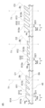
- FIG. 8 is a partial cross-sectional view of the light guide member 4A in Modification 1. More specifically, FIG. 8 is a cross-sectional view of a portion of the light guide member 4A that includes the first diffraction structure region 61A of the replication region 6A.
- the first diffraction structure region 61A in FIG. 8 includes a first diffraction structure 611, a second diffraction structure 612, and a third diffraction structure 613, similar to the first diffraction structure region 61 in FIG.
- the first diffraction structure region 61A in FIG. It differs from the first diffraction structure region 61 in FIG. 3 in shape and size.
- T 320 nm
- Ha 100 nm
- Wa 250 nm
- Hb 60 nm
- Wb 160 nm
- Hc 200 nm
- Wc 160 nm.
- the first diffraction structure 611 can have a diffraction efficiency characteristic that satisfies the relationship Ea1>Ea2.
- the second diffraction structure 612 may have diffraction efficiency characteristics that satisfy the relationship Eb1 ⁇ Eb2.
- the third diffraction structure 613 may have diffraction efficiency characteristics that satisfy the relationship Ec1 ⁇ Ec2. Therefore, the light guide member 4A of FIG. 8 can improve the utilization efficiency of the image light L1 from the display element 2.
- FIG. 9 is a partial cross-sectional view of the light guide member 4B in Modification 2.
- FIG. More specifically, FIG. 9 is a cross-sectional view of a portion of the light guide member 4B that includes the first diffraction structure region 61B of the replication region 6B.
- the first diffraction structure region 61B in FIG. 9 includes a first diffraction structure 611, a second diffraction structure 612, and a third diffraction structure 613, similar to the first diffraction structure region 61 in FIG.
- the first diffraction structure region 61B in FIG. It differs from the first diffraction structure region 61 in FIG. 3 and the first diffraction structure region 61A in FIG. 8 in shape and size.
- Ha>Hb, and formula (1) is satisfied.
- Wa>Wb, and formula (2) is satisfied.
- Ha/T 0.56, satisfying formula (3).
- Wa/T 0.88, which satisfies equation (4).
- Ha/Hb 2.25, satisfying formula (5).
- the grating heights Ha and Hc do not satisfy formula (6), but the grating heights Hb and Hc satisfy formula (7).
- the grating widths Wa and Wc satisfy equation (8), but the grating widths Wb and Wc do not satisfy equation (9).
- the first diffraction structure region 61B in FIG. 9 satisfies the above formulas (1) to (5), the first diffraction structure 611 can have diffraction efficiency characteristics that satisfy the relationship Ea1>Ea2.
- the second diffraction structure 612 may have diffraction efficiency characteristics that satisfy the relationship Eb1 ⁇ Eb2. Therefore, the light guide member 4B of FIG. 9 can improve the utilization efficiency of the image light L1 from the display element 2.
- the grating heights Ha, Hb, and Hc do not satisfy the relationship Ha ⁇ Hc, but satisfy the relationship Hb ⁇ Hc.
- the grating heights Ha, Hb, and Hc may satisfy at least one of the relationships Ha ⁇ Hc and Hb ⁇ Hc, but satisfy both the relationships Ha ⁇ Hc and Hb ⁇ Hc. It is better to satisfy This configuration makes it possible to further improve the utilization efficiency of the image light L1 from the display element 2.
- the grating widths Wa, Wb, and Wc satisfy the relationship Wc ⁇ Wa, but do not satisfy the relationship Wc ⁇ Wb.
- the grating widths Wa, Wb, and Wc may satisfy at least one of the relationships Wc ⁇ Wa and Wc ⁇ Wb, but satisfy both the relationships Wc ⁇ Wa and Wc ⁇ Wb. It's better. This configuration makes it possible to further improve the utilization efficiency of the image light L1 from the display element 2.
- FIG. 10 is a partial cross-sectional view of a light guide member 4C in modification example 3. More specifically, FIG. 9 is a cross-sectional view of a portion of the light guide member 4C that includes the first diffraction structure region 61C of the replication region 6C.
- the first diffraction structure region 61C in FIG. 10 includes a first diffraction structure 611, a second diffraction structure 612, and a third diffraction structure 613, similar to the first diffraction structure region 61 in FIG.
- the uneven portions 611a in the first diffraction structure 611 increase as the distance between the uneven portions 611a in the periodic direction goes from the inside to the outside of the main body 40 in the thickness direction T1 of the main body 40.
- the shape does not increase, and the distance between the concavo-convex portions 611a in the periodic direction is constant.
- the distance G11 between the uneven parts 611a on the proximal end side (the lower end side in FIG. 10) of the uneven part 611a is the same as the distance G12 between the uneven parts 611a on the distal end side (the upper end side in FIG. 10) of the uneven part 611a. equal.
- the uneven portions 612a in the second diffraction structure 612 increase as the distance between the uneven portions 612a in the periodic direction goes from the inside to the outside of the main body 40 in the thickness direction T1 of the main body 40.
- the shape does not increase, and the distance between the concavo-convex portions 612a in the periodic direction is constant.
- the distance G21 between the uneven parts 612a on the proximal end side (the lower end side in FIG. 10) of the uneven part 612a is the same as the distance G22 between the uneven parts 612a on the distal end side (the upper end side in FIG. 10) of the uneven part 612a. equal.
- the uneven portions 613a in the third diffraction structure 613 increase as the distance between the uneven portions 613a in the periodic direction goes from the inside to the outside of the main body 40 in the thickness direction T1 of the main body 40.
- the shape does not increase, and the distance between the concave and convex portions 613a in the periodic direction is constant.
- the distance G31 between the uneven parts 613a on the proximal end side (the lower end side in FIG. 10) of the uneven part 613a is the same as the distance G32 between the uneven parts 613a on the distal end side (the upper end side in FIG. 10) of the uneven part 613a. equal.
- the first diffraction structure 611 can have a diffraction efficiency characteristic that satisfies the relationship Ea1>Ea2.
- the second diffraction structure 612 may have diffraction efficiency characteristics that satisfy the relationship Eb1 ⁇ Eb2.
- the third diffraction structure 613 may have diffraction efficiency characteristics that satisfy the relationship Ec1 ⁇ Ec2. Therefore, the light guide member 4C in FIG. 10 can improve the utilization efficiency of the image light L1 from the display element 2.
- the uneven portions 611a in the first diffraction structure 611 do not necessarily have a shape in which the distance between the uneven portions 611a in the periodic direction increases from the inside to the outside of the main body 40 in the thickness direction T1 of the main body 40. It is not necessary to have it.
- the uneven portions 612a in the second diffraction structure 612 do not necessarily have a shape in which the distance between the uneven portions 612a in the periodic direction increases from the inside to the outside of the main body 40 in the thickness direction T1 of the main body 40. It is not necessary to have it.
- the uneven portions 613a in the third diffraction structure 613 do not necessarily have a shape in which the distance between the uneven portions 613a in the periodic direction increases from the inside to the outside of the main body 40 in the thickness direction T1 of the main body 40. It is not necessary to have it.
- FIG. 11 is a partial cross-sectional view of a light guide member 4D in modification example 4. More specifically, FIG. 11 is a cross-sectional view of a portion of the light guide member 4D that includes the first diffraction structure region 61D of the replication region 6D.
- the first diffraction structure region 61D in FIG. 11 includes a first diffraction structure 611, a second diffraction structure 612, and a third diffraction structure 613, similar to the first diffraction structure region 61 in FIG.
- the central axis C1 of the uneven portion 611a in the first diffraction structure 611 is parallel to the thickness direction T1 of the main body portion 40 without being inclined.
- the central axis C2 of the uneven portion 612a in the second diffraction structure 612 is parallel to the thickness direction T1 of the main body portion 40 without being inclined.
- the central axis C3 of the uneven portion 613a in the third diffraction structure 613 is parallel to the thickness direction T1 of the main body portion 40 without being inclined.
- the first diffraction structure 611 can have a diffraction efficiency characteristic that satisfies the relationship Ea1>Ea2.
- the second diffraction structure 612 may have diffraction efficiency characteristics that satisfy the relationship Eb1 ⁇ Eb2.
- the third diffraction structure 613 may have diffraction efficiency characteristics that satisfy the relationship Ec1 ⁇ Ec2. Therefore, the light guide member 4D of FIG. 11 can improve the utilization efficiency of the image light L1 from the display element 2.
- the central axis C1 of the uneven portion 611a in the first diffraction structure 611 does not necessarily have to be inclined with respect to the thickness direction T1 of the main body portion 40.
- the central axis C2 of the concavo-convex portion 612a in the second diffraction structure 612 does not necessarily have to be inclined with respect to the thickness direction T1 of the main body portion 40.
- the central axis C3 of the uneven portion 613a in the third diffraction structure 613 does not necessarily have to be inclined with respect to the thickness direction T1 of the main body portion 40.
- FIG. 12 is a plan view of a light guide member 4E in modification 5. As shown in FIG. 12, the coupling region 5 and the replication region 6E are formed on the first surface 40a of the main body portion 40 of the light guide member 4. As shown in FIG. 12, the coupling region 5 and the replication region 6E are formed on the first surface 40a of the main body portion 40 of the light guide member 4. As shown in FIG. 12, the coupling region 5 and the replication region 6E are formed on the first surface 40a of the main body portion 40 of the light guide member 4. As shown in FIG.
- the replication region 6E in FIG. 12 includes a first diffraction structure region 61E and a second diffraction structure region 62E.
- the first diffraction structure region 61E is arranged in line with the coupling region 5 in the first direction D1.
- the first diffraction structure region 61E is a surface relief type diffraction grating in which irregularities are periodically formed.
- the first diffraction structure region 61E is a reflection type diffraction grating.
- the first diffraction structure region 61E transforms the image light L1 propagating in a first propagation direction intersecting the thickness direction of the main body 40 into a plurality of image lights L2 propagating in a second propagation direction intersecting the first propagation direction.
- the device is configured to split in a first propagation direction.
- the first direction D1 is the first propagation direction
- the second direction D2 is the second propagation direction.
- the first diffraction structure region 61E divides the image light L1 propagating within the main body portion 40 of the light guide member 4, thereby directing a plurality of image lights L2 lined up in the first direction D1 toward the second diffraction structure region 62E. In this way, the first diffraction structure region 61E expands the pupil of the image light in the first direction D1.
- the first diffraction structure region 61E is constituted by concave and convex portions in the thickness direction of the main body portion 40 arranged so as to have periodicity in the period direction. 61, it does not have diffraction structures that differ depending on the location, such as the first to third diffraction structures 611 to 613.
- the second diffraction structure region 62E in FIG. 12 is arranged in line with the first diffraction structure region 61E in the second direction D2.
- the second diffraction structure region 62E is a surface relief type diffraction grating in which irregularities are periodically formed.
- the second diffraction structure region 62E is a transmission type diffraction grating.
- the second diffraction structure region 62E transforms the image light L2 propagating in the first propagation direction intersecting the thickness direction of the main body 40 into a plurality of image lights L3 propagating in the second propagation direction intersecting the first propagation direction.
- the device is configured to split in a first propagation direction.
- the second direction D2 is the first propagation direction
- the third direction D3 is the second propagation direction.
- the second diffraction structure region 62E directs a plurality of image lights L3 lined up in the second direction D2 toward the viewing area 8 by dividing the image light L2 propagating within the main body portion 40 of the light guide member 4E. In this way, the second diffraction structure region 62E expands the pupil of the image light in the second direction D2.
- the second diffraction structure region 62E in FIG. 12 includes a first diffraction structure 621, a second diffraction structure 622, and a third diffraction structure 623.
- the second diffraction structure 622 is located on the opposite side of the coupling region 5 with respect to the first diffraction structure 621 in the first propagation direction (second direction D2).
- the third diffraction structure 623 is located on the opposite side of the first diffraction structure 621 with respect to the second diffraction structure 622 in the first propagation direction (second direction D2).
- the first diffraction structure 621, the second diffraction structure 622, and the third diffraction structure 623 are arranged in this order in the first propagation direction (second direction D2).
- the second diffraction structure region 62E has a first end 62a on the coupling region 5 side in the first propagation direction (second direction D2) and a coupling region in the first propagation direction (second direction D2). 5 and a second end 62b on the opposite side.
- the first diffraction structure 621 is located within a region R21 that occupies at least 1/4 of the second diffraction structure region 62E from the first end 62a of the second diffraction structure region 62E in the first propagation direction.
- the second diffraction structure 622 is located within a region R22 that occupies at least 1/2 of the second diffraction structure region 62E from the first end 62a of the second diffraction structure region 62E in the first propagation direction.
- the third diffraction structure 623 is at least located on the opposite side of the first diffraction structure 621 with respect to the second diffraction structure 622 in the first propagation direction and extends from the second end 62b of the second diffraction structure region 62E in the first propagation direction. It is located within a region R23 that occupies 1/4 of the diffraction structure region 62E.
- region R21 is occupied by the first diffraction structure 621
- region R23 is occupied by the third diffraction structure 623
- region R21 and region R23 is the second diffraction structure 622. May be occupied.
- the second diffraction structure region 62E includes uneven portions in the thickness direction of the main body portion 40 arranged so as to have periodicity in the periodic direction, that is, the uneven portions of the first diffraction structure 621, the uneven portions of the second diffraction structure 622, and It is constituted by the concavo-convex portion of the third diffraction structure 623.
- the uneven portion is a convex portion that protrudes from the main body portion 40.
- the periodic direction is a direction in which the uneven portions are arranged with periodicity.
- the periodic direction includes a component in the first propagation direction (second direction D2 in the case of the second diffraction structure region 62E).
- the periodic direction is set in the second direction D2.
- the periodic direction includes only a component in the second direction D2.
- the periodic direction is the direction of the wave number vector of the second diffraction structure region 62.
- the uneven portions extend in the first direction D1 and are arranged at predetermined intervals in the second direction D2.
- the grating period is constant. That is, the first diffraction structure 621, the second diffraction structure 622, and the third diffraction structure 623 have the same grating period.
- the grating period is the distance between the same positions of two adjacent uneven portions in the periodic direction.
- the first diffraction structure 621, the second diffraction structure 622, and the third diffraction structure 623 in the second diffraction structure region 62E have the same grating period, but have different diffraction efficiencies because at least one of the grating height and the grating width is different. have characteristics.
- the grating height and grating width of the first diffraction structure 621, second diffraction structure 622, and third diffraction structure 623 of the second diffraction structure region 62E are the same as those of the first diffraction structure 621 of the first diffraction structure region 61 in the above embodiment. , may be set similarly to the grating height and grating width of the second diffraction structure 622 and the third diffraction structure 623.
- the grating period of the second diffraction structure region 62E is T
- the grating height (height of the uneven portion) of the first diffraction structure 621 is Ha
- the grating period T and the grating height Ha are 0.3 ⁇ Ha. /T ⁇ 1.2 is satisfied.
- the grating width (width of the uneven portion) of the first diffraction structure 621 is Wa
- the grating period T and the grating width Wa satisfy the relationship 0.7 ⁇ Wa/T ⁇ 1.0.
- the grating height (height of the uneven portion) of the second diffraction structure 622 is Hb
- the grating height Ha and the grating height Hb satisfy the relationship 1.2 ⁇ Ha/Hb ⁇ 10.0.
- the diffraction efficiency for the light having the maximum angle of incidence (propagation angle) with respect to the interface of the main body portion 40 is set to Ea1, and the light propagates in the second direction D2.
- the first diffraction structure 621 has a diffraction efficiency characteristic that satisfies the relationship Ea1>Ea2, where Ea2 is the diffraction efficiency for light whose incident angle (propagation angle) with respect to the interface of the main body portion 40 is the minimum.
- Eb1 is the diffraction efficiency for the light that has the maximum angle of incidence (propagation angle) with respect to the interface of the main body 40 among the light propagating in the second direction D2
- Eb1 is the diffraction efficiency for the light that propagates in the second direction D2.
- Eb2 is the diffraction efficiency for light having the minimum incident angle (propagation angle) with respect to the interface of the main body portion 40
- the grating height of the third diffraction structure 623 is Hc
- the grating heights Ha, Hb, and Hc satisfy the relationships Ha ⁇ Hc and Hb ⁇ Hc.
- the grating width of the third diffraction structure 623 is Wc
- the grating widths Wa, Wb, and Wc satisfy the relationships Wc ⁇ Wa and Wc ⁇ Wb.
- the third diffraction structure 623 has a diffraction efficiency characteristic that satisfies the relationship Ec1 ⁇ Ec2, where Ec2 is the diffraction efficiency for light whose incident angle (propagation angle) with respect to the interface of the main body portion 40 is the minimum.
- the first diffraction structure 621 has a diffraction efficiency characteristic that satisfies the relationship Ea1>Ea2. Therefore, the first diffraction structure 621 can reduce the amount of emitted light that does not reach the viewing area 8 in the second direction D2. Therefore, the utilization efficiency of the image light L1 from the display element 2 can be improved. On the other hand, the first diffraction structure 621 can increase the amount of emitted light that reaches the viewing area 8 in the second direction D2. Therefore, the utilization efficiency of the image light L1 from the display element 2 can be improved.
- the second diffraction structure 612 can reduce variations in the amount of emitted light L11b, L12b, and L13b in the second direction D2.
- the third diffraction structure 623 has diffraction efficiency characteristics that satisfy the relationship Ec1 ⁇ Ec2. As a result, the amount of emitted light that reaches the viewing area 8 in the second direction D2 can be increased. Therefore, the utilization efficiency of the image light L1 from the display element 2 can be improved. Therefore, the second diffraction structure region 62E can improve the utilization efficiency of the image light L1 from the display element 2.
- the light guide members 4 to 4E do not necessarily need to be arranged so that the light guide members 4 to 4E and the viewing area 8 are aligned in a straight line.
- the optical path from the light guide members 4 to 4E to the viewing area 8 is not necessarily a straight line.
- the light from the light guide members 4 to 4E may be reflected by a reflector, a combiner, a windshield, etc., and then made to enter the viewing area 8.
- the optical path from the light guide members 4 to 4E to the viewing area 8 is not linear but, for example, L-shaped.
- the shape and dimensions of the light guide members 4 to 4E are such that the user can see the virtual image even if the length of the optical path from the light guide members 4 to 4E to the viewing area 8 is 300 mm or more. is set.
- the dimension of the viewing area 8 corresponding to the first propagation direction (first direction D1) of the replication region 6 is V1
- the dimension of the replication region 6 in the first propagation direction (first direction D1) is E1
- This configuration can also be used for a head-up display (HUD), etc., in which the optical system 3 is relatively farther away from the user than the HMD.
- HUD head-up display
- the coupling region 5 is not limited to a surface relief type diffraction grating, but may include a volume hologram element (holographic diffraction grating) or a half mirror.
- the replication region 6 may be a surface relief type diffraction grating, either a transmission type or a reflection type.
- the surface relief type diffraction grating is not limited to the same material as the light guide members 4 to 4E, and may be formed of a different material.
- the material of the light guide members 4 to 4E may be glass, and the material of the surface relief type diffraction grating may be an ultraviolet curing resin.
- a surface relief type diffraction grating can be formed by nanoimprint technology.
- the coupling region 5 or the replication region 6 does not necessarily have to be formed integrally with the main body 40, and may be formed separately from the main body 40.
- the replication region 6 may include any one of the first diffraction structure regions 61 to 61D and a second diffraction structure region 62E.
- the replication area 6 can reduce the amount of emitted light that does not reach the viewing area 8 in both the first direction D1 and the second direction D2, and improve the utilization efficiency of the image light L1 from the display element 2.
- the replication regions 6 to 6E do not need to have both the first diffraction structure region 61 and the second diffraction structure region 62.
- the duplicate regions 6 to 6E expand the pupil of the image light L1 only in one direction.
- the first diffraction structure regions 61 to 61E may be configured such that the second propagation direction D2 is a direction from the main body 40 to the viewing region 8.
- the first diffraction structure regions 61 to 61E may define an output structure in which the image light L1 that has entered the main body 40 through the coupling region 5 is emitted from the main body 40 toward the viewing area 8.
- the uneven portions of the first diffraction structure regions 61 to 61E may be protrusions (protrusions), recesses, or a combination of protrusions and recesses, as long as they can constitute a diffraction grating.
- the central axis of the uneven portion may be, for example, the central axis of the protrusion or the central axis of the recess. This also applies to the second diffraction structure regions 62 and 62E.
- the projection optical system 7 may include a first optical element and a second optical element as a plurality of optical elements instead of a single optical element.
- the first optical element is, for example, a cemented lens that is a combination of a negative meniscus lens and a biconvex lens
- the second optical element is a cemented lens that is a combination of a positive meniscus lens and a negative meniscus lens. Note that the optical system 3 does not need to include the projection optical system 7.
- the projection optical system 7 and the coupling region 5 do not necessarily need to be aligned in a straight line. That is, the optical path of the image light L1 from the projection optical system 7 to the coupling region 5 is not necessarily a straight line.
- the image light L1 from the projection optical system 7 may be reflected by a reflector and made to enter the coupling region 5.
- the optical path of the image light L1 from the projection optical system 7 to the coupling region 5 is not linear but, for example, L-shaped.
- the image display device 1 may include a plurality of light guide members 4 to 4E each corresponding to the wavelength of light included in the image light L1. This allows a color image to be provided to the user.
- the first aspect is an optical system (3) in which a light guide member (4) guides image light (L1) forming an image output from a display element (2) to a user's visual field (8) as a virtual image. ;4A;4B;4C;4D;4E).
- the light guide member (4; 4A; 4B; 4C; 4D; 4E) is formed in a plate-shaped main body (40) and the main body (40), and the image light (L1) is directed to the main body (40).
- L2 includes a duplicate region (6; 6A; 6B; 6C; 6D; 6E) having a diffraction structure region (61) that is a surface relief type diffraction grating that divides in the first propagation direction (D1). .
- the diffraction structure region (61) is located on the opposite side of the first diffraction structure (611) and the coupling region (5) with respect to the first diffraction structure (611) in the first propagation direction (D1). a second diffraction structure (612).
- the grating height of the first diffractive structure (611) is higher than the grating height of the second diffractive structure (612).
- the grating width of the first diffraction structure (611) is wider than the grating width of the second diffraction structure (612). This aspect can improve the utilization efficiency of the image light (L1) from the display element (2).
- the second aspect is an optical system (3) based on the first aspect.
- the diffraction structure region (61) has 0.3 ⁇ Ha/T ⁇ 1.2, 0.7 ⁇ Wa/T ⁇ 1.0, 1.2 ⁇ Ha/Hb ⁇ 10.0 , satisfies the relationship.
- T is the grating period of the diffraction structure region (61)
- Ha is the grating height of the first diffraction structure (611)
- Wa is the grating width of the first diffraction structure (611).
- Hb is the grating height of the second diffraction structure (612). This aspect can improve the utilization efficiency of the image light (L1) from the display element (2).
- the third aspect is an optical system (3) based on the first or second aspect.
- the first diffraction structure (611) is configured to respond to light (L12) that has a maximum angle of incidence with respect to the interface of the main body (40) among the light that propagates in the first propagation direction (D1). It has a diffraction efficiency characteristic in which the diffraction efficiency is larger than the diffraction efficiency for light (L13) having the minimum incident angle with respect to the interface of the main body (40) among the light propagating in the first propagation direction (D1). This aspect makes it possible to further improve the utilization efficiency of the image light (L1) from the display element (2).
- the fourth aspect is an optical system (3) based on the third aspect.
- the second diffraction structure (612) is configured to respond to light (L12) that has a maximum angle of incidence with respect to the interface of the main body (40) among the light that propagates in the first propagation direction (D1). It has a diffraction efficiency characteristic in which the diffraction efficiency is greater than or equal to the diffraction efficiency for light (L13) having the smallest incident angle with respect to the interface of the main body (40) among the light propagating in the first propagation direction (D1).
- This aspect makes it possible to further improve the utilization efficiency of the image light (L1) from the display element (2).
- the fifth aspect is an optical system (3) based on any one of the first to fourth aspects.
- the diffraction structure region (61) further includes a third diffraction structure (613).
- the third diffraction structure (613) is on the opposite side of the first diffraction structure (611) with respect to the second diffraction structure (612) in the first propagation direction (D1).
- the diffraction structure region (61) satisfies at least one of the relationships Ha ⁇ Hc and Hb ⁇ Hc.
- Hc is the grating height of the third diffraction structure (613). This aspect makes it possible to further improve the utilization efficiency of the image light (L1) from the display element (2).
- the diffraction structure region (61) preferably satisfies both the relationship Ha ⁇ Hc and the relationship Hb ⁇ Hc. In this case, it is possible to further improve the utilization efficiency of the image light (L1) from the display element (2).
- the sixth aspect is an optical system (3) based on the fifth aspect.
- the diffraction structure region (61) satisfies at least one of the relationships Wc ⁇ Wa and Wc ⁇ Wb.
- Wa is the grating width of the first diffraction structure (611).
- Wb is the grating width of the second diffraction structure (612).
- Wc is the grating width of the third diffraction structure (613).
- the diffraction structure region (61) preferably satisfies both the relationship Wc ⁇ Wa and the relationship Wc ⁇ Wb. In this case, it is possible to further improve the utilization efficiency of the image light (L1) from the display element (2).
- the seventh aspect is an optical system (3) based on the fifth or sixth aspect.
- the third diffraction structure (613) is configured to respond to light (L12) that has a maximum angle of incidence with respect to the interface of the main body (40) among the light that propagates in the first propagation direction (D1). It has a diffraction efficiency characteristic in which the diffraction efficiency is smaller than the diffraction efficiency for light (L13) having the minimum incident angle with respect to the interface of the main body (40) among the light propagating in the first propagation direction (D1). This aspect makes it possible to further improve the utilization efficiency of the image light (L1) from the display element (2).
- the eighth aspect is an optical system (3) based on any one of the first to seventh aspects.
- the diffraction structure region (61) is arranged to have periodicity in a periodic direction including a component in the first propagation direction (D1) in the thickness direction (T1) of the main body (40). ) with uneven parts (611a, 612a, 613a).
- the central axis (C1) of the uneven portion (611a) in the first diffraction structure (611) is inclined with respect to the thickness direction (T1) of the main body (40).
- the ninth aspect is an optical system (3) based on the eighth aspect.
- the uneven portion (611a) in the first diffraction structure (611) increases from the inside to the outside of the main body (40) in the thickness direction (T1) of the main body (40). It has a shape in which the distance between the concave and convex portions (611a) in the periodic direction becomes large. This aspect allows for easy manufacture of the light guide member (4).
- the tenth aspect is an optical system (3) based on the eighth or ninth aspect.
- the central axis (C2) of the uneven portion (612a) in the second diffraction structure (612) is inclined with respect to the thickness direction (T1) of the main body (40). This aspect makes it possible to further improve the utilization efficiency of the image light (L1) from the display element (2).
- the eleventh aspect is an optical system (3) based on the tenth aspect.
- the inclination angle of the central axis (C1) of the uneven portion (611a) in the first diffraction structure (611) with respect to the thickness direction (T1) of the main body portion (40) is ⁇ a
- This aspect makes it possible to further improve the utilization efficiency of the image light (L1) from the display element (2).
- the twelfth aspect is an optical system (3) based on any one of the eighth to eleventh aspects.
- the diffraction structure region (61) further includes a third diffraction structure (613).
- the third diffraction structure (613) is on the opposite side of the first diffraction structure (611) with respect to the second diffraction structure (612) in the first propagation direction (D1).
- the diffraction structure region (61) satisfies at least one of the relationships Ha ⁇ Hc and Hb ⁇ Hc.
- Hc is the grating height of the third diffraction structure (613).
- the central axis (C3) of the uneven portion (613a) in the third diffraction structure (613) is inclined with respect to the thickness direction (T1) of the main body (40). This aspect makes it possible to further improve the utilization efficiency of the image light (L1) from the display element (2).
- the diffraction structure region (61) preferably satisfies at least one of the relationships Wc ⁇ Wa and Wc ⁇ Wb.
- Wa is the grating width of the first diffraction structure (611).
- Wb is the grating width of the second diffraction structure (612).
- Wc is the grating width of the third diffraction structure (613).
- the thirteenth aspect is an optical system (3) based on the twelfth aspect.
- the inclination angle of the central axis (C1) of the uneven portion (611a) in the first diffraction structure (611) with respect to the thickness direction (T1) of the main body portion (40) is ⁇ a
- This aspect makes it possible to further improve the utilization efficiency of the image light (L1) from the display element (2).
- a fourteenth aspect is an optical system (3) based on any one of the first to thirteenth aspects.
- the replication region (6; 6A; 6B; 6C; 6D; 6E) allows the image light (L1) that has entered the main body portion (40) to be transferred to the main body by the coupling region (5). It has an emission structure (62) for emitting light from the part (40) toward the viewing area (8).
- the light guide member (4) can be miniaturized.
- a fifteenth aspect is an optical system (3) based on any one of the first to fourteenth aspects.
- the dimension of the viewing area (8) corresponding to the first propagation direction (D1) of the replicating area (6; 6A; 6B; 6C; 6D; 6E) is V1
- the replicating area (6; ; 6A; 6B; 6C; 6D; 6E) in the first propagation direction (D1) is E1
- the relationship 1.0 ⁇ E1/V1 ⁇ 5.0 is satisfied.
- a sixteenth aspect is an optical system (3) based on any one of the first to fifteenth aspects.
- the diffraction structure region (61) has a first end (61a) on the coupling region (5) side in the first propagation direction (D1), and a first end (61a) on the coupling region (5) side in the first propagation direction (D1). and a second end (61b) opposite to the bonding region (5).
- the first diffraction structure (611) extends from the first end (61a) of the diffraction structure region (61, 62) to 1/4 of the diffraction structure region (61, 62) in the first propagation direction (D1). It is within the region (R11) that occupies . This aspect makes it possible to further improve the utilization efficiency of the image light (L1) from the display element (2).
- the seventeenth aspect is an optical system (3) based on the sixteenth aspect.
- the second diffraction structure (612) extends from the first end (61a) of the diffraction structure region (61) to one of the diffraction structure regions (61) in the first propagation direction (D1). It is within the region (R12) occupying /2. This aspect makes it possible to further improve the utilization efficiency of the image light (L1) from the display element (2).
- the 18th aspect is an optical system (3) based on the 16th or 17th aspect.
- the diffraction structure region (61) further includes a third diffraction structure (613).
- the third diffraction structure (613) is opposite to the first diffraction structure (611) with respect to the second diffraction structure (612) in the first propagation direction (D1), and is arranged in the first propagation direction (D1). ) is located within a region (R13) occupying 1/4 of the diffraction structure region (61) from the second end (61b) of the diffraction structure region (61).
- the diffraction structure region (61) satisfies at least one of the relationships Ha ⁇ Hc and Hb ⁇ Hc.
- Ha is the grating height of the first diffraction structure (611).
- Hb is the grating height of the second diffraction structure (612).
- Hc is the grating height of the third diffraction structure (613). This aspect can further improve the utilization efficiency of the image light (L1) from the display element (2).
- a nineteenth aspect is an optical system (3) based on any one of the first to eighteenth aspects.
- the optical system (3) converts the image light (L1) into substantially collimated light to the coupling region (5) of the light guide member (4; 4A; 4B; 4C; 4D; 4E). It further includes a projection optical system (7) for making the light enter. This aspect can further improve the utilization efficiency of the image light (L1) from the display element (2).
- a 20th aspect is an image display device (1) comprising an optical system (3) based on any one of the 1st to 19th aspects and the display element (2). This aspect can improve the utilization efficiency of the image light (L1) from the display element (2).
- the present disclosure is applicable to optical systems and image display devices. Specifically, the present disclosure is applicable to an optical system for guiding image light from a display element to a user's visual field as a virtual image, and an image display device including this optical system.
Abstract
表示素子からの画像光の利用効率を向上できる光学系、及び、画像表示装置を提供する。光学系は、画像光をユーザの視野領域に虚像として導く導光部材4を備える。導光部材4は、本体部の厚み方向に交差する第1伝搬方向に伝搬する画像光を、第1伝搬方向に交差する第2伝搬方向に伝搬する複数の画像光に、第1伝搬方向において分割する表面レリーフ型の回折格子である回折構造領域61を有する。回折構造領域61は、第1回折構造611と、第1伝搬方向において第1回折構造611に対して結合領域と反対側にある第2回折構造612とを含む。第1回折構造611の格子高さは、第2回折構造612の格子高さより高い。第1回折構造611の格子幅は、第2回折構造612の格子幅より広い。
Description
本開示は、光学系、及び、画像表示装置に関する。
特許文献1は、画像表示装置として、デジタル又は仮想イメージを視認者に提示するビューイングオプティクスアセンブリ(VOA)を開示する。VOAは、プロジェクタと、視認者が着用するアイピースとを備える。アイピースは、複数のアイピースレイヤを含む。各アイピースレイヤは、平面導波路、及び、結合格子、直交瞳拡張領域、及び、出射瞳拡張領域を含む。プロジェクタは、画像光を、アイピースの結合格子に照射する。結合格子は、プロジェクタからの画像光を平面導波路に結合して、直交瞳拡張領域に向けて伝搬させる。平面導波路は、全反射により、画像光を水平方向に伝搬する。直交瞳拡張領域は、結合格子からの画像光を複製し、出射瞳拡張領域に向ける回折要素を含む。出射瞳拡張領域は、平面導波路内を伝搬する画像光の一部を視認者の目に向けて出射させる回折要素を含む。
特許文献1は、位置により出射する光の量が減少することを低減するために、回折構造において、位置の関数として回折要素の高さ又は深さを変更することで、光の均一性を向上させることを開示する。
ところで、画像光には広がりがあるため、画像光が導波路内を全反射しながら伝搬する角度(伝搬角)にはばらつきがある。画像光のうち伝搬角が最大となる光と画像光のうち伝搬角が最小となる光とは、同じ回折格子に対しても異なる挙動を示し得るから、プロジェクタ等の表示素子からの画像光の利用効率の向上のためには、伝搬角のばらつきを考慮することが求められ得る。しかしながら、特許文献1では、このような伝搬角のばらつきについては考慮されていない。
本開示は、表示素子からの画像光の利用効率を向上できる光学系、及び、画像表示装置を提供する。
本開示の一態様にかかる光学系は、表示素子から出力される画像を形成する画像光をユーザの視野領域に虚像として導く導光部材を備える。導光部材は、板状の本体部と、本体部に形成され、画像光が本体部内を伝播するように画像光を本体部内に入射させる結合領域と、本体部に形成され、本体部の厚み方向に交差する第1伝搬方向に伝搬する画像光を、第1伝搬方向に交差する第2伝搬方向に伝搬する複数の画像光に、第1伝搬方向において分割する表面レリーフ型の回折格子である回折構造領域を有する複製領域と、を備える。回折構造領域は、第1回折構造と、第1伝搬方向において第1回折構造に対して結合領域とは反対側にある第2回折構造とを含む。前記第1回折構造の格子高さは、前記第2回折構造の格子高さより高い。前記第1回折構造の格子幅は、前記第2回折構造の格子幅より広い。
本開示の一態様にかかる画像表示装置は、上記の光学系と、表示素子とを備える。
本開示の態様は、表示素子からの画像光の利用効率を向上できる。
以下、適宜図面を参照しながら、実施の形態を詳細に説明する。但し、必要以上に詳細な説明は省略する場合がある。例えば、既によく知られた事項の詳細説明や実質的に同一の構成に対する重複説明を省略する場合がある。これは、以下の説明が不必要に冗長になるのを避け、当業者の理解を容易にするためである。なお、発明者(ら)は、当業者が本開示を十分に理解するために添付図面および以下の説明を提供するのであって、これらによって特許請求の範囲に記載の主題を限定することを意図するものではない。
上下左右等の位置関係は、特に断らない限り、図面に示す位置関係に基づくものとする。以下の実施の形態において説明する各図は、模式的な図であり、各図中の各構成要素の大きさ及び厚さそれぞれの比が、必ずしも実際の寸法比を反映しているとは限らない。また、各要素の寸法比率は図面に図示された比率に限られるものではない。
本開示において、光に関して「〇〇方向に向かわせる」及び「〇〇方向に伝播させる」等の表現は、画像を形成する光が全体として〇〇方向に向かうことを意味し、画像を形成する光に含まれる光線は〇〇方向に対して傾いていてもよい。例えば、「〇〇方向に向かう光」は、この光の主光線が〇〇方向に向いていればよく、光の副光線は〇〇方向に対して傾いていてもよい。
[1.実施の形態]
[1.1 構成]
図1は、画像表示装置1の構成例の概略図である。画像表示装置1は、例えば、ユーザの頭部に装着され、画像(映像)を表示するヘッドマウントディスプレイ(HMD)である。図1に示すように、画像表示装置1は、表示素子2と、光学系3とを備える。
[1.1 構成]
図1は、画像表示装置1の構成例の概略図である。画像表示装置1は、例えば、ユーザの頭部に装着され、画像(映像)を表示するヘッドマウントディスプレイ(HMD)である。図1に示すように、画像表示装置1は、表示素子2と、光学系3とを備える。
表示素子2は、画像(映像)を表示するために、画像を形成する画像光L1を出力する。ここで、図1は簡単のために、画像光L1を、指向性を持った光として描画しているが、実際は視野角に相当する角度を持つ光として光学系3に入射する。表示素子2の光軸は、画像光L1の光軸である。画像光L1の光軸は、例えば、表示素子2の中心から出力される光の光軸である。表示素子2の例としては、液晶ディスプレイ、有機ELディスプレイ、走査型MEMSミラー、LCOS(Liquid Crystal On Silicon)、DMD(Digital Mirror Device)、マイクロLED等の既知のディスプレイが挙げられる。
光学系3は、表示素子2が出力する画像光L1を、ユーザの目に対して設定される視野領域8に導く。視野領域8では、表示素子2が形成する画像をユーザが自身の目で途切れることなく視認できる。特に、本実施の形態において、光学系3は、瞳拡張の作用により、視野領域8を広げる。つまり、光学系3は、画像光L1の瞳を複製することによって、視野領域8を広げる。本実施の形態において、視野領域8は、矩形状の平面で規定される。
図1に示すように、光学系3は、導光部材4と、投射光学系7とを備える。
導光部材4は、表示素子2から出力される画像を形成する画像光L1をユーザの視野領域8に虚像として導く。
図1に示すように、導光部材4は、本体部40と、結合領域5と、複製領域6とを備える。
本体部40は、可視光領域において透明な材料で形成される。本体部40は、板状である。本実施の形態では、本体部40は、矩形の板状である。本体部40は、本体部40の厚み方向の第1面40a及び第2面40bを有する。図1に示すように、本体部40は、第1面40aを表示素子2側に、第2面40bを視野領域8側に向けて配置される。
図2は、表示素子2側から見た導光部材4の平面図ある。図2に示すように、結合領域5と、複製領域6とは、導光部材4の本体部40の第1面40aに形成される。
結合領域5は、画像光L1が本体部40内を伝播するように画像光L1を本体部40内に入射させる。本実施の形態において、結合領域5は、画像光L1が本体部40内を、本体部40の厚み方向に直交する第1方向D1(図2の左方向)に伝播するように画像光L1を本体部40内に入射させる。本実施の形態では、結合領域5は、表示素子2と導光部材4との結合(カップリング)に用いられる。結合領域5は、画像光L1が全反射条件で本体部40内を伝播するように画像光L1を本体部40内に入射させる。ここでいう「結合(カップリング)」とは、全反射条件で導光部材4の本体部40内を伝播する状態である。
結合領域5は、画像光L1に対する回折作用を有する回折構造体により構成される。結合領域5の回折構造体は、例えば、透過型の表面レリーフ型の回折格子であり、凹凸が周期的に形成されている。結合領域5の回折構造体は、例えば、本体部40の厚み方向に直交し第1方向D1に交差する第2方向D2(図2の下方向)に延びて第1方向D1に所定間隔で並ぶ複数の凹部又は凸部を含んでよい。本開示において、「回折構造」は、複数の凹部又は凸部が周期的に並ぶ「周期構造」であるともいえる。ただし、「回折構造」は、製造上の制約その他の状況によって、「周期構造」に加えて、完全ではない周期構造を含む場合がある。本実施の形態において、第2方向D2は、第1方向D1とも直交する。結合領域5は、回折作用によって、画像光L1を、本体部40内に、第1面40a及び第2面40bに対して全反射する条件で入射させる。結合領域5によって、画像光L1は、本体部40内を、第1面40a及び第2面40bで全反射されることで、第1方向D1に進む。
結合領域5の大きさは、投射光学系7を経た表示素子2からの画像光L1の一部又は全部が結合領域5に入射するように設定される。本実施の形態において、図2に示すように、結合領域5は、四角形状である。
複製領域6は、結合領域5から導光部材4の本体部40内に入射した画像光L1を分割することで、画像光L1の瞳を複製して拡張する。本実施の形態において、複製領域6は、結合領域5から導光部材4の本体部40内に入射した画像光L1を、第3方向D3に進む複数の画像光L3に分割して視野領域8に出射することで、画像光L1の瞳を複製して拡張する。第3方向D3は、導光部材4から視野領域8に向かう方向である。本実施の形態において、第3方向D3は、第1方向D1及び第2方向D2にそれぞれ直交する。本実施の形態では、複数の画像光L3は、互いに平行である。「複数の画像光L3は、互いに平行である」ことは、厳密な意味で複数の画像光L3が互いに平行であることに限らず、複数の画像光L3が互いに略平行であることを含む。複数の画像光L3は、厳密な意味で互いに平行でなくても、光学設計上、複数の画像光L3が平行であると考えられる程度に複数の画像光L3の向きが揃っていればよい。複数の画像光L3が互いに平行であることで、視野領域8において画像光の瞳の配置の均一性の向上が可能となり、これによって、視野領域8における画像光の瞳の抜けが低減される。
図2の複製領域6は、第1回折構造領域61と、第2回折構造領域62とを含む。
第1回折構造領域61は、第1方向D1において、結合領域5と並ぶように配置される。第1回折構造領域61は、表面レリーフ型の回折格子であり、凹凸が周期的に形成されている。第1回折構造領域61は、反射型の回折格子である。第1回折構造領域61は、本体部40の厚み方向に交差する第1伝搬方向に伝搬する画像光L1を、第1伝搬方向に交差する第2伝搬方向に伝搬する複数の画像光L2に、第1伝搬方向において分割するように構成される。第1回折構造領域61においては、第1方向D1が第1伝搬方向であり、第2方向D2が第2伝搬方向である。第1回折構造領域61は、導光部材4の本体部40内を伝播する画像光L1を分割することによって第1方向D1に並ぶ複数の画像光L2を第2回折構造領域62に向かわせる。このようにして、第1回折構造領域61は、第1方向D1において画像光L1の瞳の拡張を行う。つまり、図2に示すように、第1回折構造領域61は、画像光L1を第2回折構造領域62に向かう平行な複数の画像光L2に分割することで、投射光学系7が投射した画像光L1の瞳を、第1方向D1において複製して拡張する。
第1回折構造領域61の大きさは、結合領域5からの画像光L1の全部が第1回折構造領域61に入射するように設定される。本実施の形態において、図2に示すように、第1回折構造領域61は、四角形状である。
図2の第1回折構造領域61は、第1回折構造611と、第2回折構造612と、第3回折構造613とを含む。第2回折構造612は、第1方向D1において第1回折構造611に対して結合領域5とは反対側にある。第3回折構造613は、第1方向D1において第2回折構造612に対して第1回折構造611と反対側にある。換言すれば、第1回折構造611と、第2回折構造612と、第3回折構造613とは、第1方向D1においてこの順に並ぶ。
図2に示すように、第1回折構造領域61は、第1方向D1における結合領域5側の第1端61aと、第1方向D1における結合領域5とは反対側の第2端61bとを有する。第1回折構造611は、少なくとも、第1方向D1において第1回折構造領域61の第1端61aから第1回折構造領域61の1/4を占める領域R11内にある。第2回折構造612は、少なくとも、第1方向D1において第1回折構造領域61の第1端61aから第1回折構造領域61の1/2を占める領域R12内にある。第3回折構造613は、少なくとも、第1方向D1において第2回折構造612に対して第1回折構造611と反対側で第1方向D1において第1回折構造領域61の第2端61bから第1回折構造領域61の1/4を占める領域R13内にある。一例として、第1回折構造領域61において、領域R11が第1回折構造611で占められ、領域R13が第3回折構造613で占められ、領域R11と領域R13との間が第2回折構造612で占められてよい。
図3は、画像表示装置1の導光部材4の部分的な断面図である。より詳細には、図3は、導光部材4における第1回折構造領域61を含む部位の、第1回折構造領域61の周期方向と本体部40の厚み方向とを含む平面での断面図である。
図3に示すように、第1回折構造領域61は、周期方向に周期性を有するように配列された本体部40の厚み方向に対する凹凸部、つまり、第1回折構造611の凹凸部611a、第2回折構造612の凹凸部612a及び第3回折構造613の凹凸部613aにより構成される。図3において、凹凸部611a,612a,613aは、本体部40から突出する凸部である。周期方向は、凹凸部が周期性を有するように配列される方向である。周期方向は、第1伝搬方向(第1回折構造領域61の場合、第1方向D1)の成分を含む。第1方向D1に伝搬する画像光L1を第2方向D2に伝搬する画像光L2に変換するために、周期方向は、第1方向D1に対して傾いた方向に設定される。周期方向は、第1回折構造領域61の波数ベクトルの方向である。一例として、第1回折構造領域61の周期方向は、本体部40の厚み方向に直交する面内において第1方向D1に対して45度傾斜した方向である。この場合、凹凸部611a,612a,613aは、本体部40の厚み方向に直交する面内において第1方向D1に対して45度傾斜した方向に沿って延びる。これによって、第1方向D1に伝搬する画像光L1が第2方向D2に伝搬する画像光L2に変換される。周期方向は、本体部40の厚み方向に直交する面内において第1方向D1に対して45度傾斜した方向に限定されない。例えば、本体部40の厚み方向に直交する面内における第1方向D1に対する周期方向の角度は、20度~70度であってよい。
第1回折構造領域61において、格子周期は一定である。つまり、第1回折構造611、第2回折構造612及び第3回折構造613は同じ格子周期を有する。格子周期は、周期方向における隣り合う2つの凹凸部の同じ位置の間の距離である。第1回折構造611の格子周期は、周期方向における隣り合う2つの凹凸部611aの同じ位置の間の距離である。第2回折構造612の格子周期は、周期方向における隣り合う2つの凹凸部612aの同じ位置の間の距離である。第3回折構造613の格子周期は、周期方向における隣り合う2つの凹凸部613aの同じ位置の間の距離である。周期方向における隣り合う凹凸部の同じ位置の間の距離の例としては、周期方向における隣り合う凹凸部の前端間の距離、周期方向における隣り合う凹凸部の中心間の距離、周期方向における隣り合う凹凸部の後端間の距離が挙げられる。
上述したように、第1回折構造611、第2回折構造612及び第3回折構造613は、同じ格子周期を有するが、格子高さと格子幅との少なくとも一方が異なることで、異なる回折効率特性を有する。ここで、格子高さは、凹凸部(凹凸部611a,612a,613a)の高さである。格子幅は、凹凸部(凹凸部611a,612a,613a)の幅である。凹凸部の幅は、凹凸部の先端側(図3における上端側)での幅というよりは、凹凸部の基端側(本体部40側、図3における下端側)での幅である。
次に、本実施の形態における、第1回折構造611、第2回折構造612及び第3回折構造613の格子高さ及び格子幅について、図3を参照して説明する。
図3に示すように、第1回折構造領域61の格子高さ(凹凸部611aの高さ)をHa、第2回折構造612の格子高さ(凹凸部612aの高さ)をHbとすると、格子高さHa及び格子高さHbは、Ha>Hbの関係を満たす。すなわち、第1回折構造611の格子高さHaは、第2回折構造612の格子高さHbより高い。第1回折構造領域61の格子幅(凹凸部611aの幅)をWa、第2回折構造612の格子幅(凹凸部612aの幅)をWbとすると、格子幅Wa及び格子幅Wbは、Wa>Wbの関係を満たす。すなわち、第1回折構造611の格子幅Waは、第2回折構造612の格子幅Wbより広い。
以上をまとめると、第1回折構造領域61は、下記の式(1),(2)を満たす。これによって、表示素子2からの画像光L1の利用効率を向上でき得る。
さらに、図3に示すように、第1回折構造領域61の格子周期をT、第1回折構造611の格子高さ(凹凸部611aの高さ)をHaとすると、格子周期T及び格子高さHaは、0.3<Ha/T<1.2の関係を満たすとよい。第1回折構造611の格子幅(凹凸部611aの幅)をWaとすると、格子周期T及び格子幅Waは、0.7<Wa/T<1.0の関係を満たす。第2回折構造612の格子高さ(凹凸部612aの高さ)をHbとすると、格子高さHa及び格子高さHbは、1.2<Ha/Hb<10.0の関係を満たす。
以上をまとめると、第1回折構造領域61は、下記の式(3)~(5)を満たす。
第1回折構造領域61が少なくとも上式(1),(2)を満たすことによって、第1回折構造領域61の第1回折構造611は、図4に示す回折効率特性を有し得る。第1回折構造領域61は、上式(1),(2)に加えて、上式(3)~(5)を満たすことが好ましい。図4は、複製領域6の第1回折構造領域61の第1回折構造611の回折効率特性のグラフである。図4において、横軸は、伝搬角[°]、縦軸は、回折効率である。伝搬角は、第1方向D1に伝搬する画像光L1の、本体部40の界面(第1面40a又は第2面40b)に対する入射角度である。図4から、第1回折構造611は、伝搬角が大きくなるほど回折効率が大きくなる回折効率特性を有する。換言すれば、第1回折構造611は、伝搬角が小さくなるほど回折効率が小さくなる回折効率特性を有する。図4において、φamaxは、伝搬角の最大値であり、φaminは伝搬角の最小値である。Ea1は、伝搬角φamaxのときの回折効率であり、Ea2は、伝搬角φaminのときの回折効率である。つまり、第1方向D1に伝搬する光のうち本体部40の界面に対する入射角度(伝搬角)が最大となる光に対する回折効率をEa1、第1方向D1に伝搬する光のうち本体部40の界面に対する入射角度(伝搬角)が最小となる光に対する回折効率をEa2とすると、第1回折構造611は、Ea1>Ea2の関係を満たす回折効率特性を有する。
第1回折構造領域61が上式(1),(2)を満たすことによって、第1回折構造領域61の第2回折構造612は、図5に示す回折効率特性を有し得る。第1回折構造領域61は、上式(1),(2)に加えて、上式(3)~(5)を満たすことが好ましい。図5は、複製領域6の第1回折構造領域61の第2回折構造612の回折効率特性のグラフである。図5において、横軸は、伝搬角[°]、縦軸は、回折効率である。図5から、第2回折構造612は、伝搬角に対して回折効率が上に凸の放物線状に変化する回折効率特性を有する。図5において、φbmaxは、伝搬角の最大値であり、φbminは伝搬角の最小値である。Eb1は、伝搬角φbmaxのときの回折効率であり、Eb2は、伝搬角φbminのときの回折効率である。つまり、第1方向D1に伝搬する光のうち本体部40の界面に対する入射角度(伝搬角)が最大となる光に対する回折効率をEb1、第1方向D1に伝搬する光のうち本体部40の界面に対する入射角度(伝搬角)が最小となる光に対する回折効率をEb2とすると、第2回折構造612は、Eb1≧Eb2の関係を満たす回折効率特性を有する。特に、図5では、回折効率Eb1,Eb2は、Eb1=Eb2の関係を満たす。
第3回折構造613の格子高さをHcとすると、格子高さHa,Hb,Hcは、Ha<Hcの関係とHb<Hcの関係とを満たす。第3回折構造613の格子幅をWcとすると、格子幅Wa,Wb,Wcは、Wc<Waの関係とWc<Wbの関係とを満たす。
以上をまとめると、第1回折構造領域61は、下記の式(6)~(9)を満たす。
第1回折構造領域61が上式(1)~(9)を満たすことによって、第1回折構造領域61の第3回折構造613は、図6に示す回折効率特性を有し得る。図6は、複製領域6の第1回折構造領域61の第3回折構造613の回折効率特性のグラフである。図6において、横軸は、伝搬角[°]、縦軸は、回折効率である。図6から、第3回折構造613は、伝搬角が大きくなるほど回折効率が小さくなる回折効率特性を有する。換言すれば、第3回折構造613は、伝搬角が小さくなるほど回折効率が大きくなる回折効率特性を有する。図6において、φcmaxは、伝搬角の最大値であり、φcminは伝搬角の最小値である。Ec1は、伝搬角φcmaxのときの回折効率であり、Ec2は、伝搬角φcminのときの回折効率である。つまり、第1方向D1に伝搬する光のうち本体部40の界面に対する入射角度(伝搬角)が最大となる光に対する回折効率をEc1、第1方向D1に伝搬する光のうち本体部40の界面に対する入射角度(伝搬角)が最小となる光に対する回折効率をEc2とすると、第3回折構造613は、Ec1<Ec2の関係を満たす回折効率特性を有する。
本実施の形態において、一例として、T=320nm、Ha=200nm、Wa=300nm、Hb=100nm、Wb=160nm、Hc=250nm、Wc=180nmである。つまり、Ha>Hbであり、式(1)を満たす。Wa>Wbであり、式(2)を満たす。Ha/T=0.625であり、式(3)を満たす。Wa/T=0.9375であり、式(4)を満たす。Ha/Hb=2であり、式(5)を満たす。上記の数値が式(6)~(9)を満たすことは明らかである。
本実施の形態において、図3に示すように、第1回折構造611における凹凸部611aの中心軸C1は、本体部40の厚み方向T1に対して傾斜している。中心軸C1は、凹凸部611aの幅Waが一定であるとした場合に、第1回折構造領域61の周期方向と本体部40の厚み方向T1とを含む平面において、凹凸部611aの中心を通る軸である。本実施の形態において、本体部40の厚み方向T1に対する凹凸部611aの中心軸C1の傾斜角度は、本体部40の厚み方向T1に対する、凹凸部611aの結合領域5側の面(図3における左面)の傾斜角度に等しい。
第1回折構造領域61では、凹凸部611aの中心軸C1が本体部40の厚み方向T1に対して傾斜していることによって、本体部40の厚み方向T1に直交する所定面内における光の回折効率の制御が可能となる。例えば、凹凸部611aの中心軸C1を本体部40の厚み方向T1に対して傾斜させる向き及び角度を調整することで、光の回折が不要な方向に伝播する光の量を減らして光の回折が必要な方向に伝播する光の量を増やすことが可能となる。これによって、表示素子2からの画像光L1を視野領域8に効率的に導くことが可能となる。そのため、表示素子2からの画像光L1の利用効率を向上できる。
本実施の形態において、図3に示すように、第2回折構造612における凹凸部612aの中心軸C2は、本体部40の厚み方向T1に対して傾斜している。中心軸C2は、凹凸部612aの幅Wbが一定であるとした場合に、第1回折構造領域61の周期方向と本体部40の厚み方向とを含む平面において、凹凸部612aの中心を通る軸である。本実施の形態において、本体部40の厚み方向T1に対する凹凸部612aの中心軸C2の傾斜角度は、本体部40の厚み方向T1に対する、凹凸部612aの結合領域5側の面(図3における左面)の傾斜角度に等しい。
第1回折構造領域61では、凹凸部612aの中心軸C2が本体部40の厚み方向T1に対して傾斜していることによって、本体部40の厚み方向T1に直交する所定面内における光の回折効率の制御が可能となる。例えば、凹凸部612aの中心軸C2を本体部40の厚み方向T1に対して傾斜させる向き及び角度を調整することで、光の回折が不要な方向に伝播する光の量を減らして光の回折が必要な方向に伝播する光の量を増やすことが可能となる。これによって、表示素子2からの画像光L1を視野領域8に効率的に導くことが可能となる。そのため、表示素子2からの画像光L1の利用効率を向上できる。
ここで、第1回折構造611及び第2回折構造612各々の回折効率特性を考慮すれば、第1回折構造611における凹凸部611aの中心軸C1の、本体部40の厚み方向T1に対する傾斜角度と、第2回折構造612における凹凸部612aの中心軸C2の、本体部40の厚み方向T1に対する傾斜角度とは次の関係を満たすとよい。つまり、第1回折構造611における凹凸部611aの中心軸C1の、本体部40の厚み方向T1に対する傾斜角度をθa、第2回折構造612における凹凸部612aの中心軸C2の、本体部40の厚み方向T1に対する傾斜角度をθbとすると、傾斜角度θa,θbは、0.9<θa/θb<1.1の関係を満たす。一例として、θaは、例えば、20度より大きく、65度より小さく設定される。
本実施の形態において、図3に示すように、第3回折構造613における凹凸部613aの中心軸C3は、本体部40の厚み方向T1に対して傾斜している。中心軸C3は、凹凸部613aの幅Wcが一定であるとした場合に、第1回折構造領域61の周期方向と本体部40の厚み方向とを含む平面において、凹凸部613aの中心を通る軸である。本実施の形態において、本体部40の厚み方向T1に対する凹凸部613aの中心軸C3の傾斜角度は、本体部40の厚み方向T1に対する、凹凸部613aの結合領域5側の面(図3における左面)の傾斜角度に等しい。
第1回折構造領域61では、凹凸部613aの中心軸C3が本体部40の厚み方向T1に対して傾斜していることによって、本体部40の厚み方向T1に直交する所定面内における光の回折効率の制御が可能となる。例えば、凹凸部613aの中心軸C3を本体部40の厚み方向T1に対して傾斜させる向き及び角度を調整することで、光の回折が不要な方向に伝播する光の量を減らして光の回折が必要な方向に伝播する光の量を増やすことが可能となる。これによって、表示素子2からの画像光L1を視野領域8に効率的に導くことが可能となる。そのため、表示素子2からの画像光L1の利用効率を向上できる。
ここで、第1回折構造611及び第3回折構造613各々の回折効率特性を考慮すれば、第1回折構造611における凹凸部611aの中心軸C1の、本体部40の厚み方向T1に対する傾斜角度と、第3回折構造613における凹凸部612aの中心軸C2の、本体部40の厚み方向T1に対する傾斜角度とは次の関係を満たすとよい。つまり、第1回折構造611における凹凸部611aの中心軸C1の、本体部40の厚み方向T1に対する傾斜角度をθa、第3回折構造613における凹凸部613aの中心軸C3の、本体部40の厚み方向T1に対する傾斜角度をθcとすると、傾斜角度θa,θcは、0.9<θa/θc<1.1の関係を満たす。
本実施の形態において、図3に示すように、第1回折構造611における凹凸部611aは、本体部40の厚み方向T1において本体部40の内側から外側に向かうにつれて第1回折構造領域61の周期方向における凹凸部611a間の距離が大きくなる形状を有する。凹凸部611aは、いわゆる楔状である。換言すれば、凹凸部611a間の空間611bは、本体部40の厚み方向T1において本体部40の内側から外側に向かうにつれて第1回折構造領域61の周期方向における寸法が大きくなる。つまり、凹凸部611aの基端側(図3における下端側)での凹凸部611a間の距離G11は、凹凸部611aの先端側(図3における上端側)での凹凸部611a間の距離G12より短い。
本実施の形態において、図3に示すように、第2回折構造612における凹凸部612aは、本体部40の厚み方向T1において本体部40の内側から外側に向かうにつれて第1回折構造領域61の周期方向周期方向における凹凸部612a間の距離が大きくなる形状を有する。凹凸部612aは、いわゆる楔状である。換言すれば、凹凸部612a間の空間612bは、本体部40の厚み方向T1において本体部40の内側から外側に向かうにつれて第1回折構造領域61の周期方向における寸法が大きくなる。つまり、凹凸部612aの基端側(図3における下端側)での凹凸部612a間の距離G21は、凹凸部612aの先端側(図3における上端側)での凹凸部612a間の距離G22より短い。
本実施の形態において、図3に示すように、第3回折構造613における凹凸部613aは、本体部40の厚み方向T1において本体部40の内側から外側に向かうにつれて第1回折構造領域61の周期方向における凹凸部613a間の距離が大きくなる形状を有する。凹凸部613aは、いわゆる楔状である。換言すれば、凹凸部613a間の空間613bは、本体部40の厚み方向T1において本体部40の内側から外側に向かうにつれて第1回折構造領域61の周期方向における寸法が大きくなる。つまり、凹凸部613aの基端側(図3における下端側)での凹凸部613a間の距離G31は、凹凸部613aの先端側(図3における上端側)での凹凸部613a間の距離G32より短い。
第2回折構造領域62は、第2方向D2において、第1回折構造領域61と並ぶように配置される。第2回折構造領域62は、表面レリーフ型の回折格子であり、凹凸が周期的に形成されている。第2回折構造領域62は、透過型の回折格子である。第2回折構造領域62は、本体部40の厚み方向に交差する第1伝搬方向に伝搬する画像光L2を、第1伝搬方向に交差する第2伝搬方向に伝搬する複数の画像光L3に、第1伝搬方向において分割するように構成される。第2回折構造領域62においては、第2方向D2が第1伝搬方向であり、第3方向D3(図1の光L3の方向)が第2伝搬方向である。第2回折構造領域62は、導光部材4の本体部40内を伝播する画像光L2を分割することによって第2方向D2に並ぶ複数の画像光L3を視野領域8に向かわせる。このようにして、第2回折構造領域62は、第2方向D2において画像光L1の瞳の拡張を行う。つまり、図1に示すように、第2回折構造領域62は、画像光L2を視野領域8に向かう平行な複数の画像光L3に分割することで、投射光学系7が投射した画像光L1の瞳を、第2方向D2において複製して拡張する。第2回折構造領域62は、結合領域5により本体部40内に入射した画像光L1を本体部40から視野領域8に向けて出射させる出射構造として作用する。
第2回折構造領域62の大きさは、第1回折構造領域61からの光L2の全部が第2回折構造領域62に入射するように設定される。本実施の形態において、図2に示すように、第2回折構造領域62は、四角形状である。第2回折構造領域62は、例えば、第1方向D1に延びて第2方向D2に所定間隔で並ぶ複数の凹部又は凸部を含んでよい。
投射光学系7は、表示素子2から出力される画像を形成する画像光L1を投射する。これによって、投射光学系7は、表示素子2からの画像光L1を導光部材4に入射させる。図1に示すように、投射光学系7は、表示素子2と導光部材4の結合領域5との間にある。投射光学系7は、例えば、表示素子2からの画像光L1をコリメートして結合領域5に入射させる。投射光学系7は、画像光L1を略コリメート光として結合領域5に入射させる。投射光学系7は、例えば、両凸レンズである。
[1.2 作用]
次に、本実施の形態の画像表示装置1の導光部材4、特に、複製領域6の作用について説明する。図7は、画像表示装置1の導光部材4による光の伝搬の一例の説明図である。
次に、本実施の形態の画像表示装置1の導光部材4、特に、複製領域6の作用について説明する。図7は、画像表示装置1の導光部材4による光の伝搬の一例の説明図である。
表示素子2からの画像光L1は、導光部材4の結合領域5に入射し、結合領域5は、画像光L1を複製領域6に向かわせる。図7に示すように、画像光L1は、虚像の中心に対応する主光線L11と、投射光学系7から結合領域5に向かうにつれて主光線L11に近付く複数の副光線L12,L13とを含む。図7では、主光線L11、副光線L12及び副光線L13を互いに区別するために、主光線L11を実線の矢印で示し、副光線L12を点線の矢印で示し、副光線L13を破線の矢印で示す。図7において、副光線L12は、画像光L1のうち本体部40の界面に対する入射角度(伝搬角)が最大となる光に対応する。図7において、副光線L13は、画像光L1のうち本体部40の界面に対する入射角度(伝搬角)が最小となる光に対応する。
画像光L1の主光線L11及び副光線L12,L13は、導光部材4の本体部40内を、第1面40a及び第2面40bで全反射されることで、第1方向D1に進み、複製領域6の第1回折構造領域61に到達する。第1回折構造領域61においては、第1回折構造611、第2回折構造612及び第3回折構造613が、第1方向D1において、この順に並ぶ。
主光線L11及び副光線L12,L13は、最初に、第1回折構造611に到達する。主光線L11及び副光線L12,L13の一部は、第1回折構造611によって、第2回折構造領域62側に向けられ、第2回折構造領域62を通じて、出射光L11a,L12a,L13aとして取り出される。主光線L11及び副光線L12,L13において第1回折構造611で回折されなかった残りは、第2回折構造612に到達する。主光線L11及び副光線L12,L13の一部は、第2回折構造612によって、第2回折構造領域62側に向けられ、第2回折構造領域62を通じて、出射光L11b,L12b,L13bとして取り出される。主光線L11及び副光線L12,L13において第2回折構造612で回折されなかった残りは、第3回折構造613に到達する。主光線L11及び副光線L12,L13の一部は、第3回折構造613によって、第2回折構造領域62側に向けられ、第2回折構造領域62を通じて、出射光L11c,L12c,L13cとして取り出される。
図7においては、出射光L11a~L11c,L12a~L12c,L13a~L13cの光量を、対応する矢印の線の太さで概略的に示している。
図7では、出射光l3aは、視野領域8に到達しないため、無駄になり得る。本実施の形態において、図4に示すように、第1回折構造611は、Ea1>Ea2の関係を満たす回折効率特性を有する。そのため、主光線L11及び副光線L12,L13においては、副光線L13が、副光線L12よりも回折され難い。つまり、副光線L13は、副光線L12よりも、第2回折構造領域62側に向けられ難く、その結果、第2回折構造領域62を通じて本体部40から外部に取り出され難い。つまり、第1回折構造611は、第1方向D1において視野領域8に到達しない出射光Ll3aの量を減らすことができる。よって、表示素子2からの画像光L1の利用効率を向上できる。一方で、副光線L12は、副光線L13よりも、第2回折構造領域62側に向けられ易く、その結果、第2回折構造領域62を通じて本体部40から外部に取り出され易い。つまり、第1回折構造611は、第1方向D1において視野領域8に到達する出射光Ll2aの量を増やすことができる。よって、表示素子2からの画像光L1の利用効率を向上できる。また、これによって、副光線L12が第1回折構造領域61で回折されずに通り抜ける量を低減できる。
図7では、出射光L11b,L12b,L13bは、視野領域8に到達するため、無駄にならない。本実施の形態において、図5に示すように、第2回折構造612は、Eb1=Eb2の関係を満たす回折効率特性を有する。そのため、第2回折構造612は、第1方向D1での出射光L11b,L12b,L13bの光量のばらつきを低減できる。さらに、副光線L13が本体部40から取り出される量は、第1回折構造611において制限されているが、第2回折構造612において、第1回折構造611において制限した分を補償でき、これによって、副光線L13が第1回折構造領域61で回折されずに通り抜ける量を低減できる。また、副光線L12が第1回折構造領域61で回折されずに通り抜ける量を低減できる。
本実施の形態において、図6に示すように、第3回折構造613は、Ec1<Ec2の関係を満たす回折効率特性を有する。そのため、主光線L11及び副光線L12,L13においては、副光線L13が、副光線L12よりも回折され易い。つまり、副光線L13は、副光線L12よりも、第2回折構造領域62側に向けられ易く、その結果、第2回折構造領域62を通じて本体部40から外部に取り出され易い。副光線L13が本体部40から取り出される量は、第1回折構造611において制限されているが、第3回折構造613においても、第1回折構造611において制限した分を補償でき、これによって、副光線L13が第1回折構造領域61を通り抜ける量を低減できる。その結果、第1方向D1において視野領域8に到達する出射光L13cの量を増やすことができる。よって、表示素子2からの画像光L1の利用効率を向上できる。第3回折構造613では、副光線L12が、副光線L13よりも回折され難くなるが、第3回折構造613に到達する前に、副光線L13は、第1回折構造611及び第2回折構造612にて回折されているため、影響は少ない。
[1.3 効果等]
以上述べた光学系3は、表示素子2から出力される画像を形成する画像光L1をユーザの視野領域8に虚像として導く導光部材4を備える。導光部材4は、板状の本体部40と、本体部40に形成され、画像光L1が本体部40内を伝播するように画像光L1を本体部40内に入射させる結合領域5と、本体部40に形成され、本体部40の厚み方向T1に交差する第1伝搬方向(第1方向D1)に伝搬する画像光L1を、第1伝搬方向に交差する第2伝搬方向(第2方向D2)に伝搬する複数の画像光L2に、第1伝搬方向において分割する表面レリーフ型の回折格子である第1回折構造領域61を有する複製領域6と、を備える。第1回折構造領域61は、第1回折構造611と、第1伝搬方向において第1回折構造611に対して結合領域5とは反対側にある第2回折構造612とを含む。第1回折構造611の格子高さは、第2回折構造612の格子高さより高い。第1回折構造611の格子幅は、第2回折構造612の格子幅より広い。この構成は、表示素子2からの画像光L1の利用効率を向上できる。
以上述べた光学系3は、表示素子2から出力される画像を形成する画像光L1をユーザの視野領域8に虚像として導く導光部材4を備える。導光部材4は、板状の本体部40と、本体部40に形成され、画像光L1が本体部40内を伝播するように画像光L1を本体部40内に入射させる結合領域5と、本体部40に形成され、本体部40の厚み方向T1に交差する第1伝搬方向(第1方向D1)に伝搬する画像光L1を、第1伝搬方向に交差する第2伝搬方向(第2方向D2)に伝搬する複数の画像光L2に、第1伝搬方向において分割する表面レリーフ型の回折格子である第1回折構造領域61を有する複製領域6と、を備える。第1回折構造領域61は、第1回折構造611と、第1伝搬方向において第1回折構造611に対して結合領域5とは反対側にある第2回折構造612とを含む。第1回折構造611の格子高さは、第2回折構造612の格子高さより高い。第1回折構造611の格子幅は、第2回折構造612の格子幅より広い。この構成は、表示素子2からの画像光L1の利用効率を向上できる。
光学系3において、回折構造領域61は、0.3<Ha/T<1.2、0.7<Wa/T<1.0、1.2<Ha/Hb<10.0、の関係を満たす。Tは、第1回折構造領域61の格子周期である。Haは、第1回折構造611の格子高さである。Waは、第1回折構造611の格子幅である。Hbは、第2回折構造612の格子高さである。この構成は、表示素子2からの画像光L1の利用効率を向上できる。
光学系3において、第1回折構造611は、第1伝搬方向に伝搬する光(画像光L1)のうち本体部40の界面に対する入射角度が最大となる光(副光線L12)に対する回折効率が、第1伝搬方向に伝搬する光(画像光L1)のうち本体部40の界面に対する入射角度が最小となる光(副光線L13)に対する回折効率より大きい回折効率特性を有する。この構成は、表示素子2からの画像光L1の利用効率の更なる向上を可能にする。
光学系3において、第2回折構造612は、第1伝搬方向に伝搬する光(画像光L1)のうち本体部40の界面に対する入射角度が最大となる光(副光線L12)に対する回折効率が、第1伝搬方向に伝搬する光(画像光L1)のうち本体部40の界面に対する入射角度が最小となる光(副光線L13)に対する回折効率以上である回折効率特性を有する。この構成は、表示素子2からの画像光L1の利用効率の更なる向上を可能にする。
光学系3において、第1回折構造領域61は、第3回折構造613を更に含む。第3回折構造613は、第1伝搬方向において第2回折構造612に対して第1回折構造611と反対側にある。第1回折構造領域61は、Ha<Hcの関係とHb<Hcの関係との両方を満たす。Haは、第1回折構造611の格子高さである。Hbは、第2回折構造612の格子高さである。Hcは、第3回折構造613の格子高さである。この構成は、表示素子2からの画像光L1の利用効率の更なる向上を可能にする。
光学系3において、第1回折構造領域61は、Wc<Waの関係とWc<Wbの関係との両方を満たす。Wcは、第3回折構造613の格子幅である。この構成は、表示素子2からの画像光L1の利用効率の更なる向上を可能にする。
光学系3において、第3回折構造613は、第1伝搬方向に伝搬する光(画像光L1)のうち本体部40の界面に対する入射角度が最大となる光(副光線L12)に対する回折効率が、第1伝搬方向に伝搬する光(画像光L1)のうち本体部40の界面に対する入射角度が最小となる光(副光線L13)に対する回折効率より小さい回折効率特性を有する。この構成は、表示素子2からの画像光L1の利用効率の更なる向上を可能にする。
光学系3において、第1回折構造領域61は、第1伝搬方向の成分を含む周期方向に周期性を有するように配列された本体部40の厚み方向T1に対する凹凸部611a,612a,613aにより構成される。第1回折構造611における凹凸部611aの中心軸C1は、本体部40の厚み方向T1に対して傾斜している。この構成は、表示素子2からの画像光L1の利用効率の更なる向上を可能にする。
光学系3において、第1回折構造611における凹凸部611aは、本体部40の厚み方向T1において本体部40の内側から外側に向かうにつれて周期方向における凹凸部611a間の距離が大きくなる形状を有する。この構成は、導光部材4の製造の容易化を可能にする。
光学系3において、第2回折構造612における凹凸部612aの中心軸C2は、本体部40の厚み方向T1に対して傾斜している。この構成は、表示素子2からの画像光L1の利用効率の更なる向上を可能にする。
光学系3において、第1回折構造611における凹凸部611aの中心軸C1の、本体部40の厚み方向T1に対する傾斜角度をθa、第2回折構造612における凹凸部612aの中心軸C2の、本体部40の厚み方向T1に対する傾斜角度をθbとすると、0.9<θa/θb<1.1の関係を満たす。この構成は、表示素子2からの画像光L1の利用効率の更なる向上を可能にする。
光学系3において、第3回折構造613における凹凸部613aの中心軸C3は、本体部40の厚み方向T1に対して傾斜している。この構成は、表示素子2からの画像光L1の利用効率の更なる向上を可能にする。
光学系3において、第1回折構造611における凹凸部611aの中心軸C1の、本体部40の厚み方向T1に対する傾斜角度をθa、第3回折構造613における凹凸部613aの中心軸C3の、本体部40の厚み方向T1に対する傾斜角度をθcとすると、0.9<θa/θc<1.1の関係を満たす。この構成は、表示素子2からの画像光L1の利用効率の更なる向上を可能にする。
光学系3において、複製領域6は、結合領域5により本体部40内に入射した画像光L1を本体部40から視野領域8に向けて出射させる出射構造(第2回折構造領域62)を有する。この構成は、複製領域6とは別に出射構造を設ける必要がなくなるから、導光部材4を小型化できる。
光学系3において、第1回折構造領域61は、第1伝搬方向における結合領域5側の第1端61aと、第1伝搬方向における結合領域5とは反対側の第2端61bとを有する。第1回折構造611は、少なくとも、第1伝搬方向において第1回折構造領域61の第1端61aから第1回折構造領域61の1/4を占める領域R11内にある。この構成は、表示素子2からの画像光L1の利用効率の更なる向上を可能にする。
光学系3において、第2回折構造612は、少なくとも、第1伝搬方向において第1回折構造領域61の第1端61aから第1回折構造領域61の1/2を占める領域R12内にある。この構成は、表示素子2からの画像光L1の利用効率の更なる向上を可能にする。
光学系3において、第3回折構造613は、少なくとも、第1伝搬方向において第2回折構造612に対して第1回折構造611と反対側で、第1伝搬方向において第1回折構造領域61の第2端61bから第1回折構造領域61の1/4を占める領域R13内にある。この構成は、表示素子2からの画像光L1の利用効率を更に向上できる。
光学系3は、画像光L1を略コリメート光として導光部材4の結合領域5に入射させる投射光学系7を、更に備える。この構成は、表示素子2からの画像光L1の利用効率を更に向上できる。
以上述べた画像表示装置1は、光学系3と、表示素子2と、を備える。この構成は、表示素子2からの画像光L1の利用効率を向上できる。
[2.変形例]
本開示の実施の形態は、上記実施の形態に限定されない。上記実施の形態は、本開示の課題を達成できれば、設計等に応じて種々の変更が可能である。以下に、上記実施の形態の変形例を列挙する。以下に説明する変形例は、適宜組み合わせて適用可能である。
本開示の実施の形態は、上記実施の形態に限定されない。上記実施の形態は、本開示の課題を達成できれば、設計等に応じて種々の変更が可能である。以下に、上記実施の形態の変形例を列挙する。以下に説明する変形例は、適宜組み合わせて適用可能である。
[2.1 変形例1]
図8は、変形例1における導光部材4Aの部分的な断面図である。より詳細には、図8は、導光部材4Aにおける複製領域6Aの第1回折構造領域61Aを含む部位の断面図である。
図8は、変形例1における導光部材4Aの部分的な断面図である。より詳細には、図8は、導光部材4Aにおける複製領域6Aの第1回折構造領域61Aを含む部位の断面図である。
図8の第1回折構造領域61Aは、図3の第1回折構造領域61と同様に、第1回折構造611と、第2回折構造612と、第3回折構造613とを含む。図8の第1回折構造領域61Aは、凹凸部の形状及び寸法、つまり、第1回折構造611の凹凸部611a、第2回折構造612の凹凸部612a及び第3回折構造613の凹凸部613aの形状及び寸法で、図3の第1回折構造領域61と異なる。
本変形例では、T=320nm、Ha=100nm、Wa=250nm、Hb=60nm、Wb=160nm、Hc=200nm、Wc=160nmである。
Ha>Hbであり、式(1)を満たす。Wa>Wbであり、式(2)を満たす。Ha/T=0.31であり、式(3)を満たす。Wa/T=0.78であり、式(4)を満たす。Ha/Hb=1.67であり、式(5)を満たす。上記の数値が式(6)~(9)を満たすことは明らかである。
そのため、図8の第1回折構造領域61Aにおいて、第1回折構造611は、Ea1>Ea2の関係を満たす回折効率特性を有し得る。第2回折構造612は、Eb1≧Eb2の関係を満たす回折効率特性を有し得る。第3回折構造613は、Ec1<Ec2の関係を満たす回折効率特性を有し得る。よって、図8の導光部材4Aは、表示素子2からの画像光L1の利用効率を向上できる。
[2.2 変形例2]
図9は、変形例2における導光部材4Bの部分的な断面図である。より詳細には、図9は、導光部材4Bにおける複製領域6Bの第1回折構造領域61Bを含む部位の断面図である。
図9は、変形例2における導光部材4Bの部分的な断面図である。より詳細には、図9は、導光部材4Bにおける複製領域6Bの第1回折構造領域61Bを含む部位の断面図である。
図9の第1回折構造領域61Bは、図3の第1回折構造領域61と同様に、第1回折構造611と、第2回折構造612と、第3回折構造613とを含む。図9の第1回折構造領域61Bは、凹凸部の形状及び寸法、つまり、第1回折構造611の凹凸部611a、第2回折構造612の凹凸部612a及び第3回折構造613の凹凸部613aの形状及び寸法で、図3の第1回折構造領域61及び図8の第1回折構造領域61Aと異なる。
本変形例では、T=320nm、Ha=180nm、Wa=280nm、Hb=80nm、Wb=180nm、Hc=150nm、Wc=180nmである。
Ha>Hbであり、式(1)を満たす。Wa>Wbであり、式(2)を満たす。Ha/T=0.56であり、式(3)を満たす。Wa/T=0.88であり、式(4)を満たす。Ha/Hb=2.25であり、式(5)を満たす。一方で、格子高さHa,Hcは、式(6)を満たさないが、格子高さHb,Hcは、式(7)を満たす。格子幅Wa,Wcは、式(8)を満たすが、格子幅Wb,Wcは、式(9)を満たさない。
図9の第1回折構造領域61Bが上式(1)~(5)を満たすことによって、第1回折構造611は、Ea1>Ea2の関係を満たす回折効率特性を有し得る。第2回折構造612は、Eb1≧Eb2の関係を満たす回折効率特性を有し得る。よって、図9の導光部材4Bは、表示素子2からの画像光L1の利用効率を向上できる。
本変形例において、格子高さHa,Hb,Hcは、Ha<Hcの関係を満たさないがHb<Hcの関係を満たす。ここで、格子高さHa,Hb,Hcは、Ha<Hcの関係とHb<Hcの関係との少なくとも一方を満たしていてもよいが、Ha<Hcの関係とHb<Hcの関係との両方を満たすほうがよい。この構成は、表示素子2からの画像光L1の利用効率の更なる向上を可能にする。
本変形例において、格子幅Wa,Wb,Wcは、Wc<Waの関係を満たすがWc<Wbの関係を満たさない。ここで、格子幅Wa,Wb,Wcは、Wc<Waの関係とWc<Wbの関係との少なくとも一方を満たしてもよいが、Wc<Waの関係とWc<Wbの関係との両方を満たすほうがよい。この構成は、表示素子2からの画像光L1の利用効率の更なる向上を可能にする。
[2.3 変形例3]
図10は、変形例3における導光部材4Cの部分的な断面図である。より詳細には、図9は、導光部材4Cにおける複製領域6Cの第1回折構造領域61Cを含む部位の断面図である。
図10は、変形例3における導光部材4Cの部分的な断面図である。より詳細には、図9は、導光部材4Cにおける複製領域6Cの第1回折構造領域61Cを含む部位の断面図である。
図10の第1回折構造領域61Cは、図3の第1回折構造領域61と同様に、第1回折構造611と、第2回折構造612と、第3回折構造613とを含む。
図10の第1回折構造領域61Cでは、第1回折構造611における凹凸部611aは、周期方向における凹凸部611a間の距離が本体部40の厚み方向T1において本体部40の内側から外側に向かうにつれて大きくなる形状を有しておらず、周期方向における凹凸部611a間の距離は一定である。つまり、凹凸部611aの基端側(図10における下端側)での凹凸部611a間の距離G11は、凹凸部611aの先端側(図10における上端側)での凹凸部611a間の距離G12と等しい。
図10の第1回折構造領域61Cでは、第2回折構造612における凹凸部612aは、周期方向における凹凸部612a間の距離が本体部40の厚み方向T1において本体部40の内側から外側に向かうにつれて大きくなる形状を有しておらず、周期方向における凹凸部612a間の距離は一定である。つまり、凹凸部612aの基端側(図10における下端側)での凹凸部612a間の距離G21は、凹凸部612aの先端側(図10における上端側)での凹凸部612a間の距離G22と等しい。
図10の第1回折構造領域61Cでは、第3回折構造613における凹凸部613aは、周期方向における凹凸部613a間の距離が本体部40の厚み方向T1において本体部40の内側から外側に向かうにつれて大きくなる形状を有しておらず、周期方向における凹凸部613a間の距離は一定である。つまり、凹凸部613aの基端側(図10における下端側)での凹凸部613a間の距離G31は、凹凸部613aの先端側(図10における上端側)での凹凸部613a間の距離G32と等しい。
本変形例において、一例として、T=320nm、Ha=200nm、Wa=300nm、Hb=100nm、Wb=160nm、Hc=250nm、Wc=180nmである。つまり、Ha>Hbであり、式(1)を満たす。Wa>Wbであり、式(2)を満たす。Ha/T=0.625であり、式(3)を満たす。Wa/T=0.9375であり、式(4)を満たす。Ha/Hb=2であり、式(5)を満たす。上記の数値が式(6)~(9)を満たすことは明らかである。
そのため、図10の第1回折構造領域61Cにおいて、第1回折構造611は、Ea1>Ea2の関係を満たす回折効率特性を有し得る。第2回折構造612は、Eb1≧Eb2の関係を満たす回折効率特性を有し得る。第3回折構造613は、Ec1<Ec2の関係を満たす回折効率特性を有し得る。よって、図10の導光部材4Cは、表示素子2からの画像光L1の利用効率を向上できる。
本変形例から、第1回折構造611における凹凸部611aは、必ずしも、周期方向における凹凸部611a間の距離が本体部40の厚み方向T1において本体部40の内側から外側に向かうにつれて大きくなる形状を有していなくてもよい。
本変形例から、第2回折構造612における凹凸部612aは、必ずしも、周期方向における凹凸部612a間の距離が本体部40の厚み方向T1において本体部40の内側から外側に向かうにつれて大きくなる形状を有していなくてもよい。
本変形例から、第3回折構造613における凹凸部613aは、必ずしも、周期方向における凹凸部613a間の距離が本体部40の厚み方向T1において本体部40の内側から外側に向かうにつれて大きくなる形状を有していなくてもよい。
[2.4 変形例4]
図11は、変形例4における導光部材4Dの部分的な断面図である。より詳細には、図11は、導光部材4Dにおける複製領域6Dの第1回折構造領域61Dを含む部位の断面図である。
図11は、変形例4における導光部材4Dの部分的な断面図である。より詳細には、図11は、導光部材4Dにおける複製領域6Dの第1回折構造領域61Dを含む部位の断面図である。
図11の第1回折構造領域61Dは、図3の第1回折構造領域61と同様に、第1回折構造611と、第2回折構造612と、第3回折構造613とを含む。
図11の第1回折構造領域61Dでは、第1回折構造611における凹凸部611aの中心軸C1は、本体部40の厚み方向T1に対して傾斜せずに、平行している。
図11の第1回折構造領域61Dでは、第2回折構造612における凹凸部612aの中心軸C2は、本体部40の厚み方向T1に対して傾斜せずに、平行している。
図11の第1回折構造領域61Dでは、第3回折構造613における凹凸部613aの中心軸C3は、本体部40の厚み方向T1に対して傾斜せずに、平行している。
本変形例において、一例として、T=320nm、Ha=200nm、Wa=300nm、Hb=100nm、Wb=160nm、Hc=250nm、Wc=180nmである。つまり、Ha>Hbであり、式(1)を満たす。Wa>Wbであり、式(2)を満たす。Ha/T=0.625であり、式(3)を満たす。Wa/T=0.9375であり、式(4)を満たす。Ha/Hb=2であり、式(5)を満たす。上記の数値が式(6)~(9)を満たすことは明らかである。
そのため、図11の第1回折構造領域61Dにおいて、第1回折構造611は、Ea1>Ea2の関係を満たす回折効率特性を有し得る。第2回折構造612は、Eb1≧Eb2の関係を満たす回折効率特性を有し得る。第3回折構造613は、Ec1<Ec2の関係を満たす回折効率特性を有し得る。よって、図11の導光部材4Dは、表示素子2からの画像光L1の利用効率を向上できる。
本変形例から、第1回折構造611における凹凸部611aの中心軸C1は、必ずしも、本体部40の厚み方向T1に対して傾斜していなくてもよい。
本変形例から、第2回折構造612における凹凸部612aの中心軸C2は、必ずしも、本体部40の厚み方向T1に対して傾斜していなくてもよい。
本変形例から、第3回折構造613における凹凸部613aの中心軸C3は、必ずしも、本体部40の厚み方向T1に対して傾斜していなくてもよい。
[2.5 変形例5]
図12は、変形例5における導光部材4Eの平面図である。図12に示すように、結合領域5と、複製領域6Eとは、導光部材4の本体部40の第1面40aに形成される。
図12は、変形例5における導光部材4Eの平面図である。図12に示すように、結合領域5と、複製領域6Eとは、導光部材4の本体部40の第1面40aに形成される。
図12の複製領域6Eは、第1回折構造領域61Eと、第2回折構造領域62Eとを含む。
第1回折構造領域61Eは、第1方向D1において、結合領域5と並ぶように配置される。第1回折構造領域61Eは、表面レリーフ型の回折格子であり、凹凸が周期的に形成されている。第1回折構造領域61Eは、反射型の回折格子である。第1回折構造領域61Eは、本体部40の厚み方向に交差する第1伝搬方向に伝搬する画像光L1を、第1伝搬方向に交差する第2伝搬方向に伝搬する複数の画像光L2に、第1伝搬方向において分割するように構成される。第1回折構造領域61Eにおいては、第1方向D1が第1伝搬方向であり、第2方向D2が第2伝搬方向である。第1回折構造領域61Eは、導光部材4の本体部40内を伝播する画像光L1を分割することによって第1方向D1に並ぶ複数の画像光L2を第2回折構造領域62Eに向かわせる。このようにして、第1回折構造領域61Eは、第1方向D1において画像光の瞳の拡張を行う。
第1回折構造領域61Eは、第1回折構造領域61と同様に、周期方向に周期性を有するように配列された本体部40の厚み方向に対する凹凸部により構成されるが、第1回折構造領域61とは異なり、第1~第3回折構造611~613のような場所によって異なる回折構造を有していない。
図12の第2回折構造領域62Eは、第2方向D2において、第1回折構造領域61Eと並ぶように配置される。第2回折構造領域62Eは、表面レリーフ型の回折格子であり、凹凸が周期的に形成されている。第2回折構造領域62Eは、透過型の回折格子である。第2回折構造領域62Eは、本体部40の厚み方向に交差する第1伝搬方向に伝搬する画像光L2を、第1伝搬方向に交差する第2伝搬方向に伝搬する複数の画像光L3に、第1伝搬方向において分割するように構成される。第2回折構造領域62においては、第2方向D2が第1伝搬方向であり、第3方向D3が第2伝搬方向である。第2回折構造領域62Eは、導光部材4Eの本体部40内を伝播する画像光L2を分割することによって第2方向D2に並ぶ複数の画像光L3を視野領域8に向かわせる。このようにして、第2回折構造領域62Eは、第2方向D2において画像光の瞳の拡張を行う。
図12の第2回折構造領域62Eは、第1回折構造621と、第2回折構造622と、第3回折構造623とを含む。第2回折構造622は、第1伝搬方向(第2方向D2)において第1回折構造621に対して結合領域5とは反対側にある。第3回折構造623は、第1伝搬方向(第2方向D2)において第2回折構造622に対して第1回折構造621と反対側にある。換言すれば、第1回折構造621と、第2回折構造622と、第3回折構造623とは、第1伝搬方向(第2方向D2)においてこの順に並ぶ。
図12に示すように、第2回折構造領域62Eは、第1伝搬方向(第2方向D2)における結合領域5側の第1端62aと、第1伝搬方向(第2方向D2)における結合領域5とは反対側の第2端62bとを有する。第1回折構造621は、少なくとも、第1伝搬方向において第2回折構造領域62Eの第1端62aから第2回折構造領域62Eの1/4を占める領域R21内にある。第2回折構造622は、少なくとも、第1伝搬方向において第2回折構造領域62Eの第1端62aから第2回折構造領域62Eの1/2を占める領域R22内にある。第3回折構造623は、少なくとも、第1伝搬方向において第2回折構造622に対して第1回折構造621と反対側で第1伝搬方向において第2回折構造領域62Eの第2端62bから第2回折構造領域62Eの1/4を占める領域R23内にある。一例として、第2回折構造領域62Eにおいて、領域R21が第1回折構造621で占められ、領域R23が第3回折構造623で占められ、領域R21と領域R23との間が第2回折構造622で占められてよい。
第2回折構造領域62Eは、周期方向に周期性を有するように配列された本体部40の厚み方向に対する凹凸部、つまり、第1回折構造621の凹凸部、第2回折構造622の凹凸部及び第3回折構造623の凹凸部により構成される。凹凸部は、本体部40から突出する凸部である。周期方向は、凹凸部が周期性を有するように配列される方向である。周期方向は、第1伝搬方向(第2回折構造領域62Eの場合、第2方向D2)の成分を含む。第2方向D2に伝搬する画像光L2を第3方向D3に伝搬する画像光L3に変換するために、周期方向は、第2方向D2に設定される。この場合、周期方向は、第2方向D2の成分のみを含む。周期方向は、第2回折構造領域62の波数ベクトルの方向である。凹凸部は、例えば、第1方向D1に延びて第2方向D2に所定間隔で並ぶ。第2回折構造領域62において、格子周期は一定である。つまり、第1回折構造621、第2回折構造622及び第3回折構造623は同じ格子周期を有する。格子周期は、周期方向における隣り合う2つの凹凸部の同じ位置の間の距離である。
第2回折構造領域62Eの第1回折構造621、第2回折構造622及び第3回折構造623は、同じ格子周期を有するが、格子高さと格子幅との少なくとも一方が異なることで、異なる回折効率特性を有する。第2回折構造領域62Eの第1回折構造621、第2回折構造622及び第3回折構造623の格子高さ及び格子幅は、上記実施の形態における第1回折構造領域61の第1回折構造621、第2回折構造622及び第3回折構造623の格子高さ及び格子幅と同様に設定されてよい。
つまり、第2回折構造領域62Eの格子周期をT、第1回折構造621の格子高さ(凹凸部の高さ)をHaとすると、格子周期T及び格子高さHaは、0.3<Ha/T<1.2の関係を満たす。第1回折構造621の格子幅(凹凸部の幅)をWaとすると、格子周期T及び格子幅Waは、0.7<Wa/T<1.0の関係を満たす。第2回折構造622の格子高さ(凹凸部の高さ)をHbとすると、格子高さHa及び格子高さHbは、1.2<Ha/Hb<10.0の関係を満たす。これによって、第1回折構造621において、第2方向D2に伝搬する光のうち本体部40の界面に対する入射角度(伝搬角)が最大となる光に対する回折効率をEa1、第2方向D2に伝搬する光のうち本体部40の界面に対する入射角度(伝搬角)が最小となる光に対する回折効率をEa2とすると、第1回折構造621は、Ea1>Ea2の関係を満たす回折効率特性を有する。第2回折構造622において、第2方向D2に伝搬する光のうち本体部40の界面に対する入射角度(伝搬角)が最大となる光に対する回折効率をEb1、第2方向D2に伝搬する光のうち本体部40の界面に対する入射角度(伝搬角)が最小となる光に対する回折効率をEb2とすると、第2回折構造622は、Eb1≧Eb2の関係を満たす回折効率特性を有する。本変形例においては、Eb1=Eb2である。
第3回折構造623の格子高さをHcとすると、格子高さHa,Hb,Hcは、Ha<Hcの関係とHb<Hcの関係とを満たす。第3回折構造623の格子幅をWcとすると、格子幅Wa,Wb,Wcは、Wc<Waの関係とWc<Wbの関係とを満たす。これによって、第3回折構造623において、第2方向D2に伝搬する光のうち本体部40の界面に対する入射角度(伝搬角)が最大となる光に対する回折効率をEc1、第2方向D2に伝搬する光のうち本体部40の界面に対する入射角度(伝搬角)が最小となる光に対する回折効率をEc2とすると、第3回折構造623は、Ec1<Ec2の関係を満たす回折効率特性を有する。
以上述べた第2回折構造領域62Eにおいては、第1回折構造621は、Ea1>Ea2の関係を満たす回折効率特性を有する。そのため、第1回折構造621は、第2方向D2において視野領域8に到達しない出射光の量を減らすことができる。よって、表示素子2からの画像光L1の利用効率を向上できる。一方で、第1回折構造621は、第2方向D2において視野領域8に到達する出射光の量を増やすことができる。よって、表示素子2からの画像光L1の利用効率を向上できる。第2回折構造622は、Eb1=Eb2の関係を満たす回折効率特性を有する。そのため、第2回折構造612は、第2方向D2での出射光L11b,L12b,L13bの光量のばらつきを低減できる。第3回折構造623は、Ec1<Ec2の関係を満たす回折効率特性を有する。その結果、第2方向D2において視野領域8に到達する出射光の量を増やすことができる。よって、表示素子2からの画像光L1の利用効率を向上できる。したがって、第2回折構造領域62Eは、表示素子2からの画像光L1の利用効率を向上できる。
[2.6 その他の変形例]
一変形例において、導光部材4~4Eは、必ずしも、導光部材4~4Eと視野領域8とが一直線上に並ぶように配置される必要はない。つまり、導光部材4~4Eから視野領域8への光学的な経路は、必ずしも直線であるとは限らない。例えば、導光部材4~4Eからの光を反射板、コンバイナ、ウィンドシールド等で反射させて視野領域8に入射させてよい。この場合、導光部材4~4Eから視野領域8への光学的な経路は直線状ではなく、例えば、L字状となる。
一変形例において、導光部材4~4Eは、必ずしも、導光部材4~4Eと視野領域8とが一直線上に並ぶように配置される必要はない。つまり、導光部材4~4Eから視野領域8への光学的な経路は、必ずしも直線であるとは限らない。例えば、導光部材4~4Eからの光を反射板、コンバイナ、ウィンドシールド等で反射させて視野領域8に入射させてよい。この場合、導光部材4~4Eから視野領域8への光学的な経路は直線状ではなく、例えば、L字状となる。
一変形例において、導光部材4~4Eの形状及び寸法は、導光部材4~4Eから視野領域8までの光学的な経路の長さが300mm以上であってもユーザが虚像を視認できるように、設定される。一例として、複製領域6の第1伝搬方向(第1方向D1)に対応する視野領域8の寸法をV1、複製領域6の第1伝搬方向(第1方向D1)の寸法をE1とすると、1.0<E1/V1<5.0の関係を満たす。この構成は、光学系3をユーザと光学系3との距離がHMDより比較的遠いヘッドアップディスプレイ(HUD)等にも利用でき得る。
一変形例において、結合領域5は、表面レリーフ型の回折格子に限定されず、体積ホログラム素子(ホログラフィック回折格子)又はハーフミラーを有してよい。
一変形例において、複製領域6は、透過型又は反射型のいずれの表面レリーフ型の回折格子であってもよい。
一変形例において、表面レリーフ型の回折格子は、導光部材4~4Eと同一材料に限定されず、異なる材料で形成されてもよい。例えば、導光部材4~4Eの材料はガラス、表面レリーフ型の回折格子の材料は、紫外線硬化樹脂であってよい。この場合、表面レリーフ型の回折格子をナノインプリント技術により形成できる。このように、結合領域5又は複製領域6は、必ずしも、本体部40と一体に形成される必要はなく、本体部40とは別体に形成されてよい。
一変形例において、複製領域6は、第1回折構造領域61~61Dのいずれかと、第2回折構造領域62Eとを備えてよい。これによって、複製領域6は、第1方向D1及び第2方向D2の両方において視野領域8に到達しない出射光の量を減らして、表示素子2からの画像光L1の利用効率を向上できる。
一変形例において、複製領域6~6Eは、第1回折構造領域61と第2回折構造領域62との両方を有していなくてもよい。この場合、複製領域6~6Eは、一方向にのみ画像光L1の瞳を拡張する。例えば、第1回折構造領域61~61Eは、第2伝搬方向D2が、本体部40から視野領域8に向かう方向であるように、構成されてよい。つまり、第1回折構造領域61~61Eが、結合領域5により本体部40内に入射した画像光L1を本体部40から視野領域8に向けて出射させる出射構造を規定してもよい。
一変形例において、第1回折構造領域61~61Eの凹凸部は、回折格子を構成することができれば、突起(凸部)、凹部、又は凸部と凹部との組み合わせのいずれであってもよい。凹凸部の中心軸は、例えば、突起の中心軸又は凹部の中心軸であってよい。この点は、第2回折構造領域62,62Eにおいても同様である。
一変形例において、投射光学系7は、単一の光学素子ではなく、複数の光学素子として、第1光学素子及び第2光学素子を備えてよい。第1光学素子は、例えば、負メニスカスレンズと両凸レンズを組み合わせた接合レンズであり、第2光学素子は、正メニスカスレンズと負メニスカスレンズを組み合わせた接合レンズである。なお、光学系3は、投射光学系7を備えていなくてもよい。
一変形例において、投射光学系7と結合領域5とは必ずしも一直線上に並んでいる必要はない。つまり、投射光学系7から結合領域5への画像光L1の光路は、必ずしも直線であるとは限らない。例えば、投射光学系7からの画像光L1を反射板で反射させて結合領域5に入射させてよい。この場合、投射光学系7から結合領域5への画像光L1の光路は直線状ではなく、例えば、L字状となる。
一変形例において、画像表示装置1は、画像光L1に含まれる光の波長にそれぞれ対応する複数の導光部材4~4Eを備えてよい。これによって、ユーザにカラー画像を提供することができる。
[3.態様]
上記実施の形態及び変形例から明らかなように、本開示は、下記の態様を含む。以下では、実施の形態との対応関係を明示するためだけに、符号を括弧付きで付している。
上記実施の形態及び変形例から明らかなように、本開示は、下記の態様を含む。以下では、実施の形態との対応関係を明示するためだけに、符号を括弧付きで付している。
第1の態様は、光学系(3)であって、表示素子(2)から出力される画像を形成する画像光(L1)をユーザの視野領域(8)に虚像として導く導光部材(4;4A;4B;4C;4D;4E)を備える。前記導光部材(4;4A;4B;4C;4D;4E)は、板状の本体部(40)と、前記本体部(40)に形成され、前記画像光(L1)が前記本体部(40)内を伝播するように前記画像光(L1)を前記本体部(40)内に入射させる結合領域(5)と、前記本体部(40)に形成され、前記本体部(40)の厚み方向(T1)に交差する第1伝搬方向(D1)に伝搬する画像光(L1)を、前記第1伝搬方向(D1)に交差する第2伝搬方向(D2)に伝搬する複数の画像光(L2)に、前記第1伝搬方向(D1)において分割する表面レリーフ型の回折格子である回折構造領域(61)を有する複製領域(6;6A;6B;6C;6D;6E)と、を備える。前記回折構造領域(61)は、第1回折構造(611)と、前記第1伝搬方向(D1)において前記第1回折構造(611)に対して前記結合領域(5)とは反対側にある第2回折構造(612)とを含む。前記第1回折構造(611)の格子高さは、前記第2回折構造(612)の格子高さより高い。前記第1回折構造(611)の格子幅は、前記第2回折構造(612)の格子幅より広い。この態様は、表示素子(2)からの画像光(L1)の利用効率を向上できる。
第2の態様は、第1の態様に基づく光学系(3)である。第2の態様において、前記回折構造領域(61)は、0.3<Ha/T<1.2、0.7<Wa/T<1.0、1.2<Ha/Hb<10.0、の関係を満たす。Tは、前記回折構造領域(61)の格子周期であり、Haは、前記第1回折構造(611)の格子高さであり、Waは、前記第1回折構造(611)の格子幅であり、Hbは、前記第2回折構造(612)の格子高さである。この態様は、表示素子(2)からの画像光(L1)の利用効率を向上できる。
第3の態様は、第1又は第2の態様に基づく光学系(3)である。第3の態様において、前記第1回折構造(611)は、前記第1伝搬方向(D1)に伝搬する光のうち前記本体部(40)の界面に対する入射角度が最大となる光(L12)に対する回折効率が、前記第1伝搬方向(D1)に伝搬する光のうち前記本体部(40)の界面に対する入射角度が最小となる光(L13)に対する回折効率より大きい回折効率特性を有する。この態様は、表示素子(2)からの画像光(L1)の利用効率の更なる向上を可能にする。
第4の態様は、第3の態様に基づく光学系(3)である。第4の態様において、前記第2回折構造(612)は、前記第1伝搬方向(D1)に伝搬する光のうち前記本体部(40)の界面に対する入射角度が最大となる光(L12)に対する回折効率が、前記第1伝搬方向(D1)に伝搬する光のうち前記本体部(40)の界面に対する入射角度が最小となる光(L13)に対する回折効率以上である回折効率特性を有する。この態様は、表示素子(2)からの画像光(L1)の利用効率の更なる向上を可能にする。
第5の態様は、第1~第4の態様のいずれか一つに基づく光学系(3)である。第5の態様において、前記回折構造領域(61)は、第3回折構造(613)を更に含む。前記第3回折構造(613)は、前記第1伝搬方向(D1)において前記第2回折構造(612)に対して前記第1回折構造(611)と反対側にある。前記回折構造領域(61)は、Ha<Hcの関係とHb<Hcの関係との少なくとも一方を満たす。Hcは、前記第3回折構造(613)の格子高さである。この態様は、表示素子(2)からの画像光(L1)の利用効率の更なる向上を可能にする。
第5の態様においては、前記回折構造領域(61)は、Ha<Hcの関係とHb<Hcの関係との両方を満たすとよい。この場合、表示素子(2)からの画像光(L1)の利用効率の更なる向上を可能にする。
第6の態様は、第5の態様に基づく光学系(3)である。第6の態様において、前記回折構造領域(61)は、Wc<Waの関係とWc<Wbの関係との少なくとも一方を満たす。Waは、前記第1回折構造(611)の格子幅である。Wbは、前記第2回折構造(612)の格子幅である。Wcは、前記第3回折構造(613)の格子幅である。この態様は、表示素子(2)からの画像光(L1)の利用効率の更なる向上を可能にする。
第6の態様においては、前記回折構造領域(61)は、Wc<Waの関係とWc<Wbの関係との両方を満たすとよい。この場合、表示素子(2)からの画像光(L1)の利用効率の更なる向上を可能にする。
第7の態様は、第5又は第6の態様に基づく光学系(3)である。第7の態様において、前記第3回折構造(613)は、前記第1伝搬方向(D1)に伝搬する光のうち前記本体部(40)の界面に対する入射角度が最大となる光(L12)に対する回折効率が、前記第1伝搬方向(D1)に伝搬する光のうち前記本体部(40)の界面に対する入射角度が最小となる光(L13)に対する回折効率より小さい回折効率特性を有する。この態様は、表示素子(2)からの画像光(L1)の利用効率の更なる向上を可能にする。
第8の態様は、第1~第7の態様のいずれか一つに基づく光学系(3)である。第8の態様において、前記回折構造領域(61)は、前記第1伝搬方向(D1)の成分を含む周期方向に周期性を有するように配列された前記本体部(40)の厚み方向(T1)に対する凹凸部(611a,612a,613a)により構成される。前記第1回折構造(611)における前記凹凸部(611a)の中心軸(C1)は、前記本体部(40)の厚み方向(T1)に対して傾斜している。この態様は、表示素子(2)からの画像光(L1)の利用効率の更なる向上を可能にする。
第9の態様は、第8の態様に基づく光学系(3)である。第9の態様において、前記第1回折構造(611)における前記凹凸部(611a)は、前記本体部(40)の厚み方向(T1)において前記本体部(40)の内側から外側に向かうにつれて前記周期方向における前記凹凸部(611a)間の距離が大きくなる形状を有する。この態様は、導光部材(4)の製造の容易化を可能にする。
第10の態様は、第8又は第9の態様に基づく光学系(3)である。第10の態様において、前記第2回折構造(612)における前記凹凸部(612a)の中心軸(C2)は、前記本体部(40)の厚み方向(T1)に対して傾斜している。この態様は、表示素子(2)からの画像光(L1)の利用効率の更なる向上を可能にする。
第11の態様は、第10の態様に基づく光学系(3)である。第11の態様において、前記第1回折構造(611)における前記凹凸部(611a)の中心軸(C1)の、前記本体部(40)の厚み方向(T1)に対する傾斜角度をθa、前記第2回折構造(612)における前記凹凸部(612a)の中心軸(C2)の、前記本体部(40)の厚み方向(T1)に対する傾斜角度をθbとすると、0.9<θa/θb<1.1の関係を満たす。この態様は、表示素子(2)からの画像光(L1)の利用効率の更なる向上を可能にする。
第12の態様は、第8~第11の態様のいずれか一つに基づく光学系(3)である。第12の態様において、前記回折構造領域(61)は、第3回折構造(613)を更に含む。前記第3回折構造(613)は、前記第1伝搬方向(D1)において前記第2回折構造(612)に対して前記第1回折構造(611)と反対側にある。前記回折構造領域(61)は、Ha<Hcの関係とHb<Hcの関係との少なくとも一方を満たす。Hcは、前記第3回折構造(613)の格子高さである。前記第3回折構造(613)における前記凹凸部(613a)の中心軸(C3)は、前記本体部(40)の厚み方向(T1)に対して傾斜している。この態様は、表示素子(2)からの画像光(L1)の利用効率の更なる向上を可能にする。
第12の態様においては、前記回折構造領域(61)は、Wc<Waの関係とWc<Wbの関係との少なくとも一方を満たすとよい。Waは、前記第1回折構造(611)の格子幅である。Wbは、前記第2回折構造(612)の格子幅である。Wcは、前記第3回折構造(613)の格子幅である。この態様は、表示素子(2)からの画像光(L1)の利用効率の更なる向上を可能にする。
第13の態様は、第12の態様に基づく光学系(3)である。第13の態様において、前記第1回折構造(611)における前記凹凸部(611a)の中心軸(C1)の、前記本体部(40)の厚み方向(T1)に対する傾斜角度をθa、前記第3回折構造(613)における前記凹凸部(613a)の中心軸(C3)の、前記本体部(40)の厚み方向(T1)に対する傾斜角度をθcとすると、0.9<θa/θc<1.1の関係を満たす。この態様は、表示素子(2)からの画像光(L1)の利用効率の更なる向上を可能にする。
第14の態様は、第1~第13の態様のいずれか一つに基づく光学系(3)である。第14の態様において、前記複製領域(6;6A;6B;6C;6D;6E)は、前記結合領域(5)により前記本体部(40)内に入射した前記画像光(L1)を前記本体部(40)から前記視野領域(8)に向けて出射させる出射構造(62)を有する。この態様は、複製領域(6;6A;6B;6C;6D;6E)とは別に出射構造を設ける必要がなくなるから、導光部材(4)を小型化できる。
第15の態様は、第1~第14の態様のいずれか一つに基づく光学系(3)である。第15の態様において、前記複製領域(6;6A;6B;6C;6D;6E)の前記第1伝搬方向(D1)に対応する前記視野領域(8)の寸法をV1、前記複製領域(6;6A;6B;6C;6D;6E)の前記第1伝搬方向(D1)の寸法をE1とすると、1.0<E1/V1<5.0の関係を満たす。この態様は、光学系(3)をユーザと光学系(3)との距離がHMDより比較的遠いHUD等にも利用可能とすることができる。
第16の態様は、第1~第15の態様のいずれか一つに基づく光学系(3)である。第16の態様において、前記回折構造領域(61)は、前記第1伝搬方向(D1)における前記結合領域(5)側の第1端(61a)と、前記第1伝搬方向(D1)における前記結合領域(5)とは反対側の第2端(61b)とを有する。前記第1回折構造(611)は、前記第1伝搬方向(D1)において前記回折構造領域(61,62)の前記第1端(61a)から前記回折構造領域(61,62)の1/4を占める領域(R11)内にある。この態様は、表示素子(2)からの画像光(L1)の利用効率の更なる向上を可能にする。
第17の態様は、第16の態様に基づく光学系(3)である。第17の態様において、前記第2回折構造(612)は、前記第1伝搬方向(D1)において前記回折構造領域(61)の前記第1端(61a)から前記回折構造領域(61)の1/2を占める領域(R12)内にある。この態様は、表示素子(2)からの画像光(L1)の利用効率の更なる向上を可能にする。
第18の態様は、第16又は第17の態様に基づく光学系(3)である。第18の態様において、前記回折構造領域(61)は、第3回折構造(613)を更に含む。前記第3回折構造(613)は、前記第1伝搬方向(D1)において前記第2回折構造(612)に対して前記第1回折構造(611)と反対側で、前記第1伝搬方向(D1)において前記回折構造領域(61)の前記第2端(61b)から前記回折構造領域(61)の1/4を占める領域(R13)内にある。前記回折構造領域(61)は、Ha<Hcの関係とHb<Hcの関係との少なくとも一方を満たす。Haは、前記第1回折構造(611)の格子高さである。Hbは、前記第2回折構造(612)の格子高さである。Hcは、前記第3回折構造(613)の格子高さである。この態様は、表示素子(2)からの画像光(L1)の利用効率を更に向上できる。
第19の態様は、第1~第18の態様のいずれか一つに基づく光学系(3)である。第19の態様において、前記光学系(3)は、前記画像光(L1)を略コリメート光として前記導光部材(4;4A;4B;4C;4D;4E)の前記結合領域(5)に入射させる投射光学系(7)を、更に備える。この態様は、表示素子(2)からの画像光(L1)の利用効率を更に向上できる。
第20の態様は、画像表示装置(1)であって、第1~第19の態様のいずれか一つに基づく光学系(3)と、前記表示素子(2)と、を備える。この態様は、表示素子(2)からの画像光(L1)の利用効率を向上できる。
上記の第2~第19の態様は必須ではない。
以上のように、本開示における技術の例示として、実施の形態を説明した。そのために、添付図面及び詳細な説明を提供した。従って、添付図面及び詳細な説明に記載された構成要素の中には、課題解決のために必須な構成要素だけでなく、上記技術を例示するために、課題解決のためには必須でない構成要素も含まれ得る。そのため、それらの必須ではない構成要素が添付図面や詳細な説明に記載されていることをもって、直ちに、それらの必須ではない構成要素が必須であるとの認定をするべきではない。また、上述の実施の形態は、本開示における技術を例示するためのものであるから、特許請求の範囲又はその均等の範囲において種々の変更、置き換え、付加、省略等を行うことができる。
本開示は、光学系及び画像表示装置に適用可能である。具体的には、表示素子からの画像光をユーザの視野領域に虚像として導くための光学系、及び、この光学系を備える画像表示装置に、本開示は適用可能である。
1 画像表示装置
2 表示素子
3 光学系
4,4A,4B,4C,4D,4E 導光部材
40 本体部
5 結合領域
6,6A,6B,6C,6D,6E 複製領域
61 第1回折構造領域(回折構造領域)
61a 第1端
61b 第2端
R11,R12,R13 領域
611 第1回折構造
611a 凹凸部
612 第2回折構造
612a 凹凸部
613 第3回折構造
613a 凹凸部
62 第2回折構造領域(回折構造領域、出射構造)
7 投射光学系
8 視野領域
L1,L2 画像光
D1 第1方向(第1伝搬方向)
D2 第2方向(第2伝搬方向)
T1 厚み方向
C1,C2,C3 中心軸
2 表示素子
3 光学系
4,4A,4B,4C,4D,4E 導光部材
40 本体部
5 結合領域
6,6A,6B,6C,6D,6E 複製領域
61 第1回折構造領域(回折構造領域)
61a 第1端
61b 第2端
R11,R12,R13 領域
611 第1回折構造
611a 凹凸部
612 第2回折構造
612a 凹凸部
613 第3回折構造
613a 凹凸部
62 第2回折構造領域(回折構造領域、出射構造)
7 投射光学系
8 視野領域
L1,L2 画像光
D1 第1方向(第1伝搬方向)
D2 第2方向(第2伝搬方向)
T1 厚み方向
C1,C2,C3 中心軸
Claims (20)
- 表示素子から出力される画像を形成する画像光をユーザの視野領域に虚像として導く導光部材を備え、
前記導光部材は、
板状の本体部と、
前記本体部に形成され、前記画像光が前記本体部内を伝播するように前記画像光を前記本体部内に入射させる結合領域と、
前記本体部に形成され、前記本体部の厚み方向に交差する第1伝搬方向に伝搬する画像光を、前記第1伝搬方向に交差する第2伝搬方向に伝搬する複数の画像光に前記第1伝搬方向において分割する表面レリーフ型の回折格子である回折構造領域を有する複製領域と、
を備え、
前記回折構造領域は、第1回折構造と、前記第1伝搬方向において前記第1回折構造に対して前記結合領域とは反対側にある第2回折構造とを含み、
前記第1回折構造の格子高さは、前記第2回折構造の格子高さより高く、
前記第1回折構造の格子幅は、前記第2回折構造の格子幅より広い、
光学系。 - 前記回折構造領域は、
0.3<Ha/T<1.2、
0.7<Wa/T<1.0、
1.2<Ha/Hb<10.0、
の関係を満たし、
Tは、前記回折構造領域の格子周期であり、
Haは、前記第1回折構造の格子高さであり、
Waは、前記第1回折構造の格子幅であり、
Hbは、前記第2回折構造の格子高さである、
請求項1に記載の光学系。 - 前記第1回折構造は、前記第1伝搬方向に伝搬する光のうち前記本体部の界面に対する入射角度が最大となる光に対する回折効率が、前記第1伝搬方向に伝搬する光のうち前記本体部の界面に対する入射角度が最小となる光に対する回折効率より大きい回折効率特性を有する、
請求項1又は2に記載の光学系。 - 前記第2回折構造は、前記第1伝搬方向に伝搬する光のうち前記本体部の界面に対する入射角度が最大となる光に対する回折効率が、前記第1伝搬方向に伝搬する光のうち前記本体部の界面に対する入射角度が最小となる光に対する回折効率以上である回折効率特性を有する、
請求項3に記載の光学系。 - 前記回折構造領域は、第3回折構造を更に含み、
前記第3回折構造は、前記第1伝搬方向において前記第2回折構造に対して前記第1回折構造と反対側にあり、
前記回折構造領域は、Ha<Hcの関係とHb<Hcの関係との少なくとも一方を満たし、
Haは、前記第1回折構造の格子高さであり、
Hbは、前記第2回折構造の格子高さであり、
Hcは、前記第3回折構造の格子高さである、
請求項1~4のいずれか一つに記載の光学系。 - 前記回折構造領域は、Wc<Waの関係とWc<Wbの関係との少なくとも一方を満たし、
Waは、前記第1回折構造の格子幅であり、
Wbは、前記第2回折構造の格子幅であり、
Wcは、前記第3回折構造の格子幅である、
請求項5に記載の光学系。 - 前記第3回折構造は、前記第1伝搬方向に伝搬する光のうち前記本体部の界面に対する入射角度が最大となる光に対する回折効率が、前記第1伝搬方向に伝搬する光のうち前記本体部の界面に対する入射角度が最小となる光に対する回折効率より小さい回折効率特性を有する、
請求項5又は6に記載の光学系。 - 前記回折構造領域は、前記第1伝搬方向の成分を含む周期方向に周期性を有するように配列された前記本体部の厚み方向に対する凹凸部により構成され、
前記第1回折構造における前記凹凸部の中心軸は、前記本体部の厚み方向に対して傾斜している、
請求項1~7のいずれか一つに記載の光学系。 - 前記第1回折構造における前記凹凸部は、前記本体部の厚み方向において前記本体部の内側から外側に向かうにつれて前記周期方向における前記凹凸部間の距離が大きくなる形状を有する、
請求項8に記載の光学系。 - 前記第2回折構造における前記凹凸部の中心軸は、前記本体部の厚み方向に対して傾斜している、
請求項8又は9に記載の光学系。 - 前記第1回折構造における前記凹凸部の中心軸の、前記本体部の厚み方向に対する傾斜角度をθa、前記第2回折構造における前記凹凸部の中心軸の、前記本体部の厚み方向に対する傾斜角度をθbとすると、0.9<θa/θb<1.1の関係を満たす、
請求項10に記載の光学系。 - 前記回折構造領域は、第3回折構造を更に含み、
前記第3回折構造は、前記第1伝搬方向において前記第2回折構造に対して前記第1回折構造と反対側にあり、
前記回折構造領域は、Ha<Hcの関係とHb<Hcの関係との少なくとも一方を満たし、
Hcは、前記第3回折構造の格子高さであり、
前記第3回折構造における前記凹凸部の中心軸は、前記本体部の厚み方向に対して傾斜している、
請求項8~11のいずれか一つに記載の光学系。 - 前記第1回折構造における前記凹凸部の中心軸の、前記本体部の厚み方向に対する傾斜角度をθa、前記第3回折構造における前記凹凸部の中心軸の、前記本体部の厚み方向に対する傾斜角度をθcとすると、0.9<θa/θc<1.1の関係を満たす、
請求項12に記載の光学系。 - 前記複製領域は、前記結合領域により前記本体部内に入射した前記画像光を前記本体部から前記視野領域に向けて出射させる出射構造を有する、
請求項1~13のいずれか一つに記載の光学系。 - 前記複製領域の前記第1伝搬方向に対応する前記視野領域の寸法をV1、前記複製領域の前記第1伝搬方向の寸法をE1とすると、1.0<E1/V1<5.0の関係を満たす、
請求項1~14のいずれか一つに記載の光学系。 - 前記回折構造領域は、前記第1伝搬方向における前記結合領域側の第1端と、前記第1伝搬方向における前記結合領域とは反対側の第2端とを有し、
前記第1回折構造は、少なくとも、前記第1伝搬方向において前記回折構造領域の前記第1端から前記回折構造領域の1/4を占める領域内にある、
請求項1~15のいずれか一つに記載の光学系。 - 前記第2回折構造は、少なくとも、前記第1伝搬方向において前記回折構造領域の前記第1端から前記回折構造領域の1/2を占める領域内にある、
請求項16に記載の光学系。 - 前記回折構造領域は、第3回折構造を更に含み、
前記第3回折構造は、少なくとも、前記第1伝搬方向において前記第2回折構造に対して前記第1回折構造と反対側で前記第1伝搬方向において前記回折構造領域の前記第2端から前記回折構造領域の1/4を占める領域内にあり、
前記回折構造領域は、Ha<Hcの関係とHb<Hcの関係との少なくとも一方を満たし、
Haは、前記第1回折構造の格子高さであり、
Hbは、前記第2回折構造の格子高さであり、
Hcは、前記第3回折構造の格子高さである、
請求項16又は17に記載の光学系。 - 前記画像光を略コリメート光として前記導光部材の前記結合領域に入射させる投射光学系を、更に備える、
請求項1~18のいずれか一つに記載の光学系。 - 請求項1~19のいずれか一つに記載の光学系と、
前記表示素子と、
を備える、
画像表示装置。
Applications Claiming Priority (2)
| Application Number | Priority Date | Filing Date | Title |
|---|---|---|---|
| JP2022060582 | 2022-03-31 | ||
| JP2022-060582 | 2022-03-31 |
Publications (1)
| Publication Number | Publication Date |
|---|---|
| WO2023188657A1 true WO2023188657A1 (ja) | 2023-10-05 |
Family
ID=88200083
Family Applications (1)
| Application Number | Title | Priority Date | Filing Date |
|---|---|---|---|
| PCT/JP2022/048394 WO2023188657A1 (ja) | 2022-03-31 | 2022-12-27 | 光学系、及び、画像表示装置 |
Country Status (1)
| Country | Link |
|---|---|
| WO (1) | WO2023188657A1 (ja) |
Citations (5)
| Publication number | Priority date | Publication date | Assignee | Title |
|---|---|---|---|---|
| US20090097122A1 (en) * | 2005-09-14 | 2009-04-16 | Mirage Innovations Ltd | Diffractive Optical Device and System |
| US20100321781A1 (en) * | 2006-12-28 | 2010-12-23 | Nokia Corporation | Device for expanding an exit pupil in two dimensions |
| US20170003504A1 (en) * | 2015-06-30 | 2017-01-05 | Tuomas Vallius | Diffractive optical elements with graded edges |
| JP2020507113A (ja) * | 2017-01-27 | 2020-03-05 | マジック リープ, インコーポレイテッドMagic Leap,Inc. | 異なって向けられたナノビームを有するメタ表面によって形成された回折格子 |
| US20200166756A1 (en) * | 2017-09-26 | 2020-05-28 | Apple Inc. | Displays with Volume Phase Gratings |
-
2022
- 2022-12-27 WO PCT/JP2022/048394 patent/WO2023188657A1/ja unknown
Patent Citations (5)
| Publication number | Priority date | Publication date | Assignee | Title |
|---|---|---|---|---|
| US20090097122A1 (en) * | 2005-09-14 | 2009-04-16 | Mirage Innovations Ltd | Diffractive Optical Device and System |
| US20100321781A1 (en) * | 2006-12-28 | 2010-12-23 | Nokia Corporation | Device for expanding an exit pupil in two dimensions |
| US20170003504A1 (en) * | 2015-06-30 | 2017-01-05 | Tuomas Vallius | Diffractive optical elements with graded edges |
| JP2020507113A (ja) * | 2017-01-27 | 2020-03-05 | マジック リープ, インコーポレイテッドMagic Leap,Inc. | 異なって向けられたナノビームを有するメタ表面によって形成された回折格子 |
| US20200166756A1 (en) * | 2017-09-26 | 2020-05-28 | Apple Inc. | Displays with Volume Phase Gratings |
Similar Documents
| Publication | Publication Date | Title |
|---|---|---|
| EP3223059B1 (en) | Light guide and display device having two reflective holographic elements | |
| JP6867999B2 (ja) | 反射型転換アレイを有する結像光ガイド | |
| US10345601B2 (en) | Wearable image display system | |
| CN111492303B (zh) | 衍射波导元件和衍射波导显示器 | |
| JP6232863B2 (ja) | 光学デバイス及び画像表示装置 | |
| JP5545076B2 (ja) | 画像表示装置及び光学装置 | |
| US9971158B2 (en) | Virtual image display device | |
| JP6720315B2 (ja) | 反射型転換アレイを有する結像光ガイド | |
| US11960087B2 (en) | Optical device and display apparatus with same images for left and right eyes | |
| JP2018054978A (ja) | 虚像表示装置及びその製造方法 | |
| JP2021528688A (ja) | 最適効率のための導波路の回転格子の設計 | |
| CN109521506B (zh) | 纳米镜片、近眼显示方法及近眼显示装置 | |
| CN113167946B (zh) | 集成有扫描镜的投影仪 | |
| JP6670431B2 (ja) | 結像光学系およびスマートグラス | |
| EP3822693A2 (en) | Head-mounted display | |
| US11586044B2 (en) | Compact optical device for augmented reality having ghost image blocking function and wide field of view | |
| WO2019165920A1 (zh) | 近眼显示系统 | |
| US11774767B1 (en) | Diffractive optical waveguide and display device | |
| CN112433368B (zh) | 影像显示装置和使用其的头戴式显示器 | |
| WO2023188657A1 (ja) | 光学系、及び、画像表示装置 | |
| CN218567743U (zh) | 光学装置和近眼显示设备 | |
| JP2022530250A (ja) | ホログラフィック導光板 | |
| WO2021119381A1 (en) | Optical elements for displays | |
| WO2023188656A1 (ja) | 光学系、及び、画像表示装置 | |
| JP2020112614A (ja) | 射出瞳拡張素子、導波部材 |
Legal Events
| Date | Code | Title | Description |
|---|---|---|---|
| 121 | Ep: the epo has been informed by wipo that ep was designated in this application |
Ref document number: 22935782 Country of ref document: EP Kind code of ref document: A1 |