WO2024003968A1 - 前照灯装置 - Google Patents
前照灯装置 Download PDFInfo
- Publication number
- WO2024003968A1 WO2024003968A1 PCT/JP2022/025446 JP2022025446W WO2024003968A1 WO 2024003968 A1 WO2024003968 A1 WO 2024003968A1 JP 2022025446 W JP2022025446 W JP 2022025446W WO 2024003968 A1 WO2024003968 A1 WO 2024003968A1
- Authority
- WO
- WIPO (PCT)
- Prior art keywords
- light
- optical
- light emitting
- lights
- headlamp device
- Prior art date
- Legal status (The legal status is an assumption and is not a legal conclusion. Google has not performed a legal analysis and makes no representation as to the accuracy of the status listed.)
- Ceased
Links
Images





Classifications
-
- F—MECHANICAL ENGINEERING; LIGHTING; HEATING; WEAPONS; BLASTING
- F21—LIGHTING
- F21S—NON-PORTABLE LIGHTING DEVICES; SYSTEMS THEREOF; VEHICLE LIGHTING DEVICES SPECIALLY ADAPTED FOR VEHICLE EXTERIORS
- F21S41/00—Illuminating devices specially adapted for vehicle exteriors, e.g. headlamps
- F21S41/20—Illuminating devices specially adapted for vehicle exteriors, e.g. headlamps characterised by refractors, transparent cover plates, light guides or filters
Definitions
- the present disclosure relates to a headlamp device.
- a headlamp device that has multiple light sources (e.g., light emitting diodes (LEDs)) and multiple lenses as optical components, and the light distribution is segmented (that is, the light irradiation range is configured with multiple segments).
- LEDs light emitting diodes
- a headlamp device that individually controls lighting of a plurality of light sources corresponding to a plurality of segments has been proposed (see, for example, Patent Document 1).
- This headlamp device has a function of preventing the driver of the vehicle from being dazzled by excluding an area where a vehicle such as a preceding vehicle or an oncoming vehicle is present from the irradiation range.
- the above-mentioned headlight device is composed of multiple light sources and multiple lenses and has a large number of optical components, errors (especially assembly errors) tend to increase (that is, positional accuracy decreases). However, there is a problem in that it is difficult to obtain a desired light distribution.
- the present disclosure has been made to solve the above problems, and an object of the present disclosure is to provide a headlamp device that can obtain a desired light distribution.
- a headlamp device includes a light source section having a plurality of light sources, an entrance surface and an exit surface, and a plurality of lights emitted from the light emitting surfaces of the plurality of light sources enter from the entrance surface. , a single optical section that projects the plurality of incident lights as a plurality of projection lights from the output surface and forms a light distribution with the plurality of projection lights; and a structure that limits the size of the luminous flux diameter of the plurality of light beams.
- a desired light distribution can be obtained.
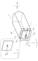
- FIG. 1 is a perspective view schematically showing the main configuration of a headlamp device according to Embodiment 1.
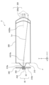
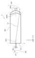
- FIG. FIG. 2 is a side view schematically showing the main configuration of the headlamp device of FIG. 1.
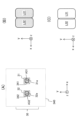
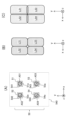
- FIG. (A) is a front view showing the light source part of the headlamp device of FIGS. 1 and 2, and (B) and (C) are views showing an example of the irradiation range divided into four segments. be.
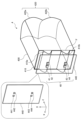
- FIG. 2 is a perspective view schematically showing the main configuration of a headlamp device according to a second embodiment.
- 5 is a side view schematically showing the main structure of the headlamp device of FIG. 4.
- FIG. (A) is a front view showing the light source part of the headlamp device of FIGS.
- FIG. 3 is a perspective view schematically showing the main configuration of a headlamp device according to a third embodiment.
- 8 is a side view schematically showing the main structure of the headlamp device of FIG. 7.
- FIG. (A) is a front view showing the light source part of the headlamp device of FIGS. 7 and 8, and (B) and (C) are views showing an example of the irradiation range divided into two segments.
- FIG. 7 is a perspective view schematically showing the main configuration of a headlamp device according to a fourth embodiment.
- 11 is a side view schematically showing the main structure of the headlamp device of FIG. 10.
- FIG. 7 is a perspective view schematically showing the main structure of a headlamp device according to a fifth embodiment.
- 15 is a side view schematically showing the main structure of the headlamp device of FIG. 14.
- FIG. (A) is a front view showing the light source part of the headlamp device of FIGS.
- FIG. 14 and 15, and (B) and (C) are views showing an example of the irradiation range divided into four segments.
- FIG. 7 is a perspective view schematically showing the main structure of a headlamp device according to a sixth embodiment.
- 18 is a side view schematically showing the main structure of the headlamp device of FIG. 17.
- FIG. (A) is a front view showing the light source part of the headlamp device of FIGS. 17 and 18, and (B) and (C) are views showing an example of the irradiation range divided into two segments. be.
- the headlamp device is, for example, a vehicle headlamp device mounted on a vehicle.
- the vehicle is, for example, a four-wheeled motor vehicle, a three-wheeled motor vehicle, a two-wheeled motor vehicle, or the like.
- the irradiation state of light emitted from the headlamp device is high beam, which is the state during driving.
- the light distribution (i.e., light distribution pattern) of the light emitted from the headlamp device when the illumination state is high beam is different from that of the headlamp when the illumination state is low beam, which is the state when vehicles pass each other. It has a wider range and higher illuminance than the light distribution of light emitted from the lighting device. Therefore, when the illumination state of the headlamp device is high beam, good visibility for the driver of the vehicle equipped with the headlamp device is ensured. However, when the illumination state is high beam, the high beam illumination light may dazzle the driver of a preceding vehicle or an oncoming vehicle.
- the headlamp device performs control to adjust the light distribution of light, for example, ADB (Adaptive Driving Beam) control of the headlamp.
- ADB Adaptive Driving Beam
- the light distribution of the light emitted by the high beam is such that the target area (for example, the area in front excluding the preceding vehicle and oncoming vehicle) becomes the light irradiation area. The distribution is adjusted.
- the headlamp device has one headlamp module. Therefore, in each embodiment, the headlamp device is also referred to as a headlamp module. However, the headlamp device according to each embodiment may include a plurality of headlamp modules.
- the x-axis is a coordinate axis parallel to the left-right direction of the vehicle equipped with the headlamp device. That is, the x-axis direction is the width direction of the vehicle. When facing the front of the vehicle, the left direction is the +x-axis direction, and the right direction is the -x-axis direction.
- the y-axis is a coordinate axis parallel to the vertical direction of the vehicle. The upward direction of the vehicle is the +y-axis direction, and the downward direction of the vehicle is the -y-axis direction.
- the +y-axis side of the vehicle is the empty side
- the -y-axis side is the road surface side.
- the z-axis is a coordinate axis perpendicular to the x-axis and the y-axis.
- the z-axis direction is the direction in which the vehicle travels. In the following description, the +z-axis direction is also referred to as the front.
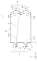
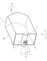
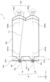
- FIG. 1 is a perspective view schematically showing the main configuration of a headlamp device 1 according to the first embodiment.
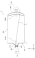
- FIG. 2 is a side view schematically showing the main configuration of the headlamp device 1.
- the headlamp device 1 includes a light source section 10 having a plurality of light sources 11 to 14, and a light guide projection optical element (for example, a lens) having an entrance surface 110 and an exit surface 120.
- a single optical section 100 is provided.
- a plurality of lights emitted from the light emitting surfaces 11a to 14a of the plurality of light sources 11 to 14 enter into the optical section 100 from the entrance surface 110.
- the plurality of lights that have entered the optical section 100 travel within the optical section 100 and are projected from the projection areas 120a and 120b of the exit surface 120 as a plurality of projection lights L11 to L14.
- La indicates an example of a light ray that travels through the optical section 100 and is emitted from the output surface 120.
- the output surface 120 of the optical section 100 has one or more projection areas (here, two projection areas 120a and 120b) through which the plurality of projection lights L11 to L14 respectively pass.
- the optical axes A120a and A120b of the projection areas 120a and 120b of the exit surface 120 may be eccentric with respect to the optical axes A11 to A14 of the plurality of light sources 11 to 14. Note that the configuration of the headlamp device 1 is not limited to that shown in FIGS. 1 and 2.
- the optical axes A120a, A120b being eccentric with respect to the optical axes A11 to A14 means a state in which the optical axes A120a, A120b and the optical axes A11 to A14 do not overlap with each other (that is, in the x direction and the y direction). a state in which the optical axes A120a and A120b are deviated from each other in at least one direction), a state in which the directions of the optical axes A120a and A120b are different from the directions of the optical axes A11 to A14 (that is, a state in which they are tilted), or both of these states.
- the light source unit 10 includes a plurality of light emitting elements as a plurality of light sources 11 to 14.
- the light emitting device is a solid state light source.
- a solid state light source is a directional light source.
- the solid state light source is, for example, a semiconductor light source.
- the light sources 11 to 14 are, for example, light emitting diodes (LEDs).
- the solid-state light source may be an organic electroluminescence light source.
- the light sources 11 to 14 may be light sources that emit light by irradiating excitation light onto a phosphor coated on a flat surface. LEDs are preferable as the light sources 11 to 14 because the modules are small, easy to form into an array, have high brightness, are safe, and are low cost.
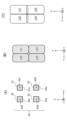
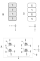
- FIG. 3(A) is a front view showing the light source section 10 of the headlamp device 1
- FIGS. 3(B) and (C) are diagrams showing an example of the irradiation range divided into four segments. be.
- the surfaces of the light sources 11 to 14 facing the +z-axis direction are light emitting surfaces 11a to 14a.
- the light source section 10 includes a plurality (that is, N) of light emitting surfaces 11a to 14a.
- the light emitting surfaces 11a to 14a may be arranged on the same plane (ie, a plane parallel to the xy plane).
- N is 4, but N is not limited to 4. Note that N is an integer of 2 or more.
- the light emitting surfaces 11a and 12a are arranged linearly in the x-axis direction, and the light emitting surfaces 13a and 14a are arranged linearly in the x-axis direction. Further, in the first embodiment, the light emitting surfaces 11a and 13a are arranged in the y-axis direction, and the light emitting surfaces 12a and 14a are arranged in the y-axis direction.
- Each of the light emitting surfaces 11a to 14a has a rectangular shape such as a square, for example. However, each of the light emitting surfaces 11a to 14a is not limited to a rectangular shape. Each of the light emitting surfaces 11a to 14a may have another shape such as a circular shape.
- the optical section 100 is located in the +z-axis direction of the light source section 10.
- the optical section 100 is a light guide projection optical element composed of a single optical component.
- Optical section 100 is composed of a single lens. A plurality of lights emitted from the light emitting surfaces 11a to 14a of the light source section 10 enter the optical section 100.
- the optical section 100 projects projection lights L11 to L14 made up of a plurality of segments forward (in the +z-axis direction).
- the entrance surface 110 of the optical section 100 has, for example, at least one condensing region that condenses the light emitted from the light source section 10 (that is, a region having a condensing function).
- the entrance surface 110 has a plurality of condensing regions 110a, 110b and a plurality of optical axes A110a, A110b.
- the entrance surface 110 of the optical section 100 may have a single light condensing region and its optical axis. In FIGS. 1 and 2, the entrance surface 110 has two light collection areas 110a and 110b.
- the light condensing regions 110a and 110b protrude toward the light source section 10 (that is, toward the ⁇ z-axis direction), and extend in a predetermined extension direction (in the first embodiment, the x-axis direction). It has a convex portion having a top portion (that is, a top portion when the ⁇ z-axis direction is regarded as the height direction). Further, the profiles of the light condensing regions 110a and 110b (for example, an aspherical profile) are arranged such that one side (for example, in the +y-axis direction) with the top of the convex portion (that is, the ridgeline extending in the x-axis direction) sandwiched therebetween.
- the amount of sag that indicates the profile of the light focusing regions 110a, 110b is different from one side to the other with the top of the convex portion in between. and are different from each other.
- the tops of the convex portions have a gentle slope on the +y-axis direction side, and a steep slope on the -y-axis direction side.
- the focal point of the light condensing regions 110a and 110b is, for example, a plane F parallel to the xy plane and on the end face of the optical section 100 facing in the -z axis direction.
- the optical section 100 is, for example, integrally formed of the same material.
- the optical section 100 is made of, for example, transparent resin.
- the optical section 100 is, for example, a light guide/projection optical element whose interior is filled with a refractive material and which guides light incident from an entrance surface 110 and projects it from an output surface 120 .
- it is desirable that the number of optical surfaces of the optical section 100 through which one light beam passes is small.
- the optical surfaces of the optical section 100 through which one light ray passes are two surfaces: the entrance surface 110 and the exit surface 120.
- the entrance surface 110 is provided at the end of the optical section 100 in the -z axis direction.
- the incident surface 110 is arranged at a distance from the light source section 10 in the +y-axis direction of the light source section 10 .
- the entrance surface 110 has, for example, positive power.
- the shape of the entrance surface 110 may be independent of the position in the x-axis direction so as to facilitate manufacturing.
- the expression representing the amount of sag in the x-axis direction of the incident surface 110 may be different from the expression representing the amount of sag in the y-axis direction.
- the formula expressing the amount of sag on the incident surface 110 may be different between a region where y ⁇ 0 and a region where y ⁇ 0, assuming that the y coordinate of the top of the condensing regions 110a and 110b is 0.
- the incident surface 110 (for example, the light condensing regions 110a and 110b) may be a free-form surface.
- the optical axes A120a and A120b of the condensing regions 110a and 110b of the incident surface 110 may be eccentric with respect to the optical axes A11 to A14 of the light sources 11 to 14.
- the entrance surface 110 may be discontinuous. That is, the entrance surface 110 may have a discontinuous portion such as a step.
- each of the light converging regions 110a and 110b all have the same shape.
- the plurality of light condensing regions 110a and 110b may have mutually different shapes.
- the light that has passed through the incident surface 110 (for example, the light that has been condensed by the condensing regions 110a and 110b) is directed toward the front of the vehicle equipped with the headlamp device 1 (+z axis direction).
- the exit surface 120 has at least one projection area that has a projection function. That is, the output surface 120 has a plurality of projection areas 120a, 120b and a plurality of optical axes A120a, A120b. That is, the output surface 120 may have a plurality of projection areas 120a, 120b and a plurality of optical axes A120a, A120b. However, the output surface 120 of the optical section 100 may have a single projection area and its optical axis. In FIGS. 1 and 2, the exit surface 120 has two projection areas 120a and 120b.
- the optical unit 100 also includes projection areas 120a and 120b of the exit surface 120 such that images focused by the light collection regions 110a and 110b of the entrance surface 110 are projected by projection regions 120a and 120b of the exit surface 120, respectively.
- the focal point in may be provided inside the optical section 100.
- the projection areas 120a and 120b of the output surface 120 may be spherical.
- the projection areas 120a and 120b of the output surface 120 may be aspherical.
- the profile of the exit surface 120 in the x-axis direction (for example, an aspherical profile) may be different from the profile in the y-axis direction (for example, an aspherical profile).
- the formula representing the sag amount indicating the profile in the x-axis direction of the output surface 120 is the sag amount indicating the profile in the y-axis direction (for example, an aspherical profile) may be different from the expression representing Moreover, the formula expressing the sag amount of the output surface 120 may be different between the area where y ⁇ 0 and the area where y ⁇ 0, assuming that the y coordinate of the top of the projection areas 120a and 120b is 0. Further, the output surface 120 (for example, the projection areas 120a, 120b) may be a free-form surface.
- the formula representing the sag amount is a known formula that represents the profile of an aspherical surface as a function of the distance from the optical axis.
- the optical axes A120a and A120b of the projection areas 120a and 120b of the output surface 120 are eccentric in at least one of the x-axis direction and the y-axis direction with respect to the optical axes A11 to A14 of the light sources 11 to 14. Further, the headlamp device 1 may be configured such that the optical axes A120a and A120b of the projection areas 120a and 120b of the output surface 120 have different degrees of eccentricity with respect to the optical axis of the corresponding light source.
- the degree of eccentricity (that is, the amount of deviation) of the optical axis A120a of the projection area 120a with respect to the optical axis A11 of the light source 11 (or the optical axis A12 of the light source 12) is such that the optical axis A120b of the projection area 120b is It may be different from the magnitude of eccentricity (that is, the amount of deviation) with respect to the axis A13 (or the optical axis A14 of the light source 14).
- the output surface 120 may have discontinuous portions. That is, the output surface 120 may have a discontinuous portion such as a step.
- the shapes of each projection area 120a and 120b are all the same. However, the shapes of the projection areas 120a and 120b may be different from each other.
- the number of light converging regions 110a, 110b that the entrance surface 110 has and the number of projection regions 120a, 120b that the exit surface 120 has are equal, and the number of light converging regions 110a, 110b and the projection region 120a are equal.
- 120b have a one-to-one correspondence.
- the combination of the light condensing region 110a and the projection region 120a and the combination of the light condensing region 110b and the projection region 120b have the same shape.
- the combination of the light collection area 110a and the projection area 120a and the combination of the light collection area 110b and the projection area 120b may have different shapes.
- the number of optical surfaces of the optical section 100 through which one light beam emitted from the light emitting surface of the light source passes may be three or more.
- Light distribution Figures 3 (B) and (C) show an example of the irradiation range divided into four segments, that is, an example of the light distribution pattern of the headlamp device 1. .
- the light emitted from each of the light emitting surfaces 11a to 14a of the plurality of light sources 11 to 14 passes through the optical section 100 and is projected into different projection lights L11 to L14 (that is, a plurality of segments) in front of the headlamp device 1. ) to illuminate different irradiation ranges.
- the light distribution has, for example, the same number of segments as the number of light emitting surfaces 11a to 14a.
- the light distribution formed by the plurality of projection lights L11 to L14 is directed in a predetermined first direction (for example, the x-axis direction or the y-axis direction) and a second direction orthogonal to the first direction (for example, the y-axis direction).
- the irradiation range includes a plurality of segments arranged in at least one of the axial direction and the x-axis direction.
- the light emitting surface 120 in each of the one or more projection areas 120a, 120b is arranged such that the ends of adjacent segments in the arrangement direction of the plurality of segments touch each other (for example, as shown in FIG. 3(B)).
- the positions and directions of the axes A120a and A120b may be set.
- a plurality of light sources are arranged so that a plurality of lights emitted from light emitting surfaces 11a to 14a of a plurality of light sources 11 to 14 are irradiated to mutually different segments from an exit surface 120 of the optical section 100 as a plurality of projection lights L11 to L14. 11 to 14 and an optical section 100 are formed.
- the output surface 120 of the optical section 100 has a plurality of optical axes.
- Projection lights of adjacent segments (for example, L12 and L14, L14 and L11, and L11 and L13 in FIGS. 3B and 3C) have a projection area 120a having mutually different optical axes A120a and A120b on the exit surface 120, It is desirable that the light be emitted from 120b.
- the intervals between the plurality of segments of the projected light are determined by the eccentricity of the optical axes A120a and A120b of the projection areas 120a and 120b of the output surface 120 with respect to the optical axes A11 to A14 of the light sources 11 to 14, and the distance between the light sources 11 to 14. Determined by size.
- the ends of adjacent segments of the projected light touch so that they partially overlap.
- the optical axes A120a and A120b of the projection areas 120a and 120b of the output surface 120 are eccentric so that the boundaries of the segments touch each other in light distribution (including cases where they partially overlap).
- the boundary of a segment refers to the boundary line where the luminous intensity is 625 cd at the end of the segment. Touching means that both boundary lines of adjacent segments touch, or that both boundary lines are located on adjacent segments.
- intervals between the segments emitted from the projection area including the same optical axis on the output surface 120 are all the same, but the intervals between the segments do not have to be the same.
- the width in at least one of the x-axis direction (horizontal direction of the vehicle) and the y-axis direction (vertical direction of the vehicle) is equal to each other.
- the focal lengths in the projection areas 120a and 120b corresponding to each optical axis are all equal.
- each segment of the light distribution may have unequal widths in at least one of the horizontal and vertical directions.
- the areas of the light emitting surfaces 11a to 14a corresponding to each segment may be different from each other.
- the focal length in the projection area corresponding to each optical axis may be different.
- the optical section 100 is constituted by a single optical element, the focal position of the exit surface 120 with respect to the entrance surface 110 is fixed. Therefore, variations in the position of the optical section 100 have little effect on the light distribution.
- the output surface 120 has a plurality of optical axes A120a and A120b, a light distribution is formed depending on the eccentricity of each of the optical axes A120a and A120b with respect to the optical axes A11 to A14 of the light sources 11 to 14.
- the emission directions of the projection lights L11 to L14 can be arbitrarily designed. In other words, by adjusting the eccentricity of the optical axes A11 to A14 of the light sources 11 to 14 with respect to the optical axes A120a and A120b of the optical section 100, the positions of the segments of the projected light that form the light distribution can be set.
- the distance between adjacent light sources 11 to 14 and the eccentricity of the optical axes A120a and A120b of the light emitting surface 120 with respect to the optical axes A11 to A14 of the light sources 11 to 14 as parameters, it is possible to The size of the interval can be designed in detail. Therefore, the occurrence of uneven brightness of illumination light is reduced.
- adjacent segments among the plurality of segments of the projected light are projected from projection areas 120a and 120b with mutually different optical axes A120a and A120b, as shown in FIGS. 3(B) and 3(C). Since the segments are set to 1, it is possible to reduce the influence of light seepage into adjacent segments on light distribution.
- FIG. 4 is a perspective view schematically showing the main structure of the headlamp device 2 according to the second embodiment.
- FIG. 5 is a side view schematically showing the main configuration of the headlamp device 2.
- the incident surface 110 of the optical section 100 is provided with two condensing regions 110a and 110b having apex extending in the x-axis direction
- the exit surface 120 is provided with two converging regions 110a and 110b.
- projection areas 120a and 120b, which are convex portions, are provided has been described.
- a condensing region 210a which is a convex portion having a single apex extending in the x-axis direction, is provided on the entrance surface 210 of the optical section 200.
- a projection area 220a which is a single convex portion, is provided on the output surface 220.
- the number of projection areas may be two or more as long as it is one or more.
- the headlamp device 2 includes a light source section 20 having a plurality of light sources 21 to 24, and a single optical section 200 that is a light guiding and projecting optical element (for example, a lens) having an entrance surface 210 and an exit surface 220. ing.
- La indicates an example of a light ray that travels through the optical section 200 and is emitted from the output surface 220.
- the plurality of lights that have entered the optical section 200 are projected from the projection area 220a of the output surface 220 as a plurality of projection lights L21 to L24.
- optical axis A220a of the projection area 220a of the output surface 220 is eccentric with respect to the optical axes A21 to A24 of the plurality of light sources 21 to 24.
- FIG. 6(A) is a front view showing the light source section 20 of the headlamp device 2
- FIGS. 6(B) and (C) are diagrams showing an example of the irradiation range divided into four segments. be.
- the surfaces of the light sources 21 to 24 facing the +z-axis direction are light emitting surfaces 21a to 24a.
- the light source section 20 includes a plurality of light emitting surfaces 21a to 24a.
- the light emitting surfaces 21a to 24a are arranged, for example, on the same plane (that is, a plane parallel to the xy plane).
- the light emitting surfaces 21a and 22a are arranged in the x-axis direction
- the light emitting surfaces 23a and 24a are arranged in the x-axis direction.
- the light emitting surfaces 21a and 23a are arranged in the y-axis direction
- the light emitting surfaces 22a and 24a are arranged in the y-axis direction.
- the optical section 200 is located in the +z-axis direction of the light source section 20. A plurality of lights emitted from the light emitting surfaces 21a to 24a of the light source section 20 enter the optical section 200.
- the optical section 200 projects projection lights L21 to L24 made up of a plurality of segments forward (in the +z-axis direction).
- the entrance surface 210 of the optical section 200 has, for example, a single condensing region 210a that condenses the light emitted from the light source section 20.
- the entrance surface 210 has a single condensing region 210a and a single optical axis A210a.
- the entrance surface 210 of the optical section 200 may have a plurality of light condensing regions and their optical axes.
- the focal point of the condensing region 210a is, for example, a plane F parallel to the xy plane and on the end face of the optical section 200 facing in the -z axis direction.
- the shape of the condensing region 210a of the entrance surface 210 is similar to that of the condensing region 110a in the first embodiment.
- the optical section 200 is constituted by a single optical element, the focal position of the exit surface 220 with respect to the entrance surface 210 is fixed. Therefore, variations in the position of the optical section 200 have little effect on the light distribution.
- the distance between segments can be changed.
- the size can be designed in detail.
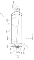
- FIG. 7 is a perspective view schematically showing the main configuration of the headlamp device 3 according to the third embodiment.
- FIG. 8 is a side view schematically showing the main structure of the headlamp device 3.
- the headlamp device 3 includes a light source section 30 having a plurality of light sources 31 and 32, and a light guide projection optical element (for example, a lens) having an entrance surface 310 and an exit surface 320. It includes a single optical section 300 and a shade 340 that is a light shielding member.
- the plurality of lights that have entered the optical section 300 are projected from the projection area 320a of the output surface 320 as a plurality of projection lights L31 and L34.
- La indicates an example of a light ray that travels within the optical section 300 and is emitted from the output surface 320.
- the output surface 320 of the optical section 300 has a projection area 320a through which each of the plurality of projection lights L11 to L14 passes.
- the optical axis A320a of the projection area 320a of the output surface 320 may be eccentric with respect to the optical axes A31 and A34 of the plurality of light sources 31 and 32.
- the configuration of the headlamp device 3 is not limited to that shown in FIGS. 7 and 8.
- the optical axis A320a being eccentric with respect to the optical axes A31 and A32 means that the optical axis A320a and the optical axes A31 and A32 do not overlap with each other (that is, in at least one of the x direction and the y direction). a state in which the optical axis A320a and the optical axes A31 and A32 are oriented differently (that is, a state in which they are tilted), or both of these states.
- the light source section 30 includes a plurality of light emitting elements as a plurality of light sources 31 and 32.
- the light emitting element is the same as that described in Embodiment 1.
- FIG. 9(A) is a front view showing the light source section 30 of the headlamp device 3, and FIGS. 9(B) and (C) are diagrams showing an example of the irradiation range divided into two segments.
- the surfaces of the light sources 31 and 32 facing the +z-axis direction are light emitting surfaces 31a and 32a.
- the light source section 30 includes a plurality (that is, N) of light emitting surfaces 31a and 32a.
- the light emitting surfaces 31a and 32a may be arranged on the same plane (that is, a plane parallel to the xy plane).
- N is 2, but N is not limited to 2.
- N is an integer of 2 or more.
- the light emitting surfaces 31a and 32a are arranged in the x-axis direction.
- the shapes of the light emitting surfaces 31a and 32a are the same as those described in the first embodiment.
- a shade 340 is installed in the +z-axis direction of the light source section 30, as shown in FIGS. 7 and 8.
- the shade 340 has openings 341 and 342 facing the light emitting surfaces 31a and 32a of the light sources 31 and 32, and contributes to light distribution by blocking the ends of the light emitted from the light emitting surfaces 31a and 32a in the x direction. This limits the luminous flux.
- the shade 340 has a structure that limits the size of the luminous flux diameter of the plurality of lights emitted from the light emitting surfaces 31a and 32a of the plurality of light sources 31 and 32, respectively.
- the light flux contributing to the light distribution may be limited by blocking both the x-direction end and the y-direction end of the light emitted from the light emitting surfaces 31a, 32a of each light source 31, 32.
- the shape of the openings 341 and 342 of the shade 340 is, for example, rectangular.
- the shape of the openings 341 and 342 of the shade 340 is not limited to a rectangle.
- the shapes of the openings 341 and 342 may be other shapes, such as the openings shown in FIG. 13(A), which will be described later.
- the shade 340 is made of metal such as stainless steel, for example.
- the area of the incident area of the incident light that passes through any one of the plurality of apertures 341 and 342 among the plurality of light sources and hits the entrance surface 310 is determined by the area of the light source 31 corresponding to the incident light among the plurality of light sources 31 and 32. It is smaller than the area of the light emitting surface 31a or 32a of 32.
- the optical section 300 is located in the +z-axis direction of the light source section 30.
- the optical section 300 is a light guide projection optical element composed of a single optical component.
- Optical section 300 is composed of a single lens.
- a plurality of lights emitted from the light emitting surfaces 31 a and 32 a of the light source section 30 enter the optical section 300 .
- the optical section 300 projects projection light consisting of a plurality of segments forward (in the +z-axis direction).
- the plurality of lights emitted from the light emitting surfaces 31a and 32a of the plurality of light sources 31 and 32 pass through two optical surfaces among the plurality of optical surfaces of the optical section 300, and are projected as a plurality of projection lights L31 and L32. be done.
- the entrance surface 310 of the optical section 300 has, for example, at least one condensing region that condenses the light emitted from the light source section 30. That is, the incident surface 310 has a light condensing region 310a and an optical axis A310a.
- the focal point of the condensing region 310a is, for example, a plane F parallel to the xy plane and on the end face of the optical section 300 facing in the -z axis direction. Note that the incident surface 310 may not include a light condensing region.
- the optical section 300 is, for example, integrally formed of the same material.
- the optical section 300 is made of, for example, transparent resin.
- the optical section 300 is, for example, a light guide/projection optical element whose interior is filled with a refractive material and which guides light incident from an entrance surface 310 and projects it from an output surface 320 .
- the optical surfaces of the optical section 300 through which one light beam passes are two surfaces: an entrance surface 310 and an exit surface 320.
- the entrance surface 310 is provided at the end of the optical section 300 in the -z axis direction.
- the incident surface 310 is arranged at a distance from the light source section 30 in the +y-axis direction of the light source section 30 .
- the entrance surface 310 has, for example, positive power.
- the shape of the entrance surface 310 may be independent of the position in the x-axis direction to facilitate manufacturing.
- the expression representing the amount of sag in the x-axis direction of the incident surface 310 may be different from the expression representing the amount of sag in the y-axis direction.
- the formula expressing the amount of sag on the incident surface 310 may be different between a region where y ⁇ 0 and a region where y ⁇ 0, assuming that the y-coordinate of the top of the condensing region 310a is 0.
- the incident surface 310 (for example, the light condensing region 310a) may be a free-form surface.
- the optical axis A320a of the condensing region 310a of the incident surface 310 may be eccentric with respect to the optical axes A31 and A32 of the light sources 31 and 32.
- the entrance surface 310 may be discontinuous. That is, the entrance surface 310 may have a discontinuous portion such as a step.
- the light that has passed through the entrance surface 310 (for example, the light that has been collected by the condensing region 310a) is projected by the projection region 320a of the exit surface 320 into an area in front of the vehicle equipped with the headlamp device 3 (in the +z-axis direction). is projected on.
- the exit surface 320 has at least one projection area that has a projection function. That is, the output surface 320 has a projection area 320a and its optical axis A320a.
- the plurality of lights emitted from the light emitting surfaces 31a and 32a of the plurality of light sources 31 and 32 are projected onto individual irradiation areas as projection lights L31 and L32 via the optical section 300, respectively.
- the optical section 300 is arranged so that the focal point in the projection area 320a of the output surface 320 is set in the optical section so that the image condensed by the condensing area 310a of the input surface 310 is respectively projected by the projection area 320a of the output surface 320.
- 300 may be provided.
- the projection area 320a of the output surface 320 may be a spherical surface.
- the projection area 320a of the output surface 320 may be an aspherical surface.
- the expression representing the amount of sag in the x-axis direction of the output surface 320 may be different from the expression representing the amount of sag in the y-axis direction.
- the formula expressing the amount of sag of the output surface 320 may be different between an area where y ⁇ 0 and an area where y ⁇ 0, assuming that the y coordinate of the top of the projection area 320a is 0.
- the output surface 320 (for example, the projection area 320a) may be a free-form surface.
- the optical axis A320a of the projection area 320a of the output surface 320 is eccentric with respect to the optical axes A31 and A32 of the light sources 31 and 32 in at least one of the x-axis direction and the y-axis direction.
- the output surface 320 may have discontinuous portions. That is, the output surface 320 may have a discontinuous portion such as a step.
- the shapes of each projection area 320a are all the same. However, the shapes of the projection areas 320a may be different from each other.
- the number of optical surfaces of the optical section 300 through which one ray emitted from the light emitting surface of the light source passes may be three or more.
- FIGS. 9(B) and (C) show an example of the irradiation range divided into two segments, that is, an example of the light distribution pattern of the headlamp device 3. .
- the light emitted from each of the light emitting surfaces 31a and 32a of the plurality of light sources 31 and 32 passes through the optical section 300 and is projected into different projection lights L31 and L32 (i.e., a plurality of segments) in front of the headlamp device 3. ) to illuminate different irradiation ranges.
- the light distribution has, for example, the same number of segments as the number of light emitting surfaces 31a and 32a.
- the interval between the plurality of segments of the projected light L31, L32 is determined by the eccentricity of the light sources 31, 32 with respect to the optical axis A31, A32 in the optical axis A320a of the projection area 320a of the output surface 320, and the interval between the light sources 31, 32. determined by.
- the optical axis A320a of the projection area 320a of the output surface 320 is eccentric so that the boundaries of the segments touch each other in light distribution (including cases where they partially overlap).
- the boundary of the segment represents the boundary line where the luminous intensity is 625 cd at the end of the segment. Touching means that both boundary lines of adjacent segments touch, or that both boundary lines are located on adjacent segments.
- the distance between adjacent light sources 31 and 32, the position of openings 341 and 342 of shade 340, and the eccentricity of optical axis A320a of output surface 320 with respect to optical axes A31 and A32 of light sources 31 and 32 By using it as a parameter, the size of the interval between segments can be designed in detail.
- the light flux contributing to the light distribution is restricted by the shade 340, it is possible to reduce the degree of influence that appears on the projected lights L31 and L32 due to variations in the arrangement of the light sources 31 and 32 in the light distribution. .
- the curvature in the x-axis direction can be reduced in the equation expressing the amount of sag in the x-axis direction for the entrance surface 310 of the optical section 300. Can be done. Moreover, thereby, the shape of the optical section 300 can be simplified.
- the direction in which the width of each of the projected lights L31 and L32 is narrowed by the shade 340 is not limited to the x-axis direction, but may be the y-axis direction or both the x-axis and y-axis directions.
- the third embodiment is the same as the first or second embodiment.
- FIG. 10 is a perspective view schematically showing the main structure of the headlamp device 4 according to the fourth embodiment.
- FIG. 11 is a side view schematically showing the main structure of the headlamp device 4.
- the headlight device 4 includes a light source section 40 having a plurality of light sources 41 to 44, a shade 440 as a light shielding member, and a light guide having an entrance surface 410 and an exit surface 420.
- a single optical section 400 that is a projection optical element (for example, a lens) is provided.
- the plurality of lights emitted from the light emitting surfaces of the plurality of light sources 41 to 44 respectively pass through the openings 441 to 444 of the shade 440, proceed toward the entrance surface 410, and enter the optical section 400 from the entrance surface 410. .
- the plurality of lights that have entered the optical section 400 are projected from the projection areas 420a and 420b of the output surface 420 as a plurality of projection lights L41 to L44.
- La indicates an example of a light ray that travels through the optical section 400 and is emitted from the output surface 420.
- the output surface 420 of the optical section 400 has one or more projection areas (here, two projection areas 420a and 420b) through which the plurality of projection lights L41 to L44 respectively pass.
- the optical axes A420a and A420b of the projection areas 420a and 420b of the output surface 420 may be eccentric with respect to the optical axes A41 to A44 of the plurality of light sources 41 to 44. Note that the configuration of the headlamp device 4 is not limited to that shown in FIGS. 10 and 11.
- the optical axes A420a, A420b being eccentric with respect to the optical axes A41 to A44 means a state in which the optical axes A420a, A420b and the optical axes A41 to A44 do not overlap with each other (that is, in the x direction and the y direction). a state in which the optical axes A420a and A420b are deviated from each other in at least one direction), a state in which the directions of the optical axes A420a and A420b are different from the directions of the optical axes A41 to A44 (that is, a state in which they are tilted), or both of these states.
- the light source section 40 includes a plurality of light emitting elements as a plurality of light sources 41 to 44.
- FIG. 12(A) is a front view showing the light source section 40 of the headlamp device 4, and FIGS. 12(B) and (C) are diagrams showing an example of the irradiation range divided into four segments. be.
- the surfaces of the light sources 41 to 44 facing the +z-axis direction are light emitting surfaces 41a to 44a.
- the light source section 40 includes a plurality (that is, N) of light emitting surfaces 41a to 44a.
- the light emitting surfaces 41a to 44a may be arranged on the same plane (ie, a plane parallel to the xy plane).
- N is 4, but N is not limited to 4. Note that N is an integer of 2 or more.
- the light emitting surfaces 41a and 42a are arranged linearly in the x-axis direction, and the light emitting surfaces 43a and 44a are arranged linearly in the x-axis direction. Furthermore, in the fourth embodiment, the light emitting surfaces 41a and 43a are arranged in the y-axis direction, and the light emitting surfaces 42a and 44a are arranged in the y-axis direction.
- Each of the light emitting surfaces 41a to 44a has a rectangular shape such as a square, for example. However, each of the light emitting surfaces 41a to 44a is not limited to a rectangular shape. Each of the light emitting surfaces 41a to 44a may have another shape such as a circular shape.
- ⁇ Shade 440> In the headlamp device 4, a shade 440 is installed in the +z-axis direction of the light source section 30, as shown in FIGS. 10 and 11.
- the shade 440 has openings 441 to 444 facing the light emitting surfaces 41a to 44a of the light sources 41 to 44, and contributes to light distribution by blocking the ends of the light emitted from the light emitting surfaces 41a to 44a in the x direction. This limits the luminous flux.
- the shade 440 has a structure that limits the size of the beam diameter of the plurality of lights emitted from the light emitting surfaces 41a to 44a of the plurality of light sources 41 to 44, respectively.
- the shade 440 limits the luminous flux that contributes to light distribution by blocking both the ends in the x direction and the ends in the y direction of the light emitted from the light emitting surfaces 41a to 44a of the light sources 41 to 44. It's okay.
- the shapes of the openings 441 to 444 of the shade 440 are, for example, rectangular.
- the shapes of the openings 441 to 444 of the shade 440 are not limited to rectangular shapes.
- the optical section 400 is located in the +z-axis direction of the light source section 40.
- the optical section 400 is a light guide projection optical element composed of a single optical component.
- Optical section 400 is composed of a single lens. A plurality of lights emitted from the light emitting surfaces 41a to 44a of the light source section 40 enter the optical section 400.
- the optical section 400 projects projection lights L41 to L44 made up of a plurality of segments forward (in the +z-axis direction).
- the entrance surface 410 of the optical section 400 has, for example, at least one condensing region that condenses the light emitted from the light source section 40.
- the entrance surface 410 has a plurality of light condensing regions 410a, 410b and a plurality of optical axes A410a, A410b.
- the entrance surface 110 of the optical section 100 may have a single light condensing region and its optical axis. In FIGS. 10 and 11, the entrance surface 110 has two light condensing regions 410a and 410b.
- the focal point of the light condensing regions 410a and 410b is, for example, a plane F parallel to the xy plane and located on the end face of the optical section 400 facing in the -z axis direction. Note that the incident surface 410 may not include a light condensing region.
- the optical section 400 is, for example, integrally formed of the same material.
- the optical section 400 is made of, for example, transparent resin.
- the optical section 400 is, for example, a light guide/projection optical element whose interior is filled with a refractive material and which guides light incident from an entrance surface 410 and projects it from an output surface 420 .
- it is desirable that the number of optical surfaces of the optical section 400 through which one light beam passes is small.
- the entrance surface 410 is provided at the end of the optical section 400 in the -z axis direction.
- the incident surface 410 is arranged in the +y-axis direction of the light source section 40 and in the +y-axis direction of the shade 440 with a space therebetween.
- the entrance surface 410 has, for example, positive power.
- the shape of the entrance surface 410 is the same as the shape of the entrance surface 110 in the first embodiment.
- the light that has passed through the incident surface 410 (for example, the light that has been condensed by the condensing regions 410a and 410b) is directed toward the front of the vehicle equipped with the headlamp device 4 (+z axis direction).
- the exit surface 420 has at least one projection area that has a projection function. That is, the output surface 420 has a plurality of projection areas 420a, 420b and a plurality of optical axes A420a, A420b. For example, the output surface 420 has a plurality of projection areas 420a, 420b and a plurality of optical axes A420a, A420b.
- the output surface 420 of the optical section 400 may have a single projection area and its optical axis.
- the output surface 420 has, for example, positive power.
- the shape of the output surface 420 is the same as the shape of the output surface 120 in the first embodiment.
- FIGS. 12(B) and (C) show an example of the irradiation range divided into four segments, that is, an example of the light distribution pattern of the headlamp device 4. .
- the light emitted from each of the light emitting surfaces 11a to 14a of the plurality of light sources 41 to 44 passes through the openings 441 to 444 of the shade 440, passes through the optical section 400, and is directed to the front of the headlamp device 4.
- Different projection lights L41 to L44 ie, a plurality of segments
- the light distribution has, for example, the same number of segments as the number of light emitting surfaces 41a to 44a.
- the output surface 420 of the optical section 400 has a plurality of optical axes. It is desirable that the projection lights of adjacent segments are emitted from projection areas 420a and 420b having mutually different optical axes A420a and A420b on the output surface 420.
- the intervals between the plurality of segments of the projected light are determined by the eccentricity of the optical axes A420a and A420b of the projection areas 420a and 420b of the output surface 420 with respect to the optical axes A41 to A44 of the light sources 41 to 44, and the distance between the light sources 41 to 44. Determined by size.
- the optical axes A420a and A420b of the projection areas 420a and 420b of the output surface 420 are eccentric so that the boundaries of the segments touch each other in light distribution (including cases where they partially overlap).
- intervals between the segments emitted from the projection area including the same optical axis on the output surface 420 are all the same, but the intervals between the segments do not have to be the same.
- the width in at least one of the x-axis direction (horizontal direction of the vehicle) and the y-axis direction (vertical direction of the vehicle) is equal to each other.
- the focal lengths in the projection areas 420a and 420b corresponding to each optical axis are all equal.
- each segment of the light distribution may have unequal widths in at least one of the horizontal and vertical directions.
- the areas of the light emitting surfaces 41a to 44a corresponding to each segment may be different from each other.
- the focal lengths in the projection areas corresponding to each optical axis may be different.
- the distance between adjacent light sources 41 to 44, the positions of openings 441 to 444 of shade 440, and the eccentricity of optical axes A420a and A420b of output surface 420 with respect to optical axes A41 to A44 of light sources 41 to 44 By using as a parameter, the size of the interval between segments can be designed in detail.
- the width of each of the projected lights L41 to L44 using the shade 440 it is possible to reduce the curvature in the x-axis direction in the equation expressing the amount of sag in the x-axis direction for the entrance surface 410 of the optical section 400. Can be done. Moreover, thereby, the shape of the optical section 400 can be simplified. Note that the direction in which the width of each of the projected lights L41 to L44 is narrowed by the shade 440 is not limited to the x-axis direction, but may be the y-axis direction or both the x-axis and y-axis directions.
- adjacent segments among the plurality of segments of the projection lights L41 to L44 are projected from projection areas 420a and 420b of mutually different optical axes A420a and A420b, as shown in FIGS. 12(B) and 12(C). Since the projected light segments are segmented, the influence of light seepage into adjacent segments on light distribution can be reduced.
- Embodiment 4 is the same as any of Embodiments 1 to 3.
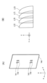
- FIG. 13A is a perspective view schematically showing a shade 740 as a light shielding member of a headlamp device according to a modification of the fourth embodiment.
- FIG. 13(B) is a diagram showing an example of an irradiation range divided into four segments when the shade 740 is used.
- a headlamp device according to a modification of the fourth embodiment is one in which the shade 440 of the headlamp device 4 shown in FIG. 10 is replaced with a shade 740 shown in FIG. 13(A).
- the shade 740 has openings 741 to 744 that are through holes.
- the shape of the openings 741 to 744 increases in width in a direction perpendicular to the predetermined direction (in the illustrated example, the width in the x-axis direction) as it advances in a predetermined direction (in the illustrated example, the ⁇ y-axis direction). It has a narrow shape. In other words, the shapes of the openings 741 to 744 are such that the width gradually narrows in a predetermined direction.
- the shape of the openings 741 to 744 is a shape in which the hypotenuse (that is, the longest side) of a right triangle is bulged into an arc shape (that is, a shape that is outwardly convex). However, the shapes of the openings 741 to 744 may be other shapes.
- the shapes of the openings 741 to 744 may be other shapes in which the width in the direction orthogonal to a predetermined direction becomes narrower as the openings advance in a predetermined direction.
- the number of openings 741 to 744 is not limited to four.
- the shapes and sizes of the openings 741 to 744 are the same, but they can be made to have different shapes and sizes depending on the required light distribution. It is.
- FIG. 14 is a perspective view schematically showing the main structure of a headlamp device 5 according to the fifth embodiment.
- FIG. 15 is a side view schematically showing the main configuration of the headlamp device 5.
- the incident surface 410 of the optical section 400 is provided with two convex condensing regions 410a and 410b having apexes extending in the An example in which projection areas 420a and 420b, which are shaped parts, are provided has been described.
- a single convex condensing region 510a is provided on the entrance surface 510 of the optical section 500, and a single condensing region 510a is provided on the exit surface 520.
- a projection area 520a which is a convex portion, is provided will be described.
- the headlamp device 5 includes a light source section 50 having a plurality of light sources 51 to 54, a shade 540 as a light shielding member, and a unit that is a light guiding and projecting optical element (for example, a lens) having an entrance surface 510 and an exit surface 520. 1 optical section 500.
- a plurality of lights emitted from the light emitting surfaces of the plurality of light sources 51 to 54 pass through openings 541 to 544 of the shade 540, respectively, and enter the optical section 500 from the entrance surface 510.
- the shade 540 has a structure that limits the size of the beam diameter of the plurality of lights emitted from the light emitting surfaces 51a to 54a of the plurality of light sources 51 to 54, respectively.
- the plurality of lights that have entered the optical section 500 are projected from the projection area 520a of the output surface 520 as a plurality of projection lights L51 to L54.
- La indicates an example of a light ray that travels through the optical section 500 and is emitted from the output surface 520.
- the shapes of the openings 541 to 542 may be other shapes, such as the opening shown in FIG. 13(A), for example.
- optical axis A520a of the projection area 520a of the output surface 520 is eccentric with respect to the optical axes A51 to A54 of the plurality of light sources 51 to 54.
- FIG. 16(A) is a front view showing the light source section 50 of the headlamp device 5, and FIGS. 16(B) and (C) are diagrams showing an example of the irradiation range divided into four segments.
- the surfaces of the light sources 51 to 54 facing the +z-axis direction are light emitting surfaces 51a to 54a.
- the light source section 50 includes a plurality of light emitting surfaces 51a to 54a.
- the light emitting surfaces 51a to 54a are arranged, for example, on the same plane (that is, a plane parallel to the xy plane).
- light emitting surfaces 51a and 52a are arranged in the x-axis direction
- light emitting surfaces 53a and 54a are arranged in the x-axis direction.
- the light emitting surfaces 51a and 53a are arranged in the y-axis direction
- the light emitting surfaces 52a and 54a are arranged in the y-axis direction.
- the optical section 500 is located in the +z-axis direction of the light source section 50. A plurality of lights emitted from the light emitting surfaces 51a to 54a of the light source section 50 enter the optical section 500.
- the optical section 500 projects projection light consisting of a plurality of segments forward (in the +z-axis direction).
- the entrance surface 510 of the optical section 500 has, for example, a single condensing region 510a that condenses the light emitted from the light source section 50.
- the entrance surface 510 has a single condensing region 510a and a single optical axis A510a.
- the entrance surface 510 of the optical section 500 may have a plurality of light condensing regions and their optical axes.
- the focal point of the condensing region 510a is, for example, a plane F parallel to the xy plane and on the end face of the optical section 500 facing in the -z axis direction.
- the shape of the condensing region 510a of the entrance surface 510 is similar to that of the condensing region in the first to fourth embodiments.
- the optical section 500 is configured by a single optical element, the focal position of the exit surface 520 with respect to the entrance surface 510 is fixed. Therefore, variations in the position of the optical section 500 have little effect on the light distribution.
- the distance between adjacent light sources 51 to 54, the position of the openings 541 to 544 of the shade 540, and the eccentricity of the optical axis A520a of the exit surface 520 with respect to the optical axes A51 to A54 of the light sources 51 to 54 By changing this as a parameter, the size of the interval between segments can be designed in detail.
- the light flux contributing to the light distribution is restricted by the shade 540, it is possible to reduce the degree of influence that appears on the projected lights L51 and L52 due to variations in the arrangement of the light sources 51 and 52 in the light distribution. .
- Embodiment 5 is the same as any of Embodiments 1 to 4.
- FIG. 17 is a perspective view schematically showing the main structure of a headlamp device 6 according to the sixth embodiment.
- FIG. 18 is a side view schematically showing the main structure of the headlamp device 6.
- the headlamp device 6 includes a light source section 60 having a plurality of light sources 61 and 62, and a light guide projection optical element (for example, a lens) having an entrance surface 610 and an exit surface 620.
- a single optical section 600 is provided.
- the shade 340 limits the width of the plurality of lights emitted from the light emitting surfaces of the light sources 31 and 32, but in the sixth embodiment, as the plurality of light sources 61 and 62, It uses a light emitting element whose width of emitted light is limited. That is, in the sixth embodiment, each of the plurality of light sources 61 and 62 has a structure that limits the size of the luminous flux diameter of the plurality of lights emitted from the respective light emitting surfaces. A plurality of lights emitted from the light sources 61 and 62 travel toward the entrance surface 410 and enter the optical section 600 from the entrance surface 610.
- the plurality of lights that have entered the optical section 600 are projected from the projection areas 620a and 620b of the output surface 620 as a plurality of projection lights L61 and L62.
- La indicates an example of a light ray that travels within the optical section 600 and is emitted from the output surface 620.
- FIG. 19(A) is a front view showing the light source section 60 of the headlamp device 6, and FIGS. 19(B) and (C) are diagrams showing an example of the irradiation range divided into two segments.
- the surfaces of the light sources 61 and 62 facing the +z-axis direction are light emitting surfaces 61a and 62a.
- the light source section 60 includes a plurality of light emitting surfaces 61a and 62a.
- the light emitting surfaces 61a and 62a are arranged, for example, on the same plane (that is, a plane parallel to the xy plane).
- light emitting surfaces 61a and 62a are arranged in the x-axis direction.
- the optical section 600 is located in the +z-axis direction of the light source section 60. A plurality of lights emitted from the light emitting surfaces 61 a and 62 a of the light source section 60 enter the optical section 600 .
- the optical section 600 projects projection lights L61 and L62 consisting of a plurality of segments forward (in the +z-axis direction).
- the entrance surface 610 of the optical section 600 does not include a region that condenses the light emitted from the light source section 60.
- the optical section 600 may include a condensing region similar to that in the second embodiment.
- the intervals between the plurality of segments of the projected lights L61 and L62 are determined by the eccentricity of the light sources 61 and 62 with respect to the optical axes A61 and A62 in the optical axis A620a of the projection area 620a of the output surface 620, and the magnitude of the interval between the light sources 61 and 62. determined by.
- the optical axis A620a of the projection area 620a of the output surface 620 is eccentric so that the boundaries of the segments touch each other in light distribution (including cases where they partially overlap).
- the optical section 600 is configured by a single optical element, the focal position of the exit surface 620 with respect to the entrance surface 610 is fixed. Therefore, variations in the position of the optical section 600 have little effect on the light distribution.
- the distance between the segments can be changed.
- the size can be designed in detail.
- Embodiment 6 is the same as any of Embodiments 1 to 5.
- 1-6 Headlight device 10, 20, 30, 40, 50, 60 Light source section, 11-14, 21-24, 31, 32, 41-44, 51-54, 61, 62 Light source, 11a-14a , 21a to 24a, 31a, 32a, 41a to 44a, 51a to 54a, 61a, 62a Light emitting surface, 100, 200, 300, 400, 500, 600 Optical section (lens), 110, 210, 310, 410, 510, 610 Incident surface, 110a, 110b, 210a, 310a, 410a, 410b, 510a Condensing region, 120, 220, 320, 420, 520, 620 Output surface, 120a, 120b, 220a, 320a, 420a, 420b, 520 a, 620a Projection area, 340, 440, 540, 740 Shade (light shielding member), 341, 342, 441-444, 541-544, 741-744 Opening, A11-A14, A21
Landscapes
- Engineering & Computer Science (AREA)
- General Engineering & Computer Science (AREA)
- Non-Portable Lighting Devices Or Systems Thereof (AREA)
Priority Applications (2)
| Application Number | Priority Date | Filing Date | Title |
|---|---|---|---|
| PCT/JP2022/025446 WO2024003968A1 (ja) | 2022-06-27 | 2022-06-27 | 前照灯装置 |
| JP2024530079A JP7646088B2 (ja) | 2022-06-27 | 2022-06-27 | 前照灯装置 |
Applications Claiming Priority (1)
| Application Number | Priority Date | Filing Date | Title |
|---|---|---|---|
| PCT/JP2022/025446 WO2024003968A1 (ja) | 2022-06-27 | 2022-06-27 | 前照灯装置 |
Publications (1)
| Publication Number | Publication Date |
|---|---|
| WO2024003968A1 true WO2024003968A1 (ja) | 2024-01-04 |
Family
ID=89381779
Family Applications (1)
| Application Number | Title | Priority Date | Filing Date |
|---|---|---|---|
| PCT/JP2022/025446 Ceased WO2024003968A1 (ja) | 2022-06-27 | 2022-06-27 | 前照灯装置 |
Country Status (2)
| Country | Link |
|---|---|
| JP (1) | JP7646088B2 (cg-RX-API-DMAC7.html) |
| WO (1) | WO2024003968A1 (cg-RX-API-DMAC7.html) |
Citations (2)
| Publication number | Priority date | Publication date | Assignee | Title |
|---|---|---|---|---|
| JP2009128659A (ja) * | 2007-11-26 | 2009-06-11 | Toshiba Corp | 表示装置及びそれを用いた移動体 |
| WO2016190165A1 (ja) * | 2015-05-22 | 2016-12-01 | 三菱電機株式会社 | 前照灯モジュール及び前照灯装置 |
-
2022
- 2022-06-27 JP JP2024530079A patent/JP7646088B2/ja active Active
- 2022-06-27 WO PCT/JP2022/025446 patent/WO2024003968A1/ja not_active Ceased
Patent Citations (2)
| Publication number | Priority date | Publication date | Assignee | Title |
|---|---|---|---|---|
| JP2009128659A (ja) * | 2007-11-26 | 2009-06-11 | Toshiba Corp | 表示装置及びそれを用いた移動体 |
| WO2016190165A1 (ja) * | 2015-05-22 | 2016-12-01 | 三菱電機株式会社 | 前照灯モジュール及び前照灯装置 |
Also Published As
| Publication number | Publication date |
|---|---|
| JP7646088B2 (ja) | 2025-03-14 |
| JPWO2024003968A1 (cg-RX-API-DMAC7.html) | 2024-01-04 |
Similar Documents
| Publication | Publication Date | Title |
|---|---|---|
| JP7274626B2 (ja) | ライトガイドを備えた自動車両用の照明装置 | |
| JP7474116B2 (ja) | 光学ユニット、及びそれを備えた車両用灯具 | |
| JP6689198B2 (ja) | 灯具ユニットおよび車両用前照灯 | |
| JP6709655B2 (ja) | 車両用灯具、および当該車両用灯具を備えた車両 | |
| JP6383043B2 (ja) | 前照灯モジュール | |
| JP6132684B2 (ja) | 車両用灯具 | |
| EP2280214B1 (en) | Vehicular lighting equipment | |
| JP6045719B2 (ja) | 前照灯モジュール及び前照灯装置 | |
| CN112805500A (zh) | 车辆用灯具 | |
| JP5475395B2 (ja) | 車両用灯具 | |
| CN100585269C (zh) | 具有非对称准直器的led准直器元件 | |
| EP2500628B1 (en) | Vehicle headlamp | |
| CN102901021A (zh) | 车辆用灯具 | |
| JP4982269B2 (ja) | 車両用照明灯具 | |
| JP2019075232A (ja) | 車両用灯具 | |
| JP7023354B2 (ja) | 光照射装置 | |
| WO2016162921A1 (ja) | 前照灯用光源および前照灯 | |
| WO2016190165A1 (ja) | 前照灯モジュール及び前照灯装置 | |
| JP6630112B2 (ja) | 車両用灯具 | |
| CN117999436A (zh) | 车辆用灯具 | |
| JP6937121B2 (ja) | 灯具 | |
| JP7186570B2 (ja) | 車両用灯具 | |
| JP5692520B2 (ja) | 灯具ユニット | |
| EP3489083B1 (en) | Vehicle headlight | |
| JP6546284B2 (ja) | 灯具 |
Legal Events
| Date | Code | Title | Description |
|---|---|---|---|
| 121 | Ep: the epo has been informed by wipo that ep was designated in this application |
Ref document number: 22949247 Country of ref document: EP Kind code of ref document: A1 |
|
| ENP | Entry into the national phase |
Ref document number: 2024530079 Country of ref document: JP Kind code of ref document: A |
|
| NENP | Non-entry into the national phase |
Ref country code: DE |
|
| 122 | Ep: pct application non-entry in european phase |
Ref document number: 22949247 Country of ref document: EP Kind code of ref document: A1 |