WO2023286804A1 - カニューレ保護アッセンブリ - Google Patents
カニューレ保護アッセンブリ Download PDFInfo
- Publication number
- WO2023286804A1 WO2023286804A1 PCT/JP2022/027554 JP2022027554W WO2023286804A1 WO 2023286804 A1 WO2023286804 A1 WO 2023286804A1 JP 2022027554 W JP2022027554 W JP 2022027554W WO 2023286804 A1 WO2023286804 A1 WO 2023286804A1
- Authority
- WO
- WIPO (PCT)
- Prior art keywords
- cannula
- protection assembly
- cannula protection
- opening
- frame
- Prior art date
- Legal status (The legal status is an assumption and is not a legal conclusion. Google has not performed a legal analysis and makes no representation as to the accuracy of the status listed.)
- Ceased
Links
Images




Classifications
-
- A—HUMAN NECESSITIES
- A61—MEDICAL OR VETERINARY SCIENCE; HYGIENE
- A61M—DEVICES FOR INTRODUCING MEDIA INTO, OR ONTO, THE BODY; DEVICES FOR TRANSDUCING BODY MEDIA OR FOR TAKING MEDIA FROM THE BODY; DEVICES FOR PRODUCING OR ENDING SLEEP OR STUPOR
- A61M16/00—Devices for influencing the respiratory system of patients by gas treatment, e.g. ventilators; Tracheal tubes
- A61M16/04—Tracheal tubes
Definitions
- the present invention relates to cannula protection assemblies.
- a flexible and semi-rigid material is formed into a cylinder or other cylindrical shape, the inner and outer sides are flat or wavy or have other shapes, and several grooves are provided around the outer circumference. Cover it with gauze and fix it by inserting a rubber band into it. Form the lower bottom surface flat or curved to match the throat.
- a separable tracheal cannula mask characterized in that the entire cannula can be wrapped and worn without touching the cannula, and it is described that gauze can be changed even by family members.
- Patent Document 1 it takes time and effort to cut the gauze into a specific size, and the gauze protects the opening of the cannula exposed to the outside of the body. There is a problem that the intrusion of microscopic substances such as viruses and bacteria cannot be sufficiently prevented.
- the gauze of the invention described in Patent Document 1 In order to prevent the invasion of viruses and bacteria floating in the air, it is necessary to replace the gauze of the invention described in Patent Document 1 with a material having a high filtering function. There is a problem that it is difficult to obtain a material that can be fixed and has a high filter function.
- the ventilation part having the ventilation function is only the cylindrical or tubular opening covered with gauze, so the patient breathing through the cannula cannot breathe. There was a problem that it became difficult.
- the problem to be solved by the present invention is to provide a cannula protection assembly that can prevent the invasion of viruses floating in the air with simple work.
- a cannula protection assembly for protecting an incision or an externally exposed opening of a cannula inserted into the incision comprising: a frame surrounding the incision or the externally exposed cannula; or a cannula protection assembly opening arranged at a position corresponding to the opening of the cannula exposed outside the body; Cannula protection assembly.
- ⁇ 3> The cannula protection assembly according to ⁇ 1> or ⁇ 2> above, wherein the cannula protection assembly opening has an opening diameter larger than that of the opening of the incision or cannula.
- ⁇ 4> The cannula protection assembly according to any one of ⁇ 1> to ⁇ 3> above, wherein the frame or the connecting portion has a through hole through which a holder for fixing the cannula protection assembly to the neck is inserted.
- ⁇ 5> The cannula protection assembly according to any one of ⁇ 1> to ⁇ 4> above, wherein the plurality of arms are radially arranged from the cannula protection assembly opening toward the frame.
- ⁇ 6> The cannula protection assembly according to any one of ⁇ 1> to ⁇ 5> above, wherein a protective sheet covering the cannula protection assembly can be detachably fixed.
- a protective sheet covering the cannula protection assembly can be detachably fixed.
- the protective sheet fixing means includes a protective sheet clamping body that clamps the protective sheet.
- the protective sheet fixing means has a gap between the connecting part and the protective sheet for inserting the protective sheet, and includes a frame protruding part that protrudes from the frame toward the cannula protection assembly opening.
- the protective sheet fixing means comprises a hook-and-loop fastener.
- the protective sheet fixing means comprises a magnet.
- ⁇ 12> The cannula protection assembly according to any one of ⁇ 6> to ⁇ 11> above, wherein the protective sheet is a nonwoven fabric mask.
- ⁇ 13> The cannula protection assembly according to any one of ⁇ 1> to ⁇ 12> above, wherein the material constituting the cannula protection assembly is an elastic body.
- FIG. 3 is an external perspective view for explaining a configuration example of the cannula protection assembly according to the present embodiment
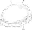
- FIG. 4 is an external perspective view illustrating a state in which a protective sheet is fixed by protective sheet fixing means according to the present embodiment
- 1 is an external perspective view showing a cannula protection assembly according to a first embodiment
- FIG. 1 is a front view of a cannula protection assembly according to a first embodiment
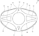
- FIG. Fig. 2 is a plan view of the cannula protection assembly according to the first embodiment
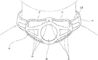
- FIG. 4 is an external view illustrating a state in which the cannula protection assembly according to the first embodiment is attached;
- FIG. 1 is an external perspective view showing a cannula protection assembly according to a first embodiment
- FIG. 1 is a front view of a cannula protection assembly according to a first embodiment
- FIG. Fig. 2 is a plan view of the cannula protection assembly according to the first embodiment
- FIG. 4 is an external view illustrating a
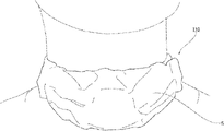
- FIG. 4 is an external view illustrating a state in which the cannula protection assembly according to the first embodiment is covered with a protection sheet
- FIG. 11 is an external perspective view showing a cannula protection assembly according to a second embodiment
- Fig. 10 is a rear view of the cannula protection assembly according to the second embodiment
- Fig. 10 is a plan view of a cannula protection assembly according to a second embodiment
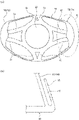
- FIG. 10A is a view illustrating a protective sheet fixing means according to a modification
- FIG. FIG. (b) is a schematic diagram for explaining the A portion of the sub-diagram (a) in the figure. It is a figure which illustrates the protective sheet fixing means which concerns on a modification.
- FIG. 1 is an external perspective view for explaining a configuration example of the cannula protection assembly according to this embodiment.
- FIG. 2 is an external perspective view illustrating a state in which the protective sheet is fixed by the protective sheet fixing means according to this embodiment.
- the direction corresponding to the mounting of the cannula protection assembly 100 will be defined. That is, the side in contact with the patient (incision side, frame 10 side) is defined as “bottom”, the lower side of the paper surface in FIG. The direction opposite to the direction indicated by the arrow) is called “up”.
- a cannula protection assembly (hereinafter also simply referred to as a “cannula protection assembly” or “assembly”) 100 according to the present embodiment is inserted into an incision (not shown) or the incision.
- a cannula protection assembly opening 30 arranged at a position corresponding to the portion (cannula opening) 3; a connecting part 50 consisting of a plurality of arms 51 connecting the frame 10 and the cannula protection assembly opening 30; Prepare.
- the cannula protection assembly 100 is installed to cover the exposed portion of the cannula 1 inserted into an incision (not shown) or an incision.
- the incision may be a tracheostomy or a permanent tracheostomy.
- Cannula protection assembly 100 can also be used in patients with permanent stomas without cannula 1 . In such a case, the cannula protection assembly 100 can be worn on the patient's neck to cover the permanent stoma and prevent airborne viruses and the like from entering the stoma.
- the frame 10 is a base member of the cannula protection assembly 100 that surrounds an externally exposed portion of the cannula 1 inserted into an incision (not shown) or an incision.
- the frame 10 has a curved shape on the opposite side of the incision not shown (counter-incision side) or the side opposite to the direction of inserting the cannula 1 into the incision, that is, the cannula protection assembly opening 30 side.
- a curved portion 11 may be provided. Such curved portions 11 can be paired. This configuration allows cannula protection assembly 100 to fit the body (neck) of the patient to whom assembly 100 is to be worn.
- a cannula protection assembly opening is provided in the upper portion of the cannula protection assembly 100 above the cannula opening 3 (or incision not shown) at a position corresponding to the incision or cannula opening 3.
- a section 30 is arranged.
- the opening diameter of the cannula protection assembly opening 30 is adjusted to the opening of the incision or the cannula opening 3. It can be larger than the caliber.
- the shape of the cannula protection assembly opening 30 is not particularly limited, and may be circular, elliptical, square, or the like.
- the frame 10 and the cannula protection assembly opening 30 are connected by a connecting portion 50 consisting of two arms 51 , 51 .
- the number and arrangement positions of the plurality of arms 51 are not particularly limited as long as they can connect the frame 10 and the cannula protection assembly opening 30 and can impart strength to the cannula protection assembly 100, and can be changed as appropriate.
- the plurality of arms 51 may be equally spaced, for example, may be arranged radially from the cannula protection assembly opening 30 toward the frame 10 .
- the plurality of arms 51 may have a truss, rigid frame, or honeycomb structure to add strength to the cannula protection assembly 100 .
- the connecting part 50 is configured to have a space and may have a plurality of spaces. Such a configuration allows cannula protection assembly 100 to maintain its strength while also ensuring ease of breathing for a patient breathing through an incision or cannula.
- both ends of the frame 10 where the two arms 51, 51 are arranged The maximum diameter between the two arms (see FIG. 1) can be 75 mm or more and 95 mm or less. It can be 45 mm or more and 60 mm or less.
- the height from the patient's skin (incision) to the cannula protection assembly opening 30 can be 30 mm or more and 45 mm or less, and the minimum diameter of the opening of the cannula protection assembly opening 30 can be 25 mm or more and 35 mm or less. can do.
- the inner surface area of the portion surrounded by the frame 10, the connecting portion 50, and the cannula protection assembly opening 30 can be 8,000 mm 2 or more and 12,000 mm 2 or less, and the volume is 100,000 mm 3 . 125,000 mm 3 or less.
- the cannula protection assembly 100 can detachably fix a protection sheet that covers the cannula protection assembly 100 .
- a method of fixing the protective sheet covering the cannula protective assembly 100 for example, the end of the protective sheet covering the cannula protective assembly 100 is wrapped around the frame 10, the end of the protective sheet is passed between the plurality of arms 51, and a plurality of arms 51 are attached.
- the ends of the protective sheet passed between the arms 51 are wrapped around the arms 51, and the ends of the protective sheet passed between the arms 51 are tied together.
- the cannula protection assembly 100 can be provided with protection sheet fixing means for fixing the protection sheet.
- the protective sheet fixing means 70 can be provided as a separate member as a protective sheet holding member 71 for holding the protective sheet S together with the cannula protective assembly 100, for example.
- the protective sheet holding body 71 is configured to hold the protective sheet S together with the cannula protective assembly 100 after covering the cannula protective assembly 100 with the protective sheet S.
- the shape of the protective sheet clamping member 71 is not particularly limited as long as it can clamp the protective sheet S with the cannula protection assembly 100, but the protective sheet clamping member 71 of the present embodiment is configured to have substantially the same shape as the frame 10. can be done. With such a configuration, the protective sheet S can be more securely fixed to the cannula protective assembly 100 .
- the protective sheet holding body 71 is configured to hold the protective sheet S on the side opposite to the patient (incision hole) side of the cannula protection assembly 100. It may be configured such that the protection sheet S is sandwiched on the incision hole side. In this case, the outer diameter of the protective sheet holding member 71 can be made smaller than the inner diameter of the frame 10 . With such a configuration, the protective sheet holding body 71 can fix the protective sheet S on the patient (incision hole) side.
- the protective sheet fixing means 70 is not limited to the protective sheet holding body 71, and may be formed by arranging hook-and-loop fasteners, magnets, or double-sided tape on the frame 10. Moreover, the protective sheet fixing means 70 may be formed by arranging hook-and-loop fasteners, magnets, or double-sided tapes on the frame 10 and the protective sheet holding member 71 . By constructing the protective sheet fixing means 70 with hook-and-loop fasteners, magnets, or double-sided tape, the cannula protective assembly 100 can be manufactured at low cost and easily repaired, so long-term use can be expected.
- the material constituting the cannula protection assembly 100 according to this embodiment is not particularly limited, but it can be an elastic body. Since the material constituting the cannula protection assembly 100 is an elastic body, the cannula protection assembly 100 can obtain the necessary strength and can be light in weight. In addition, the close contact with the patient who wears the cannula protection assembly 100 and the patient's wearing comfort are improved.
- the protective sheet covering the cannula protective assembly 100 is not particularly limited, but can be a non-woven fabric mask.
- a non-woven fabric mask as a protective sheet, it is possible to easily prevent invasion of airborne viruses and the like without imposing a large economic burden and without the need for cutting.
- the protection sheet can be folded and wrapped around the frame 10 or the like, for example, as described above. Since the protective sheet can be fixed by the adhesive, there is an advantage that it does not take time to cut the protective sheet.
- the method for fixing the cannula protection assembly 100 according to this embodiment to the body is not particularly limited, but it may be fixed using a paper tape, provided with through holes in the frame 10 or the plurality of arms 51 as described later, or Using the space formed between the plurality of arms 51, a string or holder can be passed through the through hole or space and fixed.
- a holder a holder that is used as a cannula holder may be used.
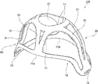
- FIG. 3 is an external perspective view showing the cannula protection assembly according to the first embodiment
- FIG. 4 is a front view showing the cannula protection assembly according to the first embodiment
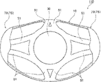
- FIG. 1 is a plan view of a cannula protection assembly according to a first embodiment
- FIG. 6 is an external view illustrating a state in which the cannula protection assembly according to the first embodiment is attached
- FIG. 7 illustrates a state in which the cannula protection assembly according to the first embodiment is covered with a protective sheet. It is an external view.
- the same reference numerals may be assigned to the same or similar configurations as those of the above-described embodiment, and the description thereof may be omitted.
- the direction corresponding to the mounting of the cannula protection assembly 110 will be defined.
- the top side of the patient wearing the cannula protection assembly 110 will be referred to as the "front” or “front” side
- the side of the patient's feet wearing the cannula protection assembly 110 will be referred to as the "back” or “back”. That is, the upper side of FIG. 6 is called “front”, and the lower side of FIG. 6 is called “back”.
- a cannula protection assembly (hereinafter also simply referred to as a "cannula protection assembly” or “assembly”) 110 according to the first embodiment is provided on the opposite side of an incision (unillustrated side) or a cannula (not illustrated).
- a cannula protection assembly opening 30 positioned at the top of the cannula protection assembly 110 and corresponding to an incision or cannula opening (not shown); the frame 10 and the cannula; a connecting part 50 consisting of a plurality of arms 51 connecting with the protection assembly opening 30 .
- the frame 10 has curved portions 11 configured to curve toward the cannula protection assembly opening 30, and such curved portions 11 form pairs. configured as follows. This configuration allows the cannula protection assembly 110 to fit the patient's body (neck).
- the frame 10 according to the first embodiment is constructed with a through-hole 13 through which the holder H for fixing the cannula protection assembly 110 to the neck passes (see FIG. 6). ).
- Such a configuration facilitates securing the cannula protection assembly 110 to the neck, as shown in FIG.
- the cannula (not shown) has a through hole through which the cannula holder passes
- the cannula (not shown) and the cannula protection assembly 110 can be fixed by the cannula holder or the holder H, so that the number of parts can be reduced, the weight can be reduced, and convenience can be achieved.
- the frame 10 according to the first embodiment has a waveform shape (specifically, an elliptical shape) on the front side (parietal region of the patient) in plan view, and is recessed in two places.
- the back side (patient's foot) side has an elliptical shape. That is, the frame 10 according to the first embodiment is configured to have a pair of recessed portions 15, 15 recessed in the axial direction at the center of the cannula protection assembly opening 30 on the top of the patient's head. ing.
- the frame 10 according to the first embodiment has an asymmetric shape in plan view with respect to a line passing through the longitudinal direction of the frame 10 (the center of the cannula protection assembly opening 30 and the through hole 13).
- the maximum diameter of the frame 10 on the front side in the direction perpendicular to the longitudinal direction of the frame 10 is shorter than that on the back side. , that is, the distance from the line passing through the longitudinal direction of the frame 10 is shortened.
- connection part 50 is configured as a total of eight arms 51 that connect two arms from each of the four sides of the frame 10 to the cannula protection assembly opening 30 .
- adjacent arms 51, 51 are integrally formed at the frame 10 portion and are configured to split midway toward the cannula protection assembly opening 30.
- a space having a substantially triangular or trapezoidal shape is formed between the adjacent arms 51, 51, as shown in FIGS. This configuration provides both the necessary strength to the cannula protection assembly 110 and ease of breathing for the patient breathing through the cannula.
- the cannula protection assembly 110 may detachably secure the protective sheet S, such as by wrapping the ends of the protective sheet S around the frame 10, as described above.
- the protective sheet S may be fixed by the protective sheet fixing means 70 exemplified in .
- a portion of the protective sheet S covering the cannula protective assembly 110 may be fixed to the cannula holder or the holder H by fixing means such as hook-and-loop fastener, magnet, double-sided tape, or the like.
- fixing means such as hook-and-loop fastener, magnet, double-sided tape, or the like.
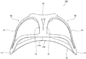
- FIG. 8 is an external perspective view showing the cannula protection assembly according to the second embodiment
- FIG. 9 is a rear view showing the cannula protection assembly according to the second embodiment
- Figure 10 is a plan view of a cannula protection assembly according to a second embodiment
- a cannula protection assembly 120 (hereinafter also referred to simply as a “cannula protection assembly” or “assembly”) 120 according to the second embodiment is provided on the opposite side of an incision (not shown) or a cannula (not shown).
- a connecting portion 50 consisting of a plurality of arms 51 that connect with the assembly opening 30 .
- the frame 10 according to the second embodiment has a curved portion 11 curved toward the cannula protection assembly opening 30, and such curved portions 11 (11A, 11B ) are constructed in pairs.
- One curved portion 11A of the frame 10 according to the second embodiment that is, the curved portion 11A on the back side (the patient's leg side) is configured to have an inverted U shape recessed toward the cannula protection assembly opening 30 side.
- the other curved portion 11B of the frame 10 according to the second embodiment that is, the curved portion 11B on the front side (parietal side of the patient) has an arcuate shape recessed in an elliptical shape toward the cannula protection assembly opening 30 side. It is configured.
- the cannula protection assembly 120 according to the second embodiment when the cannula protection assembly 120 according to the second embodiment is attached to a patient who has an enlarged permanent tracheostomy, the patient's neck and chest (unevenness caused by the clavicle) are adapted to fit. .
- the frame 10 according to the second embodiment has a waveform (specifically, an elliptical shape) on the front side (that is, the patient's parietal side) in plan view, as in the above-described embodiments.
- the shape has concave portions 15, 15 that are recessed inward at two locations).
- the frame 10 according to the second embodiment is configured to have a substantially omega shape in which the rear side (that is, the patient's foot side) is recessed toward the front side in the vicinity of the through hole 13 in plan view.
- the cannula protection assembly 120 according to the second embodiment when the cannula protection assembly 120 according to the second embodiment is attached to a patient who has an enlarged permanent tracheostomy, the patient's neck and chest (unevenness caused by the clavicle) are adapted to fit. .
- the cannula protection assembly 120 according to the second example may include the protective sheet fixing means 70 according to the embodiment described above.
- the protective sheet fixing means 70 is configured to have the protective sheet holding body 71, but as shown in FIG. There may also be a frame protrusion 73 which has a clearance C for inserting a second protective sheet and protrudes from the frame 10 toward the cannula protection assembly opening 30 .
- the frame protruding portion 73 is configured so that the vicinity of the connecting portion 50 (arm portion) is higher than the other portions, although this is not a particular limitation. With such a configuration, the protective sheet (not shown) can be fixed more reliably.
- the protective sheet fixing means 70 may be configured by combining the protective sheet fixing means 70 described above.
- the protective sheet fixing means 70 may be, for example, a clip 75 having the same shape as the frame projecting portion 73 when viewed from the front.
- a protective sheet (not shown) may be attached to the cannula protective assembly 110 described above, and clips 75, 75 may be attached to both ends of the frame 10 to secure the protective sheet (not shown).
- the above-described embodiments are configured with through holes 13 through which holders for securing the cannula protection assemblies 110, 120 to the neck are provided, the adjacent arms 51, 51 of the cannula protection assemblies 110, 120 are removed.
- the holder may be passed through the space formed between and the through hole 13 may not be provided.
- 100, 110, 120 cannula protection assembly; 1: cannula, 3: cannula opening, 10: frame, 11: curved portion, 13: through hole, 15: concave portion, 30: cannula protection assembly opening, 50: connecting part, 51: arm, 70: protective sheet fixing means, 71: protective sheet clamping body, 73: frame protrusion, 75: clip C: gap, H: holder, S: protective sheet
Landscapes
- Health & Medical Sciences (AREA)
- Pulmonology (AREA)
- Emergency Medicine (AREA)
- Engineering & Computer Science (AREA)
- Anesthesiology (AREA)
- Biomedical Technology (AREA)
- Heart & Thoracic Surgery (AREA)
- Hematology (AREA)
- Life Sciences & Earth Sciences (AREA)
- Animal Behavior & Ethology (AREA)
- General Health & Medical Sciences (AREA)
- Public Health (AREA)
- Veterinary Medicine (AREA)
- Surgical Instruments (AREA)
Abstract
切開孔又は該切開孔に挿入されるカニューレの体外に露出した開口部を保護するためのカニューレ保護アッセンブリであって、前記切開孔又は体外に露出したカニューレを囲むフレームと、前記切開孔又は体外に露出したカニューレの開口部と対応する位置に配置されるカニューレ保護アッセンブリ開口部と、前記フレームと前記カニューレ保護アッセンブリ開口部とを連結する、複数のアームからなる連結部と、を備える、カニューレ保護アッセンブリ。
Description
本発明は、カニューレ保護アッセンブリに関する。
切開孔や切開孔に挿入されるカニューレの体外に露出した開口部への異物の混入等を防ぐ必要がある。また、患者に永久気管孔を作製した場合にも同様に開口部(切開孔)への異物の混入を防ぐ必要がある。
例えば、特許文献1には、柔軟且つ半硬質の素材を円筒又はその他の筒形状にし、内外側は平面又は波状又はその他の形状を有したものにし、外側の周囲に数本の溝を設けてガーゼを被せ、輪ゴムを食込ませて固定させるとともに、下部底面は、平坦又は喉に合わせて曲線状に形成させ、ゴム紐又は柔軟バンドを首に回し気管カニユーレマスクに設けた穴に通し、カニユーレに触れることなくカニユーレ全体を包んで装着すべくようにしたことを特徴とした分離式気管カニユーレマスクが開示され、家族でもガーゼ交換ができると記載されている。
しかしながら、特許文献1に記載された発明では、ガーゼを特定の大きさに切断する手間がかかり、また、体外に露出したカニューレの開口部をガーゼにより保護しているため、空気中に浮遊する極微細な物質、例えばウイルスや細菌の侵入を十分に防ぐことができないという課題があった。
空気中に浮遊するウイルスや細菌の侵入を防ぐために、特許文献1に記載された発明のガーゼを高いフィルター機能を有する素材のものに替える必要があるが、ガーゼと同様に輪ゴムにより簡単かつ十分に固定できるとともに高いフィルター機能を有する素材を入手することが困難であるという課題があった。また、特許文献1に記載された発明においては、通気機能を有する通気部が、ガーゼで覆われる円筒又は筒形状の開口部のみであるので、カニューレを通して呼吸をしている患者は、呼吸をしづらくなってしまうという課題があった。
本発明が解決しようとする課題は、簡便な作業で空気中に浮遊するウイルス等の侵入を防ぐことができるカニューレ保護アッセンブリを提供することにある。
本発明者は、以下の構成を採用することにより上記課題を解決できることを見出し、発明を完成させるに至った。
すなわち、本発明は、以下のとおりである。
<1> 切開孔又は該切開孔に挿入されるカニューレの体外に露出した開口部を保護するためのカニューレ保護アッセンブリであって、前記切開孔又は体外に露出したカニューレを囲むフレームと、前記切開孔又は体外に露出したカニューレの開口部と対応する位置に配置されるカニューレ保護アッセンブリ開口部と、前記フレームと前記カニューレ保護アッセンブリ開口部とを連結する、複数のアームからなる連結部と、を備える、カニューレ保護アッセンブリ。
<2> 前記フレームが、前記カニューレ保護アッセンブリ開口部側に湾曲する湾曲部を備える、上記<1>に記載のカニューレ保護アッセンブリ。
<3> 前記カニューレ保護アッセンブリ開口部が、前記切開孔又はカニューレの開口部の開口径よりも大きい開口径を有する、上記<1>又は<2>に記載のカニューレ保護アッセンブリ。
<4> 前記フレーム又は前記連結部に、カニューレ保護アッセンブリを頸部に固定するためのホルダーを通す貫通孔を備える、上記<1>~<3>のいずれか1つに記載のカニューレ保護アッセンブリ。
<5> 前記複数のアームが、前記カニューレ保護アッセンブリ開口部から前記フレームに向かって放射状に配置される、上記<1>~<4>のいずれか1つに記載のカニューレ保護アッセンブリ。
<6> カニューレ保護アッセンブリを覆う保護シートを着脱自在に固定可能である、上記<1>~<5>のいずれか1つに記載のカニューレ保護アッセンブリ。
<7> カニューレ保護アッセンブリを覆う保護シートを固定する保護シート固定手段をさらに備える、上記<1>~<6>のいずれか1つに記載のカニューレ保護アッセンブリ。
<8> 前記保護シート固定手段が、前記保護シートを挟持する保護シート挟持体を備える、上記<7>に記載のカニューレ保護アッセンブリ。
<9> 前記保護シート固定手段が、前記連結部との間に保護シートを挿入する隙間を有し、かつ、前記フレームから前記カニューレ保護アッセンブリ開口部に向かって突出するフレーム突出部を備える、上記<7>又は<8>に記載のカニューレ保護アッセンブリ。
<10> 前記保護シート固定手段が、面ファスナを備える、上記<7>~<9>のいずれか1つに記載のカニューレ保護アッセンブリ。
<11> 前記保護シート固定手段が、磁石を備える、上記<7>~<10>のいずれか1つに記載のカニューレ保護アッセンブリ。
<12> 前記保護シートが、不織布マスクである、上記<6>~<11>のいずれか1つに記載のカニューレ保護アッセンブリ。
<13> カニューレ保護アッセンブリを構成する素材が弾性体である、上記<1>~<12>のいずれか1つに記載のカニューレ保護アッセンブリ。
<1> 切開孔又は該切開孔に挿入されるカニューレの体外に露出した開口部を保護するためのカニューレ保護アッセンブリであって、前記切開孔又は体外に露出したカニューレを囲むフレームと、前記切開孔又は体外に露出したカニューレの開口部と対応する位置に配置されるカニューレ保護アッセンブリ開口部と、前記フレームと前記カニューレ保護アッセンブリ開口部とを連結する、複数のアームからなる連結部と、を備える、カニューレ保護アッセンブリ。
<2> 前記フレームが、前記カニューレ保護アッセンブリ開口部側に湾曲する湾曲部を備える、上記<1>に記載のカニューレ保護アッセンブリ。
<3> 前記カニューレ保護アッセンブリ開口部が、前記切開孔又はカニューレの開口部の開口径よりも大きい開口径を有する、上記<1>又は<2>に記載のカニューレ保護アッセンブリ。
<4> 前記フレーム又は前記連結部に、カニューレ保護アッセンブリを頸部に固定するためのホルダーを通す貫通孔を備える、上記<1>~<3>のいずれか1つに記載のカニューレ保護アッセンブリ。
<5> 前記複数のアームが、前記カニューレ保護アッセンブリ開口部から前記フレームに向かって放射状に配置される、上記<1>~<4>のいずれか1つに記載のカニューレ保護アッセンブリ。
<6> カニューレ保護アッセンブリを覆う保護シートを着脱自在に固定可能である、上記<1>~<5>のいずれか1つに記載のカニューレ保護アッセンブリ。
<7> カニューレ保護アッセンブリを覆う保護シートを固定する保護シート固定手段をさらに備える、上記<1>~<6>のいずれか1つに記載のカニューレ保護アッセンブリ。
<8> 前記保護シート固定手段が、前記保護シートを挟持する保護シート挟持体を備える、上記<7>に記載のカニューレ保護アッセンブリ。
<9> 前記保護シート固定手段が、前記連結部との間に保護シートを挿入する隙間を有し、かつ、前記フレームから前記カニューレ保護アッセンブリ開口部に向かって突出するフレーム突出部を備える、上記<7>又は<8>に記載のカニューレ保護アッセンブリ。
<10> 前記保護シート固定手段が、面ファスナを備える、上記<7>~<9>のいずれか1つに記載のカニューレ保護アッセンブリ。
<11> 前記保護シート固定手段が、磁石を備える、上記<7>~<10>のいずれか1つに記載のカニューレ保護アッセンブリ。
<12> 前記保護シートが、不織布マスクである、上記<6>~<11>のいずれか1つに記載のカニューレ保護アッセンブリ。
<13> カニューレ保護アッセンブリを構成する素材が弾性体である、上記<1>~<12>のいずれか1つに記載のカニューレ保護アッセンブリ。
本発明によれば、簡便な作業で空気中に浮遊するウイルス等の侵入を防ぐことができるカニューレ保護アッセンブリを提供できる。
以下、本発明を実施するための好適な実施形態について、図面を用いて説明する。なお、以下の実施形態は、各請求項に係る発明を限定するものではなく、また、実施形態の中で説明されている特徴の組み合わせの全てが発明の解決手段に必須であるものではない。
まず、本実施形態に係るカニューレ保護アッセンブリ100の構成について、図1及び図2を用いて説明する。ここで、図1は、本実施形態に係るカニューレ保護アッセンブリの構成例を説明するための外観斜視図である。図2は、本実施形態に係る保護シート固定手段により保護シートを固定した状態を例示する外観斜視図である。
なお、以下の説明では、説明の便宜のためにカニューレ保護アッセンブリ100の装着時に応じた方向を定義することとする。すなわち、患者に接する側(切開孔側、フレーム10側)を「下」とし、図1における紙面下側(図1における矢印が示す方向)を「下」、図1における紙面上側(図1における矢印が示す方向とは反対の方向)を「上」と呼ぶこととする。
[カニューレ保護アッセンブリ100]
図1及び図2に示すように、本実施形態に係るカニューレ保護アッセンブリ(以下、単に「カニューレ保護アッセンブリ」又は「アッセンブリ」ともいう)100は、不図示の切開孔又は該切開孔に挿入されるカニューレ1の体外に露出した開口部3を保護するためのカニューレ保護アッセンブリ100であって、前記切開孔又は体外に露出したカニューレ1を囲むフレーム10と、前記切開孔又は体外に露出したカニューレの開口部(カニューレ開口部)3と対応する位置に配置されるカニューレ保護アッセンブリ開口部30と、前記フレーム10と前記カニューレ保護アッセンブリ開口部30とを連結する、複数のアーム51からなる連結部50と、を備える。
図1及び図2に示すように、本実施形態に係るカニューレ保護アッセンブリ(以下、単に「カニューレ保護アッセンブリ」又は「アッセンブリ」ともいう)100は、不図示の切開孔又は該切開孔に挿入されるカニューレ1の体外に露出した開口部3を保護するためのカニューレ保護アッセンブリ100であって、前記切開孔又は体外に露出したカニューレ1を囲むフレーム10と、前記切開孔又は体外に露出したカニューレの開口部(カニューレ開口部)3と対応する位置に配置されるカニューレ保護アッセンブリ開口部30と、前記フレーム10と前記カニューレ保護アッセンブリ開口部30とを連結する、複数のアーム51からなる連結部50と、を備える。
図1の矢印にて示すように、カニューレ保護アッセンブリ100は、不図示の切開孔又は切開孔に挿入されるカニューレ1の体外に露出する部分を覆うように設置されるものである。切開孔は、気管切開孔や永久気管孔であってもよい。カニューレ保護アッセンブリ100は、カニューレ1を装着していない永久気管孔を有する患者においても使用可能である。かかる場合、カニューレ保護アッセンブリ100は、永久気管孔を覆うように患者の頸部に装着され、空気中に浮遊するウイルス等の永久気管孔への侵入を防ぐことができる。
フレーム10は、不図示の切開孔又は切開孔に挿入されるカニューレ1の体外に露出する部分を囲む、カニューレ保護アッセンブリ100のベースとなる部材である。フレーム10は、不図示の切開孔の反対側(反切開孔側)又はカニューレ1を切開孔内に挿入する方向とは反対側、すなわち、カニューレ保護アッセンブリ開口部30側に、湾曲した形状を有する湾曲部11を備えることとすることができる。かかる湾曲部11は対をなすこととすることができる。このような構成により、カニューレ保護アッセンブリ100が、アッセンブリ100を装着する患者の体(頸部)にフィットするようになっている。
図1に示すように、カニューレ保護アッセンブリ100の上部には、カニューレ開口部3(又は不図示の切開孔)の上方であって、切開孔又はカニューレ開口部3と対応する位置にカニューレ保護アッセンブリ開口部30が配置される。このような構成により、カニューレ保護アッセンブリ100を患者が装着したままでも、不図示の保護シートを取り外せばカニューレ1の操作、切開孔周辺に付着した痰の除去や切開孔の消毒等の処置ができる。切開孔、カニューレ開口部3及びカニューレ保護アッセンブリ開口部30は、同軸中心とすることができる。カニューレ保護アッセンブリ100を装着した状態から迅速かつ容易にカニューレ1の操作や切開孔の処置を行えるようにする観点から、カニューレ保護アッセンブリ開口部30の開口径を、切開孔又はカニューレ開口部3の開口径よりも大きくすることができる。なお、カニューレ保護アッセンブリ開口部30の形状は、特に限定されず、円形状、楕円形状、四角形状等にすることができる。
本実施形態に係るカニューレ保護アッセンブリ100は、フレーム10とカニューレ保護アッセンブリ開口部30とが、2本のアーム51,51からなる連結部50により連結されている。複数のアーム51の数や配置位置は、フレーム10とカニューレ保護アッセンブリ開口部30とを連結し、かつ、カニューレ保護アッセンブリ100に強度を付与できれば特に限定されず、適宜変更することができる。複数のアーム51は、等間隔で配置することができ、例えば、カニューレ保護アッセンブリ開口部30からフレーム10に向かって放射状に複数配置してもよい。また、複数のアーム51は、カニューレ保護アッセンブリ100に強度を付与するために、トラス構造、ラーメン構造、又はハニカム構造を有していてもよい。なお、連結部50の面積が大きすぎると、切開孔又はカニューレを通して呼吸をしている患者は、呼吸をしづらくなってしまうため、連結部50は、複数のアーム51同士の間に、適度に空間を有するように構成され、複数の空間を有することとすることができる。このような構成により、カニューレ保護アッセンブリ100は、その強度を保持しつつ、切開孔又はカニューレを通して呼吸をしている患者の呼吸のしやすさも確保することができる。
なお、特に限定されないが、本実施形態に係るカニューレ保護アッセンブリ100を、気管切開術後にカニューレを装着している患者に使用する場合、2本のアーム51,51が配置されるフレーム10両端の間の最大径(図1参照)は、75mm以上95mm以下とすることができ、2本のアーム51,51が配置されるフレーム10の両端の間の最大径と直交する方向における最大径は、45mm以上60mm以下とすることができる。また、患者の皮膚(切開孔)からカニューレ保護アッセンブリ開口部30までの高さは、30mm以上45mm以下とすることができ、カニューレ保護アッセンブリ開口部30の開口の最小径は、25mm以上35mm以下とすることができる。さらに、フレーム10と連結部50とカニューレ保護アッセンブリ開口部30とで囲まれた部分の内部の表面積は、8,000mm2以上12,000mm2以下とすることができ、体積は、100,000mm3以上125,000mm3以下とすることができる。
本実施形態に係るカニューレ保護アッセンブリ100は、カニューレ保護アッセンブリ100を覆う保護シートを着脱自在に固定可能である。カニューレ保護アッセンブリ100を覆う保護シートの固定方法としては、例えば、カニューレ保護アッセンブリ100を覆う保護シートの端部をフレーム10に巻き付けたり、保護シートの端部を複数のアーム51の間に通し、複数のアーム51の間に通された保護シートの端部を複数のアーム51に巻き付けたり、複数のアーム51の間に通された保護シートの端部同士を結んだりする方法などが挙げられる。
また、本実施形態に係るカニューレ保護アッセンブリ100は、保護シートを固定する保護シート固定手段を備えることとすることができる。図2に示すように、保護シート固定手段70は、例えば、カニューレ保護アッセンブリ100とで保護シートSを挟持する保護シート挟持体71として別部材とすることができる。保護シート挟持体71は、カニューレ保護アッセンブリ100を保護シートSで覆った後に、カニューレ保護アッセンブリ100とで保護シートSを挟持するように構成される。保護シート挟持体71の形状は、カニューレ保護アッセンブリ100とで保護シートSを挟持できれば特に限定されないが、本実施形態の保護シート挟持体71は、フレーム10と略同一形状を有するように構成することができる。このような構成により、カニューレ保護アッセンブリ100に保護シートSをより確実に固定できる。
本実施形態に係る保護シート挟持体71は、カニューレ保護アッセンブリ100の患者(切開孔)側とは反対側において、保護シートSを挟持するように構成されているが、カニューレ保護アッセンブリ100の患者(切開孔)側で保護シートSを挟持するように構成されてもよい。この場合、保護シート挟持体71の外径は、フレーム10の内径よりも小さくすることができる。このような構成により、保護シート挟持体71は、保護シートSを患者(切開孔)側で固定することができる。
保護シート固定手段70は、保護シート挟持体71に限定されず、フレーム10に面ファスナ、磁石、又は両面テープを配置することにより形成してもよい。また、保護シート固定手段70は、フレーム10及び保護シート挟持体71に面ファスナ、磁石、又は両面テープを配置することにより形成してもよい。保護シート固定手段70が、面ファスナ、磁石、又は両面テープを有して構成されることにより、カニューレ保護アッセンブリ100を安価に製造でき、修理も容易であるため、長期間の使用を望める。
本実施形態に係るカニューレ保護アッセンブリ100を構成する素材は、特に限定されないが、弾性体とすることができる。カニューレ保護アッセンブリ100を構成する素材が弾性体であることにより、カニューレ保護アッセンブリ100に必要な強度を得ると同時に、軽量化できる。また、カニューレ保護アッセンブリ100を装着する患者との密着性や患者の装着感が向上する。
カニューレ保護アッセンブリ100を覆う保護シートは、特に限定されないが、不織布マスクとすることができる。保護シートとして不織布マスクを用いることにより、大きな経済的負担をかけることなく、切断する手間もないので簡便に、空気中に浮遊するウイルス等の侵入を防ぐことができる。
本実施形態に係るカニューレ保護アッセンブリ100は、保護シートの大きさがカニューレ保護アッセンブリ100の大きさよりも大きくても、保護シートを折り曲げて、例えば、上述したように、フレーム10等に巻き付けたりすることにより固定することができるため、保護シートを切断する手間がかからないという利点を有する。
本実施形態に係るカニューレ保護アッセンブリ100を身体に固定する方法としては、特に限定されないが、紙テープを用いて固定したり、後述するように、フレーム10又は複数のアーム51に貫通孔を設けたり、複数のアーム51同士の間に形成される空間を利用して、紐やホルダーを貫通孔又は空間に通して固定することができる。ホルダーとしては、カニューレホルダーとして使用されているホルダーを使用してもよい。
以上、本実施形態に係るカニューレ保護アッセンブリ100の構成例について説明した。次に、第一の実施例に係るカニューレ保護アッセンブリ110について、図3乃至図7を用いて説明する。ここで、図3は、第一の実施例に係るカニューレ保護アッセンブリを示す外観斜視図であり、図4は、第一の実施例に係るカニューレ保護アッセンブリを示す正面図であり、また、図5は、第一の実施例に係るカニューレ保護アッセンブリを示す平面図である。図6は、第一の実施例に係るカニューレ保護アッセンブリを装着した状態を例示する外観図であり、図7は、第一の実施例に係るカニューレ保護アッセンブリを保護シートで覆った状態を例示する外観図である。なお、上述した実施形態と同一又は類似する構成については、同一の符号を付して説明を省略する場合がある。
なお、以下の説明では、説明の便宜のためにカニューレ保護アッセンブリ110の装着時に応じた方向を定義することとする。カニューレ保護アッセンブリ110を装着された患者の頭頂部側を「正面」又は「前」、カニューレ保護アッセンブリ110を装着された患者の足側を「背面」又は「後」と呼ぶこととする。すなわち、図6における紙面上側を「正面」、図6における紙面下側を「背面」と呼ぶこととする。
[第一の実施例に係るカニューレ保護アッセンブリ110]
第一の実施例に係るカニューレ保護アッセンブリ(以下、単に「カニューレ保護アッセンブリ」又は「アッセンブリ」ともいう)110は、不図示の切開孔の反対側(反切開孔側)又は不図示のカニューレを切開孔内に挿入する方向の反対側に配置されるカニューレ開口部(不図示)を保護するためのカニューレ保護アッセンブリ110であって、不図示の切開孔又は該切開孔に挿入されるカニューレ1の体外に露出した部分を囲むフレーム10と、カニューレ保護アッセンブリ110の上部であって、切開孔又はカニューレ開口部(不図示)と対応する位置に配置されるカニューレ保護アッセンブリ開口部30と、フレーム10とカニューレ保護アッセンブリ開口部30とを連結する、複数のアーム51からなる連結部50と、を備えて構成される。
第一の実施例に係るカニューレ保護アッセンブリ(以下、単に「カニューレ保護アッセンブリ」又は「アッセンブリ」ともいう)110は、不図示の切開孔の反対側(反切開孔側)又は不図示のカニューレを切開孔内に挿入する方向の反対側に配置されるカニューレ開口部(不図示)を保護するためのカニューレ保護アッセンブリ110であって、不図示の切開孔又は該切開孔に挿入されるカニューレ1の体外に露出した部分を囲むフレーム10と、カニューレ保護アッセンブリ110の上部であって、切開孔又はカニューレ開口部(不図示)と対応する位置に配置されるカニューレ保護アッセンブリ開口部30と、フレーム10とカニューレ保護アッセンブリ開口部30とを連結する、複数のアーム51からなる連結部50と、を備えて構成される。
図3及び図4に示すように、第一の実施例に係るフレーム10は、カニューレ保護アッセンブリ開口部30側に湾曲して構成される湾曲部11を有し、かかる湾曲部11は対をなして構成されている。このような構成により、カニューレ保護アッセンブリ110が患者の体(頸部)にフィットするようになっている。
図3及び図4に示すように、第一の実施例に係るフレーム10は、カニューレ保護アッセンブリ110を頸部に固定するためのホルダーHを通す貫通孔13を備えて構成される(図6参照)。このような構成により、図6に示すように、カニューレ保護アッセンブリ110を容易に頸部に固定できるようになっている。また、不図示のカニューレがカニューレホルダーを通す貫通孔を有する場合、カニューレホルダー又はホルダーHにより不図示のカニューレ及びカニューレ保護アッセンブリ110を固定できるため、部品数が減り、軽量化が図れるとともに、利便性に優れる。
図5及び図6に示すように、第一の実施例に係るフレーム10は、平面視において、正面(患者の頭頂部)側が波形形状(具体的には楕円形状を内側に2ヵ所窪ませた凹形状部15,15を有する形状)を有し、背面(患者の足)側が楕円形状を有して構成されている。すなわち、第一の実施例に係るフレーム10は、患者の頭頂部側に、カニューレ保護アッセンブリ開口部30の中心の軸方向に向かって窪む一対の凹形状部15,15を有して構成されている。第一の実施例に係るフレーム10は、平面視において、フレーム10の長手方向(カニューレ保護アッセンブリ開口部30及び貫通孔13の中心)を通る線に対して、非対称な形状を有している。より詳しくは、第一の実施例に係るフレーム10は、背面側のフレーム10よりも正面側のフレーム10の方が、フレーム10の長手方向と垂直の方向(前後方向)の最大径が短くなるように、すなわちフレーム10の長手方向を通る線からの距離が短くなるように構成されている。このような構成により、カニューレ保護アッセンブリ110を、気管切開術後の患者に装着する際に、患者の頸部にフィットするとともに、患者の下顎とカニューレ保護アッセンブリ110との干渉を最小限にできるようになっている。
図5に示すように、第一の実施例に係る連結部50は、フレーム10の四方から2本ずつカニューレ保護アッセンブリ開口部30と連結する、合計8本のアーム51として構成されている。図3に示すように、隣接するアーム51,51は、フレーム10部分では一体形成されており、カニューレ保護アッセンブリ開口部30に向かって途中から2本に分かれるように構成されている。そして、隣接するアーム51,51の間には、図3及び図5に示すように、略三角形状又は台形状を有する空間が形成されている。このような構成により、カニューレ保護アッセンブリ110に必要な強度の付与と、カニューレを通して呼吸をしている患者の呼吸のしやすさとを両立できるようになっている。
第一の実施例に係るカニューレ保護アッセンブリ110は、上述したように、保護シートSの端部をフレーム10に巻き付ける方法などにより、保護シートSを着脱自在に固定してもよく、上述した実施形態に係る保護シート固定手段70として例示したものにより保護シートSを固定してもよい。また、面ファスナ、磁石、両面テープ等の固定手段により、カニューレ保護アッセンブリ110を覆う保護シートSの一部を、カニューレホルダーやホルダーHに固定してもよい。図7に示すように、カニューレ保護アッセンブリ110を保護シートSで覆って保護シート固定手段70により固定すると、空気中に浮遊するウイルス等が体内に侵入を防ぐことができる。
以上、第一の実施例に係るカニューレ保護アッセンブリ110について説明した。次に、第二の実施例に係るカニューレ保護アッセンブリ120について、図8乃至図10を用いて説明する。ここで、図8は、第二の実施例に係るカニューレ保護アッセンブリを示す外観斜視図であり、図9は、第二の実施例に係るカニューレ保護アッセンブリを示す背面図であり、また、図10は、第二の実施例に係るカニューレ保護アッセンブリを示す平面図である。なお、上述した実施形態と同一又は類似する構成については、同一の符号を付して説明を省略する場合がある。
[第二の実施例に係るカニューレ保護アッセンブリ120]
第二の実施例に係るカニューレ保護アッセンブリ(以下、単に「カニューレ保護アッセンブリ」又は「アッセンブリ」ともいう)120は、不図示の切開孔の反対側(反切開孔側)又は不図示のカニューレを切開孔内に挿入する方向の反対側に配置されるカニューレ開口部(不図示)を保護するためのカニューレ保護アッセンブリ120であって、切開孔又は切開孔に挿入されるカニューレの体外に露出した部分を囲むフレーム10と、カニューレ保護アッセンブリ120の上部であって、切開孔(不図示)又はカニューレ開口部(不図示)と対応する位置に配置されるカニューレ保護アッセンブリ開口部30と、フレーム10とカニューレ保護アッセンブリ開口部30とを連結する、複数のアーム51からなる連結部50と、を備える。
第二の実施例に係るカニューレ保護アッセンブリ(以下、単に「カニューレ保護アッセンブリ」又は「アッセンブリ」ともいう)120は、不図示の切開孔の反対側(反切開孔側)又は不図示のカニューレを切開孔内に挿入する方向の反対側に配置されるカニューレ開口部(不図示)を保護するためのカニューレ保護アッセンブリ120であって、切開孔又は切開孔に挿入されるカニューレの体外に露出した部分を囲むフレーム10と、カニューレ保護アッセンブリ120の上部であって、切開孔(不図示)又はカニューレ開口部(不図示)と対応する位置に配置されるカニューレ保護アッセンブリ開口部30と、フレーム10とカニューレ保護アッセンブリ開口部30とを連結する、複数のアーム51からなる連結部50と、を備える。
図8及び図9に示すように、第二の実施例に係るフレーム10は、カニューレ保護アッセンブリ開口部30側に湾曲して構成される湾曲部11を有し、かかる湾曲部11(11A,11B)は対をなして構成されている。第二の実施例に係るフレーム10の一方の、すなわち背面側(患者の足側)の湾曲部11Aは、カニューレ保護アッセンブリ開口部30側に窪んだ逆U字形状を有して構成されている。また、第二の実施例に係るフレーム10の他方の、すなわち正面側(患者の頭頂部側)の湾曲部11Bは、カニューレ保護アッセンブリ開口部30側に楕円形状に窪んだ円弧形状を有して構成されている。このような構成により、第二の実施例に係るカニューレ保護アッセンブリ120を、永久気管孔を増設した患者に装着する場合、患者の頸部及び胸部(鎖骨による凹凸)にフィットするようになっている。
図10に示すように、第二の実施例に係るフレーム10は、上述した実施例と同様に、平面視において、正面側(すなわち、患者の頭頂部側)が波形形状(具体的には楕円形状を内側に2ヵ所窪ませた凹形状部15,15を有する形状)を有して構成されている。第二の実施例に係るフレーム10は、平面視において、背面側(すなわち、患者の足側)が、貫通孔13近傍では正面側に窪んだ略Ω形状を有して構成されている。このような構成により、第二の実施例に係るカニューレ保護アッセンブリ120を、永久気管孔を増設した患者に装着する場合、患者の頸部及び胸部(鎖骨による凹凸)にフィットするようになっている。
第二の実施例に係るカニューレ保護アッセンブリ120は、上述した実施形態に係る保護シート固定手段70として例示したものを備えていてもよい。
以上、本発明の好適な実施形態について説明したが、本発明の技術的範囲は上記実施形態に記載された範囲には限定されない。上記実施形態には、多様な変更又は改良を加えることが可能である。
例えば、上述した実施形態では、保護シート固定手段70は、保護シート挟持体71を有して構成されているが、図11に示すように、連結部50(アーム51)との間に不図示の保護シートを挿入する隙間Cを有し、かつ、フレーム10からカニューレ保護アッセンブリ開口部30に向かって突出するフレーム突出部73を備えるものであってもよい。フレーム突出部73は、特に限定されないが、連結部50(アーム部)近傍がその他の部分よりも高くなるように構成されている。このような構成により、不図示の保護シートをより確実に固定できるようになっている。また、保護シート固定手段70は、上述した保護シート固定手段70を組み合わせて構成してもよい。
また、保護シート固定手段70は、図12に示すように、例えば、正面視において、上記フレーム突出部73と同様の形状を有するクリップ75であってもよい。不図示の保護シートを、上述したカニューレ保護アッセンブリ110に装着し、フレーム10の両端にクリップ75,75を取付けることにより、不図示の保護シートを固定することとしてもよい。
さらに、上述した実施形態では、カニューレ保護アッセンブリ110,120を頸部に固定するためのホルダーを通す貫通孔13を備えて構成されているが、カニューレ保護アッセンブリ110,120の隣接するアーム51,51の間に形成される空間内にホルダーを通し、貫通孔13を備えていなくてもよい。
100,110,120:カニューレ保護アッセンブリ、
1:カニューレ、3:カニューレ開口部、
10:フレーム、11:湾曲部、13:貫通孔、15:凹形状部
30:カニューレ保護アッセンブリ開口部、
50:連結部、51:アーム、
70:保護シート固定手段、71:保護シート挟持体、73:フレーム突出部、75:クリップ
C:隙間、H:ホルダー、S:保護シート
1:カニューレ、3:カニューレ開口部、
10:フレーム、11:湾曲部、13:貫通孔、15:凹形状部
30:カニューレ保護アッセンブリ開口部、
50:連結部、51:アーム、
70:保護シート固定手段、71:保護シート挟持体、73:フレーム突出部、75:クリップ
C:隙間、H:ホルダー、S:保護シート
Claims (13)
- 切開孔又は該切開孔に挿入されるカニューレの体外に露出した開口部を保護するためのカニューレ保護アッセンブリであって、
前記切開孔又は体外に露出したカニューレを囲むフレームと、
前記切開孔又は体外に露出したカニューレの開口部と対応する位置に配置されるカニューレ保護アッセンブリ開口部と、
前記フレームと前記カニューレ保護アッセンブリ開口部とを連結する、複数のアームからなる連結部と、
を備える、カニューレ保護アッセンブリ。 - 前記フレームが、前記カニューレ保護アッセンブリ開口部側に湾曲する湾曲部を備える、請求項1に記載のカニューレ保護アッセンブリ。
- 前記カニューレ保護アッセンブリ開口部が、前記切開孔又はカニューレの開口部の開口径よりも大きい開口径を有する、請求項1又は2に記載のカニューレ保護アッセンブリ。
- 前記フレーム又は前記連結部に、カニューレ保護アッセンブリを頸部に固定するためのカニューレホルダーを通す貫通孔を備える、請求項1~3のいずれか1項に記載のカニューレ保護アッセンブリ。
- 前記複数のアームが、前記カニューレ保護アッセンブリ開口部から前記フレームに向かって放射状に配置される、請求項1~4のいずれか1項に記載のカニューレ保護アッセンブリ。
- カニューレ保護アッセンブリを覆う保護シートを着脱自在に固定可能である、請求項1~5のいずれか1項に記載のカニューレ保護アッセンブリ。
- カニューレ保護アッセンブリを覆う保護シートを固定する保護シート固定手段をさらに備える、請求項1~6のいずれか1項に記載のカニューレ保護アッセンブリ。
- 前記保護シート固定手段が、前記保護シートを挟持する保護シート挟持体を備える、請求項7に記載のカニューレ保護アッセンブリ。
- 前記保護シート固定手段が、前記連結部との間に保護シートを挿入する隙間を有し、かつ、前記フレームから前記カニューレ保護アッセンブリ開口部に向かって突出するフレーム突出部を備える、請求項7又は8に記載のカニューレ保護アッセンブリ。
- 前記保護シート固定手段が、面ファスナを備える、請求項7~9のいずれか1項に記載のカニューレ保護アッセンブリ。
- 前記保護シート固定手段が、磁石を備える、請求項7~10のいずれか1項に記載のカニューレ保護アッセンブリ。
- 前記保護シートが、不織布マスクである、請求項6~11のいずれか1項に記載のカニューレ保護アッセンブリ。
- カニューレ保護アッセンブリを構成する素材が弾性体である、請求項1~12のいずれか1項に記載のカニューレ保護アッセンブリ。
Applications Claiming Priority (2)
| Application Number | Priority Date | Filing Date | Title |
|---|---|---|---|
| JP2021-116585 | 2021-07-14 | ||
| JP2021116585A JP2023012860A (ja) | 2021-07-14 | 2021-07-14 | カニューレ保護アッセンブリ |
Publications (1)
| Publication Number | Publication Date |
|---|---|
| WO2023286804A1 true WO2023286804A1 (ja) | 2023-01-19 |
Family
ID=84919496
Family Applications (1)
| Application Number | Title | Priority Date | Filing Date |
|---|---|---|---|
| PCT/JP2022/027554 Ceased WO2023286804A1 (ja) | 2021-07-14 | 2022-07-13 | カニューレ保護アッセンブリ |
Country Status (2)
| Country | Link |
|---|---|
| JP (1) | JP2023012860A (ja) |
| WO (1) | WO2023286804A1 (ja) |
Citations (4)
| Publication number | Priority date | Publication date | Assignee | Title |
|---|---|---|---|---|
| US3811436A (en) * | 1972-05-31 | 1974-05-21 | R Ferrell | Stoma filter guard |
| DE3721947A1 (de) * | 1987-07-03 | 1989-01-12 | Albert Henne | Halstuch |
| US20190159892A1 (en) * | 2017-11-28 | 2019-05-30 | Freudenberg Medical, Llc | Adjustable baseplate for use with irregular tracheostomas |
| CN110038201A (zh) * | 2019-04-15 | 2019-07-23 | 颜美霞 | 一种气管切开加湿防护罩 |
-
2021
- 2021-07-14 JP JP2021116585A patent/JP2023012860A/ja active Pending
-
2022
- 2022-07-13 WO PCT/JP2022/027554 patent/WO2023286804A1/ja not_active Ceased
Patent Citations (4)
| Publication number | Priority date | Publication date | Assignee | Title |
|---|---|---|---|---|
| US3811436A (en) * | 1972-05-31 | 1974-05-21 | R Ferrell | Stoma filter guard |
| DE3721947A1 (de) * | 1987-07-03 | 1989-01-12 | Albert Henne | Halstuch |
| US20190159892A1 (en) * | 2017-11-28 | 2019-05-30 | Freudenberg Medical, Llc | Adjustable baseplate for use with irregular tracheostomas |
| CN110038201A (zh) * | 2019-04-15 | 2019-07-23 | 颜美霞 | 一种气管切开加湿防护罩 |
Also Published As
| Publication number | Publication date |
|---|---|
| JP2023012860A (ja) | 2023-01-26 |
Similar Documents
| Publication | Publication Date | Title |
|---|---|---|
| KR101556754B1 (ko) | 화이머씨엑토미 쉴드 | |
| US8453262B2 (en) | Personal environmental protection apparatus | |
| US20050188993A1 (en) | Tracheostomy tube holder | |
| BR112015006002B1 (pt) | Elemento de contato com a face da interface do paciente, suporte de interface do paciente, e, interface do paciente para comunicar um gás ao nariz ou nariz e boca de um paciente | |
| US10307217B2 (en) | Facial protection and thermoregulation for patients undergoing surgery | |
| WO2023286804A1 (ja) | カニューレ保護アッセンブリ | |
| BR112017018381B1 (pt) | Elementos filtrantes flexíveis tendo uma saída de extremidade | |
| AU2006351589B2 (en) | Air filter for endonasal use | |
| US20250025263A1 (en) | Face shield and face mask protection system | |
| JP3171653U (ja) | カニューレホルダー用固定バンド | |
| KR20220030667A (ko) | 끈 길이 조절 마스크 | |
| US9358357B2 (en) | Tracheostomy tube collar and method | |
| JP7651169B2 (ja) | 使い捨てマスク | |
| KR102269468B1 (ko) | 환자 보호기 및 수술용 커버 | |
| ES1255474Y1 (es) | Mascarilla | |
| KR102328657B1 (ko) | 밀착형 마스크 | |
| CN222367119U (zh) | 一种连接片及防护面罩 | |
| JP2020122257A (ja) | マスク用アタッチメント及びそれを備えたマスク | |
| US1850016A (en) | Respiratory mask | |
| JP2008284152A (ja) | 花粉対策用の鼻孔シート | |
| US20130037034A1 (en) | Tracheotomy shield | |
| ES1260155U (es) | Dispositivo de proteccion para boca y nariz de un usuario | |
| JP2009247614A (ja) | 衛生マスク | |
| CN114794614A (zh) | 护具组件以及用于保护佩戴者的面部的方法 | |
| JP6278409B2 (ja) | カニューレの人工鼻取り付け具 |
Legal Events
| Date | Code | Title | Description |
|---|---|---|---|
| 121 | Ep: the epo has been informed by wipo that ep was designated in this application |
Ref document number: 22842146 Country of ref document: EP Kind code of ref document: A1 |
|
| NENP | Non-entry into the national phase |
Ref country code: DE |
|
| 122 | Ep: pct application non-entry in european phase |
Ref document number: 22842146 Country of ref document: EP Kind code of ref document: A1 |