WO2023286573A1 - モータ装置 - Google Patents
モータ装置 Download PDFInfo
- Publication number
- WO2023286573A1 WO2023286573A1 PCT/JP2022/025477 JP2022025477W WO2023286573A1 WO 2023286573 A1 WO2023286573 A1 WO 2023286573A1 JP 2022025477 W JP2022025477 W JP 2022025477W WO 2023286573 A1 WO2023286573 A1 WO 2023286573A1
- Authority
- WO
- WIPO (PCT)
- Prior art keywords
- terminal
- power supply
- housing
- connector
- motor device
- Prior art date
- Legal status (The legal status is an assumption and is not a legal conclusion. Google has not performed a legal analysis and makes no representation as to the accuracy of the status listed.)
- Ceased
Links
Images

Classifications
-
- H—ELECTRICITY
- H02—GENERATION; CONVERSION OR DISTRIBUTION OF ELECTRIC POWER
- H02K—DYNAMO-ELECTRIC MACHINES
- H02K3/00—Details of windings
- H02K3/04—Windings characterised by the conductor shape, form or construction, e.g. with bar conductors
-
- H—ELECTRICITY
- H02—GENERATION; CONVERSION OR DISTRIBUTION OF ELECTRIC POWER
- H02K—DYNAMO-ELECTRIC MACHINES
- H02K3/00—Details of windings
- H02K3/46—Fastening of windings on the stator or rotor structure
-
- H—ELECTRICITY
- H02—GENERATION; CONVERSION OR DISTRIBUTION OF ELECTRIC POWER
- H02K—DYNAMO-ELECTRIC MACHINES
- H02K5/00—Casings; Enclosures; Supports
- H02K5/04—Casings or enclosures characterised by the shape, form or construction thereof
- H02K5/22—Auxiliary parts of casings not covered by groups H02K5/06-H02K5/20, e.g. shaped to form connection boxes or terminal boxes
Definitions
- the present invention relates to a motor device.
- Patent Document 1 describes a structure of a motor device in which terminals of a bus bar and terminals provided in a terminal unit are welded.
- An object of the present invention is to provide a motor device that enables electrical connection between terminals of a bus bar and terminals of a terminal unit without using large-scale equipment.
- a motor device of the present invention includes a stator housed in a housing and wound with a coil, a rotor rotating with respect to the stator, and a busbar unit provided on one side in the axial direction of the stator and having a plurality of busbars. and a terminal for supplying a drive current to the coil, wherein the bus bar includes an arc portion formed in an arc shape, and a power connection portion projecting radially outward from the arc portion. , wherein the terminals are arranged across the inner and outer sides of the housing, and the power supply connecting portion and the terminals are arranged so as to overlap each other in the axial direction of the rotor, and are electrically connected by a fastening member. It is
- the terminals of the busbar and the terminals of the terminal unit can be electrically connected without using large-scale equipment.
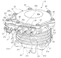
- FIG. 1 is an external perspective view showing the structure of a motor device (brushless motor) according to an embodiment of the present invention
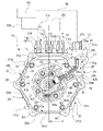
- FIG. 2 is a plan view showing the internal structure of the motor device shown in FIG. 1 with a cover member removed
- FIG. 3 is a cross-sectional view taken along line AA shown in FIG. 2
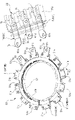
- FIG. 2 is a perspective view showing a busbar unit and a drive connector assembled to the motor device shown in FIG. 1
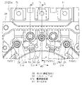
- FIG. 2 is a partial plan view showing the structure of a connecting portion between a bus bar unit and a drive connector in the motor device shown in FIG. 1
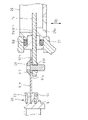
- FIG. 6 is a cross-sectional view taken along line BB shown in FIG. 5;
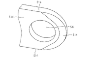
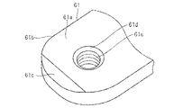
- FIG. 7 is a partial perspective view showing the tip shape of the power connection portion of the bus bar shown in FIG. 6; 7 is a partial perspective view showing the tip shape of the terminal of the drive connector shown in FIG. 6.
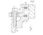
- FIG. 6 is a partial cross-sectional view taken along line CC shown in FIG. 5; FIG.
- the motor device shown in FIGS. 1 to 3 is a brushless motor 10 used as a drive source for an electric motorcycle or the like (a driven object).
- the brushless motor 10 is installed on the vehicle body frame and drives the axle of the drive wheel via a chain or belt. Note that the brushless motor 10 can also be directly provided on the axle of the drive wheel.
- the brushless motor 10 has a housing 20 that forms an outer shell of the brushless motor 10 .
- the housing 20 includes an aluminum housing body 21 formed in a substantially cylindrical shape with a bottom, and an aluminum cover member 22 formed in a substantially disk shape.
- the cover member 22 closes the opening side (the upper side in FIGS. 1 and 3) of the housing body 21 via a gasket 23 (see FIGS. 1 and 3) that functions as a sealing member.
- a motor unit 40 is housed inside the housing 20 .
- the motor unit 40 includes a stator 41 fixed inside the housing body 21 and a rotor 42 that rotates inside the stator 41 in the radial direction through a minute gap (air gap). That is, the stator 41 is housed in the housing 20 .
- the stator 41 has a stator core 41a formed in a substantially cylindrical shape by laminating a plurality of steel plates (magnetic bodies). A plurality of teeth (not shown) are provided inside the stator core 41a in the radial direction, and three phases of U, V and W are connected to these teeth via an insulator 41b made of a non-magnetic material such as plastic. Each coil 41c corresponding to the phase is wound by concentrated winding or the like. That is, the stator 41 is wound with a plurality of coils 41c.
- An annular busbar unit 50 is provided on one side of the stator 41 in the axial direction (upper side in the axial direction SD in FIG. 3).
- the busbar unit 50 has a plurality of busbars 51 . Further, the busbar unit 50 is electrically connected to the tip portions Tb (see FIG. 4) of the U-phase power supply terminal TU, the V-phase power supply terminal TV, and the W-phase power supply terminal TW.
- the busbar unit 50 has a function of distributing the drive current to each coil 41c corresponding to three phases of U phase, V phase and W phase.
- each of the U-phase power terminal TU, the V-phase power terminal TV, and the W-phase power terminal TW supplies drive currents to the respective coils 41c corresponding to the three phases of the U-phase, the V-phase, and the W-phase. .
- the rotor 42 rotates with respect to the stator 41 .
- the rotor 42 includes a rotor body 42a formed in a substantially tubular shape by laminating a plurality of steel plates (magnetic bodies).
- a rotary shaft 42b made of a round steel bar is fixed to the center of rotation of the rotor body 42a. That is, the rotating shaft 42b is rotated together with the rotor main body 42a.
- a plurality of plate-shaped magnets 42c are provided inside the rotor body 42a. The plurality of magnets 42c are arranged so that N poles and S poles appear alternately in the circumferential direction of the rotor body 42a.
- IPM Interior Permanent Magnet
- IPM Interior Permanent Magnet
- SPM Surface Permanent Magnet
- a sensor magnet 42d formed in a substantially disk shape is fixed to one side in the axial direction of the rotating shaft 42b that forms the rotor 42 .
- the sensor magnet 42d is used to detect the rotating state of the rotor 42 (rotating shaft 42b).
- the sensor magnet 42 d faces the rotation sensor 44 a provided on the sensor substrate 44 in the axial direction of the rotor 42 .
- One axial side of the rotating shaft 42b is rotatably supported by a first ball bearing BB1 attached to the bearing holder 43.
- the other axial side (lower side in FIG. 3) of the rotary shaft 42b is rotatably supported by a second ball bearing BB2 attached to the housing body 21. As shown in FIG.
- the housing main body 21 has a bottom wall portion 21a formed in a substantially disc shape.
- a substantially tubular bearing mounting portion 21b and a seal mounting portion 21c are integrally provided at the central portion of the bottom wall portion 21a.
- the bearing mounting portion 21b and the seal mounting portion 21c are coaxially arranged.
- the bearing mounting portion 21b is provided inside the housing body 21, and the outer ring of the second ball bearing BB2 is mounted radially inside the bearing mounting portion 21b.
- the seal mounting portion 21c is provided outside the housing body 21, and a rubber lip seal LS is mounted radially inside the seal mounting portion 21c.
- the inner ring of the second ball bearing BB2 is mounted on the other side of the rotating shaft 42b in the axial direction, and the lip seal LS is attached to the outer periphery of the rotating shaft 42b at a portion closer to the outer side of the housing body 21 than the second ball bearing BB2. have been contacted. This prevents rainwater, dust, and the like from entering the interior of the housing 20 .
- a total of four fixing legs 21d (only three are shown in FIGS. 1 and 2) are provided outside the housing body 21 and radially outside the bottom wall portion 21a. These fixed legs 21d are integrally provided around the bottom wall portion 21a at regular intervals (90-degree intervals), and are fixed to the body frame or the like forming the frame of the motorcycle via bolts.
- the housing main body 21 has a cylindrical wall portion 21e formed in a substantially cylindrical shape.
- the other axial side of the cylindrical wall portion 21e is provided integrally with the bottom wall portion 21a on the radially outer side.
- the stator core 41a is press-fitted inside the cylindrical wall portion 21e in the radial direction and is firmly fixed with an adhesive or the like.
- a plurality of cooling fins 21f are provided integrally on the radially outer side of the cylindrical wall portion 21e to dissipate the heat of the motor unit 40 (stator core 41a) generated by driving the brushless motor 10 to the outside of the housing body 21. It is
- the housing body 21 has a polygonal wall portion 24 .
- the polygonal wall portion 24 is integrally provided on one axial side (upper side in FIG. 3) of the tubular wall portion 21e so as to be coaxial with the tubular wall portion 21e. As shown in FIG. 2, the polygonal wall portion 24 is formed in a substantially regular hexagonal shape when the housing body 21 is viewed from one side in the axial direction.
- the polygonal wall portion 24 includes a first side portion 24a, a second side portion 24b, a third side portion 24c, a fourth side portion 24d, a fifth side portion 24e and a sixth side portion 24f. These six side portions 24a to 24f form a substantially regular hexagon.
- An opening 24g is provided in the polygonal wall portion 24, and the stator 41 and the rotor 42 (motor unit 40) are assembled inside the housing body 21 through the opening 24g. Further, the opening 24g is sealed by the cover member 22 with the gasket 23 interposed therebetween.
- a drive connector 25 which is a terminal unit, is attached to the first side portion 24a, and the drive connector 25 is provided on one side of the housing 20 in the axial direction.
- the drive connector 25 has a connector block 25a made of a resin material such as plastic. is fixed to the first side portion 24a of the polygonal wall portion 24 shown in FIG.
- the connector block 25a is arranged outside the housing 20, and more specifically protrudes radially outward from the polygonal wall portion 24. As shown in FIG. Each terminal 61 is provided inside the connector block 25a. Specifically, inside the connector block 25a, base ends Tt (see FIG. 4) of a U-phase power terminal TU, a V-phase power terminal TV, and a W-phase power terminal TW are exposed. Note that the tip portions Tb (see FIG. 4) of the U-phase power terminal TU, the V-phase power terminal TV, and the W-phase power terminal TW are electrically connected to the busbar unit 50 housed inside the housing 20, respectively. It is
- the tip portions Tb of the U-phase power terminal TU, the V-phase power terminal TV, and the W-phase power terminal TW are connected to the power connection portions 51e of the U-phase, V-phase, and W-phase bus bars 51. (see FIG. 4) are electrically connected to each other by fastening members.
- the electrical connection between each terminal 61 and each power supply connection portion 51e by means of a fastening member will be described later in detail.
- a base end portion Tt of the U-phase power supply terminal TU is electrically connected to a U-phase electric wire EU, one end of which is electrically connected to the controller CU and the other end of which is electrically connected to the controller CU.
- the base end Tt of the V-phase power supply terminal TV is electrically connected to the other end of the V-phase electric wire EV, one end of which is electrically connected to the controller CU.
- the base end Tt of the W-phase power supply terminal TW is electrically connected to the other end of the W-phase electric wire EW, one end of which is electrically connected to the controller CU.
- the drive current is supplied to each coil 41 c of the stator 41 .
- Each terminal 61 including the U-phase power terminal TU, the V-phase power terminal TV and the W-phase power terminal TW is, as shown in FIGS. It is arranged across the inner and outer sides of the portion 24 .
- the connector block 25a is oriented in a direction that intersects the axial direction of the housing 20 (upper side in FIG. 2). That is, the connecting directions of the other ends of the U-phase, V-phase, and W-phase electric wires EU, EV, and EW to the drive connector 25 are directions that cross the axial direction of the housing 20 .
- the connector block 25a is fixed to the first side portion 24a via a rubber seal member SM (see FIG. 3). This prevents rain water, dust, etc. from entering the housing 20 through the connector block 25a.
- the polygonal wall portion 24 is integrally provided with a protruding portion 26 that protrudes radially outward from the housing 20 .
- the protruding portion 26 protrudes radially outward of the housing 20 from a second side portion 24b provided adjacent to the first side portion 24a.
- the projecting portion 26 is formed in a substantially triangular shape when the housing 20 is viewed from one side in the axial direction, and includes an opening portion 26a and a bottom wall 26b formed in a substantially triangular shape.
- the projecting portion 26 has a first side wall 26c and a second side wall 26d standing on one side of the housing 20 in the axial direction from the bottom wall 26b.
- the second side portion 24b also stands on one side of the housing 20 in the axial direction from the bottom wall 26b.
- the projecting portion 26 is formed by being surrounded by the bottom wall 26b, the first side wall 26c, the second side wall 26d and the second side portion 24b, and the connection space SP is formed inside. That is, the connection space SP is provided on one side of the housing 20 in the axial direction.
- connection space SP is a portion into which the controller-side connector portion 47 side in the longitudinal direction of the board wire harness 45 enters.
- the connection space SP has a function of guiding (guiding) the controller-side connector portion 47 to the board connector 27 when connecting the controller-side connector portion 47 to the board connector 27 . This makes it possible to easily connect the controller-side connector portion 47 to the board connector 27 when assembling the brushless motor 10 .
- first side wall 26c is arranged substantially on an extension line of the first side portion 24a.
- second side wall 26d is arranged substantially on an extension line of the third side portion 24c. This prevents the projecting portion 26 from projecting radially outward of the housing 20 to a large extent.
- the opening 26 a of the projecting portion 26 is also sealed by the cover member 22 via the gasket 23 .
- the cover member 22 includes a main cover portion 22a that closes the opening 24g of the polygonal wall portion 24 and a sub-cover portion 22b that closes the opening 26a of the projecting portion 26. I have.
- the main cover portion 22a and the sub-cover portion 22b are integrated.
- the main cover portion 22a is formed in a substantially disc shape, and the sub-cover portion 22b is formed in a substantially triangular plate shape.
- the cover member 22 is firmly fixed to the housing body 21 by a total of seven fixing bolts BT distributed in the circumferential direction.
- a gasket 23 is sandwiched between them.
- a connector fixing portion 26e is integrally provided on the first side wall 26c of the protruding portion 26 so as to protrude radially outward of the housing 20 .
- a board connector 27 is attached to the connector fixing portion 26e.
- the board connector 27 is also provided on one axial side of the housing 20 in the same manner as the drive connector 25 .
- the board connector 27 is formed in a predetermined shape from a resin material such as plastic, and includes a fixed plate portion 27a formed in a substantially flat plate shape.
- the fixed plate portion 27a is fixed to the connector fixing portion 26e by a pair of first screws S1.
- a rubber sealing member (not shown) is provided between the fixing plate portion 27a and the connector fixing portion 26e. This prevents rain water, dust, and the like from entering the housing 20 through the board connector 27 .
- the board connector 27 has an inner connecting portion (not shown) and an outer connecting portion 27c which are formed in a substantially box shape.
- the inner connecting portion is provided on the connector fixing portion 26 e side of the fixing plate portion 27 a and arranged inside the housing 20 .
- the outer connection portion 27c is provided on the opposite side of the fixing plate portion 27a to the connector fixing portion 26e side and arranged outside the housing 20 .
- a plurality of conductive members are embedded inside the board connector 27 by insert molding or the like.
- the controller-side connector portion 47 of the board wire harness 45 is connected to the inner connecting portion of the board connector 27 in the connection space SP inside the projecting portion 26 .
- the other end of the board electric wire SE (see FIG. 2), one end of which is electrically connected to the controller CU, is connected to the connector connection portion (not shown). connected through That is, the other end side of the board electric wire SE is electrically connected to one end side of the conductive member provided inside the board connector 27 .
- the connector block 25a arranged outside the housing 20 and the outer connection portion 27c arranged outside the housing 20 intersect the axial direction of the housing 20, respectively. and facing the same direction (upward in FIG. 2).
- the drive connector 25 and the board connector 27 are arranged in a horizontal row in a direction intersecting the axial direction of the housing 20 when the housing 20 is viewed from the direction intersecting the axial direction.
- the drive connector 25 and the board connector 27 are within the range of the axial dimension of the rotor 42, that is, the range of the axial dimension of the rotating shaft 42b when the housing 20 is viewed from the direction intersecting the axial direction thereof. (see FIG. 3).
- the axial dimension of the brushless motor 10 is reduced, and the miniaturization of the brushless motor 10 is realized.
- a substantially regular hexagonal plate-like aluminum bearing holder 43 is provided on one axial side of the housing body 21 (the upper side in FIG. 3).
- the bearing holder 43 is arranged radially inside the polygonal wall portion 24 formed in a substantially regular hexagon, and holds the first ball bearing BB1.
- the first ball bearing BB1 is attached to a holding cylinder 43a formed in the central portion of the bearing holder 43.
- the holding tube 43 a protrudes toward the other axial side (lower side in FIG. 3 ) of the housing body 21 and enters the busbar unit 50 radially inward. This also reduces the axial dimension of the brushless motor 10 .
- the bearing holder 43 is firmly fixed to one axial side of the housing body 21 by a total of six first fixing bolts B1.
- a total of six first fixing bolts B1 are distributed so as to be positioned near the corners of the bearing holder 43 and are tightened from one side of the housing body 21 in the axial direction. This effectively suppresses the distortion of the bearing holder 43 and ensures the positional accuracy of the first ball bearing BB1. Therefore, smooth rotation of the rotor 42 becomes possible.
- the first fixing bolt B1 is provided inside the housing 20, but even if it were loosened and removed, it would not come off to the rotor 42 side, thus reliably preventing damage to the rotating part.
- a substantially plate-shaped clip fixing portion 43b is provided on the opposite side of the bearing holder 43 from the rotor 42 side and in the vicinity of the projecting portion 26 .
- the clip fixing portion 43b is arranged between the adjacent first fixing bolts B1 and protrudes to one axial side of the housing 20 (the front side in FIG. 2).
- a clip member 49 fixed to the substrate wire harness 45 is fixed to the clip fixing portion 43b.
- annular support plate 43c is provided to prevent the first ball bearing BB1 from coming off from the holding tube 43a. Specifically, the support plate 43c presses the outer ring of the first ball bearing BB1 at its radially inner portion. This ensures smooth operation of the first ball bearing BB1.
- the support plate 43c is fixed to the bearing holder 43 by a total of four second fixing bolts B2 (only three are shown in FIG. 2) arranged at equal intervals (at intervals of 90 degrees) in the circumferential direction of the support plate 43c. It is Here, the second fixing bolt B2 is also provided inside the housing 20, but even if it is loosened and comes off, it will not come off to the side of the rotor 42, and damage to the rotating portion can be reliably prevented.
- a total of four support columns 43d are provided on the opposite side of the bearing holder 43 from the rotor 42 side and around the first ball bearing BB1. Each of these support columns 43d protrudes at a predetermined height from one side of the housing 20 in the axial direction, and the sensor substrate 44 is fixed to the tip portion thereof. That is, a total of four support columns 43d support the sensor substrate 44. As shown in FIG.
- the respective support columns 43d are arranged at equal intervals (90 degree intervals) around the first ball bearing BB1, and a pair of second screws S2 are attached to a pair of support columns 43d arranged on a diagonal line.
- the sensor substrate 44 is fixed by .
- the second screw S2 is also provided inside the housing 20, even if it were loosened and removed, it would not come off toward the rotor 42, thereby reliably preventing damage to the rotating portion.
- the sensor board 44 supported by a total of four support columns 43d is provided on one side in the axial direction of the housing 20 and is a printed circuit board (PCB) formed in a substantially square shape.
- a rotation sensor 44a made of a magnetoresistive element is provided in the central portion of the sensor substrate 44. As shown in FIG. In the axial direction of the housing 20, the rotation sensor 44a faces a sensor magnet 42d fixed to one axial side of the rotary shaft 42b with a minute gap therebetween (see FIG. 3). Thereby, the rotation sensor 44a detects the rotation state (rotation direction, rotation speed, etc.) of the rotation shaft 42b.
- the sensor board 44 is provided with a board-side connection portion 44b to which the board-side connector portion 48 of the board wire harness 45 is connected. As shown in FIG. 2, the board-side connection portion 44b provided on the sensor board 44 faces the connection space SP of the projecting portion 26, thereby connecting the board-side connector portion 48 to the board side. It is possible to easily connect to the portion 44b.
- the board wire harness 45 is provided between the sensor board 44 and the board connector 27 , and the board wire harness 45 is connected to the controller CU (see FIG. 2 ) and the sensor board 44 inside the housing 20 . It has the function of electrically connecting the Therefore, the detection signal of the rotation sensor 44a is sent to the controller CU via the board wire harness 45 and the board wire SE.
- the busbar unit 50 provided on one axial side of the stator 41 is formed in a substantially annular shape when viewed in the axial direction.
- a holding cylinder 43a is arranged inside the busbar unit 50 in the radial direction when the brushless motor 10 is assembled. Therefore, the first ball bearing BB1 and part of the rotating shaft 42b are also arranged radially inside the busbar unit 50 .
- the busbar unit 50 has a total of three busbars 51 formed in a substantially C-shape when viewed in the axial direction. 3), they are for U-phase, V-phase and W-phase, respectively. In addition, the three bus bars 51 are formed in the same shape.
- the busbar unit 50 also includes a busbar support portion 52 that holds busbars 51 for the U-phase, V-phase, and W-phase.
- the busbar support portion 52 corresponds to an insulator in the present invention, and is formed in an annular shape by injection molding a resin material such as plastic. Specifically, as shown in FIG. 4, the busbar support portion 52 displaces the three busbars 51 by a predetermined amount (approximately 30 degrees) in the circumferential direction and is in a non-contact state (not short-circuited). state).
- the three busbars 51 are superimposed on each other in an insulated state in the axial direction of the busbar unit 50 with a minute gap therebetween. Therefore, the distortion of each busbar 51 is an event that should be reliably eliminated in manufacturing the busbar unit 50 .
- the busbars 51 in order to reduce the axial dimension of the busbar unit 50 and to reduce the size of the brushless motor 10 as a whole, the busbars 51 must be formed with high precision so as not to be distorted.
- Each busbar 51 has a first arc portion (arc portion) 51a and a second arc portion (arc portion) 51b formed in an arc shape when viewed in the axial direction of the busbar 51, and a first arc portion 51a and a second arc portion. and a power connection portion 51e projecting radially outward from each of the portions 51b.
- the busbar 51 has a first arcuate portion 51a formed in a substantially arcuate shape when viewed in the axial direction of the busbar 51 .
- the first circular arc portion 51 a occupies most of the busbar 51 .
- the busbar 51 also includes a second arc portion 51b formed in a substantially arc shape when viewed in the axial direction of the busbar 51 .
- the second arc portion 51b has the same radius of curvature as the first arc portion 51a.
- Coil connecting portions 51c are integrally provided on both sides in the longitudinal direction of the first arc portion 51a and one side in the longitudinal direction of the second arc portion 51b, respectively. That is, the busbar 51 is provided with a total of three coil connection portions 51c. The interval between the pair of coil connection portions 51c provided on the first circular arc portion 51a is 180 degrees. The interval between the coil connecting portion 51c on the other longitudinal side of the first arc portion 51a and the coil connecting portion 51c of the second arc portion 51b is 90 degrees.
- the distal end portions Tb of the U-phase power terminal TU, the V-phase power terminal TV, and the W-phase power terminal TW are electrically connected to the distal end portion Tp on the distal end side in the longitudinal direction of the power supply connection portion 51e. It has become.
- each terminal 61 of the present embodiment and the power connection portion 51e corresponding to each terminal 61 by means of a fastening member will be described in detail.
- the U-phase power terminal TU (61) and the power connection portion 51e are arranged so as to overlap each other in the axial direction RD of the rotor 42 shown in FIG.
- the U-phase power supply terminal TU (61) and the power supply connection portion 51e are electrically connected by screwing a fixing bolt 28 as a fastening member.
- the V-phase power terminal TV (61) and the power connection portion 51e are arranged so as to overlap each other in the axial direction RD of the rotor . As shown in FIG.
- the V-phase power supply terminal TV (61) and the power supply connection portion 51e are electrically connected by screwing a bolt 28 as a fastening member. Further, the W-phase power terminal TW (61) and the power connection portion 51e are arranged so as to overlap each other in the axial direction RD of the rotor . As shown in FIG. 5, the W-phase power supply terminal TW (61) and the power supply connection portion 51e are electrically connected by screwing a bolt 28 as a fastening member.
- connection structure between each terminal 61 and the power supply connection portion 51e will be described by taking the connection structure between the V-phase power supply terminal TV (61) and the power supply connection portion 51e as a representative example.
- connection structure between the U-phase power supply terminal TU (61) and the power supply connection part 51e and the connection structure between the W-phase power supply terminal TW (61) and the power supply connection part 51e also differ from the V-phase power supply terminal TV ( 61) and the power connection portion 51e.
- the tip of the power supply connection part 51e is placed on the tip end of the V-phase power supply terminal TV (61).
- the bolt 28 inserted through the through hole 51i of the power supply connection portion 51e from above the power supply connection portion 51e and the screw groove shown in FIG. 61e are screwed together.
- the V-phase power terminal TV (61) and the power connection portion 51e are electrically connected.
- the power supply connection portion 51e is arranged on the V-phase power supply terminal TV (61), and the bolt 28 inserted into the through hole 51i of the power supply connection portion 51e and the V It is screwed to the thread groove 61e of the phase power terminal TV (61).
- a screw hole 61d shown in FIG. 8 is formed in the V-phase power terminal TV (61), while a through hole 51i shown in FIG. formed.
- the bolt 28 inserted into the through hole 51i of the power supply connection portion 51e and the screw groove 61e of the V-phase power supply terminal TV (61) are screwed together, thereby connecting the V-phase power supply terminal TV (61) and the power supply. It is electrically connected to the connecting portion 51e.
- the relationship between the V-phase power terminal TV (61) and the power connection portion 51e may be reversed. That is, the V-phase power supply terminal TV (61) is superimposed on the power supply connection part 51e, and is inserted from above the V-phase power supply terminal TV (61) through the through-hole of the V-phase power supply terminal TV (61).
- the bolt 28 formed on the power supply connection portion 51e may be screwed into a screw groove formed in the power supply connection portion 51e, thereby electrically connecting the power supply connection portion 51e and the V-phase power supply terminal TV (61).
- each terminal 61 is connected to the power supply connection portion 51e corresponding to each terminal 61 by screw connection using the bolt 28, so that welding or the like is performed.
- the power connection portion (terminal) 51e of the bus bar 51 and each terminal 61 of the terminal unit (drive connector 25) can be electrically connected without using large-scale equipment.
- each terminal 61 and the power supply connection portion 51e corresponding to each terminal 61 is achieved by screwing a fastening member such as a bolt 28, thereby ensuring a larger connection area than welding. can be done.
- a fastening member such as a bolt 28
- the current density of the current flowing through the connection portion between the terminal 61 and the power supply connection portion 51e can be reduced.
- the brushless motor 10 mounted on a motorcycle or the like carries a large amount of current, the resistance increases when the area of the terminal connection portion becomes small and the current density increases.
- heat generation at the connecting portion increases and may exceed the heat resistance temperature of the coil coating, or the heat generation may increase and adversely affect the insert mold resin. Therefore, it is preferable that the current density in the connecting portion of the terminal or the like is low. In welding, there is a possibility that a necessary and sufficient connection area (cross-sectional area) cannot be ensured at a connection part of a terminal or the like.
- the electrical connection between the terminal 61 and the power supply connection portion 51e is achieved by the screw connection of the fastening member, so that a large connection area can be secured at the connection portion and the like. , the current density of the current flowing through the connection can be reduced. As a result, it is possible to prevent the heat generation at the connection portion from increasing during operation and exceeding the heat resistance temperature of the coil coating, and furthermore, it is possible to prevent the insert mold resin from being adversely affected by the large heat generation. .
- the electrical connection between the terminal 61 and the power supply connection portion 51e is achieved by the screw connection of the fastening member, and welding is not performed, thereby eliminating the need for a welding machine and an image recognition camera, thereby reducing the number of equipment to be used. be able to.
- electrical connection between the terminal 61 and the power supply connection portion 51e is performed by screwing the fastening member, and welding is not performed. It is possible to reduce the use of machine tools and reduce the driving energy of the welding machine for welding. As a result, it becomes possible to achieve goals 7 and 13 in particular of the Sustainable Development Goals (SDGs) set by the United Nations.
- SDGs Sustainable Development Goals
- the portion forming the screw groove 61e (see FIG. 8) of the V-phase power supply terminal TV (61) is a burning portion formed by performing a burning process and a tapping process. 61f is provided.
- the V-phase power supply terminal TV (61) is inserted from the outside of the housing body 21 toward the busbar unit 50 inside the housing body 21, and the tip side end of the V-phase power terminal TV (61) and the tip side end of the power supply connection part 51e are connected. pile up.
- the front end side peripheral edge portion 51f front end portion A chamfered portion 51h is formed on the peripheral portion on the Tp side.
- a chamfered portion 61c is formed on the tip side peripheral edge portion 61b (the peripheral edge portion on the tip Tb side) of the surface (facing surface 61a) of the terminal 61 that overlaps the power connection portion 51e.
- a chamfered portion 51h is formed on the tip side peripheral edge portion 51f of the facing surface 51d of the power supply connection portion 51e
- a chamfered portion 61c is formed on the tip side peripheral edge portion 61b of the facing surface 61a of the terminal 61.
- the V-phase power terminal TV (61) is inserted from the outside of the housing main body 21, and the tip end Tb side of the V-phase power terminal TV (61) and the tip Tp side of the power connection portion 51e are connected.
- the chamfered portion 51h of the power supply connection portion 51e and the chamfered portion 61c of the V-phase power supply terminal TV (61) allow the terminal 61 and the power supply connection portion 51e to be smoothly overlapped. Therefore, even if the terminal 61 and the power supply connection part 51e run on top of each other, it is possible to assemble the terminal 61 and the power supply connection part 51e.
- a connector block (connector) 25a for holding each terminal 61 is provided outside the polygonal wall portion 24 of the housing 20 (see FIG. 3).
- the power supply connection portions 51e provided in each of the three bus bars 51 (see FIG. 4) two power supply connection portions 51e arranged adjacent to the first circular arc portion 51a (see FIG. 4) in the circumferential direction AD.
- a mounting portion 25b of a connector block (connector) 25a is arranged at a position between . That is, in the structure shown in FIG. 5, a plate-like mounting portion 25b provided on the connector block 25a is arranged between two power supply connection portions 51e arranged adjacent to each other in the circumferential direction AD.
- the plate-like mounting portion 25b is inserted from the outside to the inside of the polygonal wall portion 24 of the housing 20 and arranged between two adjacent power supply connection portions 51e.
- the plate-shaped mounting portion 25b is screwed and fixed to the housing body 21 of the housing 20 via bolts (another fastening member) 53, as shown in FIG. Specifically, a bolt 53 is passed through an insert member 54 embedded in the mounting portion 25b, and is screwed into a screw groove 21g formed in the housing body 21. As shown in FIG. In other words, the connector block 25a is screwed to the housing body 21 with the bolts 53 via the plate-like mounting portion 25b.
- the terminal unit By arranging the mounting portion 25b of the connector block 25a of the terminal unit between the two power supply connection portions 51e arranged adjacent to each other in the circumferential direction AD, the terminal unit can be installed by efficiently utilizing the space. It can be attached to the housing body 21 .
- the brushless motor 10 having the busbar unit 50 is applied to a drive source such as an electric motorcycle, but the present invention is not limited to this.
- a drive source such as an electric motorcycle
- the present invention is not limited to this.
- it can be applied to drive sources of small mobility such as electric wheelchairs and electric pushcarts, drive sources such as joints of arm robots, and drive sources of power steering devices.
- the terminal 61 is subjected to a burning process to form a burning portion. Burning may not be applied if it can be secured.
- each component in the above embodiment is arbitrary as long as the present invention can be achieved, and are not limited to the above embodiment.
- 10 brushless motor (motor device), 20: housing, 21: housing body, 21a: bottom wall portion, 21b: bearing mounting portion, 21c: seal mounting portion, 21d: fixed leg, 21e: cylindrical wall portion, 21f: Cooling fin, 21g: thread groove, 22: cover member, 22a: main cover portion, 22b: sub-cover portion, 23: gasket, 24: polygonal wall portion, 24a: first side portion, 24b: second side portion, 24c: third side, 24d: fourth side, 24e: fifth side, 24f: sixth side, 24g: opening, 25: drive connector (terminal unit), 25a: connector block (connector) , 25b: mounting portion, 26: projecting portion, 26a: opening, 26b: bottom wall, 26c: first side wall, 26d: second side wall, 26e: connector fixing portion, 27: substrate connector, 27a: fixing plate portion , 27c: outer connection portion, 28: bolt (fastening member), 40: motor unit, 41: stator, 41a: stator core, 41b: stat
Landscapes
- Engineering & Computer Science (AREA)
- Power Engineering (AREA)
- Motor Or Generator Frames (AREA)
- Windings For Motors And Generators (AREA)
- Insulation, Fastening Of Motor, Generator Windings (AREA)
Abstract
Description
Claims (4)
- ハウジングに収容され、コイルが巻装されたステータと、
前記ステータに対して回転するロータと、
前記ステータの軸方向一側に設けられ、複数のバスバーを備えたバスバーユニットと、
前記コイルに駆動電流を供給するターミナルと、
を有するモータ装置であって、
前記バスバーは、
円弧形状に形成された円弧部と、
前記円弧部の径方向外側に突出された電源接続部と、
を備え、
前記ターミナルは、前記ハウジングの内側と外側とに跨って配置され、
前記電源接続部と前記ターミナルは、前記ロータの軸方向に重ねられて配置され、かつ締結部材によって電気的に接続されていることを特徴とするモータ装置。 - 前記電源接続部の前記ターミナルと重なる面の先端側周縁部に面取り部が形成され、
前記ターミナルの前記電源接続部と重なる面の先端側周縁部に面取り部が形成されていることを特徴とする請求項1に記載のモータ装置。 - 前記ターミナルにねじ孔が形成され、
前記電源接続部に前記ねじ孔より大きな直径の貫通孔が形成され、
前記貫通孔に通した固定用のボルトと前記ねじ孔に形成されたねじ溝とがねじ結合されていることを特徴とする請求項1または請求項2に記載のモータ装置。 - 前記ターミナルを保持するコネクタが前記ハウジングの外側に設けられ、
前記複数のバスバーのそれぞれが備える前記電源接続部のうち、前記円弧部の周方向に隣接して配置された2つの前記電源接続部の間に、前記コネクタの取付部が配置され、
前記取付部は、他の締結部材を介して前記ハウジングに固定されていることを特徴とする請求項1から請求項3のいずれか1項に記載のモータ装置。
Priority Applications (1)
| Application Number | Priority Date | Filing Date | Title |
|---|---|---|---|
| CN202280007322.1A CN116472659A (zh) | 2021-07-12 | 2022-06-27 | 马达装置 |
Applications Claiming Priority (2)
| Application Number | Priority Date | Filing Date | Title |
|---|---|---|---|
| JP2021115268A JP7672296B2 (ja) | 2021-07-12 | 2021-07-12 | モータ装置 |
| JP2021-115268 | 2021-07-12 |
Publications (1)
| Publication Number | Publication Date |
|---|---|
| WO2023286573A1 true WO2023286573A1 (ja) | 2023-01-19 |
Family
ID=84920041
Family Applications (1)
| Application Number | Title | Priority Date | Filing Date |
|---|---|---|---|
| PCT/JP2022/025477 Ceased WO2023286573A1 (ja) | 2021-07-12 | 2022-06-27 | モータ装置 |
Country Status (3)
| Country | Link |
|---|---|
| JP (1) | JP7672296B2 (ja) |
| CN (1) | CN116472659A (ja) |
| WO (1) | WO2023286573A1 (ja) |
Families Citing this family (1)
| Publication number | Priority date | Publication date | Assignee | Title |
|---|---|---|---|---|
| JP2025150767A (ja) * | 2024-03-27 | 2025-10-09 | 株式会社ミツバ | モータ及びファン装置 |
Citations (9)
| Publication number | Priority date | Publication date | Assignee | Title |
|---|---|---|---|---|
| JP2003134725A (ja) * | 2001-10-26 | 2003-05-09 | Sumitomo Wiring Syst Ltd | 車両用薄型ブラシレスモータの集中配電部材 |
| JP2006353017A (ja) * | 2005-06-16 | 2006-12-28 | Toyota Motor Corp | 回転電機 |
| JP2009124902A (ja) * | 2007-11-16 | 2009-06-04 | Hitachi Ltd | 回転電機およびそれを備えた車載用電機システム |
| JP2012170241A (ja) * | 2011-02-15 | 2012-09-06 | Honda Motor Co Ltd | 回転電機 |
| JP2013046498A (ja) * | 2011-08-24 | 2013-03-04 | Sumitomo Wiring Syst Ltd | モータの集中配電部材 |
| JP2014116259A (ja) * | 2012-12-12 | 2014-06-26 | Suzuki Motor Corp | 端子台の周辺構造 |
| JP2015142429A (ja) * | 2014-01-28 | 2015-08-03 | 日本精工株式会社 | ブラシレスモータ及び電動パワーステアリング装置 |
| JP2019187079A (ja) * | 2018-04-10 | 2019-10-24 | 株式会社デンソー | 駆動装置 |
| JP2021087322A (ja) * | 2019-11-29 | 2021-06-03 | アイシン・エィ・ダブリュ株式会社 | 回転電機用の端子ユニットおよび駆動モジュール |
-
2021
- 2021-07-12 JP JP2021115268A patent/JP7672296B2/ja active Active
-
2022
- 2022-06-27 WO PCT/JP2022/025477 patent/WO2023286573A1/ja not_active Ceased
- 2022-06-27 CN CN202280007322.1A patent/CN116472659A/zh active Pending
Patent Citations (9)
| Publication number | Priority date | Publication date | Assignee | Title |
|---|---|---|---|---|
| JP2003134725A (ja) * | 2001-10-26 | 2003-05-09 | Sumitomo Wiring Syst Ltd | 車両用薄型ブラシレスモータの集中配電部材 |
| JP2006353017A (ja) * | 2005-06-16 | 2006-12-28 | Toyota Motor Corp | 回転電機 |
| JP2009124902A (ja) * | 2007-11-16 | 2009-06-04 | Hitachi Ltd | 回転電機およびそれを備えた車載用電機システム |
| JP2012170241A (ja) * | 2011-02-15 | 2012-09-06 | Honda Motor Co Ltd | 回転電機 |
| JP2013046498A (ja) * | 2011-08-24 | 2013-03-04 | Sumitomo Wiring Syst Ltd | モータの集中配電部材 |
| JP2014116259A (ja) * | 2012-12-12 | 2014-06-26 | Suzuki Motor Corp | 端子台の周辺構造 |
| JP2015142429A (ja) * | 2014-01-28 | 2015-08-03 | 日本精工株式会社 | ブラシレスモータ及び電動パワーステアリング装置 |
| JP2019187079A (ja) * | 2018-04-10 | 2019-10-24 | 株式会社デンソー | 駆動装置 |
| JP2021087322A (ja) * | 2019-11-29 | 2021-06-03 | アイシン・エィ・ダブリュ株式会社 | 回転電機用の端子ユニットおよび駆動モジュール |
Also Published As
| Publication number | Publication date |
|---|---|
| JP7672296B2 (ja) | 2025-05-07 |
| JP2023011426A (ja) | 2023-01-24 |
| CN116472659A (zh) | 2023-07-21 |
Similar Documents
| Publication | Publication Date | Title |
|---|---|---|
| CN115211003B (zh) | 电动驱动装置、电动助力转向装置和电子控制装置的制造方法 | |
| CN107921995B (zh) | 电动驱动装置及电动助力转向装置 | |
| JP3612715B2 (ja) | モータ及びその製造方法 | |
| US9048716B2 (en) | Motor including specific magnetic sensor arrangement | |
| US8564161B1 (en) | Motorized equipment | |
| JP5942967B2 (ja) | 駆動装置 | |
| CN107921997B (zh) | 电动驱动装置及电动助力转向装置 | |
| JP4688910B2 (ja) | 電動パワーステアリング装置用モータ | |
| US7683516B2 (en) | Production method for rotating electric machine and stator coils, and electric power steering motor | |
| US8310119B2 (en) | Electric motor | |
| JP7264315B2 (ja) | 電動駆動装置及び電動パワーステアリング装置 | |
| JP5235085B2 (ja) | ステータ及びブラシレスモータ | |
| CN107921996B (zh) | 电动驱动装置及电动助力转向装置 | |
| US20160218578A1 (en) | Bus bar unit, method for manufacturing bus bar unit, and brushless motor | |
| JP2018207640A (ja) | 電動駆動装置、及び電動パワーステアリング装置 | |
| JP6514136B2 (ja) | 電動駆動装置及び電動パワーステアリング装置 | |
| WO2015122069A1 (ja) | 制御装置付き回転電機、電動パワーステアリング装置および制御装置付き回転電機の製造方法 | |
| JP2014183615A (ja) | 回転電機 | |
| JPWO2020067255A1 (ja) | モータ | |
| JP6922435B2 (ja) | 電動駆動装置、及び電動パワーステアリング装置 | |
| JP7672296B2 (ja) | モータ装置 | |
| JP6838254B2 (ja) | 電動駆動装置 | |
| JP2011083062A (ja) | モータユニット | |
| WO2009048181A1 (en) | Motor | |
| JP7548876B2 (ja) | モータ装置 |
Legal Events
| Date | Code | Title | Description |
|---|---|---|---|
| 121 | Ep: the epo has been informed by wipo that ep was designated in this application |
Ref document number: 22841917 Country of ref document: EP Kind code of ref document: A1 |
|
| WWE | Wipo information: entry into national phase |
Ref document number: 202280007322.1 Country of ref document: CN |
|
| WWE | Wipo information: entry into national phase |
Ref document number: 202317035868 Country of ref document: IN |
|
| NENP | Non-entry into the national phase |
Ref country code: DE |
|
| 122 | Ep: pct application non-entry in european phase |
Ref document number: 22841917 Country of ref document: EP Kind code of ref document: A1 |