WO2023286441A1 - Dehydrogenation device, system for manufacturing steel sheet, and method for manufacturing steel sheet - Google Patents
Dehydrogenation device, system for manufacturing steel sheet, and method for manufacturing steel sheet Download PDFInfo
- Publication number
- WO2023286441A1 WO2023286441A1 PCT/JP2022/020580 JP2022020580W WO2023286441A1 WO 2023286441 A1 WO2023286441 A1 WO 2023286441A1 JP 2022020580 W JP2022020580 W JP 2022020580W WO 2023286441 A1 WO2023286441 A1 WO 2023286441A1
- Authority
- WO
- WIPO (PCT)
- Prior art keywords
- steel sheet
- coil
- less
- steel
- rolled
- Prior art date
Links
- 229910000831 Steel Inorganic materials 0.000 title claims abstract description 955
- 239000010959 steel Substances 0.000 title claims abstract description 955
- 238000004519 manufacturing process Methods 0.000 title claims abstract description 133
- 238000006356 dehydrogenation reaction Methods 0.000 title claims abstract description 131
- 238000000034 method Methods 0.000 title claims abstract description 82
- 229910052739 hydrogen Inorganic materials 0.000 claims abstract description 139
- 239000001257 hydrogen Substances 0.000 claims abstract description 139
- UFHFLCQGNIYNRP-UHFFFAOYSA-N Hydrogen Chemical compound [H][H] UFHFLCQGNIYNRP-UHFFFAOYSA-N 0.000 claims abstract description 134
- 238000004804 winding Methods 0.000 claims abstract description 72
- 230000004308 accommodation Effects 0.000 claims abstract description 5
- 238000000137 annealing Methods 0.000 claims description 161
- 239000010960 cold rolled steel Substances 0.000 claims description 114
- 238000007747 plating Methods 0.000 claims description 73
- 238000010438 heat treatment Methods 0.000 claims description 51
- 238000005246 galvanizing Methods 0.000 claims description 38
- 230000008569 process Effects 0.000 claims description 33
- 238000005097 cold rolling Methods 0.000 claims description 23
- 239000000203 mixture Substances 0.000 claims description 21
- 238000005098 hot rolling Methods 0.000 claims description 19
- 238000005275 alloying Methods 0.000 claims description 18
- 239000010935 stainless steel Substances 0.000 claims description 15
- 229910001220 stainless steel Inorganic materials 0.000 claims description 15
- 239000000126 substance Substances 0.000 claims description 13
- 229910052726 zirconium Inorganic materials 0.000 claims description 10
- 238000013016 damping Methods 0.000 claims description 9
- 238000009713 electroplating Methods 0.000 claims description 7
- 239000012535 impurity Substances 0.000 claims description 5
- 238000003860 storage Methods 0.000 claims description 5
- 229910001335 Galvanized steel Inorganic materials 0.000 description 41
- 239000008397 galvanized steel Substances 0.000 description 41
- 238000001816 cooling Methods 0.000 description 37
- 238000005096 rolling process Methods 0.000 description 28
- 230000007797 corrosion Effects 0.000 description 22
- 238000005260 corrosion Methods 0.000 description 22
- 230000000694 effects Effects 0.000 description 22
- 239000000047 product Substances 0.000 description 15
- 238000012360 testing method Methods 0.000 description 14
- 238000005452 bending Methods 0.000 description 13
- 238000002791 soaking Methods 0.000 description 12
- 238000011282 treatment Methods 0.000 description 12
- 238000009792 diffusion process Methods 0.000 description 10
- 238000005728 strengthening Methods 0.000 description 10
- 238000010586 diagram Methods 0.000 description 9
- 229910052761 rare earth metal Inorganic materials 0.000 description 9
- 150000002910 rare earth metals Chemical class 0.000 description 9
- 239000011248 coating agent Substances 0.000 description 8
- 238000000576 coating method Methods 0.000 description 8
- 238000011144 upstream manufacturing Methods 0.000 description 8
- 229910052720 vanadium Inorganic materials 0.000 description 8
- 229910052758 niobium Inorganic materials 0.000 description 7
- 230000009467 reduction Effects 0.000 description 7
- HCHKCACWOHOZIP-UHFFFAOYSA-N Zinc Chemical compound [Zn] HCHKCACWOHOZIP-UHFFFAOYSA-N 0.000 description 6
- 229910052799 carbon Inorganic materials 0.000 description 6
- 239000007789 gas Substances 0.000 description 6
- 229910052749 magnesium Inorganic materials 0.000 description 6
- 239000000463 material Substances 0.000 description 6
- 229910052750 molybdenum Inorganic materials 0.000 description 6
- 229910052725 zinc Inorganic materials 0.000 description 6
- 239000011701 zinc Substances 0.000 description 6
- 229910052804 chromium Inorganic materials 0.000 description 5
- 150000002431 hydrogen Chemical class 0.000 description 5
- 238000001556 precipitation Methods 0.000 description 5
- 239000006104 solid solution Substances 0.000 description 5
- 229910052718 tin Inorganic materials 0.000 description 5
- 229910052791 calcium Inorganic materials 0.000 description 4
- 238000005516 engineering process Methods 0.000 description 4
- 229910052759 nickel Inorganic materials 0.000 description 4
- 229910052757 nitrogen Inorganic materials 0.000 description 4
- 239000002244 precipitate Substances 0.000 description 4
- 230000003746 surface roughness Effects 0.000 description 4
- UCKMPCXJQFINFW-UHFFFAOYSA-N Sulphide Chemical compound [S-2] UCKMPCXJQFINFW-UHFFFAOYSA-N 0.000 description 3
- 230000002411 adverse Effects 0.000 description 3
- 239000002585 base Substances 0.000 description 3
- 238000005336 cracking Methods 0.000 description 3
- 230000006866 deterioration Effects 0.000 description 3
- 238000007599 discharging Methods 0.000 description 3
- 238000006073 displacement reaction Methods 0.000 description 3
- 230000006872 improvement Effects 0.000 description 3
- 238000009434 installation Methods 0.000 description 3
- 229910000734 martensite Inorganic materials 0.000 description 3
- 150000001247 metal acetylides Chemical class 0.000 description 3
- 238000005381 potential energy Methods 0.000 description 3
- 238000005204 segregation Methods 0.000 description 3
- 229910052715 tantalum Inorganic materials 0.000 description 3
- 229910052721 tungsten Inorganic materials 0.000 description 3
- 230000032683 aging Effects 0.000 description 2
- 229910045601 alloy Inorganic materials 0.000 description 2
- 239000000956 alloy Substances 0.000 description 2
- 230000003321 amplification Effects 0.000 description 2
- 230000015572 biosynthetic process Effects 0.000 description 2
- 238000007664 blowing Methods 0.000 description 2
- 238000004364 calculation method Methods 0.000 description 2
- 239000003795 chemical substances by application Substances 0.000 description 2
- 238000009749 continuous casting Methods 0.000 description 2
- 229910052802 copper Inorganic materials 0.000 description 2
- 238000012937 correction Methods 0.000 description 2
- 230000007547 defect Effects 0.000 description 2
- 230000003111 delayed effect Effects 0.000 description 2
- 239000004615 ingredient Substances 0.000 description 2
- 230000000977 initiatory effect Effects 0.000 description 2
- 229910052748 manganese Inorganic materials 0.000 description 2
- 238000003199 nucleic acid amplification method Methods 0.000 description 2
- 238000004806 packaging method and process Methods 0.000 description 2
- 238000002161 passivation Methods 0.000 description 2
- 238000003825 pressing Methods 0.000 description 2
- 238000012545 processing Methods 0.000 description 2
- 238000003303 reheating Methods 0.000 description 2
- 239000011347 resin Substances 0.000 description 2
- 229920005989 resin Polymers 0.000 description 2
- 229920006395 saturated elastomer Polymers 0.000 description 2
- 229910052717 sulfur Inorganic materials 0.000 description 2
- 238000009864 tensile test Methods 0.000 description 2
- 150000003568 thioethers Chemical class 0.000 description 2
- 241000219307 Atriplex rosea Species 0.000 description 1
- 230000009471 action Effects 0.000 description 1
- 239000003513 alkali Substances 0.000 description 1
- 229910001566 austenite Inorganic materials 0.000 description 1
- 230000005540 biological transmission Effects 0.000 description 1
- 239000004566 building material Substances 0.000 description 1
- 230000008859 change Effects 0.000 description 1
- 238000006243 chemical reaction Methods 0.000 description 1
- 230000003749 cleanliness Effects 0.000 description 1
- 238000009841 combustion method Methods 0.000 description 1
- 230000000052 comparative effect Effects 0.000 description 1
- 239000002131 composite material Substances 0.000 description 1
- 230000006835 compression Effects 0.000 description 1
- 238000007906 compression Methods 0.000 description 1
- 230000008602 contraction Effects 0.000 description 1
- 239000013078 crystal Substances 0.000 description 1
- 230000001186 cumulative effect Effects 0.000 description 1
- 238000005261 decarburization Methods 0.000 description 1
- 230000003247 decreasing effect Effects 0.000 description 1
- 230000000593 degrading effect Effects 0.000 description 1
- 238000003795 desorption Methods 0.000 description 1
- 230000002542 deteriorative effect Effects 0.000 description 1
- 238000000227 grinding Methods 0.000 description 1
- 238000007373 indentation Methods 0.000 description 1
- 230000006698 induction Effects 0.000 description 1
- 230000007246 mechanism Effects 0.000 description 1
- 239000003595 mist Substances 0.000 description 1
- 150000004767 nitrides Chemical class 0.000 description 1
- 230000010355 oscillation Effects 0.000 description 1
- 230000003647 oxidation Effects 0.000 description 1
- 238000007254 oxidation reaction Methods 0.000 description 1
- 230000001590 oxidative effect Effects 0.000 description 1
- 238000012856 packing Methods 0.000 description 1
- 230000001737 promoting effect Effects 0.000 description 1
- 230000005855 radiation Effects 0.000 description 1
- 238000010008 shearing Methods 0.000 description 1
- 238000010583 slow cooling Methods 0.000 description 1
- 238000004611 spectroscopical analysis Methods 0.000 description 1
- 230000000087 stabilizing effect Effects 0.000 description 1
- 230000035882 stress Effects 0.000 description 1
- 238000005496 tempering Methods 0.000 description 1
- 231100000331 toxic Toxicity 0.000 description 1
- 230000002588 toxic effect Effects 0.000 description 1
- 230000009466 transformation Effects 0.000 description 1
- XLYOFNOQVPJJNP-UHFFFAOYSA-N water Substances O XLYOFNOQVPJJNP-UHFFFAOYSA-N 0.000 description 1
- 238000003466 welding Methods 0.000 description 1
- 230000037303 wrinkles Effects 0.000 description 1
- 229910000859 α-Fe Inorganic materials 0.000 description 1
Images


Classifications
-
- C—CHEMISTRY; METALLURGY
- C21—METALLURGY OF IRON
- C21D—MODIFYING THE PHYSICAL STRUCTURE OF FERROUS METALS; GENERAL DEVICES FOR HEAT TREATMENT OF FERROUS OR NON-FERROUS METALS OR ALLOYS; MAKING METAL MALLEABLE, e.g. BY DECARBURISATION OR TEMPERING
- C21D3/00—Diffusion processes for extraction of non-metals; Furnaces therefor
- C21D3/02—Extraction of non-metals
- C21D3/06—Extraction of hydrogen
-
- C—CHEMISTRY; METALLURGY
- C21—METALLURGY OF IRON
- C21D—MODIFYING THE PHYSICAL STRUCTURE OF FERROUS METALS; GENERAL DEVICES FOR HEAT TREATMENT OF FERROUS OR NON-FERROUS METALS OR ALLOYS; MAKING METAL MALLEABLE, e.g. BY DECARBURISATION OR TEMPERING
- C21D1/00—General methods or devices for heat treatment, e.g. annealing, hardening, quenching or tempering
- C21D1/04—General methods or devices for heat treatment, e.g. annealing, hardening, quenching or tempering with simultaneous application of supersonic waves, magnetic or electric fields
-
- C—CHEMISTRY; METALLURGY
- C21—METALLURGY OF IRON
- C21D—MODIFYING THE PHYSICAL STRUCTURE OF FERROUS METALS; GENERAL DEVICES FOR HEAT TREATMENT OF FERROUS OR NON-FERROUS METALS OR ALLOYS; MAKING METAL MALLEABLE, e.g. BY DECARBURISATION OR TEMPERING
- C21D1/00—General methods or devices for heat treatment, e.g. annealing, hardening, quenching or tempering
- C21D1/26—Methods of annealing
-
- C—CHEMISTRY; METALLURGY
- C21—METALLURGY OF IRON
- C21D—MODIFYING THE PHYSICAL STRUCTURE OF FERROUS METALS; GENERAL DEVICES FOR HEAT TREATMENT OF FERROUS OR NON-FERROUS METALS OR ALLOYS; MAKING METAL MALLEABLE, e.g. BY DECARBURISATION OR TEMPERING
- C21D10/00—Modifying the physical properties by methods other than heat treatment or deformation
-
- C—CHEMISTRY; METALLURGY
- C21—METALLURGY OF IRON
- C21D—MODIFYING THE PHYSICAL STRUCTURE OF FERROUS METALS; GENERAL DEVICES FOR HEAT TREATMENT OF FERROUS OR NON-FERROUS METALS OR ALLOYS; MAKING METAL MALLEABLE, e.g. BY DECARBURISATION OR TEMPERING
- C21D8/00—Modifying the physical properties by deformation combined with, or followed by, heat treatment
- C21D8/02—Modifying the physical properties by deformation combined with, or followed by, heat treatment during manufacturing of plates or strips
- C21D8/0205—Modifying the physical properties by deformation combined with, or followed by, heat treatment during manufacturing of plates or strips of ferrous alloys
-
- C—CHEMISTRY; METALLURGY
- C21—METALLURGY OF IRON
- C21D—MODIFYING THE PHYSICAL STRUCTURE OF FERROUS METALS; GENERAL DEVICES FOR HEAT TREATMENT OF FERROUS OR NON-FERROUS METALS OR ALLOYS; MAKING METAL MALLEABLE, e.g. BY DECARBURISATION OR TEMPERING
- C21D8/00—Modifying the physical properties by deformation combined with, or followed by, heat treatment
- C21D8/02—Modifying the physical properties by deformation combined with, or followed by, heat treatment during manufacturing of plates or strips
- C21D8/0221—Modifying the physical properties by deformation combined with, or followed by, heat treatment during manufacturing of plates or strips characterised by the working steps
- C21D8/0226—Hot rolling
-
- C—CHEMISTRY; METALLURGY
- C21—METALLURGY OF IRON
- C21D—MODIFYING THE PHYSICAL STRUCTURE OF FERROUS METALS; GENERAL DEVICES FOR HEAT TREATMENT OF FERROUS OR NON-FERROUS METALS OR ALLOYS; MAKING METAL MALLEABLE, e.g. BY DECARBURISATION OR TEMPERING
- C21D8/00—Modifying the physical properties by deformation combined with, or followed by, heat treatment
- C21D8/02—Modifying the physical properties by deformation combined with, or followed by, heat treatment during manufacturing of plates or strips
- C21D8/0221—Modifying the physical properties by deformation combined with, or followed by, heat treatment during manufacturing of plates or strips characterised by the working steps
- C21D8/0236—Cold rolling
-
- C—CHEMISTRY; METALLURGY
- C21—METALLURGY OF IRON
- C21D—MODIFYING THE PHYSICAL STRUCTURE OF FERROUS METALS; GENERAL DEVICES FOR HEAT TREATMENT OF FERROUS OR NON-FERROUS METALS OR ALLOYS; MAKING METAL MALLEABLE, e.g. BY DECARBURISATION OR TEMPERING
- C21D8/00—Modifying the physical properties by deformation combined with, or followed by, heat treatment
- C21D8/02—Modifying the physical properties by deformation combined with, or followed by, heat treatment during manufacturing of plates or strips
- C21D8/0247—Modifying the physical properties by deformation combined with, or followed by, heat treatment during manufacturing of plates or strips characterised by the heat treatment
- C21D8/0257—Modifying the physical properties by deformation combined with, or followed by, heat treatment during manufacturing of plates or strips characterised by the heat treatment with diffusion of elements, e.g. decarburising, nitriding
-
- C—CHEMISTRY; METALLURGY
- C21—METALLURGY OF IRON
- C21D—MODIFYING THE PHYSICAL STRUCTURE OF FERROUS METALS; GENERAL DEVICES FOR HEAT TREATMENT OF FERROUS OR NON-FERROUS METALS OR ALLOYS; MAKING METAL MALLEABLE, e.g. BY DECARBURISATION OR TEMPERING
- C21D8/00—Modifying the physical properties by deformation combined with, or followed by, heat treatment
- C21D8/02—Modifying the physical properties by deformation combined with, or followed by, heat treatment during manufacturing of plates or strips
- C21D8/0247—Modifying the physical properties by deformation combined with, or followed by, heat treatment during manufacturing of plates or strips characterised by the heat treatment
- C21D8/0273—Final recrystallisation annealing
-
- C—CHEMISTRY; METALLURGY
- C21—METALLURGY OF IRON
- C21D—MODIFYING THE PHYSICAL STRUCTURE OF FERROUS METALS; GENERAL DEVICES FOR HEAT TREATMENT OF FERROUS OR NON-FERROUS METALS OR ALLOYS; MAKING METAL MALLEABLE, e.g. BY DECARBURISATION OR TEMPERING
- C21D9/00—Heat treatment, e.g. annealing, hardening, quenching or tempering, adapted for particular articles; Furnaces therefor
- C21D9/46—Heat treatment, e.g. annealing, hardening, quenching or tempering, adapted for particular articles; Furnaces therefor for sheet metals
-
- C—CHEMISTRY; METALLURGY
- C21—METALLURGY OF IRON
- C21D—MODIFYING THE PHYSICAL STRUCTURE OF FERROUS METALS; GENERAL DEVICES FOR HEAT TREATMENT OF FERROUS OR NON-FERROUS METALS OR ALLOYS; MAKING METAL MALLEABLE, e.g. BY DECARBURISATION OR TEMPERING
- C21D9/00—Heat treatment, e.g. annealing, hardening, quenching or tempering, adapted for particular articles; Furnaces therefor
- C21D9/52—Heat treatment, e.g. annealing, hardening, quenching or tempering, adapted for particular articles; Furnaces therefor for wires; for strips ; for rods of unlimited length
- C21D9/54—Furnaces for treating strips or wire
- C21D9/663—Bell-type furnaces
-
- C—CHEMISTRY; METALLURGY
- C22—METALLURGY; FERROUS OR NON-FERROUS ALLOYS; TREATMENT OF ALLOYS OR NON-FERROUS METALS
- C22C—ALLOYS
- C22C38/00—Ferrous alloys, e.g. steel alloys
- C22C38/001—Ferrous alloys, e.g. steel alloys containing N
-
- C—CHEMISTRY; METALLURGY
- C22—METALLURGY; FERROUS OR NON-FERROUS ALLOYS; TREATMENT OF ALLOYS OR NON-FERROUS METALS
- C22C—ALLOYS
- C22C38/00—Ferrous alloys, e.g. steel alloys
- C22C38/002—Ferrous alloys, e.g. steel alloys containing In, Mg, or other elements not provided for in one single group C22C38/001 - C22C38/60
-
- C—CHEMISTRY; METALLURGY
- C22—METALLURGY; FERROUS OR NON-FERROUS ALLOYS; TREATMENT OF ALLOYS OR NON-FERROUS METALS
- C22C—ALLOYS
- C22C38/00—Ferrous alloys, e.g. steel alloys
- C22C38/005—Ferrous alloys, e.g. steel alloys containing rare earths, i.e. Sc, Y, Lanthanides
-
- C—CHEMISTRY; METALLURGY
- C22—METALLURGY; FERROUS OR NON-FERROUS ALLOYS; TREATMENT OF ALLOYS OR NON-FERROUS METALS
- C22C—ALLOYS
- C22C38/00—Ferrous alloys, e.g. steel alloys
- C22C38/008—Ferrous alloys, e.g. steel alloys containing tin
-
- C—CHEMISTRY; METALLURGY
- C22—METALLURGY; FERROUS OR NON-FERROUS ALLOYS; TREATMENT OF ALLOYS OR NON-FERROUS METALS
- C22C—ALLOYS
- C22C38/00—Ferrous alloys, e.g. steel alloys
- C22C38/02—Ferrous alloys, e.g. steel alloys containing silicon
-
- C—CHEMISTRY; METALLURGY
- C22—METALLURGY; FERROUS OR NON-FERROUS ALLOYS; TREATMENT OF ALLOYS OR NON-FERROUS METALS
- C22C—ALLOYS
- C22C38/00—Ferrous alloys, e.g. steel alloys
- C22C38/04—Ferrous alloys, e.g. steel alloys containing manganese
-
- C—CHEMISTRY; METALLURGY
- C22—METALLURGY; FERROUS OR NON-FERROUS ALLOYS; TREATMENT OF ALLOYS OR NON-FERROUS METALS
- C22C—ALLOYS
- C22C38/00—Ferrous alloys, e.g. steel alloys
- C22C38/06—Ferrous alloys, e.g. steel alloys containing aluminium
-
- C—CHEMISTRY; METALLURGY
- C22—METALLURGY; FERROUS OR NON-FERROUS ALLOYS; TREATMENT OF ALLOYS OR NON-FERROUS METALS
- C22C—ALLOYS
- C22C38/00—Ferrous alloys, e.g. steel alloys
- C22C38/08—Ferrous alloys, e.g. steel alloys containing nickel
-
- C—CHEMISTRY; METALLURGY
- C22—METALLURGY; FERROUS OR NON-FERROUS ALLOYS; TREATMENT OF ALLOYS OR NON-FERROUS METALS
- C22C—ALLOYS
- C22C38/00—Ferrous alloys, e.g. steel alloys
- C22C38/12—Ferrous alloys, e.g. steel alloys containing tungsten, tantalum, molybdenum, vanadium, or niobium
-
- C—CHEMISTRY; METALLURGY
- C22—METALLURGY; FERROUS OR NON-FERROUS ALLOYS; TREATMENT OF ALLOYS OR NON-FERROUS METALS
- C22C—ALLOYS
- C22C38/00—Ferrous alloys, e.g. steel alloys
- C22C38/14—Ferrous alloys, e.g. steel alloys containing titanium or zirconium
-
- C—CHEMISTRY; METALLURGY
- C22—METALLURGY; FERROUS OR NON-FERROUS ALLOYS; TREATMENT OF ALLOYS OR NON-FERROUS METALS
- C22C—ALLOYS
- C22C38/00—Ferrous alloys, e.g. steel alloys
- C22C38/16—Ferrous alloys, e.g. steel alloys containing copper
-
- C—CHEMISTRY; METALLURGY
- C22—METALLURGY; FERROUS OR NON-FERROUS ALLOYS; TREATMENT OF ALLOYS OR NON-FERROUS METALS
- C22C—ALLOYS
- C22C38/00—Ferrous alloys, e.g. steel alloys
- C22C38/18—Ferrous alloys, e.g. steel alloys containing chromium
- C22C38/24—Ferrous alloys, e.g. steel alloys containing chromium with vanadium
-
- C—CHEMISTRY; METALLURGY
- C22—METALLURGY; FERROUS OR NON-FERROUS ALLOYS; TREATMENT OF ALLOYS OR NON-FERROUS METALS
- C22C—ALLOYS
- C22C38/00—Ferrous alloys, e.g. steel alloys
- C22C38/18—Ferrous alloys, e.g. steel alloys containing chromium
- C22C38/26—Ferrous alloys, e.g. steel alloys containing chromium with niobium or tantalum
-
- C—CHEMISTRY; METALLURGY
- C22—METALLURGY; FERROUS OR NON-FERROUS ALLOYS; TREATMENT OF ALLOYS OR NON-FERROUS METALS
- C22C—ALLOYS
- C22C38/00—Ferrous alloys, e.g. steel alloys
- C22C38/18—Ferrous alloys, e.g. steel alloys containing chromium
- C22C38/32—Ferrous alloys, e.g. steel alloys containing chromium with boron
-
- C—CHEMISTRY; METALLURGY
- C22—METALLURGY; FERROUS OR NON-FERROUS ALLOYS; TREATMENT OF ALLOYS OR NON-FERROUS METALS
- C22C—ALLOYS
- C22C38/00—Ferrous alloys, e.g. steel alloys
- C22C38/18—Ferrous alloys, e.g. steel alloys containing chromium
- C22C38/38—Ferrous alloys, e.g. steel alloys containing chromium with more than 1.5% by weight of manganese
-
- C—CHEMISTRY; METALLURGY
- C22—METALLURGY; FERROUS OR NON-FERROUS ALLOYS; TREATMENT OF ALLOYS OR NON-FERROUS METALS
- C22C—ALLOYS
- C22C38/00—Ferrous alloys, e.g. steel alloys
- C22C38/18—Ferrous alloys, e.g. steel alloys containing chromium
- C22C38/40—Ferrous alloys, e.g. steel alloys containing chromium with nickel
- C22C38/58—Ferrous alloys, e.g. steel alloys containing chromium with nickel with more than 1.5% by weight of manganese
-
- C—CHEMISTRY; METALLURGY
- C22—METALLURGY; FERROUS OR NON-FERROUS ALLOYS; TREATMENT OF ALLOYS OR NON-FERROUS METALS
- C22C—ALLOYS
- C22C38/00—Ferrous alloys, e.g. steel alloys
- C22C38/60—Ferrous alloys, e.g. steel alloys containing lead, selenium, tellurium, or antimony, or more than 0.04% by weight of sulfur
-
- C—CHEMISTRY; METALLURGY
- C23—COATING METALLIC MATERIAL; COATING MATERIAL WITH METALLIC MATERIAL; CHEMICAL SURFACE TREATMENT; DIFFUSION TREATMENT OF METALLIC MATERIAL; COATING BY VACUUM EVAPORATION, BY SPUTTERING, BY ION IMPLANTATION OR BY CHEMICAL VAPOUR DEPOSITION, IN GENERAL; INHIBITING CORROSION OF METALLIC MATERIAL OR INCRUSTATION IN GENERAL
- C23C—COATING METALLIC MATERIAL; COATING MATERIAL WITH METALLIC MATERIAL; SURFACE TREATMENT OF METALLIC MATERIAL BY DIFFUSION INTO THE SURFACE, BY CHEMICAL CONVERSION OR SUBSTITUTION; COATING BY VACUUM EVAPORATION, BY SPUTTERING, BY ION IMPLANTATION OR BY CHEMICAL VAPOUR DEPOSITION, IN GENERAL
- C23C2/00—Hot-dipping or immersion processes for applying the coating material in the molten state without affecting the shape; Apparatus therefor
- C23C2/003—Apparatus
-
- C—CHEMISTRY; METALLURGY
- C23—COATING METALLIC MATERIAL; COATING MATERIAL WITH METALLIC MATERIAL; CHEMICAL SURFACE TREATMENT; DIFFUSION TREATMENT OF METALLIC MATERIAL; COATING BY VACUUM EVAPORATION, BY SPUTTERING, BY ION IMPLANTATION OR BY CHEMICAL VAPOUR DEPOSITION, IN GENERAL; INHIBITING CORROSION OF METALLIC MATERIAL OR INCRUSTATION IN GENERAL
- C23C—COATING METALLIC MATERIAL; COATING MATERIAL WITH METALLIC MATERIAL; SURFACE TREATMENT OF METALLIC MATERIAL BY DIFFUSION INTO THE SURFACE, BY CHEMICAL CONVERSION OR SUBSTITUTION; COATING BY VACUUM EVAPORATION, BY SPUTTERING, BY ION IMPLANTATION OR BY CHEMICAL VAPOUR DEPOSITION, IN GENERAL
- C23C2/00—Hot-dipping or immersion processes for applying the coating material in the molten state without affecting the shape; Apparatus therefor
- C23C2/04—Hot-dipping or immersion processes for applying the coating material in the molten state without affecting the shape; Apparatus therefor characterised by the coating material
- C23C2/06—Zinc or cadmium or alloys based thereon
-
- C—CHEMISTRY; METALLURGY
- C23—COATING METALLIC MATERIAL; COATING MATERIAL WITH METALLIC MATERIAL; CHEMICAL SURFACE TREATMENT; DIFFUSION TREATMENT OF METALLIC MATERIAL; COATING BY VACUUM EVAPORATION, BY SPUTTERING, BY ION IMPLANTATION OR BY CHEMICAL VAPOUR DEPOSITION, IN GENERAL; INHIBITING CORROSION OF METALLIC MATERIAL OR INCRUSTATION IN GENERAL
- C23C—COATING METALLIC MATERIAL; COATING MATERIAL WITH METALLIC MATERIAL; SURFACE TREATMENT OF METALLIC MATERIAL BY DIFFUSION INTO THE SURFACE, BY CHEMICAL CONVERSION OR SUBSTITUTION; COATING BY VACUUM EVAPORATION, BY SPUTTERING, BY ION IMPLANTATION OR BY CHEMICAL VAPOUR DEPOSITION, IN GENERAL
- C23C2/00—Hot-dipping or immersion processes for applying the coating material in the molten state without affecting the shape; Apparatus therefor
- C23C2/26—After-treatment
-
- C—CHEMISTRY; METALLURGY
- C23—COATING METALLIC MATERIAL; COATING MATERIAL WITH METALLIC MATERIAL; CHEMICAL SURFACE TREATMENT; DIFFUSION TREATMENT OF METALLIC MATERIAL; COATING BY VACUUM EVAPORATION, BY SPUTTERING, BY ION IMPLANTATION OR BY CHEMICAL VAPOUR DEPOSITION, IN GENERAL; INHIBITING CORROSION OF METALLIC MATERIAL OR INCRUSTATION IN GENERAL
- C23C—COATING METALLIC MATERIAL; COATING MATERIAL WITH METALLIC MATERIAL; SURFACE TREATMENT OF METALLIC MATERIAL BY DIFFUSION INTO THE SURFACE, BY CHEMICAL CONVERSION OR SUBSTITUTION; COATING BY VACUUM EVAPORATION, BY SPUTTERING, BY ION IMPLANTATION OR BY CHEMICAL VAPOUR DEPOSITION, IN GENERAL
- C23C2/00—Hot-dipping or immersion processes for applying the coating material in the molten state without affecting the shape; Apparatus therefor
- C23C2/34—Hot-dipping or immersion processes for applying the coating material in the molten state without affecting the shape; Apparatus therefor characterised by the shape of the material to be treated
- C23C2/36—Elongated material
- C23C2/40—Plates; Strips
Definitions
- the present invention relates to a dehydrogenation device and a steel plate manufacturing system for manufacturing steel plates suitable as members used in industrial fields such as automobiles, home electric appliances, and building materials.
- the present invention relates to a dehydrogenation apparatus, a steel sheet manufacturing system, and a steel sheet manufacturing method for obtaining a steel sheet having a small amount of diffusible hydrogen contained in the steel and excellent resistance to hydrogen embrittlement.
- Patent Literature 1 discloses a method of reducing the amount of hydrogen trapped in steel by performing aging treatment after annealing treatment and elongation rolling.
- a method for reducing diffusible hydrogen a method is known in which diffusible hydrogen is desorbed from the surface of the steel sheet by leaving the steel sheet after annealing at room temperature for a long time.
- Patent Document 2 discloses a method for reducing the amount of diffusible hydrogen in steel by holding a steel sheet that has been annealed after cold rolling in a temperature range of 50°C or higher and 300°C or lower for 1800 seconds or more and 3200 seconds or less. ing.
- Patent Documents 1 and 2 it is difficult to apply the methods described in Patent Documents 1 and 2 to other steel sheets because there is a possibility that structural changes may occur due to heat retention after annealing. Met. Moreover, in the method of leaving the steel sheet at room temperature, it is necessary to leave the steel sheet for a long time, resulting in low productivity.
- the present invention has been made in view of such circumstances, and is capable of producing a steel sheet having excellent hydrogen embrittlement resistance without changing the mechanical properties of the steel sheet, and manufacturing a steel sheet.
- An object of the present invention is to provide a system and a method for manufacturing a steel plate.
- the present inventors conducted extensive studies and found that the amount of diffusible hydrogen in the steel can be reduced by applying vibration of a predetermined frequency and maximum amplitude to the steel plate. It was found that hydrogen embrittlement can be suppressed by Specifically, it was found that the hydrogen in the steel sheet can be sufficiently efficiently reduced by micro-vibrating the steel sheet at a high frequency and a small maximum amplitude. This is presumed to be due to the following mechanism. By forcibly vibrating the steel plate, the steel plate is subjected to repeated bending deformation. As a result, the lattice spacing on the surface is expanded compared to the central part of the thickness of the steel plate. Hydrogen in the steel sheet diffuses toward the surface of the steel sheet with wide lattice spacing and low potential energy and desorbs from the surface.
- the present invention has been made based on the above findings. That is, the gist and configuration of the present invention are as follows.
- a storage unit that stores a steel plate coil obtained by winding a steel strip into a coil
- a vibration addition device for adding vibration to the steel plate coil accommodated in the accommodation unit such that the vibration frequency of the steel plate coil is 100 to 100000 Hz and the maximum amplitude of the steel plate coil is 10 nm to 500 ⁇ m.
- a dehydrogenation device When, A dehydrogenation device.
- the vibration applying device has an electromagnet having a magnetic pole surface facing the surface of the steel plate coil with a space therebetween, and is configured such that the steel plate coil vibrates due to an external force applied to the steel plate coil by the electromagnet.
- the dehydrogenation device according to the above [1].
- a dispensing device for dispensing a steel strip from a steel plate coil; a threading device for threading the steel strip; a winding device for winding the steel strip; Vibration for adding vibration to the steel strip being threaded by the strip threading device such that the vibration frequency of the steel strip is 100 to 100000 Hz and the maximum amplitude of the steel strip is 10 nm to 500 ⁇ m. an additional device; A dehydrogenation device.
- the vibration adding device has an electromagnet having a magnetic pole face facing the surface of the steel strip being threaded with a space therebetween, and the external force applied to the steel strip by the electromagnet causes the steel strip to vibrate.
- a steel plate manufacturing system for hot-rolling a steel slab into a hot-rolled steel sheet, a hot-rolled steel sheet winding device for winding the hot-rolled steel sheet to obtain a hot-rolled coil;
- a steel plate manufacturing system for cold-rolling a hot-rolled steel sheet to obtain a cold-rolled steel sheet, a cold-rolled steel sheet winding device for winding the cold-rolled steel sheet to obtain a cold-rolled coil;
- a batch annealing furnace for batch annealing a cold-rolled coil or a hot-rolled coil to obtain an annealed coil;
- the dehydrogenation device according to any one of [1] to [9], wherein the steel sheet coil is used as the annealing coil;
- a steel plate manufacturing system
- a pre-annealing dispensing device for dispensing cold-rolled steel sheets or hot-rolled steel sheets from cold-rolled coils or hot-rolled coils, respectively; a continuous annealing furnace for continuously annealing the cold-rolled steel sheet or hot-rolled steel sheet to obtain an annealed steel sheet; An annealed steel sheet winding device for winding the annealed steel sheet to obtain an annealed coil;
- the dehydrogenation device according to any one of [1] to [9], wherein the steel sheet coil is used as the annealing coil;
- a steel plate manufacturing system for dispensing cold-rolled steel sheets or hot-rolled steel sheets from cold-rolled coils or hot-rolled coils, respectively; a continuous annealing furnace for continuously annealing the cold-rolled steel sheet or hot-rolled steel sheet to obtain an annealed steel sheet;
- An annealed steel sheet winding device for winding the annealed steel sheet to obtain an annealed coil;
- the dehydrogenation device according
- a plating apparatus for forming a plating film on the surface of a hot-rolled steel sheet or a cold-rolled steel sheet to obtain a plated steel sheet; a plated steel sheet winding device for winding the plated steel sheet to obtain a plated steel sheet coil;
- the dehydrogenation device according to any one of [1] to [9], wherein the plated steel sheet coil is the steel sheet coil;
- a steel plate manufacturing system for forming a plating film on the surface of a hot-rolled steel sheet or a cold-rolled steel sheet to obtain a plated steel sheet;
- a plated steel sheet winding device for winding the plated steel sheet to obtain a plated steel sheet coil;
- the dehydrogenation device according to any one of [1] to [9], wherein the plated steel sheet coil is the steel sheet coil;
- a steel plate manufacturing system for forming a plating film on the surface of a hot-rolled steel sheet or a cold-rolled steel sheet to obtain a plated steel sheet.
- Vibration is added to a steel plate coil obtained by winding a steel strip into a coil so that the vibration frequency of the steel plate coil is 100 to 100000 Hz and the maximum amplitude of the steel plate coil is 10 nm to 500 ⁇ m.
- [25] discharging the cold-rolled steel sheet or hot-rolled steel sheet from the cold-rolled coil or the hot-rolled coil, respectively; a step of continuously annealing the cold-rolled steel sheet or the hot-rolled steel sheet to obtain an annealed steel sheet; A step of winding the annealed steel sheet to obtain an annealed coil; and the steel sheet manufacturing method according to any one of the above [18] to [21], wherein the annealing coil is the steel sheet coil.
- the product coil in % by mass, C: 0.030% or more and 0.800% or less, Si: 0.01% or more and 3.00% or less, Mn: 0.01% or more and 10.00% or less, P: 0.001% or more and 0.100% or less, S: 0.0001% or more and 0.0200% or less, [18] to [30] above, including a base steel sheet having a chemical composition containing N: 0.0005% or more and 0.0100% or less and Al: 2.000% or less, with the balance being Fe and unavoidable impurities
- the component composition further contains, in % by mass, Ti: 0.200% or less, Nb: 0.200% or less, V: 0.500% or less, W: 0.500% or less, B: 0.0050% or less, Ni: 1.000% or less, Cr: 1.000% or less, Mo: 1.000% or less, Cu: 1.000% or less, Sn: 0.200% or less, Sb: 0.200% or less, Ta: 0.100% or less, Ca: 0.0050% or less, Mg: 0.0050% or less, The method for producing a steel sheet according to [31] above, further containing at least one element selected from the group consisting of Zr: 0.0050% or less and REM: 0.0050% or less.
- the product coil in mass %, C: 0.001% or more and 0.400% or less, Si: 0.01% or more and 2.00% or less, Mn: 0.01% or more and 5.00% or less, P: 0.001% or more and 0.100% or less, S: 0.0001% or more and 0.0200% or less, Cr: 9.0% or more and 28.0% or less, Ni: 0.01% or more and 40.0% or less, [18] to [30] above, including a stainless steel sheet having a chemical composition containing N: 0.0005% or more and 0.500% or less and Al: 3.000% or less, with the balance being Fe and inevitable impurities A method for producing a steel plate according to any one of the above.
- the component composition further comprises, in % by mass, Ti: 0.500% or less, Nb: 0.500% or less, V: 0.500% or less, W: 2.000% or less, B: 0.0050% or less, Mo: 2.000% or less, Cu: 3.000% or less, Sn: 0.500% or less, Sb: 0.200% or less, Ta: 0.100% or less, Ca: 0.0050% or less, Mg: 0.0050% or less, The method for producing a steel sheet according to [33] above, further containing at least one element selected from the group consisting of Zr: 0.0050% or less and REM: 0.0050% or less.
- FIG. 5 is a schematic diagram showing another example of the configuration of the vibration adding device; BRIEF DESCRIPTION OF THE DRAWINGS FIG.
- FIG. 1 is a schematic diagram for explaining an example of the configuration of a dehydrogenation device provided with a vibration applying device 60 according to Embodiment 1
- (A) is a perspective view of the dehydrogenation device
- (B) is a side view of the dehydrogenation device.
- (C) is an example of a view of an example of a dehydrogenation device viewed from a side b
- (D) is a view of another example of a dehydrogenation device viewed from a side b.
- 1 is a schematic diagram for explaining an example of a configuration of a dehydrogenation device including a vibration adding device 70 according to Embodiment 1.
- FIG. 10 is a diagram of an example of a configuration of a dehydrogenation apparatus including a vibration adding device 60 according to Embodiment 2, viewed from the winding axial direction of a steel sheet coil.
- FIG. 10 is a diagram of an example of the configuration of a dehydrogenation apparatus including a vibration adding device 70 according to Embodiment 2, viewed from the winding axial direction of a steel sheet coil.
- a numerical range represented by "to” means a range including the numerical values before and after "to” as lower and upper limits.
- the term “steel sheet” is a general term that includes hot-rolled steel sheets, cold-rolled steel sheets, annealed steel sheets obtained by further annealing them, and plated steel sheets obtained by forming a plating film on the surface of these steel sheets.
- the shape of the "steel sheet” is not limited, and includes both steel sheet coils and dispensed steel strips.
- This dehydrogenation device applies vibration with a predetermined frequency and maximum amplitude to the steel plate to reduce the amount of diffusible hydrogen in the steel.
- the heat treatment of the steel sheet is not essential, so that the amount of diffused hydrogen in the steel can be reduced without fear of changing the structural characteristics of the steel sheet.
- vibration is applied to the steel sheet so that the vibration frequency of the steel sheet is 100 to 100000 Hz and the maximum amplitude of the steel sheet is 10 nm to 500 ⁇ m.
- the heat treatment of the steel sheet is not essential, so that the amount of diffused hydrogen in the steel can be reduced without fear of changing the structural characteristics of the steel sheet.
- the reason why the hydrogen embrittlement resistance of the steel sheet can be improved by adding vibration to the steel sheet is not clear, but the present inventors speculate as follows. That is, the steel plate is forcibly vibrated by adding vibration to the steel plate under predetermined conditions. Due to the bending deformation caused by this forced vibration, the lattice spacing of the steel plate repeats expansion (tension) and contraction (compression) in the plate thickness direction. Diffusion of diffusible hydrogen in steel is induced to the tensile side, which has lower potential energy, so the diffusion of diffusible hydrogen is promoted as the lattice spacing expands and contracts, connecting the inside and surface of the steel sheet. A diffusion path of diffusible hydrogen is forced.
- the diffusible hydrogen in which the diffusion paths are forcibly formed escapes through the surface to the outside of the steel sheet, which is advantageous in terms of potential energy, when the lattice spacing near the surface of the steel sheet expands.
- the vibration applied to the steel sheet under predetermined conditions sufficiently and efficiently reduces the diffusible hydrogen in the steel, so it is presumed that the hydrogen embrittlement of the steel sheet can be suppressed satisfactorily and easily. .
- the dehydrogenation apparatus includes a storage unit that stores a steel plate coil C obtained by winding a steel strip into a coil shape, and the steel plate coil that is stored in the storage unit. is 100 to 100000 Hz, and the dehydrogenation apparatus has a vibration adding device for adding vibration so that the maximum amplitude of the steel coil is 10 nm to 500 ⁇ m. At various steps in the manufacture of steel sheet, steel strip is wound into steel sheet coils.
- the steel sheet coil has a vibration frequency of 100 to 100000 Hz, and the maximum amplitude of the steel sheet coil is 100 to 100000 Hz. It includes a vibration applying step of applying vibration so as to obtain 10 nm to 500 ⁇ m. At various steps in the manufacture of steel sheet, steel strip is wound into steel sheet coils.
- vibration is applied to the steel sheet coil to reduce the amount of diffusible hydrogen in the steel, resulting in a steel sheet with excellent hydrogen embrittlement resistance. can be obtained.
- a steel sheet coil since the steel strip is subjected to bending deformation and the lattice spacing on the radially outer surface of the steel strip is expanded, hydrogen diffusion paths are likely to be formed radially outward. it is conceivable that.
- the steel strip having the expanded lattice spacing on the radially outer surface is further subjected to a minute bending deformation, which is more preferable. can reduce diffusible hydrogen in steel.
- vibration adding device 60 A vibration applying device can be used to apply the vibration.
- the vibration adding device may be configured such that the steel plate coil vibrates due to an external force (attractive force) applied to the steel plate coil by the electromagnet.
- FIG. 1 shows an example of the configuration of the vibration adding device.
- vibration adding device 60 includes controller 61 , amplifier 62 , electromagnet 63 , vibration detector 64 and power supply 65 .
- the vibration adding device 60 has an electromagnet 63 including a magnet 63A and a coil 63B wound around the magnet 63A. It has a magnetic pole face 63A1 spaced and opposed to the surface of the coil.
- the "surface of the steel sheet coil” means the surface of the steel sheet positioned at the outermost periphery of the steel sheet coil C in the radial direction.
- the electromagnet 63 has a magnetic pole face 63A1 that faces the surface of the steel plate coil C with a space therebetween.
- the electromagnet 63 preferably has a magnetic pole surface 63A1 facing the surface of the steel plate coil C with a space therebetween so that the magnetic pole surface 63A1 is perpendicular to the radial direction of the steel plate coil C.
- FIGS. 3A and 3B the direction of the magnetic lines of force extends along the radial direction of the steel plate coil C, and an attractive force can be applied to the steel plate coil C.
- FIGS. 2(A) and 2(B) Examples of the shape and installation mode of the electromagnet are shown in FIGS. 2(A) and 2(B).
- the rectangular parallelepiped electromagnets 63 extend along the width direction of the steel sheet at predetermined intervals on the surface of the steel sheet coil C.
- An external force (attractive force) can be applied uniformly in the width direction, and uniform vibration in the width direction can be realized.
- the electromagnet 63 has a magnet 63A and a coil 63B wound therearound. In this case, depending on the direction of the current flowing through the coil 63B, the magnetic pole surface 63A1 facing the steel plate coil C becomes the N pole as shown in FIG. The magnetic pole surface 63A1 facing the steel plate coil C becomes the S pole.
- a plurality of columnar electromagnets 63 are arranged at predetermined intervals along the width direction of the steel plate so that the magnetic pole faces at the bottom face the surface of the steel plate coil C with a space therebetween.
- an external force attractive force
- each electromagnet 63 has a cylindrical magnet and a coil wound around it, and the axial direction of the coil is aligned with the plate thickness direction of the steel plate coil C. .
- the magnetic pole surface 63A1 facing the steel plate coil C becomes the N pole as shown in FIG.
- the magnetic pole surface 63A1 facing the coil C becomes the S pole.
- a plurality of electromagnets 63 be arranged at uniform intervals along the circumferential direction of the steel plate coil C.
- a plurality of electromagnets 63 can be arranged along the circumferential direction of the steel plate coil C at intervals of 1° to 30° at the central angle of the steel plate coil C. As shown in FIG.
- an external force acts on the surface of the steel plate coil C by applying a current to the electromagnet 63 .
- the current supplied to the electromagnet 63 is a direct current pulse current or an alternating current continuous current.
- a DC pulse current is applied to the electromagnet 63, the cold-rolled steel sheet S is intermittently attracted, and the steel sheet coil C vibrates.
- a continuous alternating current is passed through the electromagnet 63, the magnetic pole surface 63A1 facing the steel plate coil C is switched between the N pole and the S pole each time the direction of the current changes. attraction) works.
- the steel plate coil C vibrates because the magnitude of the external force (attractive force) acting on the steel plate coil changes as the current value changes over time.
- the vibration detector 64 shown in FIG. 1 is a laser displacement meter or a laser Doppler vibrometer arranged at a predetermined distance from the surface of the steel plate coil C, and measures the frequency and amplitude of the vibration of the surface of the steel plate coil C. be able to. By disposing the vibration detector 64 at the same height position as the electromagnet 63 in the steel plate coil, the vibration detector 64 can measure the maximum amplitude of the vibration of the steel plate coil C. FIG. The frequency and maximum amplitude detected by vibration detector 64 are output to controller 61 .
- the controller 61 receives the values of the frequency and maximum amplitude output from the vibration detector 64, compares them with the set values, performs PID calculation on the deviation, etc., and controls the cold-rolled steel sheet S at a predetermined frequency and maximum amplitude.
- the frequency of the electromagnet 63 (the frequency of the DC pulse current or the frequency of the continuous AC current) and the current value are determined so as to oscillate, and the current value to be given to the amplifier 62 is determined in consideration of the amplification factor of the amplifier 62. and gives a command value to the power supply 65 .
- the power supply 65 is a power supply for supplying current to the coil of the electromagnet 63, receives a command value input from the controller 61, and provides the amplifier 62 with current having a predetermined frequency and current value.
- the amplifier 62 amplifies the current value given from the power supply 65 with a predetermined amplification factor and gives a command value to the electromagnet 63 .
- a current having a predetermined frequency and current value flows through the electromagnet 63, and the steel sheet coil C can be vibrated at a predetermined frequency and maximum amplitude.
- vibration adding device 70 In another example, the vibration addition device has a vibrator 72 that contacts the surface of the steel plate coil C, and is configured to vibrate the steel plate coil C with this vibrator 72 .
- FIG. 4A shows another example of the configuration of the vibration adding device. Referring to FIG. 4A, vibration adding device 70 includes controller 71 , vibrator 72 , and vibration detector 73 . The vibration addition device 70 has a vibrator 72 that contacts the steel plate coil C, and is configured to vibrate the steel plate coil C with the vibrator 72 .
- the vibrator 72 is not particularly limited as long as it is a general piezoelectric element, and its shape and installation mode are also not limited.
- the steel plate coil C can be vibrated by bringing the vibrator 72 into surface contact with the surface of the steel plate coil C.
- a plurality of vibrators 72 be arranged along the circumferential direction of the steel plate coil C at uniform intervals.
- the vibrators 72 can be arranged along the circumferential direction of the steel plate coil C at intervals of 1° to 30° at the central angle of the steel plate coil C. As shown in FIG.
- the vibration detector 73 shown in FIG. 4A is a laser displacement meter or a laser Doppler vibrometer arranged at a predetermined interval on the surface of the steel plate coil C, and measures the frequency and amplitude of the vibration of the steel plate coil C. can be done. By arranging the vibration detector 73 at the same height position as the vibrator 72 of the steel plate coil C, the vibration detector 73 can measure the maximum amplitude of the vibration of the steel plate coil C. FIG. The frequency and maximum amplitude detected by vibration detector 73 are output to controller 71 .
- the controller 71 receives the frequency and maximum amplitude values output from the vibration detector 73, compares them with the set values, performs ID calculation on the deviation, etc., and vibrates the steel plate coil C at a predetermined frequency and maximum amplitude.
- the frequency and current value of the DC pulse current flowing through the vibrator 72 are determined so as to cause the vibrator 72 to operate, and a power source (not shown) is controlled to provide the vibrator 72 with a DC pulse current having a predetermined frequency and current value.
- a power source (not shown) is controlled to provide the vibrator 72 with a DC pulse current having a predetermined frequency and current value.
- the vibrator 72 vibrates at a predetermined frequency and amplitude, and as a result, the steel plate coil C can be vibrated at a predetermined frequency and maximum amplitude.
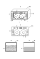
- FIG. 5 shows an example of a dehydrogenation device for reducing diffusible hydrogen in the steel by applying vibration to the steel sheet coil C by the vibration adding device 60 .
- FIG. 5A is a perspective view of the dehydrogenation device 300a. Note that FIG. 5A shows only the electromagnets 63 in the frontmost rows viewed from the side a of the dehydrogenation device 300a.
- FIG. 5B is a diagram of the dehydrogenation device 300a viewed from the side a. As shown in FIGS.
- the dehydrogenation device 300a includes a housing portion 80 for housing the steel sheet coil C, and the steel sheet coil C housed in the housing portion 80 is , with an electromagnet 63 for adding vibration.
- the number and arrangement of the electromagnets 63 are not particularly limited, but in the example of FIG. Although not shown in FIGS. 5A to 5D, each electromagnet 63 is coupled with an amplifier 62, a power supply 65, and a controller 61. Further, the controller 61 A detector 64 is coupled, and vibration is applied to the steel coil C from the electromagnet 63 .
- the steel plate coil C can be uniformly vibrated.
- the vibration propagates toward the inner circumference of the coil through the air existing between the steel sheets in the steel sheet coil C, or the vibration of the outermost circumference surface of the coil directly causes the coil to vibrate. It is considered that the vibration propagates toward the inner periphery and finally propagates to the innermost part of the coil.
- the accommodation portion 80 may accommodate a plurality of steel plate coils C. As shown in FIG.
- FIG. 5(C) shows an example of the dehydrogenation apparatus viewed from the side b.
- the electromagnets 63 may be provided at uniform intervals along the height direction and width direction of the side surface b.
- FIG. 5(D) shows a view of another example of the dehydrogenation device viewed from the side b.
- the electromagnet 63 is sufficient as long as it can apply vibration to the steel plate coil C, and may have a rectangular tubular shape with a rectangular cross section, as shown in FIG. 5(D), for example. Alternatively, an electromagnet 63 may be inserted in the hollow portion defined by the steel plate coil C to apply vibration from the inside of the steel plate coil C.
- FIG. 5(D) the electromagnet 63 may be inserted in the hollow portion defined by the steel plate coil C to apply vibration from the inside of the steel plate coil C.
- a coil holder 90 is appropriately provided inside the dehydrogenation device 300a.
- the coil holding portion 90 is not particularly limited, when the steel plate coil C is placed so that the winding axial direction of the steel plate coil C is parallel to the floor of the dehydrogenation device 300a, the coil holding portion 90 is configured as shown in FIG. As shown in (A), in order to prevent the steel sheet coil C from rolling within the dehydrogenation device 300a, it may be a pair of rod-shaped members that sandwich the steel sheet coil C from both sides.
- the coil holding part 90 may be a pair of rod-shaped members having concave arcuate upper surfaces along the arc drawn by the outermost periphery of the steel sheet coil C, as shown in FIG. 5(A). Further, although not shown, the steel sheet coil C may be placed so that the winding axis direction is parallel to the floor of the dehydrogenation device 300a.
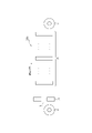
- FIG. 6 shows an example of a dehydrogenation device for reducing diffusible hydrogen in steel by applying vibration to the steel sheet coil C with a vibration adding device 70 .
- 6 is a view of the dehydrogenation device 300a as viewed from the end face side of the steel sheet coil C.
- the dehydrogenation device 300 a includes a housing portion 80 for housing the steel plate coil C, and a vibrator 72 that applies vibration to the steel plate coil C housed in the housing portion 80 .
- the vibrator 72 contacts the steel plate coil C and applies vibration to the steel plate coil C.
- each vibrator 72 is coupled with a controller 71 and a vibration detector 73, and vibration is applied from the vibrator 72 to the steel plate coil C. It has become so.
- the dehydrogenation device 300a in which vibration is applied by the vibration adding device 70 as shown in FIG. It is arranged along the surface of the coil C.
- the configuration for arranging the vibrator 72 along the surface of the steel coil C in the dehydrogenation device 300a is not particularly limited. vibrators 72 can be fixed at regular intervals.
- the vibrators 72 are provided at regular intervals along the plate width direction of the steel plate coil C.
- FIG. 4B it is preferable to use a vibrator 72 extending along the width direction of the steel sheet coil C.
- a coil holder 90 is appropriately provided inside the dehydrogenation device 300a. Since the details of the coil holding portion 90 have been described above, the description thereof is omitted here.
- the frequency of vibration of the steel sheet coil C is 100 Hz or more. If the frequency is less than 100 Hz, the effect of desorbing hydrogen contained in the cold-rolled steel sheet S cannot be obtained. From this point of view, the frequency is 100 Hz or higher, preferably 500 Hz or higher, and more preferably 1000 Hz or higher. In addition, the steel plate coil C vibrates unintentionally. However, in these vibrations, the frequency of vibration of the steel plate coil C is at most about 20 Hz, and in this case, the effect of desorbing hydrogen contained in the steel plate coil C cannot be obtained.
- the frequency of vibration of the steel plate coil C can be measured by the vibration detector 64 shown in FIG. 1 or the vibration detector 73 shown in FIG. 4A.
- the frequency of vibration of the steel plate coil C can be adjusted by controlling the frequency of the DC pulse current or the frequency of the AC continuous current. 2 can be adjusted by controlling the vibration frequency of the vibrator 72 .
- the maximum amplitude of the steel sheet coil C is 10 nm or more, preferably 100 nm or more, and more preferably 500 nm or more. Further, when the maximum amplitude of the steel plate coil C exceeds 500 ⁇ m, the strain on the steel plate surface increases, plastic deformation occurs, and as a result, hydrogen is trapped, so the hydrogen contained in the steel plate coil C is desorbed. No effect.
- the maximum amplitude of the steel sheet coil C is 500 ⁇ m or less, preferably 400 ⁇ m or less, and more preferably 300 ⁇ m or less.
- the steel sheet coil C naturally vibrates during the threading process, or receives gas from the gas wiping device 32, for example, and vibrates. However, in these vibrations, the maximum amplitude of the steel sheet coil C exceeds at least 0.5 mm, so the effect of desorbing the hydrogen contained in the steel sheet coil C cannot be obtained.
- the maximum amplitude of the steel plate coil C can be measured by the vibration detector 64 shown in FIG. 1 or the vibration detector 73 shown in FIG. 4A.
- the maximum amplitude of the steel plate coil C can be adjusted by controlling the amount of current flowing through the electromagnet 63 in the case of the vibration adding device 60 shown in FIG. , can be adjusted by controlling the amplitude of the oscillation of the oscillator 72 .
- the time for applying vibration to the steel plate coil C is not particularly limited.
- the vibration is applied without restrictions on the irradiation time. can do. Since it is presumed that the longer the vibration is applied, the more diffusible hydrogen can be reduced, the vibration is preferably applied for 1 minute or more.
- the application time of vibration is more preferably 30 minutes or longer, more preferably 60 minutes or longer.
- the vibration application time is preferably 30000 minutes or less, more preferably 10000 minutes or less, and even more preferably 1000 minutes or less.
- the vibration application time can be controlled, for example, by controlling the drive time of the vibration application device 60 by the control unit.
- the dehydrogenation device 300a may further include a heating unit for heating the steel sheet coil C and applying vibration thereto.
- the temperature of the steel sheet coil C in the vibration adding step is not particularly limited. This is because, according to this embodiment, the diffusible hydrogen in the steel can be reduced without heating and holding the steel sheet coil C. However, by adding vibration while heating the steel sheet coil C by the heating unit, the diffusion rate of hydrogen can be further increased, so that the amount of diffusible hydrogen in the steel can be further reduced. Therefore, the temperature of the steel sheet coil C when applying vibration is preferably 30° C. or higher, more preferably 50° C. or higher, and even more preferably 100° C. or higher.
- the upper limit of the temperature of the steel sheet coil C in the vibration application step is not particularly limited, but from the viewpoint of suitably preventing structural changes in the steel sheet coil C, it is set to 300° C. or less, except when vibration is applied during batch annealing, as described later. It is preferable to In this embodiment, the temperature of the steel sheet coil C when applying vibration is based on the temperature at the half position in the radial direction of the steel sheet coil. The temperature at the 1/2 position of the steel plate coil in the radial direction is measured by directly inserting a thermocouple at the 1/2 position of the steel plate coil in the radial direction and measuring the temperature of the steel strip present at the 1/2 position in the radial direction. can.
- the method of heating the steel plate coil C is, for example, a method of installing a heater on the side wall of the housing portion, a method of blowing high temperature air generated outside to the housing portion 80, and a method of circulating in the housing portion. I don't mind.
- the dehydrogenation device 300a may further have a damping section that prevents the vibration from being transmitted to the outside of the dehydrogenation device 300a.
- the damping portion may be, for example, a damping material provided to surround the inner wall of the housing portion 80 .
- the amount of diffusible hydrogen in the product coil C obtained after applying vibration can be reduced to 0.5 mass ppm or less.
- the amount of diffusible hydrogen in the steel after applying vibration is preferably 0.3 ppm by mass or less, more preferably 0.2 ppm by mass or less.
- the amount of diffusible hydrogen in product coil C is measured as follows. A test piece having a length of 30 mm and a width of 5 mm is taken from a half position of the product coil in the radial direction. When the steel sheet is a hot-dip galvanized steel sheet or an alloyed hot-dip galvanized steel sheet, the hot-dip galvanized layer or the alloyed hot-dip galvanized layer of the test piece is removed by grinding or alkali. After that, the amount of hydrogen released from the test piece is measured by thermal desorption spectrometry (TDS). Specifically, after continuously heating from room temperature to 300 ° C. at a temperature increase rate of 200 ° C./h, cooling to room temperature, measuring the cumulative amount of hydrogen released from the test piece from room temperature to 210 ° C., The amount of diffusible hydrogen in coil C is assumed.
- TDS thermal desorption spectrometry
- the dehydrogenation apparatus 300a and the steel sheet manufacturing method according to the present embodiment can be applied to the manufacture of hot-rolled steel sheets.
- a steel sheet manufacturing system includes a hot rolling apparatus that hot-rolls a steel slab to obtain a hot-rolled steel sheet, and a hot-rolled steel sheet winding apparatus that winds the hot-rolled steel sheet to obtain a hot-rolled coil. and a steel sheet dehydrogenation apparatus using the hot rolled coil as the steel sheet coil C.
- the hot rolling apparatus performs hot rolling including rough rolling and finish rolling on a steel slab having a known chemical composition to obtain a hot rolled steel sheet.
- the hot-rolled steel sheet winding device winds the hot-rolled steel sheet into a hot-rolled coil.
- the dehydrogenation apparatus 300a uses the hot-rolled coil as the steel sheet coil C and applies vibration to the hot-rolled coil under the conditions described above.
- the vibration By applying the vibration, the amount of diffusible hydrogen in the steel is reduced, and a hot-rolled steel sheet having excellent resistance to hydrogen embrittlement can be obtained.
- the obtained hot-rolled steel sheet may be further subjected to cold rolling to obtain a cold-rolled steel sheet.
- a method for manufacturing a steel sheet according to this application example includes the steps of: hot-rolling a steel slab to obtain a hot-rolled steel sheet; and winding the hot-rolled steel sheet to obtain a hot-rolled coil.
- Let the coil be the steel plate coil.
- the method of manufacturing the hot-rolled coil before applying vibration is not particularly limited. may be wound according to a known method to form a hot-rolled coil. By applying vibration to the hot-rolled coil under the conditions described above, it is possible to reduce the amount of diffusible hydrogen in the steel and obtain a hot-rolled steel sheet with excellent resistance to hydrogen embrittlement.
- the obtained hot-rolled steel sheet may be further subjected to cold rolling to obtain a cold-rolled steel sheet.
- the dehydrogenation apparatus 300a and the steel sheet manufacturing method according to the present embodiment can also be applied to the manufacture of cold-rolled steel sheets.
- a steel sheet manufacturing system includes a cold rolling apparatus that cold-rolls a hot-rolled steel sheet to obtain a cold-rolled steel sheet, and a cold-rolled steel sheet winding machine that winds the cold-rolled steel sheet to obtain a cold-rolled coil. and a dehydrogenation device 300a that uses the cold-rolled coil as the steel sheet coil C.
- the cold rolling apparatus applies or does not perform hot-rolled steel sheet annealing on a known hot-rolled steel sheet, and performs one cold rolling on the hot-rolled steel sheet after hot rolling or the hot-rolled steel sheet after hot-rolled sheet annealing.
- a cold-rolled steel sheet having a final thickness is obtained by cold rolling two or more times with rolling or intermediate annealing.
- the cold-rolled steel sheet winding device winds the cold-rolled steel sheet after cold rolling according to a known method to form a cold-rolled coil.
- the dehydrogenation apparatus 300a uses the cold-rolled coil as the steel sheet coil C and applies vibration to the cold-rolled coil under the conditions described above. By applying the vibration, the amount of diffusible hydrogen in the steel can be reduced, and a cold-rolled steel sheet with excellent resistance to hydrogen embrittlement can be obtained.
- the steel sheet manufacturing system may further include a dehydrogenation device 300a capable of applying vibration under the conditions described above to the hot-rolled coil obtained by winding the hot-rolled steel sheet after hot rolling. .
- the hot-rolled steel sheet is taken out from the hot-rolled coil to which the vibration has been applied and is cold-rolled to form a cold-rolled coil. It is possible to obtain a steel sheet having a particularly excellent resistance to hydrogen embrittlement by further reducing the amount of toxic hydrogen.
- a steel sheet manufacturing method includes a step of cold-rolling a hot-rolled steel sheet to obtain a cold-rolled steel sheet, and a step of winding the cold-rolled steel sheet to obtain a cold-rolled coil.
- Let the coil be the steel plate coil.
- the manufacturing method of the cold-rolled coil before applying vibration is not particularly limited.
- a steel slab having a known chemical composition is hot-rolled by rough rolling and finish rolling to form a hot-rolled steel sheet, and the hot-rolled steel sheet is subjected to hot-rolled sheet annealing or not,
- a cold-rolled steel sheet having a final thickness obtained by subjecting a hot-rolled steel sheet after hot rolling or a hot-rolled steel sheet after hot-rolled sheet annealing to cold rolling once or cold rolling two or more times with intermediate annealing between them. can do.
- the cold-rolled steel sheet after cold rolling is wound into a cold-rolled coil according to a known method.
- the hot-rolled steel sheet after hot rolling is wound to form a hot-rolled coil, and the hot-rolled coil is also subjected to vibration under the conditions described above. may Next, the hot-rolled steel sheet is taken out from the hot-rolled coil to which vibration has been applied, cold-rolled to form a cold-rolled coil, and further vibration is applied to the cold-rolled coil to reduce the amount of diffusible hydrogen in the steel. By further reducing it, a steel sheet having particularly excellent resistance to hydrogen embrittlement can be obtained.
- the type of hot-rolled steel sheet or cold-rolled steel sheet to which vibration is applied is not particularly limited.
- the chemical composition of the steel sheet is not particularly limited, steel sheets having the following chemical composition are exemplified as steel sheets to which the embodiments can be particularly suitably applied. First, the appropriate range of the chemical composition of the steel sheet and the reason for its limitation will be described.
- [Essential ingredient] C 0.030% or more and 0.800% or less C is an element necessary for increasing the strength. By making the amount of C 0.030% or more, particularly suitable strength can be obtained. Also, by setting the C content to 0.800% or less, embrittlement of the material itself can be particularly preferably prevented. From this point of view, the C content is preferably 0.030% or more and preferably 0.800% or less. The amount of C is more preferably 0.080% or more. Moreover, the amount of C is more preferably 0.500% or less.
- Si 0.01% or more and 3.00% or less
- Si is a solid-solution-strengthening element that becomes a substitution-type solid solution and greatly hardens the material, and is effective in increasing the strength of the steel sheet.
- the amount of Si is preferably 0.01% or more.
- the Si content is preferably 0.01% or more, and preferably 3.00% or less.
- Si is more preferably 0.10% or more, and more preferably 2.50% or less.
- Mn 0.01% or more and 10.00% or less Mn increases the strength of the steel sheet by solid-solution strengthening.
- the Mn content is preferably 0.01% or more.
- the Mn content is preferably 10.00% or less.
- the Mn content is more preferably 0.5% or more, and more preferably 8.00% or less.
- P 0.001% or more and 0.100% or less
- P is an element that has a solid-solution strengthening action and can be added according to the desired strength.
- the amount of P is set to 0.100% or less.
- the P content is preferably 0.001% or more and preferably 0.100% or less. More preferably, the amount of P is 0.003% or more.
- the S content is preferably 0.0200% or less, more preferably 0.0100% or less, and even more preferably 0.0050% or less.
- the lower limit of the S content is not particularly limited, the S content is preferably 0.0001% or more, more preferably 0.0050% or less, due to production technology restrictions.
- the N content is preferably 0.0100% or less, more preferably 0.0070% or less.
- the lower limit of the N content is not particularly limited, the N content is preferably 0.0005% or more, more preferably 0.0010% or more, due to production technology restrictions.
- Al 2.000% or less
- Al is an element that acts as a deoxidizing agent and is effective in improving the cleanliness of steel, and is preferably added in the deoxidizing process.
- the amount of Al is preferably 0.001% or more.
- the Al content is preferably 2.000% or less from the viewpoint of suitably preventing the occurrence of billet cracking during continuous casting. More preferably, the amount of Al is 0.010% or more. Moreover, it is more preferable that the amount of Al is 1.200% or less.
- the component composition is further expressed in mass %, Ti: 0.200% or less, Nb: 0.200% or less, V: 0.500% or less, W: 0.500% or less, B: 0.0050% or less, Ni : 1.000% or less, Cr: 1.000% or less, Mo: 1.000% or less, Cu: 1.000% or less, Sn: 0.200% or less, Sb: 0.200% or less, Ta: 0 At least one element selected from the group consisting of .100% or less, Ca: 0.0050% or less, Mg: 0.0050% or less, Zr: 0.0050% or less, and REM: 0.0050% or less You may
- Ti 0.200% or less Ti contributes to an increase in the strength of the steel sheet by precipitation strengthening of the steel and fine grain strengthening by suppressing the growth of ferrite crystal grains.
- Ti When Ti is added, it is preferably 0.005% or more.
- the amount of Ti When adding Ti, the amount of Ti is more preferably 0.010% or more. Also, by setting the Ti amount to 0.200% or less, precipitation of carbonitrides can be suitably prevented, and formability can be further improved. Therefore, when Ti is added, it is preferable that the amount added is 0.200% or less.
- the amount of Ti is more preferably 0.100% or less.
- Nb 0.200% or less
- V 0.500% or less
- W 0.500% or less
- Nb, V, and W are effective for precipitation strengthening of steel.
- each of them is preferably 0.005% or more.
- each content is more preferably 0.010% or more.
- Nb is added, the amount added is preferably 0.200% or less, more preferably 0.100% or less.
- V and W the amount added is preferably 0.500% or less, more preferably 0.300% or less.
- B 0.0050% or less B is effective for strengthening grain boundaries and increasing the strength of steel sheets.
- B is preferably 0.0003% or more.
- B is preferably 0.0050% or less. Therefore, when B is added, the amount added is preferably 0.0050% or less, more preferably 0.0030% or less.
- Ni 1.000% or less
- Ni is an element that increases the strength of steel through solid-solution strengthening. When Ni is added, it is preferably 0.005% or more. From the viewpoint of further improving ductility by reducing the area ratio of hard martensite, Ni is preferably 1.000% or less. Therefore, when Ni is added, the amount added is preferably 1.000% or less, more preferably 0.500% or less.
- Cr: 1.000% or less, Mo: 1.000% or less Cr and Mo have the effect of improving the balance between strength and moldability, and can be added as necessary.
- Cr and Mo it is preferable that Cr: 0.005% or more and Mo: 0.005% or more.
- Cr and Mo are preferably Cr: 1.000% or less and Mo: 1.000% or less, respectively.
- Cr and Mo are preferably Cr: 0.500% or less and Mo: 0.500% or less, respectively.
- Cu 1.000% or less
- Cu is an element effective in strengthening steel and can be added as necessary.
- it is preferably 0.005% or more.
- the amount is preferably 1.000% or less, and 0.200% or less. is more preferable.
- Sn 0.200% or less
- Sb 0.200% or less
- Sn and Sb suppress decarburization of a region of about several tens of ⁇ m on the surface of the steel sheet caused by nitridation and oxidation of the steel sheet surface. Adding it is effective in ensuring strength and material stability.
- each content is 0.002% or more.
- Sn and Sb are added in order to obtain better toughness, their contents are preferably 0.200% or less, more preferably 0.050% or less.
- Ta 0.100% or less Ta, like Ti and Nb, forms alloy carbides and alloy carbonitrides and contributes to high strength. In addition, it partially dissolves in Nb carbides and Nb carbonitrides and forms composite precipitates such as (Nb, Ta) (C, N), thereby significantly suppressing coarsening of precipitates and precipitation strengthening. It is considered that there is an effect of stabilizing the contribution to strength by Therefore, it is preferable to contain Ta.
- Ta when Ta is added, it is preferably 0.001% or more.
- the upper limit of the amount of Ta is not particularly limited, but from the viewpoint of cost reduction, when Ta is added, the content is preferably 0.100% or less, and preferably 0.050% or less. more preferred.
- Ca 0.0050% or less
- Mg 0.0050% or less
- Zr 0.0050% or less
- REM 0.0050% or less
- the amount of each added should be 0.0050% or less. is preferred, and 0.0020% or less is more preferred.
- the present embodiment can also be suitably applied to high-strength steel sheets in which hydrogen embrittlement is particularly problematic.
- vibration By applying vibration to the steel sheet coil C made of high-strength steel sheet in the dehydrogenation device 300a or by applying the manufacturing method of the present steel sheet, the amount of diffusible hydrogen in the steel is reduced, and hydrogen resistance
- a high-strength steel sheet with excellent embrittlement properties can be obtained.
- the steel sheet produced in this embodiment can be a high-strength steel sheet having a tensile strength of 590 MPa or higher, more preferably 1180 MPa or higher, and even more preferably 1470 MPa or higher.
- the tensile strength of the steel sheet is measured according to JIS Z 2241 (2011).
- [Essential ingredient] C 0.001% or more and 0.400% or less C is an essential element for obtaining high strength in stainless steel.
- the C content exceeds 0.400%, it combines with Cr during tempering in steel production and precipitates as carbides, which deteriorate the corrosion resistance and toughness of the steel.
- the content of C is set to 0.001% or more and 0.400% or less.
- the C content is preferably 0.005% or more. Also, the C content is preferably 0.350% or less.
- Si 0.01% to 2.00% Si is an element useful as a deoxidizing agent. This effect is obtained by setting the Si content to 0.01% or more. However, when Si is contained excessively, the Si dissolved in the steel reduces the workability of the steel. Therefore, the upper limit of the Si content is set to 2.00%.
- the Si content is preferably 0.05% or more. Also, the Si content is preferably 1.8% or less.
- Mn 0.01% to 5.00% Mn has the effect of increasing the strength of steel. These effects are obtained with a Mn content of 0.01% or more. However, when the Mn content exceeds 5.00%, the workability of the steel deteriorates. Therefore, the upper limit of the Mn content is set to 5.00%.
- the Mn content is preferably 0.05% or more. Also, the Mn content is preferably 4.6% or less.
- P 0.001% or more and 0.100% or less
- P is an element that promotes grain boundary fracture due to grain boundary segregation, so the lower the better, the upper limit is made 0.100%.
- the P content is 0.030% or less. More preferably, the P content is 0.020% or less.
- the lower limit of the P content is not particularly limited, it should be 0.001% or more from the viewpoint of production technology.
- S 0.0001% or more and 0.0200% or less
- S is an element that exists as sulfide-based inclusions such as MnS and reduces ductility, corrosion resistance, etc. Especially when the content exceeds 0.0200% These adverse effects are noticeable in some cases. Therefore, it is desirable that the S content be as low as possible, and the upper limit of the S content is 0.0200%.
- the S content is 0.010% or less. More preferably, the S content is 0.005% or less.
- the lower limit of the S content is not particularly limited, it should be 0.0001% or more from the viewpoint of production technology.
- Cr 9.0% or more and 28.0% or less
- Cr is a basic element that constitutes stainless steel and is also an important element that develops corrosion resistance.
- the Cr content is set to 9.0% or more and 28.0% or less.
- the Cr content is preferably 10.0% or more.
- the Cr content is preferably 25.0% or less.
- Ni 0.01% to 40.0%
- Ni is an element that improves the corrosion resistance of stainless steel. hardens, deteriorating formability and easily causing stress corrosion cracking. Therefore, the Ni content is set to 0.01% or more and 40.0% or less. The Ni content is preferably 0.1% or more. Also, the Ni content is preferably 30.0% or less.
- N 0.0005% or more and 0.500% or less N is an element harmful to improving the corrosion resistance of stainless steel, but it is also an austenite forming element. If the content exceeds 0.5%, Ni precipitates as nitrides during heat treatment, degrading the corrosion resistance and toughness of the stainless steel. Therefore, the upper limit of the N content is made 0.500%, preferably 0.20%.
- Al 3.000% or less
- Al is added as a deoxidizing element and has the effect of suppressing the peeling of oxide scale.
- adding more than 3.000% results in reduced elongation and deteriorated surface quality. Therefore, the upper limit of the Al content is set to 3.000%.
- the lower limit of the Al content is not particularly limited, it is preferably 0.001% or more. More preferably, the Al content is 0.01% or more. Also, the Al content is preferably 2.5% or less.
- the composition of the stainless steel is, in mass%, Ti: 0.500% or less, Nb: 0.500% or less, V: 0.500% or less, W: 2.000% or less, B: 0.0050%.
- Mo 2.000% or less
- Cu 3.000% or less
- Sn 0.500% or less
- Sb 0.200% or less
- Ta 0.100% or less
- Ca 0.0050% or less
- It may further contain at least one element selected from the group consisting of Mg: 0.0050% or less, Zr: 0.0050% or less, and REM: 0.0050% or less.
- Ti 0.500% or less Ti is an element added to bond with C, N, and S to improve corrosion resistance, intergranular corrosion resistance, and deep drawability. However, if it is added in excess of 0.500%, solid solution Ti hardens the stainless steel and deteriorates toughness. Therefore, the upper limit of the Ti content is set to 0.500%. Although the lower limit of the Ti content is not particularly limited, it is preferably 0.003% or more. More preferably, the Ti content is 0.005% or more. Also, the Ti content is preferably 0.300% or less.
- Nb 0.500% or less
- Nb is an element added to bond with C, N, and S to improve corrosion resistance, intergranular corrosion resistance, and deep drawability. In addition to improving workability and high-temperature strength, it is added as necessary to suppress crevice corrosion and promote re-passivation. However, excessive addition of Nb hardens the stainless steel and degrades formability, so the upper limit of the Nb content is made 0.500%.
- the lower limit of the Nb content is not particularly limited, it is preferably 0.003% or more. More preferably, the Nb content is 0.005% or more. Also, the Nb content is preferably 0.300% or less.
- V 0.500% or less V is added as necessary to suppress crevice corrosion. However, excessive addition hardens the stainless steel and degrades formability, so the upper limit of the V content is made 0.500%.
- the lower limit of the V content is not particularly limited, the V content is preferably 0.01% or more, and more preferably 0.03% or more. Also, the V content is preferably 0.300% or less.
- W 2.000% or less W contributes to improvement of corrosion resistance and high-temperature strength, so it is added as necessary. However, the addition of more than 2.000% hardens the stainless steel, leading to deterioration in toughness and cost increase during steel plate production, so the upper limit of the W content is made 2.000%.
- the lower limit of the W content is not particularly limited, it is preferably 0.050% or more. More preferably, the W content is 0.010% or more. Also, the W content is preferably 1.500% or less.
- B 0.0050% or less
- the lower limit of the B content is not particularly limited, it is preferably 0.0002% or more. More preferably, the B content is 0.0005% or more. Also, the B content is preferably 0.0035% or less.
- Mo 2.000% or less
- Mo is an element that improves corrosion resistance, and is an element that suppresses crevice corrosion particularly when the steel has a crevice structure.
- the upper limit of the content is made 2.000%.
- the lower limit of the Mo content is not particularly limited, it is preferably 0.005% or more. More preferably, the Mo content is 0.010% or more. Also, the Mo content is preferably 1.500% or less.
- Cu 3.000% or less
- Cu like Ni and Mn, is an austenite-stabilizing element and is effective for grain refinement by phase transformation. Further, it is added as necessary in order to suppress crevice corrosion and promote re-passivation. However, excessive addition of Ni causes hardening and deteriorates toughness and formability, so the upper limit of the content is made 3.000%.
- the lower limit of the Cu content is not particularly limited, it is preferably 0.005% or more. More preferably, the Cu content is 0.010% or more. Also, the Cu content is preferably 2.000% or less.
- Sn 0.500% or less Sn contributes to the improvement of corrosion resistance and high-temperature strength, so it is added as necessary. However, if added in excess of 0.500%, slab cracking may occur during steel sheet production, so the upper limit of the content is made 0.500% or less.
- the lower limit of the Sn content is not particularly limited, it is preferably 0.002% or more. More preferably, the Sn content is 0.005% or more. Also, the Sn content is preferably 0.300% or less.
- Sb 0.200% or less
- Sb is an element that segregates at grain boundaries to increase high-temperature strength. However, if it exceeds 0.200%, Sb segregation occurs and cracks occur during welding, so the upper limit of the content is made 0.200%.
- the lower limit of the Sb content is not particularly limited, it is preferably 0.002% or more. More preferably, the Sb content is 0.005% or more. Also, the Sb content is preferably 0.100% or less.
- Ta 0.100% or less Ta is added as necessary because it combines with C and N and contributes to the improvement of toughness. However, if it is added in excess of 0.100%, the effect is saturated and the manufacturing cost increases, so the upper limit of the content is made 0.100%.
- the lower limit of the Ta content is not particularly limited, it is preferably 0.002% or more. More preferably, the Ta content is 0.005% or more. Also, the Ta content is preferably 0.080% or less.
- Ca 0.0050% or less
- Mg 0.0050% or less
- Zr 0.0050% or less
- REM Radar Earth Metal
- Ca, Mg, Zr and REM have a sulfide shape It is an effective element for spheroidizing and ameliorating the adverse effects of sulfides on formability.
- the content of each element is preferably 0.0005% or more.
- the content of each element should be 0.0050% or less.
- the lower limit of the content of these elements is not particularly limited, the content of each element is preferably 0.0002% or more. More preferably, the content of each element is 0.0005% or more. Also, the content of each element is preferably 0.0035% or less.
- Annealing may be performed on the cold-rolled steel sheet and the hot-rolled steel sheet described above. That is, the present steel sheet manufacturing system may have an annealing apparatus for annealing the cold-rolled steel sheet and the hot-rolled steel sheet.
- the timing of annealing is not particularly limited. It is preferable to apply
- the annealing apparatus may be a batch annealing furnace or a continuous annealing apparatus.
- the steel sheet manufacturing system includes a batch annealing furnace in which cold rolled coils or hot rolled coils are batch annealed to obtain an annealed coil, and the annealed coil is used as the steel sheet coil C. and a dehydrogenation device 300a.
- a batch annealing furnace performs batch annealing on cold-rolled coils or hot-rolled coils to obtain annealed coils.
- batch annealing means heating and holding in a batch annealing furnace, and does not include slow cooling after heating and holding.
- the annealed coil is cooled by furnace cooling or air cooling in a batch annealing furnace.
- the dehydrogenation apparatus 300a uses the steel sheet coil C as the annealing coil and applies vibration to the steel sheet coil C under the conditions described above.
- the dehydrogenation device 300a may be provided separately from the batch annealing furnace, but the storage section 80 and the heating section of the dehydrogenation device 300a may also serve as the batch annealing furnace. In other words, the dehydrogenation device 300a may be provided by providing the batch annealing furnace with the vibration adding device 60 that applies vibration to the steel sheet coil C housed in the furnace to produce a product coil.
- the vibration can be applied after the annealing coil is cooled to room temperature after the batch annealing. can also be added.
- the higher the temperature of the steel sheet the more efficiently the diffusible hydrogen can be reduced. By adding, the diffusible hydrogen in the steel can be reduced more efficiently.
- the steel sheet manufacturing method includes a process of obtaining an annealed coil by performing batch annealing on a cold-rolled coil or hot-rolled coil obtained by winding a cold-rolled steel sheet or hot-rolled steel sheet. Vibration is applied to the annealing coil under the conditions described above, with the annealing coil being the steel sheet coil.
- a cold-rolled steel sheet or hot-rolled steel sheet is coiled by a known method to form a cold-rolled coil or hot-rolled coil.
- the cold-rolled coil or hot-rolled coil is placed in a batch annealing furnace and batch-annealed in the batch annealing furnace to obtain an annealed coil.
- the annealed coil is cooled by furnace cooling or air cooling in a batch annealing furnace.
- vibration is applied to the annealing coil under the conditions described above. Vibration may be applied to the annealing coil during batch annealing, that is, while the cold-rolled coil or hot-rolled coil is being heated and held. Furthermore, vibration may be applied after batch annealing, that is, after heating and holding the cold-rolled coil or the hot-rolled coil. Vibration may be applied after the annealing coil is cooled to room temperature after batch annealing, or may be applied while the annealing coil is being cooled. As described above, the higher the temperature of the steel sheet, the more efficiently the diffusible hydrogen can be reduced. is preferred.
- Vibration can be applied to the annealing coil in the batch annealing furnace, or the annealing coil can be removed from the batch annealing furnace.
- vibration is applied to the annealing coil in the batch annealing furnace.
- Annealing can also be performed by passing the cold-rolled steel sheet or hot-rolled steel sheet through a continuous annealing line (CAL).
- CAL continuous annealing line
- the steel sheet manufacturing system includes a pre-annealing dispensing apparatus for dispensing cold-rolled steel sheets or hot-rolled steel sheets from cold-rolled coils or hot-rolled steel sheets, and the cold-rolled steel sheets or hot-rolled steel sheets.
- the pre-annealing delivery device delivers cold-rolled steel sheets or hot-rolled steel sheets from cold-rolled coils or hot-rolled coils, and supplies the cold-rolled steel sheets or hot-rolled steel sheets to CAL.
- the configuration of the CAL is not particularly limited, but in one example the CAL has a continuous annealing furnace in which a heating zone, a soaking zone, and a cooling zone are arranged in this order.
- the cooling zone may be composed of a plurality of cooling zones, in which case some of the cooling zones are holding zones that hold the cold-rolled steel strip in the cooling process within a certain temperature range, and reheating the steel strip in the cooling process. It may be a reheating zone that Further, a preheating zone may be provided on the upstream side of the heating zone in the sheet threading direction.
- the pre-annealing payoff device can be a payoff reel located upstream of the CAL continuous annealing furnace.
- the annealed steel strip winding device can be a tension reel provided downstream of the CAL continuous annealing furnace.
- CAL In CAL, (A) a cold-rolled steel sheet or hot-rolled steel sheet discharged from a cold-rolled coil or hot-rolled coil by a pay-off reel, and (B) a heating zone, a soaking zone, and a cooling zone from the upstream side in the sheet passing direction.
- the steel sheet is passed through a continuous annealing furnace located, (B-1) the cold-rolled steel sheet or hot-rolled steel sheet is annealed in the heating zone and the soaking zone to form an annealed steel sheet, and (B-2) the steel sheet is annealed in the cooling zone.
- the steel sheet is cooled and continuously annealed, (C) the annealed steel sheet discharged from the continuous annealing furnace is continuously passed, and (D) the steel sheet is wound by a tension reel to form an annealed coil.
- the dehydrogenation device 300a uses the steel sheet coil C as the annealing coil, and applies vibration to the annealing coil under the conditions described above. By applying the vibration, the amount of diffusible hydrogen in the steel can be reduced, and an annealed steel sheet with excellent resistance to hydrogen embrittlement can be obtained.
- the cooling method and cooling rate of the steel sheet in the cooling zone are not particularly limited, and any cooling such as gas jet cooling, mist cooling, and water cooling may be used.
- the steel sheet manufacturing method includes a step of discharging the cold-rolled steel sheet from the cold-rolled coil, a step of continuously annealing the cold-rolled steel sheet to obtain an annealed steel sheet, and the annealing and winding a steel sheet to obtain an annealed coil, wherein the annealed coil is used as the steel sheet coil.
- a steel sheet coil is paid out by a payoff reel, and (B) the steel sheet is passed through an annealing furnace in which a heating zone, a soaking zone, and a cooling zone are positioned from the upstream side in the sheet passing direction.
- a cold-rolled steel sheet or hot-rolled steel sheet having excellent resistance to hydrogen embrittlement can be obtained by applying vibration to the annealed coil under the conditions described above.
- a steel sheet manufacturing system includes a plating apparatus that forms a plating film on the surface of a hot-rolled steel sheet or a cold-rolled steel sheet to obtain a plated steel sheet, and a plated steel sheet that winds up the plated steel sheet to obtain a plated steel sheet coil.
- a winding device and a dehydrogenation device 300a that uses the plated steel sheet coil as the steel sheet coil C are provided.
- a plating apparatus obtains a plated steel sheet by forming a plating film on the surface of a hot-rolled steel sheet or a cold-rolled steel sheet as a base steel sheet.
- the plated steel sheet winding device winds the plated steel sheet into a plated steel sheet coil.
- the dehydrogenation device 300a uses the plated steel sheet coil as the steel sheet coil C, and applies vibration to the plated steel sheet coil under the conditions described above. By applying the vibration, the amount of diffusible hydrogen in the steel can be reduced, and a plated steel sheet having excellent resistance to hydrogen embrittlement can be obtained.
- a hot-rolled steel sheet or a cold-rolled steel sheet may be used as a base steel sheet, a plating film may be formed on the surface to obtain a plated steel sheet, and the plated steel sheet may be used as a steel sheet coil to which vibration is added.
- the method of manufacturing the steel sheet includes the steps of forming a plating film on the surface of a hot-rolled steel sheet or a cold-rolled steel sheet to obtain a plated steel sheet, winding the plated steel sheet, and plating the steel sheet. and obtaining a steel sheet coil, wherein the plated steel sheet coil is used as the steel sheet coil.
- the type of plating equipment is not particularly limited, it may be, for example, a hot-dip galvanizing equipment.
- the hot-dip galvanizing equipment can be a continuous hot-dip galvanizing line (CGL) in one example.
- the configuration of the CGL is not particularly limited, but in one example, the CGL has a continuous annealing furnace in which a heating zone, a soaking zone, and a cooling zone are arranged in this order, and a hot-dip galvanizing facility provided after the cooling zone.
- a hot-rolled steel sheet or cold-rolled steel sheet is annealed in a reducing atmosphere containing hydrogen in a soaking zone to obtain an annealed steel sheet, and (B-2) ) cooling the annealed steel sheet in the cooling zone, performing continuous annealing, (C) continuing to thread the annealed steel sheet discharged from the annealing furnace, and (C-1) located downstream of the continuous annealing furnace in the sheet threading direction
- the annealed steel sheet is immersed in a hot dip galvanizing bath, the annealed steel sheet is hot dip galvanized to form a hot dip galvanized steel sheet, and (D) the hot dip galvanized steel sheet is wound up by a tension reel to form a hot dip galvanized steel sheet coil.
- the dehydrogenation device 300a uses the hot-dip galvanized steel sheet coil as the steel sheet coil C, and applies vibration to the hot-dip galvanized steel sheet coil under the conditions described above. By applying the vibration, the amount of diffusible hydrogen in the steel can be reduced, and a hot-dip galvanized steel sheet with excellent resistance to hydrogen embrittlement can be obtained.
- the method of forming the plating film on the surface of the hot-rolled steel sheet or cold-rolled steel sheet is not particularly limited, but the plating process may include a hot-dip galvanizing process. That is, a hot-rolled steel sheet or a cold-rolled steel sheet may be hot-dip galvanized to form a hot-dip galvanized steel sheet. In one example, a continuous hot-dip galvanizing line (CGL) can be used to hot-dip galvanize a steel sheet.
- CGL continuous hot-dip galvanizing line
- a steel sheet coil is (A) discharged by a pay-off reel, and (B) a hot-rolled steel sheet or a cold-rolled steel sheet is placed in an annealing furnace in which a heating zone, a soaking zone, and a cooling zone are positioned from the upstream side in the sheet passing direction.
- B-1 In the soaking zone, the hot-rolled steel sheet or cold-rolled steel sheet is annealed in a reducing atmosphere containing hydrogen to form an annealed steel sheet
- B-2) in the cooling zone the annealed steel sheet is cooled.
- step (C) includes a step of immersing the annealed steel sheet in a hot dip galvanizing bath located downstream of the annealing furnace in the sheet running direction to subject the annealed steel sheet to a hot dip galvanizing treatment.
- the wound annealed coil is a hot-dip galvanized steel sheet coil.
- the plating equipment may include a hot-dip galvanizing equipment followed by an alloying furnace.
- a hot-dip galvanizing equipment followed by an alloying furnace.
- the steel sheet is placed in an alloying furnace located downstream of the hot-dip galvanizing bath in the sheet passing direction. is passed through the plate, and the hot-dip galvanization is heated and alloyed.
- the alloyed hot-dip galvanized steel sheet that has been passed through an alloying furnace and alloyed is wound up into an alloyed hot-dip galvanized steel sheet coil.
- the dehydrogenation device 300a uses the alloyed hot-dip galvanized steel sheet coil as the steel sheet coil C, and applies vibration to the alloyed hot-dip galvanized steel sheet coil under the conditions described above. By applying the vibration, an alloyed hot-dip galvanized steel sheet having excellent resistance to hydrogen embrittlement can be obtained.
- the plating process may include a hot-dip galvanizing process followed by an alloying process. That is, the hot-dip galvanized steel sheet may be subjected to further alloying treatment to obtain an alloyed hot-dip galvanized steel sheet, and vibration may be applied to the hot-dip galvanized steel sheet.
- the steel sheet is placed in an alloying furnace located downstream of the hot-dip galvanizing bath in the sheet passing direction. is passed through the plate, and the hot-dip galvanization is heated and alloyed.
- the alloyed hot-dip galvanized steel sheet that has been passed through an alloying furnace and alloyed is wound up into an alloyed hot-dip galvanized steel sheet coil.
- vibration to the galvannealed steel sheet coil under the conditions described above a galvannealed steel sheet having excellent resistance to hydrogen embrittlement can be obtained.
- the plating apparatus can form Al plating films and Fe plating films in addition to zinc plating films.
- the plating apparatus is not limited to a hot dip plating apparatus, and may be an electroplating apparatus.
- the type of plating film that can be formed on the surface of the steel sheet to which vibration is applied is not particularly limited, and may be an Al plating film or an Fe plating film.
- the method of forming the plated film is not limited to the hot dip plating process, and may be an electroplating process.
- the steel sheet manufacturing system corrects the shape and corrects the surface roughness of the hot-rolled steel sheet, the cold-rolled steel sheet obtained as described above, and the plated steel sheet having various plating films on the surface of the hot-rolled steel sheet or cold-rolled steel sheet. It may further have a skin-pass rolling device that performs skin-pass rolling for the purpose of adjustment or the like. That is, in the steel sheet manufacturing method of the present invention, the hot-rolled steel sheet, the cold-rolled steel sheet obtained as described above, and the plated steel sheet having various plating films on the surface of the hot-rolled steel sheet or cold-rolled steel sheet are subjected to shape correction. And skin pass rolling can be performed for the purpose of adjusting the surface roughness.
- the rolling reduction of skin pass rolling is preferably controlled to 0.1% or more, and is preferably controlled to 2.0% or less.
- the skin-pass rolling apparatus may be an apparatus continuous with CGL or CAL (in-line), or may be an apparatus discontinuous with CGL or CAL (off-line).
- the skin-pass rolling may be performed at once with the target rolling reduction, or the skin-pass rolling may be performed in several steps to achieve the target rolling reduction.
- the steel sheet manufacturing system includes the hot-rolled steel sheet, the cold-rolled steel sheet obtained as described above, and the surface of the hot-rolled steel sheet or the plated steel sheet having various plating films on the surface of the cold-rolled steel sheet. It may further have a coating facility for performing various coating treatments. That is, the surface of the hot-rolled steel sheet, the cold-rolled steel sheet obtained as described above, and the plated steel sheet having various plating films on the surface of the hot-rolled steel sheet or cold-rolled steel sheet are subjected to various coating treatments such as resin or oil coating. can also
- a dehydrogenation apparatus includes a dispensing device for dispensing a steel strip from a steel plate coil, a threading device for threading the steel strip, a winding device for winding the steel strip, and the threading device.
- a vibration applying device for applying vibration to the steel strip being passed through a plate device so that the vibration frequency of the steel strip is 100 to 100000 Hz and the maximum amplitude of the steel strip is 10 nm to 500 ⁇ m. and have
- a method for manufacturing a steel sheet according to Embodiment 2 of the present invention includes a step of unloading a steel strip from a steel plate coil, a threading step of threading the steel strip, and winding the steel strip into a product coil. and the step of vibrating the steel strip such that the vibration frequency of the steel strip is 100 to 100000 Hz and the maximum amplitude of the steel strip is 10 nm to 500 ⁇ m. includes a vibration adding step of adding
- a steel sheet optionally annealed after hot rolling or cold rolling, or a plated steel sheet further coated with a plating film is coiled into a steel sheet coil. Since the mass of the steel coil is often different from the shipping packaging mass, a division into packaging masses takes place in the recoil line.
- a steel strip is discharged from a steel sheet coil by a discharging device, and the discharged steel strip is rewound by a rewinding device, and sheared and divided when it reaches a predetermined packing mass.
- vibration is applied to the discharged steel strip by this recoil line. According to this embodiment, since vibration is applied to the steel strip being threaded, the vibration can be applied evenly over the entire length of the steel strip.
- the dehydrogenation apparatus is a discontinuous apparatus (offline) from the continuous annealing apparatus or the continuous hot-dip galvanizing apparatus, and the dehydrogenation apparatus performs annealing, plating, and hot-dip galvanizing on the steel strip. Does not include equipment for processing.
- vibration adding device 60 A vibration applying device can be used to apply the vibration.
- the vibration adding device is configured such that the steel strip being threaded vibrates due to an external force (attractive force) applied to the steel strip being threaded by the electromagnet 63, similar to the vibration adding device 60 according to the first embodiment described above.
- the configuration of the vibration applying device 60 can be the same as that of the first embodiment, except that the object to which vibration is applied is not the steel plate coil but the steel strip being threaded.
- the electromagnet 63 it is sufficient to provide the electromagnet 63 so as to face one surface of the steel strip being threaded, but it may be provided so as to face both the front and back surfaces. However, in that case, it is preferable to shift the height position so that the electromagnet 63 on one side is not at the same height position as the electromagnet 63 on the other side.
- the vibration adding device 70 vibrates the threaded steel strip by an external force (attractive force) applied by the vibrator to the threaded steel strip, similar to the vibration adding device 70 according to the first embodiment.
- the vibration adding device 70 has a vibrator 72 that contacts the steel strip being threaded, and can be configured such that the vibrator 72 causes the steel strip S to vibrate.
- the configuration of the vibration applying device 70 can be the same as that of the first embodiment, except that the object to which vibration is applied is not the steel plate coil but the steel strip being threaded.
- FIG. 7 shows a view of the dehydrogenation apparatus 300b used in the steel sheet manufacturing method according to the present embodiment, with the width direction of the steel strip S facing forward.
- FIG. 7 is a diagram showing an example of a dehydrogenation device for reducing diffusible hydrogen in the steel by applying vibration to the steel strip S being threaded by the vibration adding device 60 .
- a vibration adding device 60 is arranged in the threading process of the steel strip S delivered by the delivery device.
- each electromagnet 63 is coupled with an amplifier 62, a power supply 65, and a controller 61. Further, the controller 61 is coupled with a vibration detector 64.
- the vibration adding device 60 may be provided only on one side of the steel strip S being threaded, or the steel strip S may be provided on both the front and back sides of the steel strip S being threaded. You may provide so that it may vibrate.
- the vibration applying device 60 By providing the vibration applying device 60 on both the front and back surfaces of the steel strip S being threaded, the vibration application timing can be controlled, and the amount of diffusible hydrogen in the steel can be reduced more efficiently.
- the dehydrogenation device 300b includes a threading device for threading the steel strip S from the dispensing device toward the winding device.
- the threading device includes, for example, a threading roll for threading the steel strip S toward the winding device.
- vibration can be applied uniformly in the width direction of the surface.
- Electromagnets 63 can be fixed on the inner wall of the at regular intervals.
- FIG. 8 shows an example of a dehydrogenation device for reducing diffusible hydrogen in the steel by applying vibration to the steel strip S being threaded by the vibration adding device 70 .
- the width direction of the steel strip S is shown on the front side.
- the dehydrogenation device 300b arranges the vibrator 72 of the vibration addition device 70 in the threading process of the steel strip S delivered by the delivery device.
- each vibration applying device 70 each vibrator 72 is coupled with a controller 71 and a vibration detector 73, and vibration is applied from the vibrator 72 to the steel strip S. It has become so.
- the vibrator 72 is arranged so as to contact the steel strip S being threaded.
- the vibration adding device 70 may be provided only for one of the front and back sides of the steel strip S being threaded, or may be provided so as to vibrate the steel strip S on both the front and back sides of the steel strip S being threaded. good too. By providing the vibration applying device 70 on both the front and back surfaces of the steel strip S being threaded, the timing of applying vibration can be controlled, and the amount of diffusible hydrogen in the steel can be reduced more efficiently.
- the vibration can be applied uniformly in the width direction of the surface.
- the configuration for holding the vibrators 72 at regular intervals in the dehydrogenation device 300b is not particularly limited. Vibrators 72 can be fixed to the inner wall of the part at regular intervals.
- the frequency of vibration applied to the steel strip being threaded and the maximum amplitude of vibration can be the same as in the first embodiment.
- vibration can be applied to the steel strip without restriction of irradiation time. Since it is presumed that the longer the vibration is applied, the more diffusible hydrogen can be reduced, the vibration is preferably applied for 1 minute or more.
- the application time of vibration is more preferably 30 minutes or longer, more preferably 60 minutes or longer.
- the vibration application time is preferably 30000 minutes or less, more preferably 10000 minutes or less, and even more preferably 1000 minutes or less.
- the vibration application time is determined by the threading speed of the steel strip S and the position of the vibration applying device (for example, the number of device groups along the strip threading direction, which are composed of a plurality of vibration applying devices 60 positioned along the width direction of the steel plate). and can be adjusted by
- the amount of diffusible hydrogen in the product coil obtained after applying vibration can be reduced to 0.5 mass ppm or less. Hydrogen embrittlement can be prevented by reducing the amount of diffusible hydrogen in the product coil to 0.5 mass ppm or less.
- the amount of diffusible hydrogen in the steel after applying vibration is preferably 0.3 ppm by mass or less, more preferably 0.2 ppm by mass or less.
- the amount of diffusible hydrogen in steel after applying vibration can be measured in the same manner as in the first embodiment.
- the dehydrogenation device 300b may further include a heating device 74 for applying vibration while heating the steel strip S at 300° C. or lower.
- the temperature of the steel strip S in the vibration adding step is not particularly limited. This is because, according to this embodiment, the diffusible hydrogen in the steel can be reduced without heating and holding the steel strip S. However, by adding vibration while heating the steel strip S by the heating unit, the diffusion rate of hydrogen can be further increased, so that the amount of diffusible hydrogen in the steel can be further reduced. Therefore, the temperature of the steel strip S when applying vibration is preferably 30° C. or higher, more preferably 50° C.
- the upper limit of the temperature of the steel strip S in the vibration adding step is not particularly limited, it is preferably 300° C. or less from the viewpoint of suitably preventing the structural change of the steel strip S.
- the temperature of the steel strip S when applying vibration is based on the temperature of the surface of the steel strip S. As shown in FIG. The surface temperature of the steel strip can be measured with a general radiation thermometer.
- the form in which the heating device 74 is provided is not particularly limited. By providing the heating device 74 in the threading path of the steel strip S, the steel strip S can be uniformly heated.
- the heating device 74 When the heating device 74 is provided in the threading path of the steel strip S, it is preferable to provide the heating device 74 upstream of the vibration applying device 60 in the threading path, as shown in FIGS. Vibration can be applied to the sufficiently heated steel strip S by providing the heating device 74 upstream of the vibration applying device 60 in the strip-threading path. Further, for example, by covering the steel sheet being threaded with the above-described box-shaped portion and installing a heater on the side wall of the box-shaped portion, the steel strip S can be heated and held while being subjected to vibration. Also, by a method of blowing high-temperature air generated outside to the box-shaped portion and circulating it in the box-shaped portion, it is possible to add vibration while heating and holding the steel strip S.
- the heating method is not particularly limited, and may be either a combustion method or an electric method.
- the heating device 74 can be an induction heating device.
- the dehydrogenation device 300b may further have a damping section that prevents the vibration from being transmitted to the outside of the dehydrogenation device 300b.
- the damping portion may be, for example, a damping material covering the steel strip S and the electromagnet 63 so as to include them.
- the dehydrogenation device 300b and the steel sheet manufacturing method according to the present embodiment can be applied to the manufacture of hot-rolled steel sheets.
- a steel sheet manufacturing system includes a hot rolling apparatus that hot-rolls a steel slab to obtain a hot-rolled steel sheet, and a hot-rolled steel sheet winding apparatus that winds the hot-rolled steel sheet to obtain a hot-rolled coil. and a dehydrogenation device 300b that uses the hot-rolled coil as the steel sheet coil.
- a hot-rolled steel sheet is taken out from a hot-rolled coil manufactured by a known hot-rolling machine and threaded, and vibration is applied to the hot-rolled steel sheet being threaded under the conditions described above, thereby causing diffusion in the steel. It is possible to obtain a hot-rolled steel sheet having excellent resistance to hydrogen embrittlement by reducing the amount of corrosive hydrogen.
- the steel sheet manufacturing method according to this embodiment can be applied to the manufacture of hot-rolled steel sheets.
- a method for manufacturing a steel sheet according to this application example includes the steps of: hot-rolling a steel slab to obtain a hot-rolled steel sheet; and winding the hot-rolled steel sheet to obtain a hot-rolled coil. Let the coil be the steel plate coil.
- the manufacturing method of the hot-rolled coil before applying vibration is not particularly limited, and for example, the manufacturing method illustrated in the first embodiment can be used.
- a hot-rolled steel sheet is discharged from the hot-rolled coil and threaded, and vibration is applied to the hot-rolled steel sheet being threaded under the conditions described above, thereby reducing the amount of diffusible hydrogen in the steel and increasing the durability.
- a hot-rolled steel sheet having excellent hydrogen embrittlement properties can be obtained.
- the dehydrogenation apparatus 300b and the steel sheet manufacturing method according to the present embodiment can also be applied to the manufacture of cold-rolled steel sheets.
- a steel sheet manufacturing system includes a cold rolling apparatus that cold-rolls a hot-rolled steel sheet to obtain a cold-rolled steel sheet, and a cold-rolled steel sheet winding machine that winds the cold-rolled steel sheet to obtain a cold-rolled coil. and a dehydrogenation device 300b that uses the steel sheet coil C as the cold-rolled coil.
- a known hot-rolled steel sheet is cold-rolled by a known cold-rolling apparatus to obtain a cold-rolled steel sheet.
- the cold-rolled steel sheet winding device winds the cold-rolled steel sheet into a cold-rolled coil.
- the cold-rolled coil is used as a steel sheet coil C, and the cold-rolled steel sheet is discharged from the cold-rolled coil and passed through.
- a steel sheet manufacturing method includes a step of cold-rolling a hot-rolled steel sheet to obtain a cold-rolled steel sheet, and a step of winding the cold-rolled steel sheet to obtain a cold-rolled coil.
- Let the coil be the steel plate coil.
- the manufacturing method of the cold-rolled coil before applying vibration is not particularly limited, and for example, the manufacturing method illustrated in the first embodiment can be used.
- a cold-rolled steel sheet is discharged from the cold-rolled coil and threaded, and vibration is applied to the cold-rolled steel sheet being threaded under the conditions described above, thereby reducing the amount of diffusible hydrogen in the steel and increasing the durability.
- a cold-rolled steel sheet having excellent hydrogen embrittlement properties can be obtained.
- the component composition of the hot-rolled steel sheet and the cold-rolled steel sheet to which vibration is applied by the dehydrogenation device 300b is not limited, but according to the present embodiment, the tensile strength of 590 MPa or more, more preferably 1180 MPa or more, and still more preferably 1470 MPa or more.
- the chemical composition of the hot-rolled steel sheet and the cold-rolled steel sheet can be, for example, the chemical composition illustrated in the first embodiment.
- the steel sheet manufacturing system may have an annealing apparatus for annealing cold-rolled steel sheets and hot-rolled steel sheets.
- the timing of annealing is not particularly limited. It is preferable to apply
- the annealing apparatus may be a batch annealing furnace or a continuous annealing apparatus.
- the cold-rolled steel sheet and the hot-rolled steel sheet may be annealed.
- the timing of annealing is not particularly limited, but annealing is preferably performed before the vibration application step.
- the annealing process can be performed using a batch annealing furnace or using a continuous annealing apparatus.
- the steel sheet manufacturing system includes a batch annealing furnace in which cold rolled coils or hot rolled coils are batch annealed to obtain an annealed coil, and the annealed coil is used as the steel sheet coil C. and a dehydrogenation device 300b. After annealing, the annealed coil is cooled by furnace cooling or air cooling in a batch annealing furnace.
- the delivery device delivers the annealed steel sheet from the annealing coil and supplies it to the sheet threading device, and the threading device causes the annealed steel sheet to be threaded.
- the vibration applying device 60 applies vibration to the annealed steel sheet being threaded under the conditions described above. By applying the vibration, the amount of diffusible hydrogen in the steel can be reduced, and an annealed steel sheet with excellent resistance to hydrogen embrittlement can be obtained.
- the steel sheet manufacturing method includes a process of winding a cold-rolled steel sheet or a hot-rolled steel sheet into a cold-rolled coil or a hot-rolled coil, and a step of annealing to obtain an annealed coil, the annealed coil being the steel sheet coil.
- the annealed coil is cooled by furnace cooling or air cooling in a batch annealing furnace.
- the annealed steel sheet is taken out from the annealing coil and threaded, and vibration is applied to the annealed steel sheet being threaded under the conditions described above, thereby reducing the amount of diffusible hydrogen in the steel and increasing the hydrogen resistance.
- a hot-rolled steel sheet or cold-rolled steel sheet having excellent embrittlement properties can be obtained.
- Annealing can also be performed by passing the cold-rolled steel sheet or hot-rolled steel sheet through a continuous annealing line (CAL).
- CAL continuous annealing line
- the steel sheet manufacturing system includes a pre-annealing dispensing apparatus for dispensing cold-rolled steel sheets or hot-rolled steel sheets from cold-rolled coils or hot-rolled steel sheets, and the cold-rolled steel sheets or hot-rolled steel sheets.
- the configuration of the continuous annealing apparatus is the same as that of the first embodiment.
- the delivery device of the dehydrogenation device 300b delivers the annealed steel sheet from the annealing coil and supplies it to the threading device, and the threading device passes the annealed steel plate.
- the vibration applying device 60 applies vibration to the annealed steel sheet being threaded under the conditions described above. By applying the vibration, the amount of diffusible hydrogen in the steel can be reduced, and an annealed steel sheet with excellent resistance to hydrogen embrittlement can be obtained.
- the annealed coil before vibration is applied can be manufactured in the same manner as in the first embodiment.
- a cold-rolled steel sheet or hot-rolled steel sheet having excellent resistance to hydrogen embrittlement is obtained by removing the annealed steel strip from the annealing coil and applying vibration to the annealed steel sheet being threaded under the conditions described above. can be done.
- the dehydrogenation device 300b and the steel sheet manufacturing method according to the present embodiment can also be applied to the manufacture of plated steel sheets.
- a steel sheet manufacturing system includes a plating apparatus that forms a plating film on the surface of a hot-rolled steel sheet or a cold-rolled steel sheet to obtain a plated steel sheet, and a plated steel sheet that winds up the plated steel sheet to obtain a plated steel sheet coil.
- a winding device and a dehydrogenation device 300b that uses the plated steel sheet coil as the steel sheet coil C are provided.
- the type of plating film that can be formed on the surface of the hot-rolled steel sheet or the cold-rolled steel sheet is not particularly limited, and may be a zinc plating film, an Al plating film, or an Fe plating film.
- the method of forming the plated film is not limited to the hot dip plating process, and may be an electroplating process.
- the steel sheet manufacturing method includes a step of forming a plating film on the surface of a hot-rolled steel sheet or a cold-rolled steel sheet to form a plated steel sheet, and a step of winding the plated steel sheet to obtain a plated steel sheet coil. and the plated steel sheet coil as the steel sheet coil.
- the type of plating equipment is not particularly limited, it may be, for example, a hot-dip galvanizing equipment.
- the hot-dip galvanizing equipment can be a continuous hot-dip galvanizing line (CGL) in one example.
- the configuration of the CGL may be the same as in the first embodiment.
- the delivery device of the dehydrogenation unit 300b delivers the hot-dip galvanized steel sheet from the hot-dip galvanized steel sheet coil manufactured by CGL and supplies it to the threading device, and the threading device threads the hot-dip galvanized steel sheet.
- the vibration applying device 60 applies vibration to the annealed steel sheet being threaded under the conditions described above. By applying the vibration, the amount of diffusible hydrogen in the steel can be reduced, and a hot-dip galvanized steel sheet with excellent resistance to hydrogen embrittlement can be obtained.
- a hot-dip galvanized steel sheet may be obtained by applying a hot-dip galvanizing treatment to the steel sheet before applying vibration.
- a steel strip can be hot-dip galvanized using a continuous hot-dip galvanizing line (CGL).
- CGL continuous hot-dip galvanizing line
- the configuration of the CGL can be the same as in the first embodiment.
- a hot-dip galvanized steel sheet coil before applying vibration can be manufactured in the same manner as in the first embodiment.
- the hot-dip galvanized steel sheet coil is produced by removing and threading the hot-dip galvanized steel sheet, and applying vibration to the hot-dip galvanized steel sheet being threaded under the conditions described above to obtain a molten steel having excellent resistance to hydrogen embrittlement.
- a galvanized steel sheet can be obtained.
- the plating equipment may include a hot-dip galvanizing equipment followed by an alloying furnace. That is, in the steel sheet manufacturing method, the plating treatment may include a hot-dip galvanizing step followed by an alloying step.
- the CGL having an alloying furnace downstream of the hot-dip galvanizing bath in the plate-passing direction which was exemplified in the first embodiment, can be used.
- the alloyed hot dip galvanized steel sheet is removed from the alloyed hot dip galvanized steel sheet coil formed by the hot dip galvanizing step and the subsequent alloying step, and the alloyed hot dip galvanized steel sheet is vibrated under the conditions described above. By adding, it is possible to obtain an alloyed hot-dip galvanized steel sheet with excellent hydrogen embrittlement resistance.
- the steel sheet manufacturing system provides the hot-rolled steel sheet, cold-rolled steel sheet, and plated steel sheet having various plating films on the surface of the hot-rolled steel sheet or cold-rolled steel sheet obtained as described above. It may further have a skin-pass rolling device that performs skin-pass rolling for the purpose of straightening, adjustment of surface roughness, and the like.
- the steel sheet manufacturing system includes the hot-rolled steel sheet, the cold-rolled steel sheet obtained as described above, and the surface of the hot-rolled steel sheet or the plated steel sheet having various plating films on the surface of the cold-rolled steel sheet. It may further have a coating facility for performing various coating treatments.
- the hot-rolled steel sheet, the cold-rolled steel sheet obtained as described above, and the plated steel sheet having various plating films on the surface of the hot-rolled steel sheet or cold-rolled steel sheet the first embodiment Similarly, skin pass rolling can be performed. Further, the surface of the hot-rolled steel sheet, the cold-rolled steel sheet obtained as described above, and the plated steel sheet having various plating films on the surface of the hot-rolled steel sheet or cold-rolled steel sheet are subjected to various coating treatments such as resin or oil coating. can also
- Example 1 A steel material having the chemical composition shown in Table 1, the balance being Fe and unavoidable impurities, was melted in a converter and made into a steel slab by continuous casting. The obtained steel slab was hot-rolled, then cold-rolled, and then annealed to obtain a cold-rolled steel sheet (CR). Some of the cold-rolled steel sheets were further subjected to hot-dip galvanizing treatment to obtain hot-dip galvanized steel sheets (GI). Some of the hot-dip galvanized steel sheets were further subjected to alloying treatment to obtain alloyed hot-dip galvanized steel sheets (GA). Each of CR, GI, and GA had a plate thickness of 1.4 mm and a width of 1000 mm.
- a CAL in which a heating zone, a soaking zone, and a cooling zone are arranged in this order was used as the CAL.
- a CGL having a continuous annealing furnace in which a heating zone, a soaking zone and a cooling zone are arranged in this order, and a hot-dip galvanizing facility provided after the cooling zone was used.
- a general batch annealing furnace was used as the batch annealing furnace.
- Vibration was applied to the obtained CR, GI, and GA steel sheet coils, or to the steel strip discharged from the steel sheet coils. Vibration was applied under the conditions of frequency, maximum amplitude, and irradiation time shown in Table 2 using the vibration applying apparatus shown in FIG. 1 or FIG.
- A indicates the case where vibration was applied to the steel sheet coil
- B indicates the case where vibration was applied to the dispensed steel strip.
- the dehydrogenation apparatus shown in FIGS. 5(a), (c) and 6 was used.
- the dehydrogenation apparatus shown in FIGS. 3 and 4(a) was used.
- the size of the accommodating portion was 2500 mm in height, 2000 mm in depth, and 2500 mm in width.
- the electromagnet was arranged on the inner wall of the housing so as to surround the steel coil.
- vibrators 72 were arranged on the surface of the steel plate coil at intervals of 10° of center angle along the circumferential direction of the steel plate coil.
- electromagnets or vibrators were arranged on both front and back sides of the steel strip being threaded.
- the maximum amplitude is obtained by fixing the position of the vibration adding device (that is, the distance between the vibration adding device and the steel strip S or steel coil C) and adjusting the frequency and current value of the current flowing through the electromagnet. Alternatively, it was adjusted by adjusting the frequency and current value of the direct-current pulse current flowing through the vibrator. Further, the irradiation time was adjusted by adjusting the driving time of the vibration adding device when vibration was applied to the steel coil. In the case of applying vibration to the discharged steel strip, the application time of vibration was adjusted by adjusting the threading speed of the steel strip.
- the tensile test was performed according to JIS Z 2241 (2011). A JIS No. 5 test piece was taken from each steel plate after vibration was applied so that the tensile direction was perpendicular to the rolling direction of the steel plate. Using each test piece, a tensile test was performed under the condition of a crosshead displacement speed of 1.67 ⁇ 10 ⁇ 1 mm/s to measure TS (tensile strength).
- the stretch flangeability was evaluated by a hole expanding test.
- the hole expansion test was performed according to JIS Z 2256. A 100 mm ⁇ 100 mm sample was taken by shearing from the obtained steel plate. A 10 mm diameter hole was punched in the sample with a clearance of 12.5%. Using a die with an inner diameter of 75 mm, a conical punch with an apex angle of 60° was pressed into the hole while a wrinkle pressing force of 9 tons (88.26 kN) was applied to the periphery of the hole to measure the hole diameter at the crack initiation limit. A limit hole expansion rate: ⁇ (%) was obtained from the following formula (4), and the hole expandability was evaluated from the value of this limit hole expansion rate.
- the bending test was conducted in accordance with JIS Z 2248.
- a strip-shaped test piece having a width of 30 mm and a length of 100 mm was taken from the obtained steel sheet so that the direction parallel to the rolling direction of the steel sheet was the axial direction of the bending test.
- a bending test was performed by the V-block method at a bending angle of 90° under conditions of an indentation load of 100 kN and a pressing holding time of 5 seconds.
- a 90 ° V bending test was performed, and the ridge line of the bending apex was observed with a microscope (RH-2000: manufactured by Hilox Co., Ltd.) at 40 times, and a crack with a crack length of 200 ⁇ m or more was observed.
- the bending radius when it was no longer able to bend was taken as the minimum bending radius (R).
- the value (R/t) obtained by dividing R by the plate thickness (t) was 5.0 or less, the bending test was judged to be good.
- the amount of diffusible hydrogen in steel was measured according to the method described above.
- the vibration addition process was performed in the example of the present invention, the amount of hydrogen was small, and the steel plate excellent in stretch flangeability ( ⁇ ) and bendability (R/t) as indicators of hydrogen embrittlement resistance. could be manufactured.
- the comparative examples are inferior in at least one of stretch flangeability ( ⁇ ) and bendability (R/t).
- vibration adding device 61 controller 62 amplifier 63 electromagnet 63A magnet 63A1 magnetic pole surface 63B coil 64 vibration detector 65 power supply 70 vibration adding device 71 controller 72 vibrator 73 vibration detector 74 heating device 80 housing section 90 coil holding section 300a, 300b Dehydrogenation device S Steel strip C Steel plate coil
Landscapes
- Chemical & Material Sciences (AREA)
- Engineering & Computer Science (AREA)
- Mechanical Engineering (AREA)
- Materials Engineering (AREA)
- Metallurgy (AREA)
- Organic Chemistry (AREA)
- Physics & Mathematics (AREA)
- Thermal Sciences (AREA)
- Crystallography & Structural Chemistry (AREA)
- Chemical Kinetics & Catalysis (AREA)
- Heat Treatment Of Strip Materials And Filament Materials (AREA)
Abstract
Description
前記収容部に収容される前記鋼板コイルに対して、前記鋼板コイルの振動の周波数が100~100000Hzとなり、かつ、前記鋼板コイルの最大振幅が10nm~500μmとなるように振動を付加する振動付加装置と、
を有する、脱水素装置。 [1] A storage unit that stores a steel plate coil obtained by winding a steel strip into a coil,
A vibration addition device for adding vibration to the steel plate coil accommodated in the accommodation unit such that the vibration frequency of the steel plate coil is 100 to 100000 Hz and the maximum amplitude of the steel plate coil is 10 nm to 500 μm. When,
A dehydrogenation device.
前記鋼帯を通板させる通板装置と、
前記鋼帯を巻き取る巻き取り装置と、
前記通板装置を通板中の前記鋼帯に対して、前記鋼帯の振動の周波数が100~100000Hzとなり、かつ、前記鋼帯の最大振幅が10nm~500μmとなるように振動を付加する振動付加装置と、
を有する、脱水素装置。 [5] a dispensing device for dispensing a steel strip from a steel plate coil;
a threading device for threading the steel strip;
a winding device for winding the steel strip;
Vibration for adding vibration to the steel strip being threaded by the strip threading device such that the vibration frequency of the steel strip is 100 to 100000 Hz and the maximum amplitude of the steel strip is 10 nm to 500 μm. an additional device;
A dehydrogenation device.
前記熱延鋼板を巻き取って熱延コイルを得る熱延鋼板巻き取り装置と、
前記熱延コイルを前記鋼板コイルとする、前記[1]から[9]のいずれか1項に記載の脱水素装置と、
を有する、鋼板の製造システム。 [10] A hot rolling device for hot-rolling a steel slab into a hot-rolled steel sheet,
a hot-rolled steel sheet winding device for winding the hot-rolled steel sheet to obtain a hot-rolled coil;
The dehydrogenation device according to any one of [1] to [9], wherein the hot-rolled coil is the steel sheet coil;
A steel plate manufacturing system.
前記冷延鋼板を巻き取って冷延コイルを得る冷延鋼板巻き取り装置と、
前記冷延コイルを前記鋼板コイルとする、前記[1]から[9]のいずれか1項に記載の脱水素装置と、
を有する、鋼板の製造システム。 [11] A cold rolling device for cold-rolling a hot-rolled steel sheet to obtain a cold-rolled steel sheet,
a cold-rolled steel sheet winding device for winding the cold-rolled steel sheet to obtain a cold-rolled coil;
The dehydrogenation device according to any one of [1] to [9], wherein the cold-rolled coil is the steel sheet coil;
A steel plate manufacturing system.
前記焼鈍コイルを前記鋼板コイルとする、前記[1]から[9]のいずれか1項に記載の脱水素装置と、
を有する、鋼板の製造システム。 [12] A batch annealing furnace for batch annealing a cold-rolled coil or a hot-rolled coil to obtain an annealed coil;
The dehydrogenation device according to any one of [1] to [9], wherein the steel sheet coil is used as the annealing coil;
A steel plate manufacturing system.
前記冷延鋼板又は熱延鋼板を連続焼鈍して、焼鈍鋼板とする連続焼鈍炉と、
前記焼鈍鋼板を巻き取って、焼鈍コイルを得る焼鈍鋼板巻き取り装置と、
前記焼鈍コイルを前記鋼板コイルとする、前記[1]から[9]のいずれか1項に記載の脱水素装置と、
を有する、鋼板の製造システム。 [13] A pre-annealing dispensing device for dispensing cold-rolled steel sheets or hot-rolled steel sheets from cold-rolled coils or hot-rolled coils, respectively;
a continuous annealing furnace for continuously annealing the cold-rolled steel sheet or hot-rolled steel sheet to obtain an annealed steel sheet;
An annealed steel sheet winding device for winding the annealed steel sheet to obtain an annealed coil;
The dehydrogenation device according to any one of [1] to [9], wherein the steel sheet coil is used as the annealing coil;
A steel plate manufacturing system.
前記めっき鋼板を巻き取って、めっき鋼板コイルを得るめっき鋼板巻き取り装置と、
前記めっき鋼板コイルを前記鋼板コイルとする、前記[1]から[9]のいずれか1項に記載の脱水素装置と、
を有する、鋼板の製造システム。 [14] A plating apparatus for forming a plating film on the surface of a hot-rolled steel sheet or a cold-rolled steel sheet to obtain a plated steel sheet;
a plated steel sheet winding device for winding the plated steel sheet to obtain a plated steel sheet coil;
The dehydrogenation device according to any one of [1] to [9], wherein the plated steel sheet coil is the steel sheet coil;
A steel plate manufacturing system.
前記鋼帯を通板させる通板工程と、
前記鋼帯を巻き取って製品コイルとする工程と、
を有し、前記通板工程は、前記鋼帯に対して、前記鋼帯の振動の周波数が100~100000Hzとなり、かつ、前記鋼帯の最大振幅が10nm~500μmとなるように振動を付加する振動付加工程を含む、鋼板の製造方法。 [20] unloading the steel strip from the steel coil;
a threading step of threading the steel strip;
a step of winding the steel strip into a product coil;
and in the step of threading the steel strip, vibration is applied to the steel strip so that the vibration frequency of the steel strip is 100 to 100000 Hz and the maximum amplitude of the steel strip is 10 nm to 500 μm. A method of manufacturing a steel plate, including a vibration adding step.
前記熱延鋼板を巻き取って熱延コイルを得る工程と、
を含み、前記熱延コイルを前記鋼板コイルとする、前記[18]から[21]のいずれか1項に記載の鋼板の製造方法。 [22] A step of hot-rolling the steel slab into a hot-rolled steel sheet;
a step of winding the hot-rolled steel sheet to obtain a hot-rolled coil;
The method for manufacturing the steel sheet according to any one of [18] to [21], wherein the hot-rolled coil is the steel sheet coil.
前記冷延鋼板を巻き取って冷延コイルを得る工程と、
を含み、前記冷延コイルを前記鋼板コイルとする、前記[18]から[21]のいずれか1項に記載の鋼板の製造方法。 [23] A step of cold-rolling a hot-rolled steel sheet to form a cold-rolled steel sheet;
a step of winding the cold-rolled steel sheet to obtain a cold-rolled coil;
The method for manufacturing the steel sheet according to any one of [18] to [21], wherein the cold-rolled coil is the steel sheet coil.
前記冷延鋼板または前記熱延鋼板を連続焼鈍して、焼鈍鋼板を得る工程と、
前記焼鈍鋼板を巻き取って、焼鈍コイルを得る工程と、
を含み、前記焼鈍コイルを前記鋼板コイルとする、前記[18]から[21]のいずれか1項に記載の鋼板の製造方法。 [25] discharging the cold-rolled steel sheet or hot-rolled steel sheet from the cold-rolled coil or the hot-rolled coil, respectively;
a step of continuously annealing the cold-rolled steel sheet or the hot-rolled steel sheet to obtain an annealed steel sheet;
A step of winding the annealed steel sheet to obtain an annealed coil;
and the steel sheet manufacturing method according to any one of the above [18] to [21], wherein the annealing coil is the steel sheet coil.
前記めっき鋼板を巻き取って、めっき鋼板コイルを得る工程と、
を含み、前記めっき鋼板コイルを前記鋼板コイルとする、前記[18]から[21]のいずれか1項に記載の鋼板の製造方法。 [26] A plating step of forming a plating film on the surface of a hot-rolled steel sheet or a cold-rolled steel sheet to obtain a plated steel sheet;
A step of winding the plated steel sheet to obtain a plated steel sheet coil;
The method for manufacturing the steel sheet according to any one of [18] to [21], wherein the plated steel sheet coil is the steel sheet coil.
C :0.030%以上0.800%以下、
Si:0.01%以上3.00%以下、
Mn:0.01%以上10.00%以下、
P :0.001%以上0.100%以下、
S :0.0001%以上0.0200%以下、
N :0.0005%以上0.0100%以下および
Al:2.000%以下
を含有し、残部がFeおよび不可避的不純物からなる成分組成を有する下地鋼板を含む、前記[18]から[30]のいずれか1項に記載の鋼板の製造方法。 [31] The product coil, in % by mass,
C: 0.030% or more and 0.800% or less,
Si: 0.01% or more and 3.00% or less,
Mn: 0.01% or more and 10.00% or less,
P: 0.001% or more and 0.100% or less,
S: 0.0001% or more and 0.0200% or less,
[18] to [30] above, including a base steel sheet having a chemical composition containing N: 0.0005% or more and 0.0100% or less and Al: 2.000% or less, with the balance being Fe and unavoidable impurities A method for producing a steel plate according to any one of the above.
Ti:0.200%以下、
Nb:0.200%以下、
V :0.500%以下、
W :0.500%以下、
B :0.0050%以下、
Ni:1.000%以下、
Cr:1.000%以下、
Mo:1.000%以下、
Cu:1.000%以下、
Sn:0.200%以下、
Sb:0.200%以下、
Ta:0.100%以下、
Ca:0.0050%以下、
Mg:0.0050%以下、
Zr:0.0050%以下および
REM:0.0050%以下からなる群から選ばれる少なくとも1種の元素をさらに含有する、前記[31]に記載の鋼板の製造方法。 [32] The component composition further contains, in % by mass,
Ti: 0.200% or less,
Nb: 0.200% or less,
V: 0.500% or less,
W: 0.500% or less,
B: 0.0050% or less,
Ni: 1.000% or less,
Cr: 1.000% or less,
Mo: 1.000% or less,
Cu: 1.000% or less,
Sn: 0.200% or less,
Sb: 0.200% or less,
Ta: 0.100% or less,
Ca: 0.0050% or less,
Mg: 0.0050% or less,
The method for producing a steel sheet according to [31] above, further containing at least one element selected from the group consisting of Zr: 0.0050% or less and REM: 0.0050% or less.
C :0.001%以上0.400%以下、
Si:0.01%以上2.00%以下、
Mn:0.01%以上5.00%以下、
P :0.001%以上0.100%以下、
S :0.0001%以上0.0200%以下、
Cr:9.0%以上28.0%以下、
Ni:0.01%以上40.0%以下、
N :0.0005%以上0.500%以下および
Al:3.000%以下
を含有し、残部がFe及び不可避的不純物からなる成分組成を有するステンレス鋼板を含む、前記[18]から[30]のいずれか1項に記載の鋼板の製造方法。 [33] The product coil, in mass %,
C: 0.001% or more and 0.400% or less,
Si: 0.01% or more and 2.00% or less,
Mn: 0.01% or more and 5.00% or less,
P: 0.001% or more and 0.100% or less,
S: 0.0001% or more and 0.0200% or less,
Cr: 9.0% or more and 28.0% or less,
Ni: 0.01% or more and 40.0% or less,
[18] to [30] above, including a stainless steel sheet having a chemical composition containing N: 0.0005% or more and 0.500% or less and Al: 3.000% or less, with the balance being Fe and inevitable impurities A method for producing a steel plate according to any one of the above.
Ti:0.500%以下、
Nb:0.500%以下、
V :0.500%以下、
W :2.000%以下、
B :0.0050%以下、
Mo:2.000%以下、
Cu:3.000%以下、
Sn:0.500%以下、
Sb:0.200%以下、
Ta:0.100%以下、
Ca:0.0050%以下、
Mg:0.0050%以下、
Zr:0.0050%以下および
REM:0.0050%以下
からなる群から選ばれる少なくとも1種の元素をさらに含有する、前記[33]に記載の鋼板の製造方法。 [34] The component composition further comprises, in % by mass,
Ti: 0.500% or less,
Nb: 0.500% or less,
V: 0.500% or less,
W: 2.000% or less,
B: 0.0050% or less,
Mo: 2.000% or less,
Cu: 3.000% or less,
Sn: 0.500% or less,
Sb: 0.200% or less,
Ta: 0.100% or less,
Ca: 0.0050% or less,
Mg: 0.0050% or less,
The method for producing a steel sheet according to [33] above, further containing at least one element selected from the group consisting of Zr: 0.0050% or less and REM: 0.0050% or less.
すなわち、鋼板に対して所定の条件で振動を付加して、鋼板を強制加振する。この強制加振による曲げ変形に起因して、鋼板の格子間隔が板厚方向に拡張(引張)・収縮(圧縮)を繰り返す。鋼中の拡散性水素は、よりポテンシャルエネルギーの低い引張側への拡散が誘起されるため、この格子間隔の拡張・収縮に伴って拡散性水素の拡散が促進され、鋼板内部と表面とを結ぶ拡散性水素の拡散パスが強制的に引き起こされる。拡散パスが強制的に形成された拡散性水素は、鋼板の表面近傍における格子間隔が拡張したタイミングで、表面を通って更にポテンシャルエネルギー的に有利な鋼板外部へと逃げていく。このように、鋼板に対して所定の条件で付加した振動が、鋼中の拡散性水素を十分にかつ効率よく低減させるので、鋼板の水素脆化を良好かつ簡便に抑制できるものと推察される。 Here, the reason why the hydrogen embrittlement resistance of the steel sheet can be improved by adding vibration to the steel sheet is not clear, but the present inventors speculate as follows.
That is, the steel plate is forcibly vibrated by adding vibration to the steel plate under predetermined conditions. Due to the bending deformation caused by this forced vibration, the lattice spacing of the steel plate repeats expansion (tension) and contraction (compression) in the plate thickness direction. Diffusion of diffusible hydrogen in steel is induced to the tensile side, which has lower potential energy, so the diffusion of diffusible hydrogen is promoted as the lattice spacing expands and contracts, connecting the inside and surface of the steel sheet. A diffusion path of diffusible hydrogen is forced. The diffusible hydrogen in which the diffusion paths are forcibly formed escapes through the surface to the outside of the steel sheet, which is advantageous in terms of potential energy, when the lattice spacing near the surface of the steel sheet expands. In this way, the vibration applied to the steel sheet under predetermined conditions sufficiently and efficiently reduces the diffusible hydrogen in the steel, so it is presumed that the hydrogen embrittlement of the steel sheet can be suppressed satisfactorily and easily. .
本実施形態に係る脱水素装置は、鋼帯をコイル状に巻き取った鋼板コイルCを収容する収容部と、前記収容部に収容される前記鋼板コイルに対して、前記鋼板コイルの振動の周波数が100~100000Hzとなり、かつ、前記鋼板コイルの最大振幅が10nm~500μmとなるように振動を付加する振動付加装置を有する、脱水素装置である。鋼板の製造における種々の工程において、鋼帯は巻き取られて鋼板コイルとされる。 <Embodiment 1>
The dehydrogenation apparatus according to the present embodiment includes a storage unit that stores a steel plate coil C obtained by winding a steel strip into a coil shape, and the steel plate coil that is stored in the storage unit. is 100 to 100000 Hz, and the dehydrogenation apparatus has a vibration adding device for adding vibration so that the maximum amplitude of the steel coil is 10 nm to 500 μm. At various steps in the manufacture of steel sheet, steel strip is wound into steel sheet coils.
(振動付加装置60)
振動の付加には、振動付加装置を用いることができる。一例において、振動付加装置は、電磁石が鋼板コイルに与える外力(引力)により鋼板コイルが振動するように構成され得る。図1に、振動付加装置の構成の一例を示す。一例において、振動付加装置60は、制御器61と、増幅器62と、電磁石63と、振動検出器64と、電源65とを備える。図3(A),(B)に示すように、一例において、振動付加装置60は、磁石63Aと、この磁石63Aを巻回するコイル63Bとを含む電磁石63を有し、電磁石63は、鋼板コイルの表面に離間して対向する磁極面63A1を有する。なお、ここで「鋼板コイルの表面」とは、鋼板コイルCの径方向において最外周部に位置する鋼板の表面を意味する。 [[Vibration adding device]]
(Vibration adding device 60)
A vibration applying device can be used to apply the vibration. In one example, the vibration adding device may be configured such that the steel plate coil vibrates due to an external force (attractive force) applied to the steel plate coil by the electromagnet. FIG. 1 shows an example of the configuration of the vibration adding device. In one example,
別例において、振動付加装置は、鋼板コイルCの表面に接触する振動子72を有し、この振動子72によって鋼板コイルCが振動するように構成される。図4Aに、振動付加装置の構成の別例を示す。図4Aを参照して、振動付加装置70は、制御器71と、振動子72と、振動検出器73とを備える。振動付加装置70は、鋼板コイルCに接触する振動子72を有し、この振動子72によって鋼板コイルCが振動するように構成される。 (Vibration adding device 70)
In another example, the vibration addition device has a
図5に、鋼板コイルCに対して振動付加装置60により振動を付加して鋼中の拡散性水素を低減するための脱水素装置の一例を示す。図5(A)は、脱水素装置300aの斜視図である。なお、図5(A)においては、脱水素装置300aの側面a側から見た最も手前側の数列の電磁石63のみを図示している。図5(B)は、脱水素装置300aを、側面a側から見た図である。図5(A)及び図5(B)に示すように、脱水素装置300aは、鋼板コイルCを収容するための収容部80を備え、該収容部80に収容された鋼板コイルCに対して、振動を付加する電磁石63を備える。電磁石63の数、配置は特に限定されないが、図2の例においては、鋼板コイルCの周囲を取り囲むように、複数の電磁石63が配置されている。なお、図5(A)~(D)においては図示しないが、各電磁石63には、増幅器62と、電源65と、制御器61と、とが結合されており、さらに制御器61には振動検出器64が結合されており、電磁石63から鋼板コイルCに対して振動が付加されるようになっている。鋼板コイルCの周囲を取り囲むように、複数の電磁石63を配置することで、鋼板コイルCに対して均一に振動を付加することができる。図5(A)に示すように鋼板コイルCの周囲を取り囲むように電磁石63を設けた場合、電磁石63により鋼板コイルCのコイル表面が振動するものと考えられる。コイル表面が振動された鋼板コイルCにおいては、鋼板コイルC中の鋼板間に存在する空気を媒介してコイル内周に向かって振動が伝播し、あるいは、コイルの最外周表面の振動から直接コイル内周に向かって振動が伝播して、最終的にはコイル最内部まで振動が伝播されるものと考えられる。なお、図示するように、収容部80には、複数の鋼板コイルCが収容可能であってもよい。 [[Dehydrogenation device]
FIG. 5 shows an example of a dehydrogenation device for reducing diffusible hydrogen in the steel by applying vibration to the steel sheet coil C by the
水素の拡散を促進する観点から、鋼板コイルCの振動の周波数は100Hz以上であることが肝要である。当該周波数が100Hz未満の場合、冷延鋼板S中に含有された水素を脱離させる効果は得られない。この観点から、当該周波数は100Hz以上とし、好ましくは500Hz以上とし、より好ましくは1000Hz以上とする。なお、鋼板コイルCは、意図せず振動したりする。しかし、これらの振動において、鋼板コイルCの振動の周波数は高々20Hz程度であり、この場合、鋼板コイルC中に含有された水素を脱離させる効果は得られない。他方で、当該周波数が過多の場合、鋼板内で格子間隔を膨張させておく十分な時間を確保できず、やはり水素を脱離する効果を得ることができない。この観点から、当該周波数は、100000Hz以下とすることが肝要であり、好ましくは80000Hz以下とし、より好ましくは50000Hz以下とする。鋼板コイルCの振動の周波数は、図1に示した振動検出器64又は図4Aに示した振動検出器73により測定することができる。また、鋼板コイルCの振動の周波数は、図1に示す振動付加装置60の場合、直流のパルス電流の周波数又は交流の連続電流の周波数を制御することによって調整することができ、図4A,Bに示す振動付加装置70の場合、振動子72の振動周波数を制御することによって調整することができる。 (Frequency of vibration)
From the viewpoint of promoting diffusion of hydrogen, it is essential that the frequency of vibration of the steel sheet coil C is 100 Hz or more. If the frequency is less than 100 Hz, the effect of desorbing hydrogen contained in the cold-rolled steel sheet S cannot be obtained. From this point of view, the frequency is 100 Hz or higher, preferably 500 Hz or higher, and more preferably 1000 Hz or higher. In addition, the steel plate coil C vibrates unintentionally. However, in these vibrations, the frequency of vibration of the steel plate coil C is at most about 20 Hz, and in this case, the effect of desorbing hydrogen contained in the steel plate coil C cannot be obtained. On the other hand, if the frequency is too high, it is not possible to ensure sufficient time for expanding the lattice spacing in the steel sheet, and the effect of desorbing hydrogen cannot be obtained. From this point of view, it is essential that the frequency be 100,000 Hz or less, preferably 80,000 Hz or less, and more preferably 50,000 Hz or less. The frequency of vibration of the steel plate coil C can be measured by the
鋼板コイルCの最大振幅が10nm未満の場合、鋼板表面の格子間隔が十分に拡張せず、水素拡散の促進が不十分のため、鋼板コイルC中に含有された水素を脱離させる効果は得られない。よって、鋼板コイルCの最大振幅は10nm以上とすることが肝要であり、好ましくは100nm以上とし、より好ましくは500nm以上とする。また、鋼板コイルCの最大振幅が500μm超えの場合、鋼板表面におけるひずみが大きくなり、塑性変形を生じ、結果として水素をトラップしてしまうため、鋼板コイルC中に含有された水素を脱離させる効果は得られない。この観点から、鋼板コイルCの最大振幅は500μm以下とすることが肝要であり、好ましくは400μm以下とし、より好ましくは300μm以下とする。なお、鋼板コイルCは、その通板過程で自ずと振動したり、例えばガスワイピング装置32からガスを受けて振動したりする。しかし、これらの振動において、鋼板コイルCの最大振幅は少なくとも0.5mm超えとなるため、鋼板コイルC中に含有された水素を脱離させる効果は得られない。鋼板コイルCの最大振幅は、図1に示した振動検出器64又は図4Aに示した振動検出器73により測定することができる。また、鋼板コイルCの最大振幅は、図1に示す振動付加装置60の場合、電磁石63に流す電流量を制御することによって調整することができ、図4A,Bに示す振動付加装置70の場合、振動子72の振動の振幅を制御することによって調整することができる。 (maximum amplitude of vibration)
If the maximum amplitude of the steel sheet coil C is less than 10 nm, the lattice spacing on the surface of the steel sheet is not sufficiently expanded, and hydrogen diffusion is not promoted sufficiently. can't Therefore, it is essential that the maximum amplitude of the steel sheet coil C is 10 nm or more, preferably 100 nm or more, and more preferably 500 nm or more. Further, when the maximum amplitude of the steel plate coil C exceeds 500 μm, the strain on the steel plate surface increases, plastic deformation occurs, and as a result, hydrogen is trapped, so the hydrogen contained in the steel plate coil C is desorbed. No effect. From this point of view, it is essential that the maximum amplitude of the steel sheet coil C is 500 μm or less, preferably 400 μm or less, and more preferably 300 μm or less. The steel sheet coil C naturally vibrates during the threading process, or receives gas from the gas wiping device 32, for example, and vibrates. However, in these vibrations, the maximum amplitude of the steel sheet coil C exceeds at least 0.5 mm, so the effect of desorbing the hydrogen contained in the steel sheet coil C cannot be obtained. The maximum amplitude of the steel plate coil C can be measured by the
鋼板コイルCに対して振動を付加する時間は特に限定されない。本実施形態においては、熱間圧延後又は冷間圧延後に鋼板コイルに対して振動を付加するため、鋼帯を通板させつつ振動を付加する場合とは異なり、照射時間の制約なく振動を付加することができる。振動を付加する時間は長いほど拡散性水素を低減することができると推測されることから、振動を付加する時間は1分間以上とすることが好ましい。振動の付加時間は、より好ましくは30分間以上、さらに好ましくは60分間以上とする。一方で、生産性の観点から、振動の付加時間は30000分間以下とすることが好ましく、10000分間以下とすることがより好ましく、1000分間以下とすることがさらに好ましい。振動の付加時間は、例えば振動付加装置60の駆動時間を制御部により制御することで制御することができる。 (Vibration addition time)
The time for applying vibration to the steel plate coil C is not particularly limited. In this embodiment, since vibration is applied to the steel sheet coil after hot rolling or cold rolling, unlike the case where the vibration is applied while the steel strip is being passed, the vibration is applied without restrictions on the irradiation time. can do. Since it is presumed that the longer the vibration is applied, the more diffusible hydrogen can be reduced, the vibration is preferably applied for 1 minute or more. The application time of vibration is more preferably 30 minutes or longer, more preferably 60 minutes or longer. On the other hand, from the viewpoint of productivity, the vibration application time is preferably 30000 minutes or less, more preferably 10000 minutes or less, and even more preferably 1000 minutes or less. The vibration application time can be controlled, for example, by controlling the drive time of the
[[鋼板コイルの保持温度]]
脱水素装置300aは、鋼板コイルCを加熱しつつ振動を付加するための加熱部をさらに有していてもよい。振動付加工程における鋼板コイルCの温度は特に限定されない。本実施形態によれば、鋼板コイルCを加熱保持せずとも、鋼中の拡散性水素を低減することができるためである。しかしながら、加熱部によって鋼板コイルCを加熱しながら振動を付加することで、水素の拡散速度をより高めることができるため、鋼中の拡散性水素量をより低減することができる。よって、振動を付加する際の鋼板コイルCの温度は30℃以上とすることが好ましく、50℃以上とすることがより好ましく、100℃以上とすることがさらに好ましい。振動付加工程における鋼板コイルCの温度の上限は特に限定されないが、鋼板コイルCの組織変化を好適に防ぐ観点から、後述するように、バッチ焼鈍中に振動付加を行う場合を除き、300℃以下とすることが好ましい。なお、本実施形態において、振動を付加する際の鋼板コイルCの温度は、鋼板コイル径方向2分の1位置の温度を基準とする。鋼板コイル径方向2分の1位置の温度は、鋼板コイルの径方向2分の1位置に熱電対を直接挟み込み、径方向2分の1位置に存在する鋼帯の温度を測定することで測定できる。鋼板コイルCの加熱方法は、例えば、収容部側壁にヒーターを設置する方法のほか、外部で発生させた高温の空気を収容部80に送風し、収容部内で循環させる方法など、一般的な方法で構わない。 [[heating device]]
[[Steel plate coil holding temperature]]
The
本実施形態に係る脱水素装置300a及び鋼板の製造方法は、熱延鋼板の製造に適用することができる。 [[Hot-rolled steel sheet]]
The
本実施形態に係る脱水素装置300a及び鋼板の製造方法は、冷延鋼板の製造にも適用することができる。 [[Cold-rolled steel sheet]]
The
C:0.030%以上0.800%以下
Cは、強度を上昇させるために必要な元素である。C量を0.030%以上とすることで、特に好適な強度を得ることができる。また、C量を0.800%以下とすることで、材料自体の脆化を特に好適に防ぐことができる。こうした観点から、C量は、0.030%以上とすることが好ましく、0.800%以下とすることが好ましい。C量はより好ましくは0.080%以上とする。また、C量はより好ましくは0.500%以下である。 [Essential ingredient]
C: 0.030% or more and 0.800% or less C is an element necessary for increasing the strength. By making the amount of C 0.030% or more, particularly suitable strength can be obtained. Also, by setting the C content to 0.800% or less, embrittlement of the material itself can be particularly preferably prevented. From this point of view, the C content is preferably 0.030% or more and preferably 0.800% or less. The amount of C is more preferably 0.080% or more. Moreover, the amount of C is more preferably 0.500% or less.
Siは、置換型固溶体となって材質を大きく硬質化する固溶強化元素であり、鋼板の強度を上昇させるために有効である。Si添加による強度上昇の効果を得るために、Si量は0.01%以上とすることが好ましい。一方で、鋼の脆化および延性の低下を防ぎ、さらには赤スケールなどを防いで良好な表面性状を得て、ひいては良好なめっき外観およびめっき密着性を得る観点から、Si量は3.00%以下とすることが好ましい。そのため、Siは0.01%以上とすることが好ましく、3.00%以下とすることが好ましい。Siは、0.10%以上とすることがより好ましく、2.50%以下とすることがより好ましい。 Si: 0.01% or more and 3.00% or less,
Si is a solid-solution-strengthening element that becomes a substitution-type solid solution and greatly hardens the material, and is effective in increasing the strength of the steel sheet. In order to obtain the effect of increasing strength by adding Si, the amount of Si is preferably 0.01% or more. On the other hand, from the viewpoint of preventing the embrittlement and decrease in ductility of the steel, further preventing red scale and the like to obtain good surface properties, and eventually obtaining good plating appearance and plating adhesion, the amount of Si is 3.00. % or less. Therefore, the Si content is preferably 0.01% or more, and preferably 3.00% or less. Si is more preferably 0.10% or more, and more preferably 2.50% or less.
Mnは、固溶強化により鋼板の強度を上昇させる。この効果を得るために、Mn量は0.01%以上とすることが好ましい。一方で、Mn量を10.00%以下とすることで、Mn偏析を好適に防ぎ、鋼組織のムラを防いで、水素脆化をより抑制することができる。よって、Mn量は10.00%以下とすることが好ましい。Mn量は、0.5%以上とすることがより好ましく、8.00%以下とすることがより好ましい。 Mn: 0.01% or more and 10.00% or less Mn increases the strength of the steel sheet by solid-solution strengthening. In order to obtain this effect, the Mn content is preferably 0.01% or more. On the other hand, by setting the Mn amount to 10.00% or less, it is possible to suitably prevent Mn segregation, prevent unevenness in the steel structure, and further suppress hydrogen embrittlement. Therefore, the Mn content is preferably 10.00% or less. The Mn content is more preferably 0.5% or more, and more preferably 8.00% or less.
Pは、固溶強化の作用を有し、所望の強度に応じて添加できる元素である。こうした効果を得るために、P量を0.001%以上にすることが好ましい。一方で、P量を0.100%以下とすることで、優れた溶接性を得ることができる。また、P量を0.100%以下とすることで、鋼板表面に亜鉛めっき皮膜を形成し、該亜鉛めっき皮膜に合金化処理を施して合金化亜鉛めっき皮膜を形成する場合に、合金化速度の低下を防いで、優れた品質の亜鉛めっき皮膜を形成することができる。したがって、P量は0.001%以上とすることが好ましく、0.100%以下とすることが好ましい。P量は、0.003%以上とすることがより好ましい。また、P量は0.050%以下とすることがより好ましい。 P: 0.001% or more and 0.100% or less P is an element that has a solid-solution strengthening action and can be added according to the desired strength. In order to obtain such effects, it is preferable to set the amount of P to 0.001% or more. On the other hand, by setting the amount of P to 0.100% or less, excellent weldability can be obtained. In addition, by setting the P content to 0.100% or less, when a zinc plating film is formed on the steel sheet surface and the zinc plating film is alloyed to form an alloyed zinc plating film, the alloying rate can be prevented from decreasing, and a zinc plating film of excellent quality can be formed. Therefore, the P content is preferably 0.001% or more and preferably 0.100% or less. More preferably, the amount of P is 0.003% or more. Moreover, it is more preferable to set the amount of P to 0.050% or less.
S量を低減することで、熱間加工時の鋼の脆化を好適に防ぐとともに、硫化物の発生を好適に防いで局部変形能を向上させることができる。そのため、S量は0.0200%以下とすることが好ましく、0.0100%以下とすることがより好ましく、0.0050%以下とすることがさらに好ましい。S量の下限は特に限定されないが、生産技術上の制約から、S量は0.0001%以上にすることが好ましく、0.0050%以下とすることがより好ましい。 S: 0.0001% or more and 0.0200% or less By reducing the amount of S, the embrittlement of steel during hot working can be suitably prevented, and the generation of sulfides can be suitably prevented to improve local deformability. be able to. Therefore, the S content is preferably 0.0200% or less, more preferably 0.0100% or less, and even more preferably 0.0050% or less. Although the lower limit of the S content is not particularly limited, the S content is preferably 0.0001% or more, more preferably 0.0050% or less, due to production technology restrictions.
N量を低減することで、鋼の耐時効性を向上することができる。そのため、N量は0.0100%以下とすることが好ましく、0.0070%以下とすることがより好ましい。N量の下限は特に限定されないが、生産技術上の制約から、N量は0.0005%以上とすることが好ましく、0.0010%以上とすることがより好ましい。 N: 0.0005% or more and 0.0100% or less By reducing the amount of N, the aging resistance of the steel can be improved. Therefore, the N content is preferably 0.0100% or less, more preferably 0.0070% or less. Although the lower limit of the N content is not particularly limited, the N content is preferably 0.0005% or more, more preferably 0.0010% or more, due to production technology restrictions.
Alは脱酸剤として作用し、鋼の清浄度に有効な元素であり、脱酸工程で添加することが好ましい。添加効果を得るために、添加する場合、Al量は0.001%以上とすることが好ましい。一方で、連続鋳造時に鋼片割れが発生することを好適に防ぐ観点からは、Al量は2.000%以下とすることが好ましい。Al量は、0.010%以上とすることがより好ましい。またAl量は、1.200%以下とすることがより好ましい。 Al: 2.000% or less Al is an element that acts as a deoxidizing agent and is effective in improving the cleanliness of steel, and is preferably added in the deoxidizing process. In order to obtain the effect of addition, when it is added, the amount of Al is preferably 0.001% or more. On the other hand, the Al content is preferably 2.000% or less from the viewpoint of suitably preventing the occurrence of billet cracking during continuous casting. More preferably, the amount of Al is 0.010% or more. Moreover, it is more preferable that the amount of Al is 1.200% or less.
成分組成は、さらに質量%で、Ti:0.200%以下、Nb:0.200%以下、V:0.500%以下、W:0.500%以下、B:0.0050%以下、Ni:1.000%以下、Cr:1.000%以下、Mo:1.000%以下、Cu:1.000%以下、Sn:0.200%以下、Sb:0.200%以下、Ta:0.100%以下、Ca:0.0050%以下、Mg:0.0050%以下、Zr:0.0050%以下およびREM:0.0050%以下からなる群から選ばれる少なくとも1種の元素をさらに含有してもよい。 [Optional component]
The component composition is further expressed in mass %, Ti: 0.200% or less, Nb: 0.200% or less, V: 0.500% or less, W: 0.500% or less, B: 0.0050% or less, Ni : 1.000% or less, Cr: 1.000% or less, Mo: 1.000% or less, Cu: 1.000% or less, Sn: 0.200% or less, Sb: 0.200% or less, Ta: 0 At least one element selected from the group consisting of .100% or less, Ca: 0.0050% or less, Mg: 0.0050% or less, Zr: 0.0050% or less, and REM: 0.0050% or less You may
Tiは、鋼の析出強化によって、またフェライト結晶粒の成長抑制による細粒強化によって、鋼板の強度上昇に寄与する。Tiを添加する場合には、0.005%以上とすることが好ましい。Tiを添加する場合、Ti量はより好ましくは、0.010%以上である。また、Ti量を0.200%以下とすることで、炭窒化物の析出を好適に防ぎ、成形性をより向上することができる。従って、Tiを添加する場合には、その添加量を0.200%以下とすることが好ましい。Ti量は、より好ましくは0.100%以下とする。 Ti: 0.200% or less Ti contributes to an increase in the strength of the steel sheet by precipitation strengthening of the steel and fine grain strengthening by suppressing the growth of ferrite crystal grains. When Ti is added, it is preferably 0.005% or more. When adding Ti, the amount of Ti is more preferably 0.010% or more. Also, by setting the Ti amount to 0.200% or less, precipitation of carbonitrides can be suitably prevented, and formability can be further improved. Therefore, when Ti is added, it is preferable that the amount added is 0.200% or less. The amount of Ti is more preferably 0.100% or less.
Nb、V、Wは、鋼の析出強化に有効である。Nb、V、Wを添加する場合には、それぞれ0.005%以上とすることが好ましい。Nb、V、Wを添加する場合、より好ましくは、それぞれ0.010%以上とする。また、Nbは0.200%以下、V、Wは0.500%以下とすることで、Tiと同様に炭窒化物の析出量を好適に防ぐことができ、成形性をより向上することができる。従って、Nbを添加する場合には、その添加量は好ましくは0.200%以下とし、より好ましくは0.100%以下とする。V、Wを添加する場合は、その添加量は、好ましくはそれぞれ0.500%以下とし、より好ましくはそれぞれ0.300%以下とする。 Nb: 0.200% or less, V: 0.500% or less, W: 0.500% or less Nb, V, and W are effective for precipitation strengthening of steel. When Nb, V, and W are added, each of them is preferably 0.005% or more. When Nb, V, and W are added, each content is more preferably 0.010% or more. In addition, by setting Nb to 0.200% or less and V and W to 0.500% or less, it is possible to suitably prevent the amount of precipitation of carbonitrides in the same manner as Ti, and the formability can be further improved. can. Therefore, when Nb is added, the amount added is preferably 0.200% or less, more preferably 0.100% or less. When V and W are added, the amount added is preferably 0.500% or less, more preferably 0.300% or less.
Bは、粒界の強化および鋼板の高強度化に有効である。Bを添加する場合には、0.0003%以上とすることが好ましい。また、より好適な成形性を得るために、Bは0.0050%以下とすることが好ましい。従って、Bを添加する場合には、その添加量は、好ましくは0.0050%以下、より好ましくは0.0030%以下とする。 B: 0.0050% or less B is effective for strengthening grain boundaries and increasing the strength of steel sheets. When B is added, it is preferably 0.0003% or more. Moreover, in order to obtain more suitable moldability, B is preferably 0.0050% or less. Therefore, when B is added, the amount added is preferably 0.0050% or less, more preferably 0.0030% or less.
Niは、固溶強化により鋼の強度を上昇させる元素である。Niを添加する場合には、0.005%以上が好ましい。また、硬質なマルテンサイトの面積率を低減して延性をより向上する観点から、Niは1.000%以下とすることが好ましい。従って、Niを添加する場合には、その添加量は、好ましくは1.000%以下、より好ましくは0.500%以下とする。 Ni: 1.000% or less Ni is an element that increases the strength of steel through solid-solution strengthening. When Ni is added, it is preferably 0.005% or more. From the viewpoint of further improving ductility by reducing the area ratio of hard martensite, Ni is preferably 1.000% or less. Therefore, when Ni is added, the amount added is preferably 1.000% or less, more preferably 0.500% or less.
Cr、Moは、強度と成形性とのバランスを向上させる作用を有するので必要に応じて添加することができる。Cr、Moを添加する場合には、Cr:0.005%以上、Mo:0.005%以上とすることが好ましい。また、硬質なマルテンサイトの面積率を低減して延性をより向上する観点から、Cr,MoはそれぞれCr:1.000%以下、Mo:1.000%以下とすることが好ましい。Cr,MoはそれぞれCr:0.500%以下、Mo:0.500%以下とすることが好ましい。 Cr: 1.000% or less, Mo: 1.000% or less Cr and Mo have the effect of improving the balance between strength and moldability, and can be added as necessary. When Cr and Mo are added, it is preferable that Cr: 0.005% or more and Mo: 0.005% or more. Moreover, from the viewpoint of reducing the area ratio of hard martensite and further improving ductility, Cr and Mo are preferably Cr: 1.000% or less and Mo: 1.000% or less, respectively. Cr and Mo are preferably Cr: 0.500% or less and Mo: 0.500% or less, respectively.
Cuは、鋼の強化に有効な元素であり、必要に応じて添加することができる。Cuを添加する場合には、0.005%以上とすることが好ましい。また、硬質なマルテンサイトの面積率を低減して延性をより向上する観点から、Cuを添加する場合には、その量を1.000%以下とすることが好ましく、0.200%以下とすることがより好ましい。 Cu: 1.000% or less Cu is an element effective in strengthening steel and can be added as necessary. When Cu is added, it is preferably 0.005% or more. Further, from the viewpoint of further improving ductility by reducing the area ratio of hard martensite, when Cu is added, the amount is preferably 1.000% or less, and 0.200% or less. is more preferable.
SnおよびSbは、鋼板表面の窒化および酸化によって生じる鋼板表層の数十μm程度の領域の脱炭を抑制することから、必要に応じて添加することで、強度および材質安定性の確保に有効である。Sn、Sbを添加する場合には、それぞれ0.002%以上とすることが好ましい。また、より優れた靭性を得るために、SnおよびSbを添加する場合には、その含有量は、それぞれ0.200%以下とすることが好ましく、0.050%以下とすることがより好ましい。 Sn: 0.200% or less, Sb: 0.200% or less Sn and Sb suppress decarburization of a region of about several tens of μm on the surface of the steel sheet caused by nitridation and oxidation of the steel sheet surface. Adding it is effective in ensuring strength and material stability. When Sn and Sb are added, it is preferable that each content is 0.002% or more. When Sn and Sb are added in order to obtain better toughness, their contents are preferably 0.200% or less, more preferably 0.050% or less.
Taは、TiやNbと同様に、合金炭化物および合金炭窒化物を生成して高強度化に寄与する。加えて、Nb炭化物やNb炭窒化物に一部固溶し、(Nb、Ta)(C、N)のような複合析出物を生成することで析出物の粗大化を著しく抑制し、析出強化による強度への寄与を安定化させる効果があると考えられる。このため、Taを含有することが好ましい。ここで、Taを添加する場合には、0.001%以上とすることが好ましい。Ta量の上限は特に限定されないが、コストを低減する観点から、Taを添加する場合には、その含有量は、0.100%以下とすることが好ましく、0.050%以下とすることがより好ましい。 Ta: 0.100% or less Ta, like Ti and Nb, forms alloy carbides and alloy carbonitrides and contributes to high strength. In addition, it partially dissolves in Nb carbides and Nb carbonitrides and forms composite precipitates such as (Nb, Ta) (C, N), thereby significantly suppressing coarsening of precipitates and precipitation strengthening. It is considered that there is an effect of stabilizing the contribution to strength by Therefore, it is preferable to contain Ta. Here, when Ta is added, it is preferably 0.001% or more. The upper limit of the amount of Ta is not particularly limited, but from the viewpoint of cost reduction, when Ta is added, the content is preferably 0.100% or less, and preferably 0.050% or less. more preferred.
Ca、Mg、ZrおよびREMは、硫化物の形状を球状化し、成形性への硫化物の悪影響を改善するために有効な元素である。これらの元素を添加する場合には、それぞれ0.0005%以上とすることが好ましい。また、介在物等の増加を好適に防ぎ、表面および内部欠陥などをより好適に防ぐために、Ca、Mg、ZrおよびREMを添加する場合は、その添加量はそれぞれ0.0050%以下とすることが好ましく、0.0020%以下とすることがより好ましい。 Ca: 0.0050% or less, Mg: 0.0050% or less, Zr: 0.0050% or less, REM: 0.0050% or less It is an effective element to ameliorate the adverse effects of sulfide on When these elements are added, it is preferable to make them 0.0005% or more. In addition, when Ca, Mg, Zr and REM are added in order to preferably prevent inclusions from increasing and to more preferably prevent surface and internal defects, the amount of each added should be 0.0050% or less. is preferred, and 0.0020% or less is more preferred.
C :0.001%以上0.400%以下
Cは、ステンレス鋼において高強度を得るためにも欠かせない元素である。しかし、C含有量が0.400%を超えると、鋼製造における焼戻し時にCrと結合して炭化物として析出し、該炭化物が鋼の耐食性及び靭性を劣化させる。一方で、Cの含有量が0.001%未満では十分な強度が得られず、0.400%を超えると前記劣化が顕著になる。よって、Cの含有量を0.001%以上0.400%以下とする。C含有量は0.005%以上とすることが好ましい。また、C含有量は0.350%以下とすることが好ましい。 [Essential ingredient]
C: 0.001% or more and 0.400% or less C is an essential element for obtaining high strength in stainless steel. However, when the C content exceeds 0.400%, it combines with Cr during tempering in steel production and precipitates as carbides, which deteriorate the corrosion resistance and toughness of the steel. On the other hand, if the C content is less than 0.001%, sufficient strength cannot be obtained, and if it exceeds 0.400%, the deterioration becomes remarkable. Therefore, the content of C is set to 0.001% or more and 0.400% or less. The C content is preferably 0.005% or more. Also, the C content is preferably 0.350% or less.
Siは、脱酸剤として有用な元素である。この効果はSi含有量を0.01%以上にすることで得られる。しかし、Siを過剰に含有すると、鋼中に固溶したSiが鋼の加工性を低下させる。このため、Si含有量の上限は2.00%とする。Si含有量は0.05%以上とすることが好ましい。また、Si含有量は1.8%以下とすることが好ましい。 Si: 0.01% to 2.00% Si is an element useful as a deoxidizing agent. This effect is obtained by setting the Si content to 0.01% or more. However, when Si is contained excessively, the Si dissolved in the steel reduces the workability of the steel. Therefore, the upper limit of the Si content is set to 2.00%. The Si content is preferably 0.05% or more. Also, the Si content is preferably 1.8% or less.
Mnは、鋼の強度を高める効果を有する。これらの効果は、Mnの0.01%以上の含有で得られる。しかし、Mn含有量が5.00%を超えると、鋼の加工性が低下する。このため、Mn含有量の上限は5.00%とする。Mn含有量は0.05%以上とすることが好ましい。また、Mn含有量は4.6%以下とすることが好ましい。 Mn: 0.01% to 5.00% Mn has the effect of increasing the strength of steel. These effects are obtained with a Mn content of 0.01% or more. However, when the Mn content exceeds 5.00%, the workability of the steel deteriorates. Therefore, the upper limit of the Mn content is set to 5.00%. The Mn content is preferably 0.05% or more. Also, the Mn content is preferably 4.6% or less.
Pは粒界偏析による粒界破壊を助長する元素であるため低い方が望ましく、上限を0.100%とする。好ましくはP含有量は0.030%以下である。さらに好ましくはP含有量は0.020%以下である。なお、P含有量の下限は特に限定されないが、生産技術上の観点から0.001%以上とする。 P: 0.001% or more and 0.100% or less P is an element that promotes grain boundary fracture due to grain boundary segregation, so the lower the better, the upper limit is made 0.100%. Preferably, the P content is 0.030% or less. More preferably, the P content is 0.020% or less. Although the lower limit of the P content is not particularly limited, it should be 0.001% or more from the viewpoint of production technology.
SはMnSなどの硫化物系介在物となって存在して延性や耐食性等を低下させる元素であり、特に含有量が0.0200%を超えた場合にそれらの悪影響が顕著に生じる。そのためS含有量は極力低い方が望ましく、S含有量の上限は0.0200%とする。好ましくはS含有量は0.010%以下である。さらに好ましくはS含有量は0.005%以下である。なお、S含有量の下限は特に限定されないが、生産技術上の観点から0.0001%以上とする。 S: 0.0001% or more and 0.0200% or less S is an element that exists as sulfide-based inclusions such as MnS and reduces ductility, corrosion resistance, etc. Especially when the content exceeds 0.0200% These adverse effects are noticeable in some cases. Therefore, it is desirable that the S content be as low as possible, and the upper limit of the S content is 0.0200%. Preferably, the S content is 0.010% or less. More preferably, the S content is 0.005% or less. Although the lower limit of the S content is not particularly limited, it should be 0.0001% or more from the viewpoint of production technology.
Crはステンレス鋼を構成する基本的な元素で、しかも耐食性を発現する重要な元素である。180℃以上の苛酷な環境における耐食性を考慮した場合、Cr含有量が9%未満では十分な耐食性が得られず、一方で28.0%を超えると効果は飽和し経済性の点で問題が生じる。よって、Cr含有量を9.0%以上28.0%以下とする。Cr含有量は10.0%以上とすることが好ましい。また、Cr含有量は25.0%以下とすることが好ましい。 Cr: 9.0% or more and 28.0% or less Cr is a basic element that constitutes stainless steel and is also an important element that develops corrosion resistance. When considering corrosion resistance in a severe environment of 180°C or higher, if the Cr content is less than 9%, sufficient corrosion resistance cannot be obtained, while if it exceeds 28.0%, the effect is saturated and there is a problem in terms of economy. occur. Therefore, the Cr content is set to 9.0% or more and 28.0% or less. The Cr content is preferably 10.0% or more. Also, the Cr content is preferably 25.0% or less.
Niはステンレス鋼の耐食性を向上させる元素であるが、0.01%未満ではその効果が十分に発揮されず、一方、過度の添加は、ステンレス鋼を硬質化し、成形性を劣化させる他、応力腐食割れを生じさせやすくなる。そのため、Ni含有量を0.01%以上40.0%以下とする。Ni含有量は0.1%以上とすることが好ましい。また、Ni含有量は30.0%以下とすることが好ましい。 Ni: 0.01% to 40.0% Ni is an element that improves the corrosion resistance of stainless steel. hardens, deteriorating formability and easily causing stress corrosion cracking. Therefore, the Ni content is set to 0.01% or more and 40.0% or less. The Ni content is preferably 0.1% or more. Also, the Ni content is preferably 30.0% or less.
Nはステンレス鋼の耐食性向上に有害な元素であるが、オーステナイト生成元素でもある。0.5%を超えて含有させると熱処理時に窒化物となって析出し、ステンレス鋼の耐食性及び靭性が劣化する。そのため、N含有量の上限を0.500%、好ましくは0.20%とする。 N: 0.0005% or more and 0.500% or less N is an element harmful to improving the corrosion resistance of stainless steel, but it is also an austenite forming element. If the content exceeds 0.5%, Ni precipitates as nitrides during heat treatment, degrading the corrosion resistance and toughness of the stainless steel. Therefore, the upper limit of the N content is made 0.500%, preferably 0.20%.
Alは脱酸元素として添加される他、酸化スケールの剥離を抑制する効果がある。しかし、3.000%を超えて添加すると、伸びの低下、および表面品質の劣化をもたらす。そのため、Al含有量の上限を3.000%とする。Al含有量の下限は特に限定されないが、0.001%以上とすることが好ましい。Al含有量は0.01%以上とすることがより好ましい。また、Al含有量は2.5%以下とすることが好ましい。 Al: 3.000% or less,
Al is added as a deoxidizing element and has the effect of suppressing the peeling of oxide scale. However, adding more than 3.000% results in reduced elongation and deteriorated surface quality. Therefore, the upper limit of the Al content is set to 3.000%. Although the lower limit of the Al content is not particularly limited, it is preferably 0.001% or more. More preferably, the Al content is 0.01% or more. Also, the Al content is preferably 2.5% or less.
ステンレス鋼の成分組成は、さらに質量%で、Ti:0.500%以下、Nb:0.500%以下、V:0.500%以下、W:2.000%以下、B:0.0050%以下、Mo:2.000%以下、Cu:3.000%以下、Sn:0.500%以下、Sb:0.200%以下、Ta:0.100%以下、Ca:0.0050%以下、Mg:0.0050%以下、Zr:0.0050%以下およびREM:0.0050%以下からなる群から選ばれる少なくとも1種の元素をさらに含有していてもよい。 [Optional component]
Further, the composition of the stainless steel is, in mass%, Ti: 0.500% or less, Nb: 0.500% or less, V: 0.500% or less, W: 2.000% or less, B: 0.0050%. Below, Mo: 2.000% or less, Cu: 3.000% or less, Sn: 0.500% or less, Sb: 0.200% or less, Ta: 0.100% or less, Ca: 0.0050% or less, It may further contain at least one element selected from the group consisting of Mg: 0.0050% or less, Zr: 0.0050% or less, and REM: 0.0050% or less.
Tiは、C,N,Sと結合して耐食性、耐粒界腐食性、深絞り性を向上させるために添加する元素である。ただし、0.500%を超えて添加すると、固溶Tiによりステンレス鋼が硬質化し、靭性が劣化する。そのため、Ti含有量の上限を0.500%とする。Ti含有量の下限は特に限定されないが、0.003%以上とすることが好ましい。Ti含有量は0.005%以上とすることがより好ましい。またTi含有量は0.300%以下とすることが好ましい。 Ti: 0.500% or less Ti is an element added to bond with C, N, and S to improve corrosion resistance, intergranular corrosion resistance, and deep drawability. However, if it is added in excess of 0.500%, solid solution Ti hardens the stainless steel and deteriorates toughness. Therefore, the upper limit of the Ti content is set to 0.500%. Although the lower limit of the Ti content is not particularly limited, it is preferably 0.003% or more. More preferably, the Ti content is 0.005% or more. Also, the Ti content is preferably 0.300% or less.
Nbは、Tiと同様に、C,N,Sと結合して耐食性、耐粒界腐食性、深絞り性を向上させるために添加する元素である。また、加工性の向上や高温強度の向上に加え、隙間腐食の抑制および再不働態化を促進させるため、必要に応じて添加される。ただし、過度の添加はステンレス鋼の硬質化をもたらし成形性を劣化させるため、Nb含有量の上限を0.500%とする。Nb含有量の下限は特に限定されないが、0.003%以上とすることが好ましい。Nb含有量は0.005%以上とすることがより好ましい。また、Nb含有量は0.300%以下とすることが好ましい。 Nb: 0.500% or less Nb, like Ti, is an element added to bond with C, N, and S to improve corrosion resistance, intergranular corrosion resistance, and deep drawability. In addition to improving workability and high-temperature strength, it is added as necessary to suppress crevice corrosion and promote re-passivation. However, excessive addition of Nb hardens the stainless steel and degrades formability, so the upper limit of the Nb content is made 0.500%. Although the lower limit of the Nb content is not particularly limited, it is preferably 0.003% or more. More preferably, the Nb content is 0.005% or more. Also, the Nb content is preferably 0.300% or less.
Vは、隙間腐食を抑制させるため、必要に応じて添加される。しかし、過度の添加は、ステンレス鋼を硬質化し成形性を劣化させるため、V含有量の上限を0.500%とする。V含有量の下限は特に限定されないが、0.01%以上とすることが好ましいV含有量は0.03%以上とすることがより好ましい。また、V含有量は0.300%以下とすることが好ましい。 V: 0.500% or less V is added as necessary to suppress crevice corrosion. However, excessive addition hardens the stainless steel and degrades formability, so the upper limit of the V content is made 0.500%. Although the lower limit of the V content is not particularly limited, the V content is preferably 0.01% or more, and more preferably 0.03% or more. Also, the V content is preferably 0.300% or less.
Wは、耐食性と高温強度の向上に寄与するため、必要に応じて添加する。ただし、2.000%超の添加によりステンレス鋼が硬質化し、鋼板製造時の靭性劣化やコスト増に繋がるため、W含有量の上限を2.000%とする。W含有量の下限は特に限定されないが、0.050%以上とすることが好ましい。W含有量は0.010%以上とすることがより好ましい。また、W含有量は1.500%以下とすることが好ましい。 W: 2.000% or less W contributes to improvement of corrosion resistance and high-temperature strength, so it is added as necessary. However, the addition of more than 2.000% hardens the stainless steel, leading to deterioration in toughness and cost increase during steel plate production, so the upper limit of the W content is made 2.000%. Although the lower limit of the W content is not particularly limited, it is preferably 0.050% or more. More preferably, the W content is 0.010% or more. Also, the W content is preferably 1.500% or less.
粒界に偏析することで製品の二次加工性を向上させる元素である。部品を二次加工する際の縦割れを抑制する他、冬場に割れを生じさせないために必要に応じて添加する。ただし、過度の添加は加工性、耐食性の低下をもたらす。そのため、B含有量の上限を0.0050%とする。B含有量の下限は特に限定されないが、0.0002%以上とすることが好ましい。B含有量は0.0005%以上とすることがより好ましい。また、B含有量は0.0035%以下とすることが好ましい。 B: 0.0050% or less An element that segregates at grain boundaries to improve secondary workability of products. In addition to suppressing vertical cracks during secondary processing of parts, it is added as necessary to prevent cracks from occurring in winter. However, excessive addition results in deterioration of workability and corrosion resistance. Therefore, the upper limit of the B content is made 0.0050%. Although the lower limit of the B content is not particularly limited, it is preferably 0.0002% or more. More preferably, the B content is 0.0005% or more. Also, the B content is preferably 0.0035% or less.
Moは耐食性を向上させる元素であり、特に隙間構造を有する場合には隙間腐食を抑制する元素である。ただし、2.0%を超えると著しく成形性が劣化するため、その含有量の上限を2.000%とする。Mo含有量の下限は特に限定されないが、0.005%以上とすることが好ましい。Mo含有量は0.010%以上とすることがより好ましい。また、Mo含有量は1.500%以下とすることが好ましい。 Mo: 2.000% or less Mo is an element that improves corrosion resistance, and is an element that suppresses crevice corrosion particularly when the steel has a crevice structure. However, if the content exceeds 2.0%, the moldability deteriorates significantly, so the upper limit of the content is made 2.000%. Although the lower limit of the Mo content is not particularly limited, it is preferably 0.005% or more. More preferably, the Mo content is 0.010% or more. Also, the Mo content is preferably 1.500% or less.
Cuは、NiやMn同様、オーステナイト安定化元素であり、相変態による結晶粒微細化に有効である。また、隙間腐食の抑制や再不動態化を促進させるため、必要に応じて添加される。ただし、過度の添加は硬質化する他、靭性および成形性を劣化させるため、その含有量の上限を3.000%とする。Cu含有量の下限は特に限定されないが、0.005%以上とすることが好ましい。Cu含有量は0.010%以上とすることがより好ましい。また、Cu含有量は2.000%以下とすることが好ましい。 Cu: 3.000% or less Cu, like Ni and Mn, is an austenite-stabilizing element and is effective for grain refinement by phase transformation. Further, it is added as necessary in order to suppress crevice corrosion and promote re-passivation. However, excessive addition of Ni causes hardening and deteriorates toughness and formability, so the upper limit of the content is made 3.000%. Although the lower limit of the Cu content is not particularly limited, it is preferably 0.005% or more. More preferably, the Cu content is 0.010% or more. Also, the Cu content is preferably 2.000% or less.
Snは、耐食性と高温強度の向上に寄与するため、必要に応じて添加する。ただし、0.500%を超えて添加すると鋼板製造時のスラブ割れが生じる場合が有るため、その含有量の上限を0.500%以下とする。Sn含有量の下限は特に限定されないが、0.002%以上とすることが好ましい。Sn含有量は0.005%以上とすることがより好ましい。また、Sn含有量は0.300%以下とすることが好ましい。 Sn: 0.500% or less Sn contributes to the improvement of corrosion resistance and high-temperature strength, so it is added as necessary. However, if added in excess of 0.500%, slab cracking may occur during steel sheet production, so the upper limit of the content is made 0.500% or less. Although the lower limit of the Sn content is not particularly limited, it is preferably 0.002% or more. More preferably, the Sn content is 0.005% or more. Also, the Sn content is preferably 0.300% or less.
Sbは、粒界に偏析して高温強度を上げる作用をなす元素である。ただし、0.200%を超えると、Sb偏析が生じて、溶接時に割れが生じるので、その含有量の上限を0.200%とする。Sb含有量の下限は特に限定されないが、0.002%以上とすることが好ましい。Sb含有量は0.005%以上とすることがより好ましい。また、Sb含有量は0.100%以下とすることが好ましい。 Sb: 0.200% or less Sb is an element that segregates at grain boundaries to increase high-temperature strength. However, if it exceeds 0.200%, Sb segregation occurs and cracks occur during welding, so the upper limit of the content is made 0.200%. Although the lower limit of the Sb content is not particularly limited, it is preferably 0.002% or more. More preferably, the Sb content is 0.005% or more. Also, the Sb content is preferably 0.100% or less.
Taは、CやNと結合して靭性の向上に寄与するため必要に応じて添加する。ただし、0.100%を超えて添加するとその効果は飽和し、製造コストの増加になるため、その含有量の上限を0.100%とする。Ta含有量の下限は特に限定されないが、0.002%以上とすることが好ましい。Ta含有量は0.005%以上とすることがより好ましい。また、Ta含有量は0.080%以下とすることが好ましい。 Ta: 0.100% or less Ta is added as necessary because it combines with C and N and contributes to the improvement of toughness. However, if it is added in excess of 0.100%, the effect is saturated and the manufacturing cost increases, so the upper limit of the content is made 0.100%. Although the lower limit of the Ta content is not particularly limited, it is preferably 0.002% or more. More preferably, the Ta content is 0.005% or more. Also, the Ta content is preferably 0.080% or less.
Ca、Mg、Zr及びREMは、硫化物の形状を球状化し、成形性への硫化物の悪影響を改善するために有効な元素である。これらいずれかの元素を添加する場合には、各元素の含有量はそれぞれ0.0005%以上とすることが好ましい。しかし、各含有量が過剰の場合、介在物等が増加し、表面及び内部欠陥が発生する場合がある。よって、これらいずれかの元素を添加する場合、各元素の含有量はそれぞれ0.0050%以下とする。これらの元素の含有量の下限は特に限定されないが、各元素の含有量は0.0002%以上とすることが好ましい。各元素の含有量は0.0005%以上とすることがより好ましい。また、各元素の含有量はそれぞれ0.0035%以下とすることが好ましい。 Ca: 0.0050% or less, Mg: 0.0050% or less, Zr: 0.0050% or less, REM (Rare Earth Metal): 0.0050% or less Ca, Mg, Zr and REM have a sulfide shape It is an effective element for spheroidizing and ameliorating the adverse effects of sulfides on formability. When any one of these elements is added, the content of each element is preferably 0.0005% or more. However, if each content is excessive, inclusions and the like increase, and surface and internal defects may occur. Therefore, when any one of these elements is added, the content of each element should be 0.0050% or less. Although the lower limit of the content of these elements is not particularly limited, the content of each element is preferably 0.0002% or more. More preferably, the content of each element is 0.0005% or more. Also, the content of each element is preferably 0.0035% or less.
[[焼鈍工程]]
上述した冷延鋼板、熱延鋼板に対して、焼鈍を施してもよい。すなわち、本鋼板の製造システムは、冷延鋼板、熱延鋼板に対して焼鈍を施す焼鈍装置を有していてもよい。焼鈍を施すタイミングは特に限定されないが、一般的に焼鈍工程において鋼中に水素が侵入することから、最終的に耐水素脆化特性に優れた鋼板を得るために、焼鈍は振動を付加する前に施すことが好ましい。焼鈍装置は、バッチ焼鈍炉であってもよいし、連続焼鈍装置であってもよい。 [[Annealing equipment]]
[[Annealing process]]
Annealing may be performed on the cold-rolled steel sheet and the hot-rolled steel sheet described above. That is, the present steel sheet manufacturing system may have an annealing apparatus for annealing the cold-rolled steel sheet and the hot-rolled steel sheet. The timing of annealing is not particularly limited. It is preferable to apply The annealing apparatus may be a batch annealing furnace or a continuous annealing apparatus.
バッチ焼鈍炉を用いて焼鈍工程を行う場合、鋼板の製造システムは、冷延コイル又は熱延コイルにバッチ焼鈍を施して焼鈍コイルを得るバッチ焼鈍炉と、前記焼鈍コイルを前記鋼板コイルCとする脱水素装置300aと、を有する。バッチ焼鈍炉は、冷延コイル又は熱延コイルにバッチ焼鈍を施して焼鈍コイルとする。なお、本明細書においてバッチ焼鈍とは、バッチ焼鈍炉における加熱保持を意味し、加熱保持後の徐冷は含まない。焼鈍後の焼鈍コイルは、バッチ焼鈍炉内における炉冷、又は空冷などによって冷却する。脱水素装置300aは、焼鈍コイルを鋼板コイルCとして、鋼板コイルCに対して上述した条件にて振動を付加する。脱水素装置300aは、バッチ焼鈍炉とは別に設けられていてもよいが、脱水素装置300aの収容部80及び加熱部がバッチ焼鈍炉を兼ねていてもよい。換言すれば、バッチ焼鈍炉に、炉内に収容される鋼板コイルCに対して振動を付加して製品コイルとする振動付加装置60を設けて、脱水素装置300aとしてもよい。脱水素装置300aの収容部80及び加熱部がバッチ焼鈍炉を兼ねている場合、振動の付加は、バッチ焼鈍後、焼鈍コイルを室温まで冷却した後に行うこともでき、焼鈍コイルを冷却しつつ振動の付加を行うこともできる。上述したように、鋼板の温度が高い方が拡散性水素を効率よく低減することができるため、バッチ焼鈍後、焼鈍コイルを室温まで冷却した後に行うこともでき、焼鈍コイルを冷却しつつ振動の付加を行うことで、鋼中の拡散性水素をより効率よく低減することができる。 [Batch annealing]
When the annealing process is performed using a batch annealing furnace, the steel sheet manufacturing system includes a batch annealing furnace in which cold rolled coils or hot rolled coils are batch annealed to obtain an annealed coil, and the annealed coil is used as the steel sheet coil C. and a
焼鈍は、冷延鋼板又は熱延鋼板を連続焼鈍装置(Continuous Annealing Line:CAL)に通板させることによって行なうこともできる。連続焼鈍装置を用いて焼鈍工程を行う場合、鋼板の製造システムは、冷延コイル又は熱延コイルから冷延鋼板又は熱延鋼板を払い出す焼鈍前払い出し装置と、前記冷延鋼板又は熱延鋼板を連続焼鈍して、焼鈍鋼板とする連続焼鈍炉と、前記焼鈍鋼板を巻き取って、焼鈍コイルを得る焼鈍鋼板巻き取り装置と、前記焼鈍コイルを前記鋼板コイルCとする脱水素装置300aと、を有する。焼鈍前払い出し装置は、冷延コイル又は熱延コイルから冷延鋼板又は熱延鋼板を払い出して、該冷延鋼板又は熱延鋼板をCALに供給する。CALの構成は特に限定されないが、一例においてCALは、加熱帯、均熱帯、及び冷却帯がこの順に配置された連続焼鈍炉を有する。冷却帯は、複数の冷却帯から構成されてもよく、その場合、一部の冷却帯は、冷却過程の冷延鋼帯を一定温度範囲で保持する保持帯や、冷却過程の鋼板を再加熱する再加熱帯であってもよい。また、加熱帯の通板方向上流側に予熱帯があってもよい。焼鈍前払い出し装置は、CALの連続焼鈍炉の上流に設けられたペイオフリールであり得る。焼鈍鋼板巻き取り装置は、CALの連続焼鈍炉の下流に設けられたテンションリールであり得る。CALにおいては、(A)ペイオフリールにより冷延コイル又は熱延コイルから払い出された冷延鋼板又は熱延鋼板が、(B)通板方向上流側から加熱帯、均熱帯、及び冷却帯が位置する連続焼鈍炉内に通板されて、(B-1)加熱帯及び均熱帯内にて冷延鋼板又は熱延鋼板を焼鈍して焼鈍鋼板とし、(B-2)冷却帯内で焼鈍鋼板を冷却して、連続焼鈍を行い、(C)連続焼鈍炉から排出された焼鈍鋼板を引き続き通板させ、(D)テンションリールにより鋼板を巻き取って、焼鈍コイルとする。脱水素装置300aは、該焼鈍コイルを鋼板コイルCとして、焼鈍コイルに対して上述した条件にて振動を付加する。該振動の付加により、鋼中の拡散性水素量を低減して、耐水素脆化特性に優れた焼鈍鋼板を得ることができる。なお、冷却帯における鋼板の冷却方法及び冷却速度は特に限定されず、ガスジェット冷却、ミスト冷却、水冷などのいずれの冷却でも構わない。 [Annealing by continuous annealing equipment]
Annealing can also be performed by passing the cold-rolled steel sheet or hot-rolled steel sheet through a continuous annealing line (CAL). When the annealing process is performed using a continuous annealing apparatus, the steel sheet manufacturing system includes a pre-annealing dispensing apparatus for dispensing cold-rolled steel sheets or hot-rolled steel sheets from cold-rolled coils or hot-rolled steel sheets, and the cold-rolled steel sheets or hot-rolled steel sheets. is continuously annealed to obtain an annealed steel sheet, an annealed steel sheet winding device for obtaining an annealed steel sheet by winding the annealed steel sheet, a
また、本実施形態に係る脱水素装置300aは、めっき鋼板の製造にも適用することができる。本適用例に係る鋼板の製造システムは、熱延鋼板又は冷延鋼板の表面にめっき皮膜を形成してめっき鋼板とするめっき装置と、前記めっき鋼板を巻き取って、めっき鋼板コイルを得るめっき鋼板巻き取り装置と、前記めっき鋼板コイルを前記鋼板コイルCとする脱水素装置300aと、を有する。めっき装置は、熱延鋼板、冷延鋼板を下地鋼板として、表面にめっき皮膜を形成してめっき鋼板を得る。めっき鋼板巻き取り装置は、該めっき鋼板を巻き取ってめっき鋼板コイルとする。脱水素装置300aは、該めっき鋼板コイルを鋼板コイルCとして、めっき鋼板コイルに対して上述した条件にて振動を付加する。該振動の付加により、鋼中の拡散性水素量を低減して、耐水素脆化特性に優れためっき鋼板を得ることができる。 [[plated steel sheet]]
Moreover, the
めっき装置の種類は特に限定されないが、例えば溶融亜鉛めっき装置であり得る。溶融亜鉛めっき装置は、一例においては連続溶融亜鉛めっき装置(Continuous hot-dip Galvanizing Line:CGL)であり得る。CGLの構成は特に限定されないが、一例においてCGLは、加熱帯、均熱帯、及び冷却帯がこの順に配置された連続焼鈍炉と、該冷却帯の後に設けられた溶融亜鉛めっき設備とを有する。CGLにおいては、(A)ペイオフリールにより冷延コイル又は熱延コイルより払い出された冷延鋼板又は熱延鋼板が、(B)通板方向上流側から加熱帯、均熱帯、及び冷却帯が位置する連続焼鈍炉内に通板されて、(B-1)均熱帯内にて、水素を含む還元性雰囲気で熱延鋼板又は冷延鋼板に焼鈍を施して焼鈍鋼板とし、(B-2)冷却帯内にて焼鈍鋼板を冷却する、連続焼鈍を行ない、(C)焼鈍炉から排出された焼鈍鋼板を引き続き通板させ、(C-1)連続焼鈍炉の通板方向下流に位置する溶融亜鉛めっき浴に焼鈍鋼板を浸漬させて、焼鈍鋼板に溶融亜鉛めっき処理を施して溶融亜鉛めっき鋼板とし、(D)テンションリールにより溶融亜鉛めっき鋼板を巻き取って、溶融亜鉛めっき鋼板コイルとする。脱水素装置300aは、該溶融亜鉛めっき鋼板コイルを鋼板コイルCとして、該溶融亜鉛めっき鋼板コイルに対して上述した条件にて振動を付加する。該振動の付加により、鋼中の拡散性水素量を低減して、耐水素脆化特性に優れた溶融亜鉛めっき鋼板を得ることができる。 [Formation of plating film by continuous hot-dip galvanizing equipment]
Although the type of plating equipment is not particularly limited, it may be, for example, a hot-dip galvanizing equipment. The hot-dip galvanizing equipment can be a continuous hot-dip galvanizing line (CGL) in one example. The configuration of the CGL is not particularly limited, but in one example, the CGL has a continuous annealing furnace in which a heating zone, a soaking zone, and a cooling zone are arranged in this order, and a hot-dip galvanizing facility provided after the cooling zone. In the CGL, (A) the cold-rolled steel sheet or hot-rolled steel sheet paid out from the cold-rolled or hot-rolled coil by the pay-off reel, (B) the heating zone, the soaking zone, and the cooling zone from the upstream side in the sheet threading direction. (B-1) A hot-rolled steel sheet or cold-rolled steel sheet is annealed in a reducing atmosphere containing hydrogen in a soaking zone to obtain an annealed steel sheet, and (B-2) ) cooling the annealed steel sheet in the cooling zone, performing continuous annealing, (C) continuing to thread the annealed steel sheet discharged from the annealing furnace, and (C-1) located downstream of the continuous annealing furnace in the sheet threading direction The annealed steel sheet is immersed in a hot dip galvanizing bath, the annealed steel sheet is hot dip galvanized to form a hot dip galvanized steel sheet, and (D) the hot dip galvanized steel sheet is wound up by a tension reel to form a hot dip galvanized steel sheet coil. . The
本発明の実施形態2に係る脱水素装置は、鋼板コイルから鋼帯を払い出す払い出し装置と、前記鋼帯を通板させる通板装置と、前記鋼帯を巻き取る巻き取り装置と、前記通板装置を通板中の前記鋼帯に対して、前記鋼帯の振動の周波数が100~100000Hzとなり、かつ、前記鋼帯の最大振幅が10nm~500μmとなるように振動を付加する振動付加装置と、を有する。 <Embodiment 2>
A dehydrogenation apparatus according to a second embodiment of the present invention includes a dispensing device for dispensing a steel strip from a steel plate coil, a threading device for threading the steel strip, a winding device for winding the steel strip, and the threading device. A vibration applying device for applying vibration to the steel strip being passed through a plate device so that the vibration frequency of the steel strip is 100 to 100000 Hz and the maximum amplitude of the steel strip is 10 nm to 500 μm. and have
振動の付加には、振動付加装置を用いることができる。一例において、振動付加装置は、上述した実施形態1に係る振動付加装置60と同様、電磁石63が通板中の鋼帯に与える外力(引力)により通板中の鋼帯が振動するように構成され得る。振動付加装置60の構成については、振動を付加する対象を鋼板コイルではなく通板中の鋼帯とすること以外は、実施形態1と同様にすることができる。 (Vibration adding device 60)
A vibration applying device can be used to apply the vibration. In one example, the vibration adding device is configured such that the steel strip being threaded vibrates due to an external force (attractive force) applied to the steel strip being threaded by the
別の例においては、振動付加装置は、上述した実施形態1に係る振動付加装置70と同様、振動子が通板中の鋼帯に与える外力(引力)により通板中の鋼帯が振動するように構成され得る。図4Aに示すように、振動付加装置70は、通板中の鋼帯に接触する振動子72を有し、この振動子72によって鋼帯Sが振動するように構成され得る。振動付加装置70の構成については、振動を付加する対象を鋼板コイルではなく通板中の鋼帯とすること以外は、実施形態1と同様にすることができる。 (Vibration adding device 70)
In another example, the vibration adding device vibrates the threaded steel strip by an external force (attractive force) applied by the vibrator to the threaded steel strip, similar to the
図7に、本実施形態に係る鋼板の製造方法に用いる脱水素装置300bを鋼帯Sの幅方向を手前にして見た図を示す。図7は、通板中の鋼帯Sに対して振動付加装置60により振動を付加して鋼中の拡散性水素を低減するための脱水素装置の一例を示す図である。図7に示すように、本脱水素装置300bにおいては、払い出し装置によって払い出された鋼帯Sの通板過程に振動付加装置60を配置する。なお、図示しないが、各振動付加装置60において、各電磁石63には、増幅器62と、電源65と、制御器61とが結合されており、さらに制御器61には振動検出器64が結合されており、電磁石63から鋼帯Sに対して振動が付加されるようになっている。図7に示すように、振動付加装置60は、通板中の鋼帯Sの表裏片面に対してのみ設けてもよいし、通板中の鋼帯Sの表裏両面に対して鋼帯Sが加振するように設けてもよい。振動付加装置60を通板中の鋼帯Sの表裏両面に対して設けることで、振動付加タイミングを制御して、より効率よく鋼中の拡散性水素量を低減することができる。なお、図示しないが、脱水素装置300bは、鋼帯Sを払い出し装置から巻き取り装置に向かって通板させるための通板装置を備える。通板装置は、例えば鋼帯Sを巻き取り装置に向かって通板させる通板ロールを含む。 [[Dehydrogenation device]]
FIG. 7 shows a view of the
リコイルラインにおいては、連続焼鈍装置又は連続溶融亜鉛めっき装置とは異なり、焼鈍時間との兼ね合いで通板速度を調節する必要がない。そのため、本実施形態によれば、照射時間の制約なく、鋼帯に対して振動を付加することができる。振動を付加する時間は長いほど拡散性水素を低減することができると推測されることから、振動を付加する時間は1分間以上とすることが好ましい。振動の付加時間は、より好ましくは30分間以上、さらに好ましくは60分間以上とする。一方で、生産性の観点から、振動の付加時間は30000分間以下とすることが好ましく、10000分間以下とすることがより好ましく、1000分間以下とすることがさらに好ましい。振動の付加時間は、鋼帯Sの通板速度と、振動付加装置の位置(例えば、鋼板幅方向に沿って位置する複数の振動付加装置60からなる装置群の通板方向に沿った数)とによって調整することができる。 [[Vibration addition time]]
In the recoil line, unlike the continuous annealing apparatus or the continuous hot-dip galvanizing apparatus, it is not necessary to adjust the strip threading speed in consideration of the annealing time. Therefore, according to the present embodiment, vibration can be applied to the steel strip without restriction of irradiation time. Since it is presumed that the longer the vibration is applied, the more diffusible hydrogen can be reduced, the vibration is preferably applied for 1 minute or more. The application time of vibration is more preferably 30 minutes or longer, more preferably 60 minutes or longer. On the other hand, from the viewpoint of productivity, the vibration application time is preferably 30000 minutes or less, more preferably 10000 minutes or less, and even more preferably 1000 minutes or less. The vibration application time is determined by the threading speed of the steel strip S and the position of the vibration applying device (for example, the number of device groups along the strip threading direction, which are composed of a plurality of
[[鋼帯の保持温度]]
また、図7、8に示すように、脱水素装置300bは、鋼帯Sを300℃以下にて加熱しながら振動を付加するための加熱装置74をさらに有していてもよい。振動付加工程の鋼帯Sの温度は特に限定されない。本実施形態によれば、鋼帯Sを加熱保持せずとも、鋼中の拡散性水素を低減することができるためである。しかしながら、加熱部によって鋼帯Sを加熱しながら振動を付加することで、水素の拡散速度をより高めることができるため、鋼中の拡散性水素量をより低減することができる。よって、振動を付加する際の鋼帯Sの温度は30℃以上とすることが好ましく、50℃以上とすることがより好ましく、100℃以上とすることがさらに好ましい。振動付加工程における鋼帯Sの温度の上限は特に限定されないが、鋼帯Sの組織変化を好適に防ぐ観点から、300℃以下とすることが好ましい。なお、本実施形態において、振動を付加する際の鋼帯Sの温度は、鋼帯Sの表面の温度を基準とする。鋼帯の表面温度は、一般的な放射温度計により測定することができる。加熱装置74を設ける形態は特に限定されないが、例えば図7、8に示すように、鋼帯Sの通板経路に加熱装置74を設けることができる。鋼帯Sの通板経路に加熱装置74を設けることで、鋼帯Sを均一に加熱することができる。鋼帯Sの通板経路に加熱装置74を設ける場合、図7、8に示すように、通板経路において振動付加装置60よりも上流側に加熱装置74を設けることが好ましい。通板経路において振動付加装置60よりも上流側に加熱装置74を設けることで、十分に加熱された鋼帯Sに対して振動を付加することができる。また例えば、通板中の鋼板を上述した箱状部にて覆い、箱状部の側壁にヒーターを設置する方法により、鋼帯Sを加熱保持しつつ振動を付加することができる。また、外部で発生させた高温の空気を箱状部に送風し、箱状部内で循環させる方法によっても、鋼帯Sを加熱保持しつつ振動を付加することができる。加熱方式は特に限定されず、燃焼式、電気式のいずれであってもよい。一例において、加熱装置74は、誘導式加熱装置であり得る。 [[heating device]]
[[Steel strip holding temperature]]
Moreover, as shown in FIGS. 7 and 8, the
実施形態1と同様、本実施形態に係る脱水素装置300b及び鋼板の製造方法は、熱延鋼板の製造に適用することができる。 [[Hot-rolled steel sheet]]
As in the first embodiment, the
本実施形態に係る脱水素装置300b及び鋼板の製造方法は、冷延鋼板の製造にも適用することができる。 [[Cold-rolled steel sheet]]
The
実施形態1と同様、鋼板の製造システムは、冷延鋼板、熱延鋼板に対して焼鈍を施す焼鈍装置を有していてもよい。焼鈍を施すタイミングは特に限定されないが、一般的に焼鈍工程において鋼中に水素が侵入することから、最終的に耐水素脆化特性に優れた鋼板を得るために、焼鈍は振動を付加する前に施すことが好ましい。焼鈍装置は、バッチ焼鈍炉であってもよいし、連続焼鈍装置であってもよい。 [[Annealing equipment]]
As in the first embodiment, the steel sheet manufacturing system may have an annealing apparatus for annealing cold-rolled steel sheets and hot-rolled steel sheets. The timing of annealing is not particularly limited. It is preferable to apply The annealing apparatus may be a batch annealing furnace or a continuous annealing apparatus.
実施形態1と同様、冷延鋼板、熱延鋼板に対して、焼鈍を施してもよい。焼鈍を施すタイミングは特に限定されないが、焼鈍は振動付加工程よりも前に施すことが好ましい。焼鈍工程は、バッチ焼鈍炉によって行うこともできるし、連続焼鈍装置を用いて行うこともできる。 [[Annealing process]]
As in the first embodiment, the cold-rolled steel sheet and the hot-rolled steel sheet may be annealed. The timing of annealing is not particularly limited, but annealing is preferably performed before the vibration application step. The annealing process can be performed using a batch annealing furnace or using a continuous annealing apparatus.
バッチ焼鈍炉を用いて焼鈍工程を行う場合、鋼板の製造システムは、冷延コイル又は熱延コイルにバッチ焼鈍を施して焼鈍コイルを得るバッチ焼鈍炉と、前記焼鈍コイルを前記鋼板コイルCとする脱水素装置300bと、を有する。焼鈍後の焼鈍コイルは、バッチ焼鈍炉内における炉冷、又は空冷などによって冷却する。払い出し装置は、焼鈍コイルから焼鈍鋼板を払い出して通板装置に供給し、通板装置は、焼鈍鋼板を通板させる。振動付加装置60は、通板中の該焼鈍鋼板に対して上述した条件にて振動を付加する。該振動の付加により、鋼中の拡散性水素量を低減して、耐水素脆化特性に優れた焼鈍鋼板を得ることができる。 [Batch annealing]
When the annealing process is performed using a batch annealing furnace, the steel sheet manufacturing system includes a batch annealing furnace in which cold rolled coils or hot rolled coils are batch annealed to obtain an annealed coil, and the annealed coil is used as the steel sheet coil C. and a
焼鈍は、冷延鋼板又は熱延鋼板を連続焼鈍装置(Continuous Annealing Line:CAL)に通板させることによって行なうこともできる。連続焼鈍装置を用いて焼鈍工程を行う場合、鋼板の製造システムは、冷延コイル又は熱延コイルから冷延鋼板又は熱延鋼板を払い出す焼鈍前払い出し装置と、前記冷延鋼板又は熱延鋼板を連続焼鈍して、焼鈍鋼板とする連続焼鈍炉と、前記焼鈍鋼板を巻き取って、焼鈍コイルを得る焼鈍鋼板巻き取り装置と、前記焼鈍コイルを前記鋼板コイルCとする脱水素装置300bと、を有する。連続焼鈍装置の構成については、実施形態1と同様である。脱水素装置300bの払い出し装置は、焼鈍コイルから焼鈍鋼板を払い出して通板装置に供給し、通板装置は、焼鈍鋼板を通板させる。振動付加装置60は、通板中の該焼鈍鋼板に対して上述した条件にて振動を付加する。該振動の付加により、鋼中の拡散性水素量を低減して、耐水素脆化特性に優れた焼鈍鋼板を得ることができる。 [Annealing by continuous annealing equipment]
Annealing can also be performed by passing the cold-rolled steel sheet or hot-rolled steel sheet through a continuous annealing line (CAL). When the annealing process is performed using a continuous annealing apparatus, the steel sheet manufacturing system includes a pre-annealing dispensing apparatus for dispensing cold-rolled steel sheets or hot-rolled steel sheets from cold-rolled coils or hot-rolled steel sheets, and the cold-rolled steel sheets or hot-rolled steel sheets. is continuously annealed to obtain an annealed steel sheet, an annealed steel sheet winding device for winding the annealed steel sheet to obtain an annealed steel sheet, a
実施形態1と同様、本実施形態に係る脱水素装置300b及び鋼板の製造方法は、めっき鋼板の製造にも適用することができる。 [[plated steel sheet]]
As in the first embodiment, the
めっき装置の種類は特に限定されないが、例えば溶融亜鉛めっき装置であり得る。溶融亜鉛めっき装置は、一例においては連続溶融亜鉛めっき装置(Continuous hot-dip Galvanizing Line:CGL)であり得る。CGLの構成については、実施形態1と同様であり得る。脱水素装置300bの払い出し装置は、CGLによって製造された溶融亜鉛めっき鋼板コイルから溶融亜鉛めっき鋼板を払い出して通板装置に供給し、通板装置は、溶融亜鉛めっき鋼板を通板させる。振動付加装置60は、通板中の該焼鈍鋼板に対して上述した条件にて振動を付加する。該振動の付加により、鋼中の拡散性水素量を低減して、耐水素脆化特性に優れた溶融亜鉛めっき鋼板を得ることができる。 [Formation of plating film by continuous hot-dip galvanizing equipment]
Although the type of plating equipment is not particularly limited, it may be, for example, a hot-dip galvanizing equipment. The hot-dip galvanizing equipment can be a continuous hot-dip galvanizing line (CGL) in one example. The configuration of the CGL may be the same as in the first embodiment. The delivery device of the
表1に示す成分組成を有し、残部がFeおよび不可避的不純物からなる鋼素材を転炉にて溶製し、連続鋳造法にて鋼スラブとした。得られた鋼スラブを熱間圧延後、冷間圧延し、さらに焼鈍を施して冷延鋼板(CR)を得た。一部の冷延鋼板に対しては、さらに溶融亜鉛めっき処理を施し、溶融亜鉛めっき鋼板(GI)とした。一部の溶融亜鉛めっき鋼板に対しては、さらに合金化処理を施して、合金化溶融亜鉛めっき鋼板(GA)を得た。CR,GI,GAのいずれも板厚1.4mm、幅1000mmとした。CALとしては、加熱帯、均熱帯、及び冷却帯がこの順に配置されたCALを用いた。CGLとしては、加熱帯、均熱帯、及び冷却帯がこの順に配置された連続焼鈍炉と、該冷却帯の後に設けられた溶融亜鉛めっき設備とを有するCGLを用いた。バッチ焼鈍炉としては、一般的なバッチ焼鈍炉を用いた。 <Example 1>
A steel material having the chemical composition shown in Table 1, the balance being Fe and unavoidable impurities, was melted in a converter and made into a steel slab by continuous casting. The obtained steel slab was hot-rolled, then cold-rolled, and then annealed to obtain a cold-rolled steel sheet (CR). Some of the cold-rolled steel sheets were further subjected to hot-dip galvanizing treatment to obtain hot-dip galvanized steel sheets (GI). Some of the hot-dip galvanized steel sheets were further subjected to alloying treatment to obtain alloyed hot-dip galvanized steel sheets (GA). Each of CR, GI, and GA had a plate thickness of 1.4 mm and a width of 1000 mm. A CAL in which a heating zone, a soaking zone, and a cooling zone are arranged in this order was used as the CAL. As the CGL, a CGL having a continuous annealing furnace in which a heating zone, a soaking zone and a cooling zone are arranged in this order, and a hot-dip galvanizing facility provided after the cooling zone was used. A general batch annealing furnace was used as the batch annealing furnace.

限界穴広げ率:λ(%)={(Df-D0)/D0}×100・・・・(4)
ただし、上式において、Dfは亀裂発生時の穴径(mm)、D0は初期穴径(mm)である。鋼板の強度に関係なく、λの値が20%以上の場合に、伸びフランジ性が良好であると判断した。 The stretch flangeability was evaluated by a hole expanding test. The hole expansion test was performed according to JIS Z 2256. A 100 mm×100 mm sample was taken by shearing from the obtained steel plate. A 10 mm diameter hole was punched in the sample with a clearance of 12.5%. Using a die with an inner diameter of 75 mm, a conical punch with an apex angle of 60° was pressed into the hole while a wrinkle pressing force of 9 tons (88.26 kN) was applied to the periphery of the hole to measure the hole diameter at the crack initiation limit. A limit hole expansion rate: λ (%) was obtained from the following formula (4), and the hole expandability was evaluated from the value of this limit hole expansion rate.
Limit hole expansion rate: λ (%) = {(D f −D 0 )/D 0 }×100 (4)
However, in the above formula, Df is the hole diameter (mm) at the time of crack initiation, and D0 is the initial hole diameter (mm). Regardless of the strength of the steel sheet, it was determined that the stretch flange formability was good when the value of λ was 20% or more.

61 制御器
62 増幅器
63 電磁石
63A 磁石
63A1 磁極面
63B コイル
64 振動検出器
65 電源
70 振動付加装置
71 制御器
72 振動子
73 振動検出器
74 加熱装置
80 収容部
90 コイル保持部
300a,300b 脱水素装置
S 鋼帯
C 鋼板コイル 60
Claims (35)
- 鋼帯をコイル状に巻き取った鋼板コイルを収容する収容部と、
前記収容部に収容される前記鋼板コイルに対して、前記鋼板コイルの振動の周波数が100~100000Hzとなり、かつ、前記鋼板コイルの最大振幅が10nm~500μmとなるように振動を付加する振動付加装置と、
を有する、脱水素装置。 a storage unit that stores a steel plate coil obtained by winding a steel strip into a coil;
A vibration addition device for adding vibration to the steel plate coil accommodated in the accommodation unit such that the vibration frequency of the steel plate coil is 100 to 100000 Hz and the maximum amplitude of the steel plate coil is 10 nm to 500 μm. When,
A dehydrogenation device. - 前記振動付加装置は、前記鋼板コイルの表面に離間して対向する磁極面を有する電磁石を有し、前記電磁石が前記鋼板コイルに与える外力により前記鋼板コイルが振動するように構成される、請求項1に記載の脱水素装置。 3. The vibration applying device has an electromagnet having magnetic pole faces spacedly opposed to the surface of the steel plate coil, and is configured to vibrate the steel plate coil due to an external force applied to the steel plate coil by the electromagnet. 2. The dehydrogenation device according to 1.
- 前記振動付加装置は、前記鋼板コイルに接触する振動子を有し、前記振動子によって前記鋼板コイルが振動するように構成される、請求項1に記載の脱水素装置。 The dehydrogenation apparatus according to claim 1, wherein the vibration addition device has a vibrator that contacts the steel plate coil, and is configured to vibrate the steel plate coil with the vibrator.
- 前記鋼板コイルを加熱しつつ前記振動を付加するための加熱部をさらに有する、請求項1から3のいずれか1項に記載の脱水素装置。 The dehydrogenation apparatus according to any one of claims 1 to 3, further comprising a heating unit for applying the vibration while heating the steel sheet coil.
- 鋼板コイルから鋼帯を払い出す払い出し装置と、
前記鋼帯を通板させる通板装置と、
前記鋼帯を巻き取る巻き取り装置と、
前記通板装置を通板中の前記鋼帯に対して、前記鋼帯の振動の周波数が100~100000Hzとなり、かつ、前記鋼帯の最大振幅が10nm~500μmとなるように振動を付加する振動付加装置と、
を有する、脱水素装置。 a dispensing device for dispensing a steel strip from a steel plate coil;
a threading device for threading the steel strip;
a winding device for winding the steel strip;
Vibration for adding vibration to the steel strip being threaded by the strip threading device such that the vibration frequency of the steel strip is 100 to 100000 Hz and the maximum amplitude of the steel strip is 10 nm to 500 μm. an additional device;
A dehydrogenation device. - 前記振動付加装置は、通板中の前記鋼帯の表面に離間して対向する磁極面を有する電磁石を有し、前記電磁石が前記鋼帯に与える外力により前記鋼帯が振動するように構成される、請求項5に記載の脱水素装置。 The vibration applying device has an electromagnet having a magnetic pole surface facing the surface of the steel strip being threaded with a space therebetween, and is configured to vibrate the steel strip by an external force applied to the steel strip by the electromagnet. 6. The dehydrogenation device according to claim 5.
- 前記振動付加装置は、通板中の前記鋼帯に接触する振動子を有し、前記振動子によって前記鋼帯が振動するように構成される、請求項5に記載の脱水素装置。 The dehydrogenation apparatus according to claim 5, wherein the vibration applying device has a vibrator that contacts the steel strip being threaded, and is configured to vibrate the steel strip by the vibrator.
- 前記鋼帯を加熱しつつ前記振動を付加するための加熱部をさらに有する、請求項5から7のいずれか1項に記載の脱水素装置。 The dehydrogenation apparatus according to any one of claims 5 to 7, further comprising a heating unit for applying the vibration while heating the steel strip.
- 前記脱水素装置の外部に前記振動が伝達することを防ぐ制振部をさらに有する、請求項1から8のいずれか1項に記載の脱水素装置。 The dehydrogenation device according to any one of claims 1 to 8, further comprising a vibration damping section that prevents the vibration from being transmitted to the outside of the dehydrogenation device.
- 鋼スラブに熱間圧延を施して熱延鋼板とする熱間圧延装置と、
前記熱延鋼板を巻き取って熱延コイルを得る熱延鋼板巻き取り装置と、
前記熱延コイルを前記鋼板コイルとする、請求項1から9のいずれか1項に記載の脱水素装置と、
を有する、鋼板の製造システム。 a hot rolling device for hot-rolling a steel slab into a hot-rolled steel sheet;
a hot-rolled steel sheet winding device for winding the hot-rolled steel sheet to obtain a hot-rolled coil;
The dehydrogenation apparatus according to any one of claims 1 to 9, wherein the hot-rolled coil is the steel sheet coil;
A steel plate manufacturing system. - 熱延鋼板に冷間圧延を施して冷延鋼板とする冷間圧延装置と、
前記冷延鋼板を巻き取って冷延コイルを得る冷延鋼板巻き取り装置と、
前記冷延コイルを前記鋼板コイルとする、請求項1から9のいずれか1項に記載の脱水素装置と、
を有する、鋼板の製造システム。 a cold-rolling device for cold-rolling a hot-rolled steel sheet to form a cold-rolled steel sheet;
a cold-rolled steel sheet winding device for winding the cold-rolled steel sheet to obtain a cold-rolled coil;
The dehydrogenation apparatus according to any one of claims 1 to 9, wherein the cold-rolled coil is the steel sheet coil;
A steel plate manufacturing system. - 冷延コイル又は熱延コイルにバッチ焼鈍を施して焼鈍コイルを得るバッチ焼鈍炉と、
前記焼鈍コイルを前記鋼板コイルとする、請求項1から9のいずれか1項に記載の脱水素装置と、
を有する、鋼板の製造システム。 a batch annealing furnace for obtaining an annealed coil by subjecting a cold-rolled coil or a hot-rolled coil to batch annealing;
The dehydrogenation apparatus according to any one of claims 1 to 9, wherein the annealing coil is the steel sheet coil,
A steel plate manufacturing system. - 冷延コイル又は熱延コイルからそれぞれ冷延鋼板又は熱延鋼板を払い出す焼鈍前払い出し装置と、
前記冷延鋼板又は熱延鋼板を連続焼鈍して、焼鈍鋼板とする連続焼鈍炉と、
前記焼鈍鋼板を巻き取って、焼鈍コイルを得る焼鈍鋼板巻き取り装置と、
前記焼鈍コイルを前記鋼板コイルとする、請求項1から9のいずれか1項に記載の脱水素装置と、
を有する、鋼板の製造システム。 A pre-annealing dispensing device for dispensing cold-rolled steel sheets or hot-rolled steel sheets from cold-rolled coils or hot-rolled coils, respectively;
a continuous annealing furnace for continuously annealing the cold-rolled steel sheet or hot-rolled steel sheet to obtain an annealed steel sheet;
An annealed steel sheet winding device for winding the annealed steel sheet to obtain an annealed coil;
The dehydrogenation apparatus according to any one of claims 1 to 9, wherein the annealing coil is the steel sheet coil,
A steel plate manufacturing system. - 熱延鋼板又は冷延鋼板の表面にめっき皮膜を形成してめっき鋼板とするめっき装置と、
前記めっき鋼板を巻き取って、めっき鋼板コイルを得るめっき鋼板巻き取り装置と、
前記めっき鋼板コイルを前記鋼板コイルとする、請求項1から9のいずれか1項に記載の脱水素装置と、
を有する、鋼板の製造システム。 A plating apparatus for forming a plating film on the surface of a hot-rolled steel sheet or a cold-rolled steel sheet to obtain a plated steel sheet;
a plated steel sheet winding device for winding the plated steel sheet to obtain a plated steel sheet coil;
The dehydrogenation device according to any one of claims 1 to 9, wherein the plated steel sheet coil is the steel sheet coil;
A steel plate manufacturing system. - 前記めっき装置が溶融亜鉛めっき装置である、請求項14に記載の鋼板の製造システム。 The steel sheet manufacturing system according to claim 14, wherein the plating device is a hot-dip galvanizing device.
- 前記めっき装置が、溶融亜鉛めっき装置と、これに続く合金化炉とを含む、請求項14に記載の鋼板の製造システム。 The steel sheet manufacturing system according to claim 14, wherein the plating equipment includes a hot dip galvanizing equipment followed by an alloying furnace.
- 前記めっき装置が電気めっき装置である、請求項14に記載の鋼板の製造システム。 The steel sheet manufacturing system according to claim 14, wherein the plating device is an electroplating device.
- 鋼帯をコイル状に巻き取った鋼板コイルに対して、前記鋼板コイルの振動の周波数が100~100000Hzとなり、かつ、前記鋼板コイルの最大振幅が10nm~500μmとなるように振動を付加して製品コイルとする振動付加工程を含む、鋼板の製造方法。 Vibration is added to a steel plate coil obtained by winding a steel strip into a coil so that the vibration frequency of the steel plate coil is 100 to 100000 Hz and the maximum amplitude of the steel plate coil is 10 nm to 500 μm. A method for manufacturing a steel plate, including a vibration applying step for forming a coil.
- 前記振動付加工程は、前記鋼板コイルを300℃以下に保持して行われる、請求項18に記載の鋼板の製造方法。 The steel sheet manufacturing method according to claim 18, wherein the vibration applying step is performed while the steel sheet coil is kept at 300°C or less.
- 鋼板コイルから鋼帯を払い出す工程と、
前記鋼帯を通板させる通板工程と、
前記鋼帯を巻き取って製品コイルとする工程と、
を有し、前記通板工程は、前記鋼帯に対して、前記鋼帯の振動の周波数が100~100000Hzとなり、かつ、前記鋼帯の最大振幅が10nm~500μmとなるように振動を付加する振動付加工程を含む、鋼板の製造方法。 A step of dispensing a steel strip from a steel plate coil;
a threading step of threading the steel strip;
a step of winding the steel strip into a product coil;
and in the step of threading the steel strip, vibration is applied to the steel strip so that the vibration frequency of the steel strip is 100 to 100000 Hz and the maximum amplitude of the steel strip is 10 nm to 500 μm. A method of manufacturing a steel plate, including a vibration adding step. - 前記振動付加工程は、前記鋼帯を300℃以下に保持して行われる、請求項20に記載の鋼板の製造方法。 The steel sheet manufacturing method according to claim 20, wherein the vibration applying step is performed while the steel strip is kept at 300°C or lower.
- 鋼スラブに熱間圧延を施して熱延鋼板とする工程と、
前記熱延鋼板を巻き取って熱延コイルを得る工程と、
を含み、前記熱延コイルを前記鋼板コイルとする、請求項18から21のいずれか1項に記載の鋼板の製造方法。 a step of hot-rolling a steel slab into a hot-rolled steel sheet;
a step of winding the hot-rolled steel sheet to obtain a hot-rolled coil;
The method for manufacturing a steel sheet according to any one of claims 18 to 21, wherein the hot-rolled coil is the steel sheet coil. - 熱延鋼板に冷間圧延を施して冷延鋼板とする工程と、
前記冷延鋼板を巻き取って冷延コイルを得る工程と、
を含み、前記冷延コイルを前記鋼板コイルとする、請求項18から21のいずれか1項に記載の鋼板の製造方法。 a step of cold-rolling a hot-rolled steel sheet to form a cold-rolled steel sheet;
a step of winding the cold-rolled steel sheet to obtain a cold-rolled coil;
The steel sheet manufacturing method according to any one of claims 18 to 21, wherein the cold-rolled coil is the steel sheet coil. - 冷延コイルまたは熱延コイルにバッチ焼鈍を施して焼鈍コイルを得る工程を含み、前記焼鈍コイルを前記鋼板コイルとする、請求項18から21のいずれか1項に記載の鋼板の製造方法。 The steel sheet manufacturing method according to any one of claims 18 to 21, comprising a step of subjecting a cold-rolled coil or a hot-rolled coil to batch annealing to obtain an annealed coil, wherein the annealed coil is the steel sheet coil.
- 冷延コイルまたは熱延コイルからそれぞれ冷延鋼板または熱延鋼板を払い出す工程と、
前記冷延鋼板または前記熱延鋼板を連続焼鈍して、焼鈍鋼板を得る工程と、
前記焼鈍鋼板を巻き取って、焼鈍コイルを得る工程と、
を含み、前記焼鈍コイルを前記鋼板コイルとする、請求項18から21のいずれか1項に記載の鋼板の製造方法。 unloading the cold-rolled steel sheet or hot-rolled steel sheet from the cold-rolled coil or the hot-rolled coil, respectively;
a step of continuously annealing the cold-rolled steel sheet or the hot-rolled steel sheet to obtain an annealed steel sheet;
A step of winding the annealed steel sheet to obtain an annealed coil;
The steel sheet manufacturing method according to any one of claims 18 to 21, wherein the annealing coil is the steel sheet coil. - 熱延鋼板または冷延鋼板の表面にめっき皮膜を形成してめっき鋼板とするめっき工程と、
前記めっき鋼板を巻き取って、めっき鋼板コイルを得る工程と、
を含み、前記めっき鋼板コイルを前記鋼板コイルとする、請求項18から21のいずれか1項に記載の鋼板の製造方法。 A plating step of forming a plating film on the surface of a hot-rolled steel sheet or a cold-rolled steel sheet to obtain a plated steel sheet;
A step of winding the plated steel sheet to obtain a plated steel sheet coil;
The method for manufacturing the steel sheet according to any one of claims 18 to 21, wherein the plated steel sheet coil is the steel sheet coil. - 前記めっき工程が溶融亜鉛めっき工程を含む、請求項26に記載の鋼板の製造方法。 The method for manufacturing the steel sheet according to claim 26, wherein the plating process includes a hot-dip galvanizing process.
- 前記めっき工程が、溶融亜鉛めっき工程と、これに続く合金化工程とを含む、請求項26に記載の鋼板の製造方法。 The steel sheet manufacturing method according to claim 26, wherein the plating step includes a hot-dip galvanizing step followed by an alloying step.
- 前記めっき工程が電気めっき工程を含む、請求項26に記載の鋼板の製造方法。 The method for manufacturing a steel sheet according to claim 26, wherein the plating process includes an electroplating process.
- 前記製品コイルが、590MPa以上の引張強さを有する高強度鋼板からなる、請求項18から29のいずれか1項に記載の鋼板の製造方法。 The method for manufacturing a steel sheet according to any one of claims 18 to 29, wherein the product coil is made of a high-strength steel sheet having a tensile strength of 590 MPa or more.
- 前記製品コイルが、質量%で、
C :0.030%以上0.800%以下、
Si:0.01%以上3.00%以下、
Mn:0.01%以上10.00%以下、
P :0.001%以上0.100%以下、
S :0.0001%以上0.0200%以下、
N :0.0005%以上0.0100%以下および
Al:2.000%以下
を含有し、残部がFeおよび不可避的不純物からなる成分組成を有する下地鋼板を含む、請求項18から30のいずれか1項に記載の鋼板の製造方法。 The product coil, in % by mass,
C: 0.030% or more and 0.800% or less,
Si: 0.01% or more and 3.00% or less,
Mn: 0.01% or more and 10.00% or less,
P: 0.001% or more and 0.100% or less,
S: 0.0001% or more and 0.0200% or less,
Any one of claims 18 to 30, comprising a base steel sheet having a chemical composition containing N: 0.0005% or more and 0.0100% or less and Al: 2.000% or less, with the balance being Fe and unavoidable impurities. 2. A method for producing a steel sheet according to item 1. - 前記成分組成は、さらに質量%で、
Ti:0.200%以下、
Nb:0.200%以下、
V :0.500%以下、
W :0.500%以下、
B :0.0050%以下、
Ni:1.000%以下、
Cr:1.000%以下、
Mo:1.000%以下、
Cu:1.000%以下、
Sn:0.200%以下、
Sb:0.200%以下、
Ta:0.100%以下、
Ca:0.0050%以下、
Mg:0.0050%以下、
Zr:0.0050%以下および
REM:0.0050%以下からなる群から選ばれる少なくとも1種の元素をさらに含有する、請求項31に記載の鋼板の製造方法。 The component composition is further mass %,
Ti: 0.200% or less,
Nb: 0.200% or less,
V: 0.500% or less,
W: 0.500% or less,
B: 0.0050% or less,
Ni: 1.000% or less,
Cr: 1.000% or less,
Mo: 1.000% or less,
Cu: 1.000% or less,
Sn: 0.200% or less,
Sb: 0.200% or less,
Ta: 0.100% or less,
Ca: 0.0050% or less,
Mg: 0.0050% or less,
The method for producing a steel sheet according to claim 31, further comprising at least one element selected from the group consisting of Zr: 0.0050% or less and REM: 0.0050% or less. - 前記製品コイルは、質量%で、
C :0.001%以上0.400%以下、
Si:0.01%以上2.00%以下、
Mn:0.01%以上5.00%以下、
P :0.001%以上0.100%以下、
S :0.0001%以上0.0200%以下、
Cr:9.0%以上28.0%以下、
Ni:0.01%以上40.0%以下、
N :0.0005%以上0.500%以下および
Al:3.000%以下
を含有し、残部がFe及び不可避的不純物からなる成分組成を有するステンレス鋼板を含む、請求項18から30のいずれか1項に記載の鋼板の製造方法。 The product coil, in mass %,
C: 0.001% or more and 0.400% or less,
Si: 0.01% or more and 2.00% or less,
Mn: 0.01% or more and 5.00% or less,
P: 0.001% or more and 0.100% or less,
S: 0.0001% or more and 0.0200% or less,
Cr: 9.0% or more and 28.0% or less,
Ni: 0.01% or more and 40.0% or less,
Any one of claims 18 to 30, comprising a stainless steel sheet having a chemical composition containing N: 0.0005% or more and 0.500% or less and Al: 3.000% or less, with the balance being Fe and unavoidable impurities. 2. A method for producing a steel sheet according to item 1. - 前記成分組成が、さらに、質量%で、
Ti:0.500%以下、
Nb:0.500%以下、
V :0.500%以下、
W :2.000%以下、
B :0.0050%以下、
Mo:2.000%以下、
Cu:3.000%以下、
Sn:0.500%以下、
Sb:0.200%以下、
Ta:0.100%以下、
Ca:0.0050%以下、
Mg:0.0050%以下、
Zr:0.0050%以下および
REM:0.0050%以下
からなる群から選ばれる少なくとも1種の元素をさらに含有する、請求項33に記載の鋼板の製造方法。 The component composition further, in mass %,
Ti: 0.500% or less,
Nb: 0.500% or less,
V: 0.500% or less,
W: 2.000% or less,
B: 0.0050% or less,
Mo: 2.000% or less,
Cu: 3.000% or less,
Sn: 0.500% or less,
Sb: 0.200% or less,
Ta: 0.100% or less,
Ca: 0.0050% or less,
Mg: 0.0050% or less,
The method for producing a steel sheet according to claim 33, further comprising at least one element selected from the group consisting of Zr: 0.0050% or less and REM: 0.0050% or less. - 前記製品コイルは0.50質量ppm以下の拡散性水素量を有する、請求項18から34のいずれか1項に記載の鋼板の製造方法。 The steel sheet manufacturing method according to any one of claims 18 to 34, wherein the product coil has a diffusible hydrogen content of 0.50 ppm by mass or less.
Priority Applications (4)
| Application Number | Priority Date | Filing Date | Title |
|---|---|---|---|
| CN202280045181.2A CN117561341A (en) | 2021-07-14 | 2022-05-17 | Dehydrogenation device, steel plate manufacturing system, and steel plate manufacturing method |
| JP2022555186A JP7384296B2 (en) | 2021-07-14 | 2022-05-17 | Dehydrogenation equipment, steel plate manufacturing system, and steel plate manufacturing method |
| EP22841788.7A EP4357467A1 (en) | 2021-07-14 | 2022-05-17 | Dehydrogenation device, system for manufacturing steel sheet, and method for manufacturing steel sheet |
| KR1020237045212A KR20240015105A (en) | 2021-07-14 | 2022-05-17 | Dehydrogenation device and steel sheet manufacturing system, and steel sheet manufacturing method |
Applications Claiming Priority (2)
| Application Number | Priority Date | Filing Date | Title |
|---|---|---|---|
| JP2021-116762 | 2021-07-14 | ||
| JP2021116762 | 2021-07-14 |
Publications (1)
| Publication Number | Publication Date |
|---|---|
| WO2023286441A1 true WO2023286441A1 (en) | 2023-01-19 |
Family
ID=84919187
Family Applications (1)
| Application Number | Title | Priority Date | Filing Date |
|---|---|---|---|
| PCT/JP2022/020580 WO2023286441A1 (en) | 2021-07-14 | 2022-05-17 | Dehydrogenation device, system for manufacturing steel sheet, and method for manufacturing steel sheet |
Country Status (5)
| Country | Link |
|---|---|
| EP (1) | EP4357467A1 (en) |
| JP (1) | JP7384296B2 (en) |
| KR (1) | KR20240015105A (en) |
| CN (1) | CN117561341A (en) |
| WO (1) | WO2023286441A1 (en) |
Cited By (1)
| Publication number | Priority date | Publication date | Assignee | Title |
|---|---|---|---|---|
| WO2023181821A1 (en) * | 2022-03-25 | 2023-09-28 | Jfeスチール株式会社 | Dehydrogenation device, system for manufacturing steel sheet, and method for manufacturing steel sheet |
Citations (6)
| Publication number | Priority date | Publication date | Assignee | Title |
|---|---|---|---|---|
| JPS5098422A (en) * | 1973-12-31 | 1975-08-05 | ||
| JPS62287019A (en) * | 1986-06-05 | 1987-12-12 | Nippon Steel Corp | Method and apparatus for applying oscillation to traveling metallic sheet without contact |
| JP2004131794A (en) * | 2002-10-10 | 2004-04-30 | Nippon Steel Corp | Method for dehydrogenation of steel sheet and method for manufacturing steel sheet using the same |
| JP6562180B1 (en) | 2017-12-27 | 2019-08-21 | Jfeスチール株式会社 | High strength steel plate and manufacturing method thereof |
| WO2019188642A1 (en) | 2018-03-30 | 2019-10-03 | Jfeスチール株式会社 | High-strength steel sheet and method for manufacturing same |
| JP2020153003A (en) * | 2019-03-22 | 2020-09-24 | Jfeスチール株式会社 | Method for manufacturing high strength hot-dip galvanized steel sheet |
-
2022
- 2022-05-17 EP EP22841788.7A patent/EP4357467A1/en active Pending
- 2022-05-17 JP JP2022555186A patent/JP7384296B2/en active Active
- 2022-05-17 KR KR1020237045212A patent/KR20240015105A/en unknown
- 2022-05-17 CN CN202280045181.2A patent/CN117561341A/en active Pending
- 2022-05-17 WO PCT/JP2022/020580 patent/WO2023286441A1/en active Application Filing
Patent Citations (6)
| Publication number | Priority date | Publication date | Assignee | Title |
|---|---|---|---|---|
| JPS5098422A (en) * | 1973-12-31 | 1975-08-05 | ||
| JPS62287019A (en) * | 1986-06-05 | 1987-12-12 | Nippon Steel Corp | Method and apparatus for applying oscillation to traveling metallic sheet without contact |
| JP2004131794A (en) * | 2002-10-10 | 2004-04-30 | Nippon Steel Corp | Method for dehydrogenation of steel sheet and method for manufacturing steel sheet using the same |
| JP6562180B1 (en) | 2017-12-27 | 2019-08-21 | Jfeスチール株式会社 | High strength steel plate and manufacturing method thereof |
| WO2019188642A1 (en) | 2018-03-30 | 2019-10-03 | Jfeスチール株式会社 | High-strength steel sheet and method for manufacturing same |
| JP2020153003A (en) * | 2019-03-22 | 2020-09-24 | Jfeスチール株式会社 | Method for manufacturing high strength hot-dip galvanized steel sheet |
Cited By (1)
| Publication number | Priority date | Publication date | Assignee | Title |
|---|---|---|---|---|
| WO2023181821A1 (en) * | 2022-03-25 | 2023-09-28 | Jfeスチール株式会社 | Dehydrogenation device, system for manufacturing steel sheet, and method for manufacturing steel sheet |
Also Published As
| Publication number | Publication date |
|---|---|
| EP4357467A1 (en) | 2024-04-24 |
| KR20240015105A (en) | 2024-02-02 |
| JPWO2023286441A1 (en) | 2023-01-19 |
| CN117561341A (en) | 2024-02-13 |
| JP7384296B2 (en) | 2023-11-21 |
Similar Documents
| Publication | Publication Date | Title |
|---|---|---|
| JP6635236B1 (en) | High strength cold rolled steel sheet and method for producing the same | |
| JP6179675B2 (en) | High-strength steel sheet, high-strength hot-dip galvanized steel sheet, high-strength hot-dip aluminum-plated steel sheet, high-strength electrogalvanized steel sheet, and methods for producing them | |
| JP6179674B2 (en) | High-strength steel sheet, high-strength hot-dip galvanized steel sheet, high-strength hot-dip aluminum-plated steel sheet, high-strength electrogalvanized steel sheet, and methods for producing them | |
| JP4449795B2 (en) | Hot-rolled steel sheet for hot pressing, manufacturing method thereof, and manufacturing method of hot-press formed member | |
| KR102345533B1 (en) | hot dip galvanized steel | |
| US9580779B2 (en) | High strength steel sheet having excellent formability and method for manufacturing the same | |
| KR101570629B1 (en) | High-strength hot-dip galvanized steel plate having excellent impact resistance and method for producing same, and high-strength alloyed hot-dip galvanized steel sheet and method for producing same | |
| JP2007302918A (en) | High strength steel sheet with excellent bore expandability and formability, and its manufacturing method | |
| JP4772496B2 (en) | High-strength cold-rolled thin steel sheet excellent in hole expansibility and manufacturing method thereof | |
| JP7164024B2 (en) | High-strength steel plate and its manufacturing method | |
| JP2009270126A (en) | Cold rolled steel sheet, hot dip plated steel sheet and method for producing the steel sheet | |
| JP2007177272A (en) | High-strength cold-rolled steel sheet superior in hole expandability, and manufacturing method therefor | |
| JP7259974B2 (en) | CONTINUOUS ANNEALING APPARATUS, CONTINUOUS DIP GALVANIZING APPARATUS, AND METHOD FOR MANUFACTURING STEEL SHEET | |
| WO2023286440A1 (en) | Continuous annealing apparatus, continuous hot-dip galvanization apparatus, and steel sheet manufacturing method | |
| WO2017183348A1 (en) | Steel plate, plated steel plate, and production method therefor | |
| WO2023286441A1 (en) | Dehydrogenation device, system for manufacturing steel sheet, and method for manufacturing steel sheet | |
| JPWO2018199328A1 (en) | High strength steel plate and method of manufacturing the same | |
| JP7168072B2 (en) | High-strength steel plate and its manufacturing method | |
| JP7006857B1 (en) | Dehydrogenation equipment, steel sheet manufacturing system, and steel sheet manufacturing method | |
| JP3911972B2 (en) | Manufacturing method of high strength hot-dip galvanized steel sheet | |
| JP7460032B2 (en) | Dehydrogenation equipment, steel plate manufacturing system, and steel plate manufacturing method | |
| JP6210184B1 (en) | Steel sheet, plated steel sheet, and manufacturing method thereof | |
| JP6210183B1 (en) | Steel sheet, plated steel sheet, and manufacturing method thereof | |
| JP2005105399A (en) | Method for manufacturing low-yield-ratio high-strength galvannealed steel | |
| JP2002069533A (en) | Method for producing hot dip galvanized steel sheet |
Legal Events
| Date | Code | Title | Description |
|---|---|---|---|
| ENP | Entry into the national phase |
Ref document number: 2022555186 Country of ref document: JP Kind code of ref document: A |
|
| 121 | Ep: the epo has been informed by wipo that ep was designated in this application |
Ref document number: 22841788 Country of ref document: EP Kind code of ref document: A1 |
|
| ENP | Entry into the national phase |
Ref document number: 20237045212 Country of ref document: KR Kind code of ref document: A |
|
| WWE | Wipo information: entry into national phase |
Ref document number: 1020237045212 Country of ref document: KR |
|
| WWE | Wipo information: entry into national phase |
Ref document number: 2401000184 Country of ref document: TH |
|
| WWE | Wipo information: entry into national phase |
Ref document number: MX/A/2024/000716 Country of ref document: MX |
|
| WWE | Wipo information: entry into national phase |
Ref document number: 2022841788 Country of ref document: EP |
|
| ENP | Entry into the national phase |
Ref document number: 2022841788 Country of ref document: EP Effective date: 20240119 |
|
| NENP | Non-entry into the national phase |
Ref country code: DE |