WO2023286291A1 - たばこ成形体、吸引具用霧化ユニット、吸引具、たばこ成形体の製造方法、及び、吸引具用霧化ユニットの製造方法 - Google Patents
たばこ成形体、吸引具用霧化ユニット、吸引具、たばこ成形体の製造方法、及び、吸引具用霧化ユニットの製造方法 Download PDFInfo
- Publication number
- WO2023286291A1 WO2023286291A1 PCT/JP2021/046218 JP2021046218W WO2023286291A1 WO 2023286291 A1 WO2023286291 A1 WO 2023286291A1 JP 2021046218 W JP2021046218 W JP 2021046218W WO 2023286291 A1 WO2023286291 A1 WO 2023286291A1
- Authority
- WO
- WIPO (PCT)
- Prior art keywords
- tobacco
- liquid
- coating
- suction tool
- molded article
- Prior art date
- Legal status (The legal status is an assumption and is not a legal conclusion. Google has not performed a legal analysis and makes no representation as to the accuracy of the status listed.)
- Ceased
Links
Images

Classifications
-
- A—HUMAN NECESSITIES
- A24—TOBACCO; CIGARS; CIGARETTES; SIMULATED SMOKING DEVICES; SMOKERS' REQUISITES
- A24D—CIGARS; CIGARETTES; TOBACCO SMOKE FILTERS; MOUTHPIECES OF CIGARS OR CIGARETTES; MANUFACTURE OF TOBACCO SMOKE FILTERS OR MOUTHPIECES
- A24D1/00—Cigars; Cigarettes
- A24D1/02—Cigars; Cigarettes with special covers
-
- A—HUMAN NECESSITIES
- A24—TOBACCO; CIGARS; CIGARETTES; SIMULATED SMOKING DEVICES; SMOKERS' REQUISITES
- A24F—SMOKERS' REQUISITES; MATCH BOXES; SIMULATED SMOKING DEVICES
- A24F40/00—Electrically operated smoking devices; Component parts thereof; Manufacture thereof; Maintenance or testing thereof; Charging means specially adapted therefor
- A24F40/10—Devices using liquid inhalable precursors
-
- A—HUMAN NECESSITIES
- A24—TOBACCO; CIGARS; CIGARETTES; SIMULATED SMOKING DEVICES; SMOKERS' REQUISITES
- A24F—SMOKERS' REQUISITES; MATCH BOXES; SIMULATED SMOKING DEVICES
- A24F40/00—Electrically operated smoking devices; Component parts thereof; Manufacture thereof; Maintenance or testing thereof; Charging means specially adapted therefor
- A24F40/20—Devices using solid inhalable precursors
-
- A—HUMAN NECESSITIES
- A24—TOBACCO; CIGARS; CIGARETTES; SIMULATED SMOKING DEVICES; SMOKERS' REQUISITES
- A24F—SMOKERS' REQUISITES; MATCH BOXES; SIMULATED SMOKING DEVICES
- A24F40/00—Electrically operated smoking devices; Component parts thereof; Manufacture thereof; Maintenance or testing thereof; Charging means specially adapted therefor
- A24F40/70—Manufacture
Definitions
- the present invention relates to a tobacco molded article, an atomizing unit for a suction tool, a suction tool, a method for manufacturing a tobacco molded body, and a method for manufacturing an atomizing unit for a suction tool.
- a non-combustion heating type suction device there is a liquid storage part that stores a predetermined liquid, and an electric load that introduces the liquid in the liquid storage part and atomizes the introduced liquid to generate an aerosol. and , wherein powder of tobacco leaves is dispersed in the liquid of the liquid container (see, for example, Patent Document 1).
- Patent document 2 and patent document 3 can be cited as other prior art documents.
- Patent Literature 2 discloses a basic configuration of a non-combustion heating suction tool.
- Patent Document 3 discloses information on tobacco leaf extracts.
- the present invention has been made in view of the above, and one of the objects thereof is to provide a technique capable of suppressing the swelling of tobacco raw materials such as tobacco leaves.
- a tobacco molded article according to one aspect of the present invention includes tobacco raw materials coated with a coating.
- the coating prevents swelling of the tobacco raw material such as tobacco leaves, so swelling of the tobacco raw material can be suppressed. This can prevent the tobacco material from adhering to the load and deteriorating the load.
- the above aspect prevents this and reduces the amount of the liquid in the liquid storage part that can be used for suction. Decrease can be suppressed.
- the coating may comprise sodium silicate.
- coating can be efficiently performed at low cost using water glass or the like.
- the coating may include a resin.
- coating can be efficiently performed by taking advantage of resin characteristics such as workability.
- the coating may be solid or gel.
- an atomizing unit for a suction device includes a liquid storage portion for storing an atomizing liquid, and the above-described aspect 1 liquid storage portion stored in the liquid storage portion. 4, and an electrical load into which the atomizing liquid is introduced into the liquid containing portion and atomizes the introduced atomizing liquid to generate an aerosol. .
- the liquid containing portion contains the atomizing liquid that contacts the tobacco molded article.
- the flavor can be adjusted by atomizing the components contained in the tobacco molded body through the liquid.
- the user does not need to introduce the liquid for atomization into the suction device by himself/herself.
- the atomizing liquid may further contain a tobacco extract.
- the flavor can be adjusted by atomizing the components contained in the tobacco extract via the atomizing liquid.
- a suction tool according to one aspect of the present invention includes the atomizing unit for a suction tool according to any one of aspects 5 to 7 above.
- a method for producing a tobacco molded article according to one aspect of the present invention includes a step of coating tobacco raw materials with a coating.
- the atomization unit by suppressing the swelling of the tobacco material, it is possible to prevent the tobacco material from adhering to the load and deteriorating the load. It is possible to provide a tobacco molded product capable of suppressing a decrease in the amount that can be used for.
- the coating may be performed using sodium silicate.
- coating can be efficiently performed at low cost using water glass or the like.
- the coating may be performed using a resin.
- coating can be efficiently performed by taking advantage of resin characteristics such as workability.
- a method for manufacturing an atomizing unit for a suction device provides a tobacco molded article manufactured by the method for manufacturing a tobacco molded article according to any one of aspects 9 to 11 above. It includes an assembling process of arranging it in the liquid container.
- the liquid containing portion contains at least one substance selected from the group consisting of glycerin, propylene glycol, triacetin, 1,3-butanediol, and water. It may further include a housing step of housing in the part.
- the substance serves as a suitable solvent for the flavor component, so the flavor can be adjusted efficiently.
- the user does not need to introduce the liquid for atomization into the suction device by himself/herself.
- FIG. 1 is a perspective view schematically showing the appearance of a suction tool according to Embodiment 1.
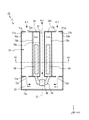
- FIG. 3 is a schematic cross-sectional view showing the main part of the atomization unit of the suction tool according to Embodiment 1;
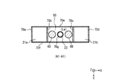
- FIG. 3 is a diagram schematically showing a cross section taken along line A1-A1 of FIG. 2;
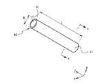
- 1 is a schematic perspective view of a molded body according to Embodiment 1.
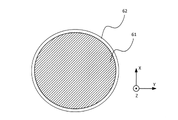
- FIG. FIG. 4B is a diagram schematically showing a cross section taken along the line AA of FIG. 4A;
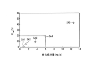
- FIG. 4 is a diagram showing the results of measuring the TPM reduction rate with respect to the amount of carbonized components contained in 1 g of extract.
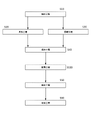
- FIG. 10 is a flowchart for explaining a manufacturing method according to Embodiment 2;
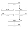
- FIG. 10 is a flowchart for explaining a manufacturing method according to Modification 1 of Embodiment 2;
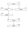
- FIG. 11 is a flowchart for explaining a manufacturing method according to Modification 2 of Embodiment 2;
- FIG. 1 is a perspective view schematically showing the appearance of a suction tool 10 according to this embodiment.
- the suction tool 10 according to the present embodiment is a non-combustion heating suction tool, specifically, a non-combustion heating electronic cigarette.
- the suction tool 10 extends in the direction of the central axis CL of the suction tool 10 .
- the suction tool 10 has a “longitudinal direction (the direction of the central axis CL),” a “width direction” perpendicular to the longitudinal direction, and a “thickness direction” perpendicular to the longitudinal direction and the width direction. , and has an external shape.
- the dimensions of the suction tool 10 in the longitudinal direction, width direction, and thickness direction decrease in this order.
- the Z-axis direction corresponds to the longitudinal direction
- the X-axis direction corresponds to It corresponds to the width direction
- the Y-axis direction corresponds to the thickness direction.
- the suction tool 10 has a power supply unit 11 and an atomization unit 12.
- the power supply unit 11 is detachably connected to the atomization unit 12 .
- a battery as a power supply, a control device, and the like are arranged inside the power supply unit 11.
- the atomization unit 12 is connected to the power supply unit 11, the power supply of the power supply unit 11 and the load 40 of the atomization unit 12, which will be described later, are electrically connected.
- the atomization unit 12 is provided with a discharge port 13 for discharging air (that is, air). Air containing aerosol is discharged from this discharge port 13 .
- air that is, air
- the user of the suction tool 10 can suck the air discharged from the discharge port 13 .
- the power supply unit 11 is provided with a sensor that outputs the value of the pressure change inside the suction tool 10 caused by the user's suction through the discharge port 13 .
- the sensor senses the start of sucking air and notifies the control device, which starts energizing the load 40 of the atomization unit 12, which will be described later. Further, when the user finishes sucking air, the sensor senses the finish of sucking air and informs the control device, and the control device stops energizing the load 40 .
- the power supply unit 11 may be provided with an operation switch for transmitting an air suction start request and an air suction end request to the control device by user's operation.
- the user can operate the operation switch to transmit an air suction start request or a suction end request to the control device.
- the control device Upon receiving the air suction start request and suction end request, the control device starts and terminates energization of the load 40 .
- the configuration of the power supply unit 11 as described above is the same as that of the power supply unit of a known suction tool as exemplified in Patent Document 2, for example, so further detailed description will be omitted.
- FIG. 2 is a schematic cross-sectional view showing the main part of the atomization unit 12 of the suction tool 10.
- FIG. 2 schematically shows a cross section of the main part of the atomization unit 12 taken along a plane including the central axis CL.
- FIG. 3 is a diagram schematically showing a cross section along line A1-A1 of FIG. 2 (that is, a cross section taken along a plane normal to the center axis CL).
- the atomization unit 12 will be described with reference to FIGS. 2 and 3.
- the atomization unit 12 includes a plurality of walls (walls 70a to 70g) extending in the longitudinal direction (the direction of the central axis CL), and a plurality of walls (walls 71a to 70g) extending in the width direction. ⁇ wall portion 71c).
- the atomization unit 12 also includes an air passage 20 , a wick 30 , an electrical load 40 , a liquid container 50 and a molding 60 . Note that the cross section of the molded body 60 in FIG. 3 is a rough shape, and for details, see FIG. 4B described later.
- the air passage 20 is a passage through which air passes when the user inhales air (that is, inhales aerosol).
- the air passage 20 according to this embodiment includes an upstream passage portion, a load passage portion 22 and a downstream passage portion 23 .
- the upstream passage portion according to the present embodiment includes a plurality of upstream passage portions, specifically, an upstream passage portion 21a (“first upstream passage portion”) and an upstream passage portion 21b. (“second upstream passage portion”).
- the upstream passage portions 21a and 21b are arranged upstream of the load passage portion 22 (upstream in the air flow direction). Downstream end portions of the upstream passage portions 21 a and 21 b communicate with the load passage portion 22 .
- the load passage portion 22 is a passage portion in which the load 40 is arranged.
- the downstream passage portion 23 is a passage portion arranged on the downstream side (downstream side in the air flow direction) of the load passage portion 22 .
- An upstream end portion of the downstream passage portion 23 communicates with the load passage portion 22 .
- a downstream end of the downstream passage portion 23 communicates with the discharge port 13 described above. Air that has passed through the downstream passage portion 23 is discharged from the discharge port 13 .
- the upstream passage portion 21a is provided in a region surrounded by the wall portion 70a, the wall portion 70b, the wall portion 70e, the wall portion 70f, the wall portion 71a, and the wall portion 71b.
- the upstream passage portion 21b is provided in a region surrounded by the wall portion 70c, the wall portion 70d, the wall portion 70e, the wall portion 70f, the wall portion 71a, and the wall portion 71b.
- the load passage portion 22 is provided in a region surrounded by the wall portion 70a, the wall portion 70d, the wall portion 70e, the wall portion 70f, the wall portion 71b, and the wall portion 71c.
- the downstream passage portion 23 is provided in a region surrounded by the tubular wall portion 70g.
- a hole 72a and a hole 72b are provided in the wall portion 71a. Air flows into the upstream passage portion 21a through the hole 72a, and flows into the upstream passage portion 21b through the hole 72b. Further, holes 72c and 72d are provided in the wall portion 71b. Air passing through the upstream passage portion 21a flows into the load passage portion 22 through the hole 72c, and air passing through the upstream passage portion 21b flows into the load passage portion 22 through the hole 72d.
- the direction of air flow in the upstream passage portions 21 a and 21 b is opposite to the direction of air flow in the downstream passage portion 23 .
- the direction of air flow in the upstream passage portions 21a and 21b is the -Z direction
- the direction of air flow in the downstream passage portion 23 is the Z direction.
- the upstream passage portion 21a and the upstream passage portion 21b according to the present embodiment sandwich the liquid storage portion 50 between the upstream passage portion 21a and the upstream passage portion 21b. As shown in FIG.
- the upstream passage portion 21a is a cross-sectional view cut along a cut plane normal to the central axis CL, and the liquid storage portion 50 is sandwiched between the upstream passage portions 21a. side (-X direction side).
- the upstream passage portion 21b is arranged on the other side (the side in the X direction) across the liquid storage portion 50 in this cross-sectional view.
- the upstream passage portion 21 a is arranged on one side of the liquid containing portion 50 in the width direction of the suction tool 10
- the upstream passage portion 21 b is arranged on the side of the liquid containing portion 50 in the width direction of the suction tool 10 . located on the other side.
- the wick 30 is a member for introducing the liquid in the liquid storage section 50 to the load 40 in the load passage section 22 .
- the specific configuration of the wick 30 is not particularly limited as long as it has such a function. 50 liquids are introduced to the load 40;
- the load 40 is an electrical load for introducing the liquid in the liquid containing portion 50 and atomizing the introduced liquid to generate an aerosol.
- a specific configuration of the load 40 is not particularly limited, and for example, a heating element such as a heater or an element such as an ultrasonic generator can be used.
- a heater is used as an example of the load 40 .
- a heating resistor that is, a heating wire
- a ceramic heater that is, a ceramic heater, a dielectric heating type heater, or the like
- a heating resistor is used as an example of this heater.
- the heater as the load 40 has a coil shape. That is, the load 40 according to this embodiment is a so-called coil heater. This coil heater is wound around a wick 30 .
- the load 40 is arranged in the wick 30 portion inside the load passage portion 22 as an example.
- the load 40 is electrically connected to the power supply and the control device of the power supply unit 11 described above, and heats up when electricity from the power supply is supplied to the load 40 (that is, heats up when energized). Also, the operation of the load 40 is controlled by a control device.
- the load 40 heats the liquid in the liquid containing portion 50 introduced into the load 40 through the wick 30 to atomize the liquid to generate an aerosol.
- the configurations of the wick 30 and the load 40 are the same as the wick and the load used in a known suction tool as exemplified in Patent Document 2, for example, so further detailed description will be omitted.
- the liquid storage part 50 is a part for storing a liquid such as a predetermined solvent or tobacco leaf extract (Le), which will be described later.
- the liquid storage portion 50 according to this embodiment is provided in a region surrounded by the wall portion 70b, the wall portion 70c, the wall portion 70e, the wall portion 70f, the wall portion 71a, and the wall portion 71b. Further, in the present embodiment, the downstream passage portion 23 described above is provided so as to penetrate the liquid storage portion 50 in the direction of the central axis CL.
- the atomization unit 12 may be provided to the user in a state in which the liquid is stored in the liquid storage portion 50, or provided to the user in a state in which the liquid storage portion 50 does not store the liquid. It is good also as a structure which introduces and uses.
- tobacco leaf extract (Le) containing tobacco leaf flavor components is used as a predetermined solvent.
- the specific type of the predetermined solvent is not particularly limited, for example, one substance selected from the group consisting of glycerin, propylene glycol, triacetin, 1,3-butanediol, and water, Alternatively, a liquid containing two or more substances selected from this group can be used. In this embodiment, glycerin and propylene glycol are used as examples of the predetermined solvent.
- flavor components of tobacco leaves include nicotine and neophytadiene.
- two molded bodies 60 according to the present embodiment are arranged inside the extraction liquid of the liquid storage section 50 .
- the number of molded bodies 60 is not limited to this, and may be one or three or more.
- FIG. 4A is a schematic perspective view of the molded body 60
- FIG. 4B is a diagram schematically showing the AA cross section of FIG. 4A, that is, the cross section perpendicular to the longitudinal direction of the molded body 60.
- the compact 60 includes a compact body 61 and a coating 62 (FIG. 4B).
- the compact main body 61 is formed by hardening tobacco leaves into a predetermined shape.
- the shape of the molded body 60 is not particularly limited, and may be, for example, a rod-like shape extending in a predetermined direction (that is, a shape whose length is longer than its width), or a cubic shape (having sides of the same length). ), or a sheet shape, or any other shape.
- the shape of the molded body 60 according to the present embodiment is rod-like as an example.
- the rod-shaped molded body 60 according to the present embodiment has, as an example, a rod-shaped polyhedron shape, and as an example, has a columnar shape with a circular cross section.
- the cross-sectional shape of the molded body 60 is not limited to a circle, and other examples include polygons (triangles, quadrilaterals, pentagons, or polygons having 6 or more corners).
- a sheet-shaped molded body 60 specifically, a paper sheet of tobacco leaves, a cast sheet of tobacco leaves, a rolled sheet of tobacco leaves, or the like can be used as the molded body 61 .
- the shape of the molded body 61 can also be appropriately selected in the same manner as the molded body 60 .
- the density (mass per unit volume) of the compact body 61 is, for example, 1100 mg/cm 3 or more and 1450 mg/cm 3 or less.
- the density of the compact body 61 is not limited to this, and may be less than 1100 mg/cm 3 or greater than 1450 mg/cm 3 .
- the material of the coating 62 is not particularly limited as long as it can suppress swelling of the compact body 61 as described later.
- Coating 62 may be solid or gel-like. As a result, the swelling of the compact body 61 can be suppressed more reliably.
- Coating 62 is preferably formed by solidifying or gelling a coating material.
- Coating 62 preferably includes or is formed using sodium silicate.
- the coating 62 is preferably formed by solidifying or gelling a coating material containing sodium silicate, and more preferably formed by solidifying or gelling water glass.
- water glass refers to an aqueous sodium silicate solution containing Na 2 O and SiO 2 .
- Water glass is inexpensive and easily available, and it is commercially available with a molar ratio n of SiO 2 /Na 2 O of 0.5 to 4.0, and is particularly preferred because it is readily available.
- the coating 62 may contain a wax ester.
- wax for example, can be used as the coating material.
- this wax include Microcrystalline WAX manufactured by Nippon Seiro Co., Ltd. (model number: Hi-Mic-1080 or model number: Hi-Mic-1090), and water-dispersed ionomer manufactured by Mitsui Chemicals (model number: Chemipearl S120). ), Mitsui Chemicals Hi-Wax (model number: 110P), or the like can be used.
- the coating 62 and coating material may contain corn protein.
- Zein model number: Kobayashi Zein DP-N manufactured by Kobayashi Koryo Co., Ltd.
- the coating 62 and coating material may include starch, HPMC (hydroxypropyl methylcellulose) or polyvinyl acetate.
- the coating 62 is preferably provided with a plurality of holes (fine holes) through which the flavor components remaining in the tobacco leaves can pass while suppressing the passage of the tobacco leaves. That is, the pores of the coating 62 may be of a size larger than the size of the flavoring component and smaller than the size of the tobacco leaves of the compact 60 . According to this configuration, it is possible to suppress the elution of the tobacco leaves into the liquid of the liquid containing portion 50 and to allow the flavor components remaining in the tobacco leaves to be eluted into the liquid.
- the specific size (diameter) of the holes provided in the coating 62 is not particularly limited, but as a specific example, a value selected from the range of 10 ⁇ m or more and 3 mm or less can be used. can.
- the coating 62 and the coating material can also contain a net-like mesh member. In this case as well, it is possible to suppress the elution of the tobacco leaves into the liquid of the liquid containing portion 50 while allowing the flavor components remaining in the tobacco leaves to be eluted into the liquid.
- the coating 62 and the coating material may contain resin.
- the tobacco leaves can be solidified to produce the compact 60 .
- the coating 62 suppresses swelling of the compact body 61 . Accordingly, it is possible to prevent the tobacco leaves contained in the molded article 60 from being dispersed in the liquid due to the molded article 60 cracking or collapsing due to swelling. In addition, it is possible to prevent tobacco leaves from adhering to the load and deteriorating the load due to dispersion.
- the coating 62 preferably covers 50% or more of the surface of the compact body 61, more preferably 90% or more, in order to enhance the effect of preventing swelling of the tobacco leaves contained in the compact body 61.
- the thickness and shape of the coating 62 are not particularly limited as long as it can cover at least a portion of the molded body 61 .
- width (that is, the outer diameter) (W), which is the length in the lateral direction of the molded body 60, and the total length (L), which is the length in the longitudinal direction of the molded body 60 are particularly limited.
- An example of numerical values is as follows. That is, as the width (W) of the molded body 60, a value selected from a range of, for example, 2 mm or more and 20 mm or less can be used. As the total length (L) of the molded body 60, a value selected from the range of, for example, 5 mm or more and 50 mm or less can be used. However, these values are merely examples of the width (W) and the total length (L) of the molded body 60, and the width (W) and the total length (L) of the molded body 60 are suitable for the size of the suction tool 10. value should be set.
- the suction using the suction tool 10 is performed as follows. First, when the user starts sucking air, the air passes through the upstream passage portions 21 a and 21 b of the air passage 20 and flows into the load passage portion 22 . Aerosol generated in the load 40 is added to the air that has flowed into the load passage portion 22 . This aerosol contains the flavor component eluted from the molded body 60 placed in the liquid of the liquid containing portion 50 and the flavor component of the liquid extract placed in the liquid containing portion 50 . The aerosol-added air passes through the downstream passage portion 23 and is discharged from the discharge port 13 to be sucked by the user.
- the tobacco leaf flavor component contained in the molded body 60 can be added to the aerosol generated by the load 40 . This makes it possible to fully enjoy the flavor of tobacco leaves.
- the molded tobacco leaf 60 coated with the coating 62 is arranged inside the liquid of the liquid storage portion 50, and the swelling of the tobacco leaves is prevented while molding. Since the body 60 and the electrical load 40 of the suction tool 10 are physically separated, it is possible to prevent tobacco leaves from adhering to the load 40 of the suction tool 10 . Thereby, deterioration of the load 40 of the suction tool 10 can be suppressed. Also, reduction in the usable amount of the liquid can be suppressed. Further, the coating 62 can be efficiently and inexpensively manufactured using coating materials such as those containing sodium silicate.
- the amount (mg) of the carbonized component contained in 1 g of the extract in which the compact 60 and the extract are placed is preferably 6 mg or less, more preferably 3 mg or less.
- the carbonized component contained in the liquid extract in which the molded body 60 is arranged specifically means the amount of the carbonized component contained in the liquid extracted before the molded body 60 is arranged, It corresponds to the sum of the amount of the carbonized component eluted into the extract from the compact 60 placed in the extract.
- carbonized component refers to a component that becomes a carbide when heated to 250°C.
- carbonized component refers to a component that does not form a carbide at a temperature of less than 250°C, but that forms a carbide when the temperature is maintained at 250°C for a predetermined period of time.
- the “amount (mg) of the carbonized component contained in 1 g of the extract in which the compact 60 is arranged” can be measured, for example, by the following method. First, a predetermined amount (g) of extraction liquid in which the molded body 60 is arranged is prepared. Next, this extract is heated to 180° C. to volatilize the solvent (liquid component) contained in the extract, thereby obtaining a “residue composed of non-volatile components”. The residue is then heated to 250° C. to carbonize the residue to obtain a carbide. The amount (mg) of this carbide is then measured. By the above method, the amount (mg) of charcoal contained in a predetermined amount (g) of liquid extract can be measured. The amount (mg) of the component can be calculated.
- FIG. 5 is a diagram showing the results of measuring the TPM reduction rate with respect to the amount of carbonized components contained in 1 g of the extract.
- the horizontal axis of FIG. 5 indicates the amount of carbonized components contained in 1 g of the extract, and the vertical axis indicates the TPM reduction rate (R TPM ) (%).
- the TPM reduction rate (R TPM : %) in FIG. 5 was measured by the following method. First, a plurality of suction tool samples having different amounts of carbonized components contained in 1 g of the extract were prepared. Specifically, five samples (sample SA1 to sample SA5) were prepared as samples of the plurality of suction tools. These five samples were prepared by the following steps.
- Step 1 20 (wt%) of potassium carbonate in terms of dry weight was added to tobacco raw material composed of tobacco leaves, and then heat distillation treatment was performed.
- the distillation residue after the heat distillation treatment is immersed in water of 15 times the weight of the tobacco raw material before the heat distillation treatment for 10 minutes, dehydrated with a dehydrator, and then dried with a dryer to obtain tobacco. A residue was obtained.
- Step 2 Next, a portion of the tobacco residue obtained in step 1 was washed with water to prepare a tobacco residue containing a small amount of char.
- Step 3 25 g of an immersion liquid (propylene glycol 47.5 wt%, glycerin 47.5 wt%, water 5 wt%) as an extract liquid was added to 5 g of the tobacco residue obtained in step 2, and the temperature of the immersion liquid was raised to 60. °C and allowed to stand. By varying the standing time (that is, the immersion time in the immersion liquid), the amount of carbonized component eluted into the immersion liquid (extract) was varied.
- an immersion liquid propylene glycol 47.5 wt%, glycerin 47.5 wt%, water 5 wt%
- the CRM 81 smoking condition is a condition in which 55 cc of aerosol is inhaled over 3 seconds multiple times every 30 seconds.
- the amount of total particulate matter collected by the Cambridge filter of the automatic smoking machine was then measured. Based on the measured amount of total particulate matter, the TPM reduction rate (R TPM ) was calculated using the following formula (1).
- the TPM reduction rate (R TPM ) in FIG. 5 was measured by the above method.
- R TPM (%) (1-TPM (201 puff to 250 puff) / TPM (1 puff to 50 puff)) x 100 (1)
- TPM Total Particle Molecule
- TPM (1 puff to 50 puff) indicates the amount of total particulate matter collected by the Cambridge filter from the 1st puff to the 50th puff of the automatic smoking machine.
- TPM (201 puff to 250 puff) indicates the amount of total particulate matter captured by the Cambridge filter from the 201st puff to the 250th puff of the automatic smoking machine.
- the TPM reduction rate (R TPM ) in Equation (1) is defined as "the amount of total particulate matter collected by the Cambridge filter from the 201st puff to the 250th puff of the automatic smoking machine. 1 minus the value obtained by dividing by the amount of total particulate matter collected by the Cambridge filter from the 1st puff to the 50th puff, and multiplied by 100.
- Embodiment 2 is an embodiment of a manufacturing method of the atomization unit 12 of the suction tool 10 .
- FIG. 6 is a flow chart for explaining the method of manufacturing the atomizing unit for a suction tool according to this embodiment.
- step S10 flavor components are extracted from tobacco leaves.
- the specific method of step S10 is not particularly limited, for example, the following method can be used.
- an alkaline substance is applied to tobacco leaves (referred to as alkaline treatment).
- a basic substance such as an aqueous solution of potassium carbonate can be used.
- the alkali-treated tobacco leaves are heated at a predetermined temperature (for example, a temperature of 80°C or more and less than 150°C) (referred to as heat treatment). Then, during this heat treatment, for example, one substance selected from the group consisting of glycerin, propylene glycol, triacetin, 1,3-butanediol, and water, or a substance selected from this group Two or more substances are brought into contact with tobacco leaves.
- a predetermined temperature for example, a temperature of 80°C or more and less than 150°C
- heat treatment for example, one substance selected from the group consisting of glycerin, propylene glycol, triacetin, 1,3-butanediol, and water, or a substance selected from this group Two or more substances are brought into contact with tobacco leaves.
- flavor components are included here
- the collection solvent for example, one substance selected from the group consisting of glycerin, propylene glycol, triacetin, 1,3-butanediol, and water, or two types selected from this group The above substances can be used.
- a collection solvent containing flavor components can be obtained (that is, flavor components can be extracted from tobacco leaves).
- step S10 can be configured without using the collection solvent as described above. Specifically, in this case, after subjecting the alkali-treated tobacco leaves to the above-described heat treatment, the components released from the tobacco leaves into the gas phase are cooled using a condenser or the like. can be condensed to extract flavor components.
- step S10 may be configured without the alkali treatment as described above.
- tobacco leaves tobacco leaves not subjected to alkali treatment
- step S10 tobacco leaves are treated with glycerin, propylene glycol, triacetin, 1,3-butanediol, and water.
- a selected substance or two or more substances selected from this group are added.
- the tobacco leaves to which this has been added are heated, and the components released during this heating are collected in a collection solvent or condensed using a condenser or the like. Flavor components can also be extracted by such a process.
- step S10 an aerosol in which one substance selected from the group consisting of glycerin, propylene glycol, triacetin, 1,3-butanediol, and water is aerosolized, or an aerosol selected from this group
- Tobacco leaves tobacco leaves that have not been subjected to alkali treatment
- the aerosol that has passed through the tobacco leaves is collected by a collection solvent.
- Flavor components can also be extracted by such a process.
- step S10 extraction step
- step S10 reduces "the amount of carbonized components that become carbonized when heated to 250 ° C.” contained in the flavor components extracted by the above-described method. It may further include According to this configuration, it is possible to effectively suppress adhesion of carbonized components to the load 40 . As a result, scorching of the load 40 can be effectively suppressed.
- a specific method for reducing the amount of the carbonized component contained in the extracted flavor component is not particularly limited, but for example, the component precipitated by cooling the extracted flavor component is
- the amount of carbonized components contained in the extracted flavor component may be reduced by filtering with filter paper or the like.
- the amount of carbonized components contained in the extracted flavor component may be reduced by centrifuging the extracted flavor component with a centrifuge.
- a reverse osmosis membrane RO filter
- step S10 After step S10, a molding process related to step S20 and a concentration process related to step S30, which will be described below, are executed.
- step S20 the "tobacco residue", which is the tobacco leaves after being extracted in the extraction step of step S10, is hardened and molded into a predetermined shape (in this embodiment, a rod shape as an example), thereby forming the compact 60. to manufacture.
- a predetermined shape in this embodiment, a rod shape as an example
- the tobacco residue may be washed with a cleaning liquid, and the tobacco residue after washing may be molded by the above-described method to manufacture the molded body 61.
- the amount of carbonized components contained in the tobacco residue is reduced as much as possible by washing, and the compact body 61 can be manufactured using the tobacco residue with the reduced amount of carbonized components.
- scorching of the load 40 can be effectively suppressed.
- step S30 the flavor components extracted in step S10 are concentrated. Specifically, in step S30 according to the present embodiment, the flavor components contained in the collection solvent containing the flavor components extracted in step S10 are concentrated.
- step S40 the flavor component extracted in the extraction process of step S10 (specifically, in the present embodiment, the flavor component after being concentrated in step S30 is added to the compact body 61 manufactured in step S20). Flavoring ingredients) are added.
- step S100 the covering process of step S100 is executed.
- step S100 the surface of the compact body 61 is covered with a coating material to form the coating 62.
- the molded body 60 having a structure in which the surface of the tobacco residue hardened into a predetermined shape is covered with the coating 62 can be manufactured.
- the method of forming the coating 62 is not particularly limited. For example, after forming a film of a liquid coating material containing sodium silicate on the surface of the molded body 61, solidification treatment or gelation treatment is performed by heating or addition of acid or salt. It can be performed.
- the tobacco leaves may be coated by solidifying the tobacco leaves appropriately added with a flavoring component using resin or a solution containing sodium silicate such as water glass in the molding step. good.
- step S100 the assembly process related to step S50 is executed. Specifically, in step S50, the atomization unit 12 in which the molded body 60 is not stored is prepared, and the molded body 60 after step S100 is stored in the liquid storage section 50 of the atomization unit 12. do.
- step S60 one substance selected from the group consisting of glycerin, propylene glycol, triacetin, 1,3-butanediol, and water, or two or more substances selected from this group contain liquids, including
- a flavor component may be added to the above-described liquid contained in the liquid container 50, apart from the flavor component added to the compact 60 in step S40.
- the accommodation step of step S60 may be performed before step S50. The same applies to the assembly process and housing process of the following modified examples.
- the atomization unit 12 of the suction tool 10 is manufactured.
- the manufactured atomization unit 12 is connected to the power supply unit 11 (FIG. 1), etc., and the suction tool 10 is manufactured.
- this embodiment can also be configured not to include step S30.
- step S40 the flavor component extracted in the extraction process of step S10 may be added to the compact 60 produced in step S20.
- the case where the present embodiment includes step S30 is preferable in that the amount of the flavor component contained in the molded body 60 can be increased compared to the case where it does not include step S30.
- this embodiment can also be configured not to include step S60. In this case, the user of the suction tool 10 can replenish the liquid container 50 by himself/herself.
- the atomization unit 12 of the suction tool 10 can be manufactured while effectively using the tobacco residue coated with the coating 62 as the material of the molded body 60. can be done. This can suppress the swelling of tobacco leaves. As a result, deterioration of the load 40 due to the adhesion of tobacco leaves can be suppressed, and reduction in the amount of the liquid in the liquid container 50 that can be used for suction can be suppressed.
- the coating 62 can be efficiently formed at low cost using resin, water glass, or the like, the atomization unit for the suction tool can be manufactured efficiently and at low cost.
- FIG. 7 is a flowchart for explaining a method of manufacturing the atomization unit 12 of the suction tool 10 according to Modification 1 of Embodiment 2. As shown in FIG. In the extraction step of step S10 in FIG. 7, flavor components are extracted from tobacco leaves. Since this step S10 is the same as step S10 described in FIG. 6, detailed description thereof will be omitted.
- step S10 the molding process related to step S20 and the concentration process related to step S30 are executed. Steps S20 and S30 according to this modification are the same as steps S20 and S30 described with reference to FIG. 6, respectively, so detailed description thereof will be omitted.
- step S20 the covering step of step S100A is performed.
- step S100A the molded body 61 obtained in step S20 is coated with the coating 62 described above, and the molded body 60 in which the molded body 61 is coated with the coating 62 is manufactured.
- step S45 the extract manufacturing process of step S45 is executed. Specifically, in step S45, the flavor component extracted in step S10 (specifically, in this modification, the flavor component after being concentrated in step S30) is added to a predetermined solvent. , to produce tobacco leaf extract.
- a predetermined solvent is not particularly limited, for example, one substance selected from the group consisting of glycerin, propylene glycol, triacetin, 1,3-butanediol, and water, Alternatively, two or more substances selected from this group can be used.
- step S50A the assembly process related to step S50A is executed. Specifically, in step S50A, the atomization unit 12 in which the molded body 60 is not stored is prepared, and the molded body 60 manufactured in step S100A is stored in the liquid storage section 50 of the atomization unit 12. do.
- step S50A the accommodation process of step S60A is executed. Specifically, in step S60A, the "tobacco leaf extract" produced in step S45 is stored in the liquid storage unit 50 in which the compact 60 is stored.
- the atomization unit 12 of the suction tool 10 is manufactured.
- step S100A a portion of the tobacco leaf extract may be added to the covered compact 60, and then step S50A may be performed.
- the manufacturing method according to this modified example as described above it is possible to manufacture the atomization unit 12 of the suction device 10 while effectively utilizing the tobacco residue coated with the coating 62 as the material of the molded body 60. can. This can suppress the swelling of tobacco leaves. As a result, it is possible to prevent tobacco leaves from adhering to the load and deteriorating the load, and it is possible to suppress a decrease in the amount of the liquid in the liquid container 50 that can be used for suction. . Furthermore, since the coating 62 can be efficiently formed using resin, water glass, or the like at low cost, the atomization unit for suction tools can be manufactured efficiently and at low cost.
- this modification can also be configured without step S30, as in the second embodiment described above.
- the tobacco leaf extract may be produced by adding the flavor component extracted in step S10 to a predetermined solvent.
- the modification including step S30 is preferable in that the amount of flavor components contained in the tobacco leaf extract can be increased compared to the modification not including step S30.
- FIG. 8 is a flowchart for explaining a manufacturing method of the atomization unit 12 of the suction tool 10 according to Modification 2 of Embodiment 2. As shown in FIG. In the extraction step of step S10 in FIG. 8, flavor components are extracted from tobacco leaves. Since this step S10 is the same as step S10 described in FIG. 6, detailed description thereof will be omitted.
- Step S10 the molding process related to step S20B and the concentration process related to step S30 are executed.
- Step S30 according to this modification is the same as step S30 described with reference to FIG. 6, so detailed description thereof will be omitted.
- step S20B the flavor component extracted in step S10 (specifically, in this modification, , Furthermore, the flavor component after being concentrated in step S30) is mixed to produce a mixture, and the mixture is solidified and molded into a predetermined shape (in this modification, a rod shape as an example), so that the molded body main body 61 to manufacture.
- step S20B the covering step of step S100B is performed.
- step S100B the molded body 61 obtained in step S20B is coated with the coating 62 described above, and the molded body 60 in which the molded body 61 is coated with the coating 62 is manufactured.
- step S100B the assembly process related to step S50B is executed.
- step S50B the atomization unit 12 in which the molded article 60 is not accommodated is prepared, and the molded article 60 manufactured in step S100B is accommodated in the liquid storage section 50 of the atomization unit 12 .
- step S60B the accommodation process of step S60B is performed.
- step S60B one substance selected from the group consisting of glycerin, propylene glycol, triacetin, 1,3-butanediol, and water, or A liquid containing two or more substances selected from this group is contained.
- a flavor component may be added to the above-described liquid contained in the liquid container 50 separately from the flavor component mixed with the tobacco residue in step S20B described above.
- this modification can also be configured without step S30, as in the second embodiment described above.
- step S20B the tobacco residue is mixed with the flavor component extracted in step S10 to produce a mixture, and the mixture is hardened and molded into a predetermined shape to produce molded body 60.
- the modification including step S30 is preferable in that the amount of the flavor component contained in the molded body 60 can be increased compared to the modification not including step S30.
- the manufacturing method according to this modified example as described above it is possible to manufacture the atomization unit 12 of the suction device 10 while effectively utilizing the tobacco residue coated with the coating 62 as the material of the molded body 60. can. This can suppress the swelling of tobacco leaves. As a result, it is possible to prevent tobacco leaves from adhering to the load and deteriorating the load, and it is possible to suppress a decrease in the amount of the liquid in the liquid container 50 that can be used for suction. . Furthermore, since the coating 62 can be efficiently formed using resin, water glass, or the like at low cost, the atomization unit for suction tools can be manufactured efficiently and at low cost.
- tobacco raw materials other than tobacco leaves may be used in place of tobacco leaves or in addition to tobacco leaves for the molded article and the extract. Even in this case, swelling of the tobacco raw material can be suppressed. In addition, it is possible to prevent the tobacco raw material contained in the molded article from being dispersed in the liquid due to the molded article cracking or crumbling due to swelling. In addition, it is possible to suppress the deterioration of the load caused by the tobacco raw material adhering to the load due to dispersion.
- tobacco raw materials refer to raw materials derived from tobacco plants such as tobacco leaves, backbones, stems and roots.
Landscapes
- Manufacture Of Tobacco Products (AREA)
Abstract
コーティング(62)によって被覆された、たばこ原料(61)を含むたばこ成形体(60)。
Description
本発明は、たばこ成形体、吸引具用霧化ユニット、吸引具、たばこ成形体の製造方法、及び、吸引具用霧化ユニットの製造方法に関する。
従来、非燃焼加熱型の吸引具として、所定の液体を収容する液体収容部と、この液体収容部の液体が導入されるとともに、導入された液体を霧化してエアロゾルを発生させる電気的な負荷と、を有する霧化ユニットを備え、この液体収容部の液体の内部に、たばこ葉の粉体が分散されたことを特徴とする吸引具が知られている(例えば、特許文献1参照)。
なお、他の先行技術文献として、特許文献2や特許文献3が挙げられる。特許文献2には、非燃焼加熱型の吸引具の基本的な構成態様が開示されている。特許文献3には、たばこ葉の抽出液に関する情報が開示されている。
上述の特許文献1に例示されるような、液体収容部の液体にたばこ葉等が含まれている従来の吸引具の場合、たばこ葉等が膨潤し、たばこ葉等が負荷に付着し負荷が劣化したり、液体収容部の液体のうち吸引のために使用可能な量が減少する。この点において、従来技術は改善の余地があった。
本発明は、上記のことを鑑みてなされたものであり、たばこ葉等のたばこ原料の膨潤を抑制することができる技術を提供することを目的の一つとする。
(態様1)
上記目的を達成するため、本発明の一態様に係るたばこ成形体は、コーティングによって被覆されたたばこ原料を含む。
上記目的を達成するため、本発明の一態様に係るたばこ成形体は、コーティングによって被覆されたたばこ原料を含む。
この態様によれば、コーティングがたばこ葉等のたばこ原料の膨張を防ぐので、たばこ原料の膨潤を抑制することができる。これにより、たばこ原料が負荷に付着し負荷が劣化することを防ぐことができる。また、膨潤されたたばこ原料に含まれる液体は液体収容部から排出されにくくなる傾向があるが、上記態様により、これを防ぎ、液体収容部の液体のうち、吸引のために使用可能な量が減少することを抑制することができる。
(態様2)
上記の態様1において、前記コーティングは、珪酸ナトリウムを含んでもよい。
上記の態様1において、前記コーティングは、珪酸ナトリウムを含んでもよい。
この態様によれば、水ガラス等を用いてコーティングを効率的に低コストで行うことができる。
(態様3)
上記の態様1において、前記コーティングは、樹脂を含んでもよい。
上記の態様1において、前記コーティングは、樹脂を含んでもよい。
この態様によれば、加工性等の樹脂の特性を生かし、コーティングを効率的に行うことができる。
(態様4)
上記の態様1から3において、前記コーティングは、固体またはゲル状であってもよい。
上記の態様1から3において、前記コーティングは、固体またはゲル状であってもよい。
この態様によれば、より確実にたばこ原料の膨潤を抑制することができる。
(態様5)
また、上記目的を達成するため、本発明の一態様に係る吸引具用霧化ユニットは、霧化用液体を収容するための液体収容部と、前記液体収容部に収容された上記の態様1から4のいずれかのたばこ成形体と、前記液体収容部の前記霧化用液体が導入されるとともに、導入された前記霧化用液体を霧化してエアロゾルを発生させる電気的な負荷とを備える。
また、上記目的を達成するため、本発明の一態様に係る吸引具用霧化ユニットは、霧化用液体を収容するための液体収容部と、前記液体収容部に収容された上記の態様1から4のいずれかのたばこ成形体と、前記液体収容部の前記霧化用液体が導入されるとともに、導入された前記霧化用液体を霧化してエアロゾルを発生させる電気的な負荷とを備える。
この態様によれば、たばこ原料の膨潤を抑制することにより、たばこ原料が負荷に付着し負荷が劣化することを防ぐことができ、また、液体収容部の液体のうち、吸引のために使用可能な量が減少することを抑制することが可能な吸引具用霧化ユニットを提供することができる。
(態様6)
また、上記の態様5において、前記液体収容部は、前記たばこ成形体と接触する前記霧化用液体を含む。
また、上記の態様5において、前記液体収容部は、前記たばこ成形体と接触する前記霧化用液体を含む。
この態様によれば、たばこ成形体に含まれる成分を、液体を介して霧化することにより、香味を調整することができる。また、あらかじめ霧化用液体を収容した吸引具を提供する場合、使用者は自ら霧化用液体を吸引具に導入する必要がない。
(態様7)
上記の態様5または6において、前記霧化用液体はたばこ抽出物をさらに含んでいてもよい。
上記の態様5または6において、前記霧化用液体はたばこ抽出物をさらに含んでいてもよい。
この態様によれば、たばこ抽出物に含まれる成分を、霧化用液体を介して霧化することにより、香味を調整することができる。
(態様8)
また、上記目的を達成するため、本発明の一態様に係る吸引具は、上記の態様5から7のいずれかに記載の吸引具用霧化ユニットを備える。
また、上記目的を達成するため、本発明の一態様に係る吸引具は、上記の態様5から7のいずれかに記載の吸引具用霧化ユニットを備える。
この態様によれば、たばこ原料の膨潤を抑制することにより、たばこ原料が負荷に付着し負荷が劣化することを防ぐことができ、また、液体収容部の液体のうち、吸引のために使用可能な量が減少することを抑制可能な吸引具を提供することができる。
(態様9)
また、上記目的を達成するため、本発明の一態様に係るたばこ成形体の製造方法は、たばこ原料をコーティングにより被覆する工程を含む。
また、上記目的を達成するため、本発明の一態様に係るたばこ成形体の製造方法は、たばこ原料をコーティングにより被覆する工程を含む。
この態様によれば、霧化ユニットにおいて、たばこ原料の膨潤を抑制することにより、たばこ原料が負荷に付着し負荷が劣化することを防ぐことができ、さらに、液体収容部の液体のうち、吸引のために使用可能な量が減少することを抑制することが可能なたばこ成形体を提供することができる。
(態様10)
上記態様9において、前記コーティングは、珪酸ナトリウムを用いて行われてもよい。
上記態様9において、前記コーティングは、珪酸ナトリウムを用いて行われてもよい。
この態様によれば、水ガラス等を用いてコーティングを効率的に低コストで行うことができる。
(態様11)
上記態様9において、前記コーティングは、樹脂を用いて行われてもよい。
上記態様9において、前記コーティングは、樹脂を用いて行われてもよい。
この態様によれば、加工性等の樹脂の特性を生かし、コーティングを効率的に行うことができる。
(態様12)
また、上記目的を達成するため、本発明の一態様に係る吸引具用霧化ユニットの製造方法は、上記の態様9から11に記載のたばこ成形体の製造方法により製造されたたばこ成形体を液体収容部に配置する組立工程を含む。
また、上記目的を達成するため、本発明の一態様に係る吸引具用霧化ユニットの製造方法は、上記の態様9から11に記載のたばこ成形体の製造方法により製造されたたばこ成形体を液体収容部に配置する組立工程を含む。
この態様によれば、たばこ原料の膨潤を抑制することにより、たばこ原料が負荷に付着し負荷が劣化することを防ぐことができ、また、液体収容部の液体のうち、吸引のために使用可能な量が減少することを抑制することが可能な吸引具用霧化ユニットを提供することができる。
(態様13)
上記の態様12において、前記液体収容部に、グリセリン、プロピレングリコール、トリアセチン、1,3-ブタンジオール、及び、水からなる群の中から選択される1種類以上の物質を含む液体を前記液体収容部に収容する収容工程をさらに含んでいてもよい。
上記の態様12において、前記液体収容部に、グリセリン、プロピレングリコール、トリアセチン、1,3-ブタンジオール、及び、水からなる群の中から選択される1種類以上の物質を含む液体を前記液体収容部に収容する収容工程をさらに含んでいてもよい。
この態様によれば、上記物質が香味成分の好適な溶媒となるため、効率よく香味を調整することができる。また、あらかじめ霧化用液体を収容した吸引具を提供する場合、使用者は自ら霧化用液体を吸引具に導入する必要がない。
本発明の態様によれば、たばこ葉等のたばこ原料の膨潤を抑制することができる。
(実施形態1)
以下、本発明の実施形態1に係る吸引具10について、図面を参照しつつ説明する。なお、本願の図面は、実施形態の特徴の理解を容易にするために模式的に図示されており、各構成要素の寸法比率等は実際のものと同じであるとは限らない。また、本願の図面には、必要に応じて、X-Y-Zの直交座標が図示されている。
以下、本発明の実施形態1に係る吸引具10について、図面を参照しつつ説明する。なお、本願の図面は、実施形態の特徴の理解を容易にするために模式的に図示されており、各構成要素の寸法比率等は実際のものと同じであるとは限らない。また、本願の図面には、必要に応じて、X-Y-Zの直交座標が図示されている。
図1は、本実施形態に係る吸引具10の外観を模式的に示す斜視図である。本実施形態に係る吸引具10は、非燃焼加熱型の吸引具であり、具体的には、非燃焼加熱型の電子たばこである。
本実施形態に係る吸引具10は、一例として、吸引具10の中心軸線CLの方向に延在している。具体的には、吸引具10は、一例として、「長手方向(中心軸線CLの方向)」と、長手方向に直交する「幅方向」と、長手方向及び幅方向に直交する「厚み方向」と、を有する外観形状を呈している。吸引具10の長手方向、幅方向、及び、厚み方向の寸法は、この順に小さくなっている。なお、本実施形態において、X-Y-Zの直交座標のうち、Z軸の方向(Z方向又は-Z方向)は長手方向に相当し、X軸の方向(X方向又は-X方向)は幅方向に相当し、Y軸の方向(Y方向又は-Y方向)は厚み方向に相当する。
吸引具10は、電源ユニット11と、霧化ユニット12とを有している。電源ユニット11は、霧化ユニット12に着脱自在に接続されている。電源ユニット11の内部には、電源としてのバッテリや、制御装置等が配置されている。霧化ユニット12が電源ユニット11に接続されると、電源ユニット11の電源と、霧化ユニット12の後述する負荷40とが電気的に接続される。
霧化ユニット12には、エア(すなわち、空気)を排出するための排出口13が設けられている。エアロゾルを含むエアは、この排出口13から排出される。吸引具10の使用時において、吸引具10のユーザは、この排出口13から排出されたエアを吸い込むことができる。
電源ユニット11には、排出口13を通じたユーザの吸引により生じた吸引具10の内部の圧力変化の値を出力するセンサが配置されている。ユーザによるエアの吸引が開始すると、このエアの吸引開始をセンサが感知して、制御装置に伝え、制御装置が後述する霧化ユニット12の負荷40への通電を開始させる。また、ユーザによるエアの吸引が終了すると、このエアの吸引終了をセンサが感知して、制御装置に伝え、制御装置が負荷40への通電を終了させる。
なお、電源ユニット11には、ユーザの操作によって、エアの吸引開始要求、及び、エアの吸引終了要求を制御装置に伝えるための操作スイッチが配置されていてもよい。この場合、ユーザが操作スイッチを操作することで、エアの吸引開始要求や吸引終了要求を制御装置に伝えることができる。そして、このエアの吸引開始要求や吸引終了要求を受けた制御装置は、負荷40への通電開始や通電終了を行う。
なお、上述したような電源ユニット11の構成は、例えば、特許文献2に例示されるような公知の吸引具の電源ユニットと同様であるので、これ以上詳細な説明は省略する。
図2は、吸引具10の霧化ユニット12の主要部を示す模式的断面図である。具体的には図2は、霧化ユニット12の主要部を、中心軸線CLを含む平面で切断した断面を模式的に図示している。図3は、図2のA1-A1線断面(すなわち、中心軸線CLを法線とする切断面で切断した断面)を模式的に示す図である。図2及び図3を参照しつつ、霧化ユニット12について説明する。
霧化ユニット12は、長手方向(中心軸線CLの方向)に延在する複数の壁部(壁部70a~壁部70g)を備えるとともに、幅方向に延在する複数の壁部(壁部71a~壁部71c)を備えている。また、霧化ユニット12は、エア通路20と、ウィック30と、電気的な負荷40と、液体収容部50と、成形体60とを備えている。なお、図3の成形体60の断面は概形であり、詳細は後述の図4Bを参照されたい。
エア通路20は、ユーザによるエアの吸引時(すなわち、エアロゾルの吸引時)に、エア(Air)が通過するための通路である。本実施形態に係るエア通路20は、上流通路部と、負荷通路部22と、下流通路部23とを備えている。本実施形態に係る上流通路部は、一例として、複数の上流通路部、具体的には、上流通路部21a(「第1の上流通路部」)、及び、上流通路部21b(「第2の上流通路部」)を備えている。
上流通路部21a,21bは、負荷通路部22よりも上流側(エア流動方向で上流側)に配置されている。上流通路部21a,21bの下流側端部は、負荷通路部22に連通している。負荷通路部22は、負荷40が内部に配置された通路部である。下流通路部23は、負荷通路部22よりも下流側(エア流動方向で下流側)に配置された通路部である。下流通路部23の上流側端部は負荷通路部22に連通している。また、下流通路部23の下流側端部は、前述した排出口13に連通している。下流通路部23を通過したエアは、排出口13から排出される。
具体的には、本実施形態に係る上流通路部21aは、壁部70aと壁部70bと壁部70eと壁部70fと壁部71aと壁部71bとによって囲まれた領域に設けられている。また、上流通路部21bは、壁部70cと壁部70dと壁部70eと壁部70fと壁部71aと壁部71bとによって囲まれた領域に設けられている。負荷通路部22は、壁部70aと壁部70dと壁部70eと壁部70fと壁部71bと壁部71cとによって囲まれた領域に設けられている。下流通路部23は、筒状の壁部70gによって囲まれた領域に設けられている。
壁部71aには、孔72a及び孔72bが設けられている。エアは、孔72aから上流通路部21aに流入し、孔72bから上流通路部21bに流入する。また、壁部71bには、孔72c及び孔72dが設けられている。上流通路部21aを通過したエアは、孔72cから負荷通路部22に流入し、上流通路部21bを通過したエアは、孔72dから負荷通路部22に流入する。
本実施形態において、上流通路部21a,21bにおけるエアの流動方向は、下流通路部23におけるエアの流動方向の反対方向である。具体的には、本実施形態において、上流通路部21a,21bにおけるエアの流動方向は、-Z方向であり、下流通路部23におけるエアの流動方向は、Z方向である。
また、図2及び図3を参照して、本実施形態に係る上流通路部21a及び上流通路部21bは、上流通路部21aと上流通路部21bとによって液体収容部50を挟持するように、液体収容部50に隣接して配置されている。
具体的には、本実施形態に係る上流通路部21aは、図3に示すように、中心軸線CLを法線とする切断面で切断した断面視で、液体収容部50を挟んで一方の側(-X方向の側)に配置されている。一方、上流通路部21bは、この断面視で、液体収容部50を挟んで他方の側(X方向の側)に配置されている。換言すると、上流通路部21aは、吸引具10の幅方向で、液体収容部50の一方の側に配置され、上流通路部21bは、吸引具10の幅方向で、液体収容部50の他方の側に配置されている。
ウィック30は、液体収容部50の液体を負荷通路部22の負荷40に導入するための部材である。このような機能を有するものであれば、ウィック30の具体的な構成は特に限定されるものではないが、本実施形態に係るウィック30は、一例として、毛管現象を利用して、液体収容部50の液体を負荷40に導入している。
負荷40は、液体収容部50の液体が導入されるとともに、この導入された液体を霧化してエアロゾルを発生させるための電気的な負荷である。負荷40の具体的な構成は特に限定されるものではなく、例えば、ヒータのような発熱素子や、超音波発生器のような素子を用いることができる。本実施形態では、負荷40の一例として、ヒータを用いている。このヒータとしては、発熱抵抗体(すなわち、電熱線)や、セラミックヒータ、誘電加熱式ヒータ等を用いることができる。本実施形態では、このヒータの一例として、発熱抵抗体を用いている。また、本実施形態において、負荷40としてのヒータは、コイル形状を有している。すなわち、本実施形態に係る負荷40は、いわゆるコイルヒータである。このコイルヒータは、ウィック30に巻き付けられている。
また、本実施形態に係る負荷40は、一例として、負荷通路部22の内部において、ウィック30の部分に配置されている。負荷40は、前述した電源ユニット11の電源や制御装置と電気的に接続されており、電源からの電気が負荷40に供給されることで発熱する(すなわち、通電時に発熱する)。また、負荷40の動作は、制御装置によって制御されている。負荷40は、ウィック30を介して負荷40に導入された液体収容部50の液体を加熱することで霧化して、エアロゾルを発生させる。
なお、このウィック30や負荷40の構成は、例えば特許文献2等に例示されるような公知の吸引具に用いられているウィックや負荷と同様であるので、これ以上詳細な説明は省略する。
液体収容部50は、後述する所定の溶媒またはたばこ葉の抽出液(Le)等の液体を収容するための部位である。本実施形態に係る液体収容部50は、壁部70bと壁部70cと壁部70eと壁部70fと壁部71aと壁部71bとによって囲まれた領域に設けられている。また、本実施形態において、前述した下流通路部23は、液体収容部50を、中心軸線CLの方向に貫通するように設けられている。霧化ユニット12は、液体収容部50に液体が収容されている状態でユーザに提供されてもよいし、液体収容部50に液体が収容されていない状態でユーザに提供され、ユーザが液体を導入して使用する構成としてもよい。
本実施形態では液体収容部50に収容される液体の一例として、所定の溶媒に、たばこ葉の香味成分が含有されたたばこ葉の抽出液(Le)を用いている。所定の溶媒の具体的な種類は特に限定されるものではないが、例えば、グリセリン、プロピレングリコール、トリアセチン、1,3-ブタンジオール、及び、水からなる群の中から選択される一つの物質、または、この群の中から選択される2種類以上の物質を含む液体を用いることができる。本実施形態では、所定の溶媒の一例として、グリセリン及びプロピレングリコールを用いている。
なお、たばこ葉の香味成分の具体例を挙げると、例えばニコチン、ネオフィタジエン等が挙げられる。
図2および図3が示す通り、本実施形態に係る成形体60は、液体収容部50の抽出液の内部に2個配置されている。但し、成形体60の個数は、これに限定されるものではなく、1個でもよく、3個以上であってもよい。
図4Aは、成形体60の模式的な斜視図であり、図4Bは、図4AのA-A断面、すなわち成形体60の長手方向に垂直な断面を模式的に示す図である。成形体60は、成形体本体61と、コーティング62とを含む(図4B)。成形体本体61は、たばこ葉が固められて所定形状に成形されたものである。
成形体60の形状は、特に限定されるものではなく、例えば、所定方向に延在する棒状(すなわち、長さが幅よりも長い形状)であってもよく、立方体形状(同じ長さの辺を有する形状)であってもよく、あるいは、シート形状であってもよく、その他の形状であってもよい。
本実施形態に係る成形体60の形状は、一例として、棒状である。具体的には、本実施形態に係る棒状の成形体60は、一例として、棒状の多面体形状を有しており、この一例として、円形の断面を有する円柱形状を有している。なお、成形体60の断面形状は円形に限定されるものではなく、他の例を挙げると、例えば、多角形(三角形、四角形、五角形、または、角の数が6以上の角形)等であってもよい。また、成形体60としてシート形状のものを用いる場合には、具体的には、成形体本体61として、たばこ葉の抄造シート、たばこ葉のキャストシート、たばこ葉の圧延シート等を用いることができる。成形体本体61の形状も、成形体60と同様に適宜選択することができる。
また、本実施形態において、成形体本体61の密度(単位体積当たりの質量)は、一例として、1100mg/cm3以上、1450mg/cm3以下である。但し、成形体本体61の密度は、これに限定されるものではなく、1100mg/cm3未満でもよく、あるいは、1450mg/cm3より大きくてもよい。
コーティング62は、後述するように成形体本体61の膨潤を抑制できれば、その材料は特に限定されない。コーティング62は、固体であるかまたはゲル状である。これにより、より確実に成形体本体61の膨潤を抑制することができる。コーティング62は、コーティング材が固化またはゲル化されて形成されたものであることが好ましい。
コーティング62は、珪酸ナトリウムを含むか、または珪酸ナトリウムを用いて形成されたものであることが好ましい。コーティング62は、珪酸ナトリウムを含むコーティング材が固化またはゲル化されて形成されたものであることが好ましく、水ガラスが固化またはゲル化されて形成されたものであることがより好ましい。ここで、水ガラスとは、Na2OおよびSiO2を含む珪酸ナトリウム水溶液を指す。水ガラスは安価で入手が容易であり、SiO2/Na2Oのモル比nが0.5~4.0のものが市販され特に入手が容易であるため好ましい。
コーティング62は、ワックスエステルを含んでもよい。この場合、コーティング材としては、例えば、ワックスを用いることができる。このワックスとしては、例えば、日本精蝋社製のマイクロクリスタンWAX(型番:Hi-Mic-1080、又は、型番:Hi-Mic-1090)や、三井化学社製の水分散アイオノマー(型番:ケミパールS120)や、三井化学社製のハイワックス(型番:110P)等を用いることができる。
あるいは、コーティング62およびコーティング材は、トウモロコシのたんぱく質を含んでもよい。この具体例を挙げると、小林香料社製のツェイン(型番:小林ツェインDP-N)が挙げられる。
あるいは、コーティング62およびコーティング材は、でんぷん、HPMC(ヒドロキシプロピルメチルセルロース)またはポリ酢酸ビニルを含んでもよい。
コーティング62は、たばこ葉が通過することを抑制しつつ、たばこ葉に残存した香味成分が通過することが可能な孔(微細な孔)が複数設けられていることが好ましい。すなわち、このコーティング62の孔は、香味成分の大きさよりも大きく且つ成形体60のたばこ葉の大きさよりも小さいサイズの孔であればよい。この構成によれば、たばこ葉が液体収容部50の液体に溶出することを抑制しつつ、たばこ葉に残存した香味成分を当該液体に溶出させることができる。
このコーティング62に設けられた孔の具体的なサイズ(直径)は、特に限定されるものではないが、具体例を挙げると、例えば、10μm以上3mm以下の範囲から選択された値を用いることができる。
なお、コーティング62およびコーティング材は、網状のメッシュ部材を含むこともできる。この場合においても、たばこ葉が液体収容部50の液体に溶出することを抑制しつつ、たばこ葉に残存した香味成分を当該液体に溶出させることができる。
また、コーティング62およびコーティング材は、樹脂を含んでもよい。この場合、たばこ葉を樹脂と混合することで、たばこ葉を固めて成形体60を製造することもできる。この場合においても、たばこ葉が液体収容部50の液体に溶出することを抑制しつつ、たばこ葉に残存した香味成分を当該液体に溶出させることができる。
コーティング62は、成形体本体61の膨潤を抑制する。これにより、膨潤によって成形体60が割れたり、崩壊することで成形体60に含まれるたばこ葉が液中に分散されることを防ぐことができる。また、分散によりたばこ葉が負荷に付着し負荷が劣化してしまうことも抑制できる。コーティング62は、成形体本体61の表面の50%以上を被覆することが、成形体本体61に含まれるたばこ葉の膨潤を防止する効果を高めるうえで好ましく、90%以上がより好ましい。しかしコーティング62は、成形体本体61の少なくとも一部を被覆することができればその厚さおよび形状は特に限定されない。
また、成形体60の短手方向の長さである幅(すなわち外径)(W)、及び、成形体60の長手方向の長さである全長(L)の具体的な値は、特に限定されるものではないが、数値の一例を挙げると、以下のとおりである。すなわち、成形体60の幅(W)として、例えば2mm以上20mm以下の範囲から選択された値を用いることができる。成形体60の全長(L)として、例えば5mm以上50mm以下の範囲から選択された値を用いることができる。但し、これらの値は成形体60の幅(W)及び全長(L)の一例に過ぎず、成形体60の幅(W)及び全長(L)は、吸引具10のサイズに応じて好適な値を設定すればよい。
吸引具10を用いた吸引は以下のように行われる。まず、ユーザがエアの吸引を開始した場合、エアはエア通路20の上流通路部21a,21bを通過して、負荷通路部22に流入する。負荷通路部22に流入したエアには、負荷40において発生したエアロゾルが付加される。このエアロゾルには、液体収容部50の液体に配置された成形体60から溶出した香味成分と、液体収容部50に抽出液を配置した場合その香味成分とが含まれている。このエアロゾルが付加されたエアは、下流通路部23を通過して排出口13から排出されて、ユーザに吸引される。
以上説明したような本実施形態に係る吸引具10によれば、負荷40が発生するエアロゾルに、成形体60に含まれるたばこ葉の香味成分を付加することができる。これにより、たばこ葉の香味を十分に味わうことができる。
また、本実施形態に係る吸引具10によれば、液体収容部50の液体の内部にコーティング62で被覆されたたばこ葉の成形体60が配置されており、たばこ葉の膨潤を防止しつつ成形体60と吸引具10の電気的な負荷40とが物理的に分離されているので、たばこ葉が吸引具10の負荷40に付着することを抑制することができる。これにより、吸引具10の負荷40が劣化することを抑制することができる。また、上記液体の使用可能な量の減少を抑制することができる。さらに、コーティング62は珪酸ナトリウムを含むコーティング材等を用いて効率的かつ低コストで製造することができる。
また、成形体60および抽出液が配置された状態の抽出液1g中に含まれる炭化成分の量(mg)は、6mg以下であることが好ましく、3mg以下であることがより好ましい。
この構成によれば、電気的な負荷40に付着する炭化成分の量をできるだけ抑制しつつ、たばこ葉の香味を味わうことができる。これにより、負荷40に焦げが発生することをできるだけ抑制しつつ、たばこ葉の香味を味わうことができる。
なお、「成形体60が配置された状態の抽出液中に含まれる炭化成分」は、具体的には、成形体60が配置される前の状態の抽出液に含まれる炭化成分の量と、抽出液に配置された成形体60から抽出液に溶出した炭化成分の量とを合計した値に相当する。
また、本実施形態において、「炭化成分」とは、250℃に加熱された場合に炭化物になる成分をいう。具体的には、「炭化成分」は、250℃未満の温度では炭化物にならないが、250℃の温度に所定時間維持した場合に炭化物になる成分をいう。
なお、この「成形体60が配置された状態の抽出液1g中に含まれる炭化成分の量(mg)」は、例えば、以下の手法によって測定することができる。まず、成形体60が配置された状態の抽出液を所定量(g)、準備する。次いで、この抽出液を180℃に加熱して、抽出液に含まれる溶媒(液体成分)を揮発させることで、「不揮発成分からなる残留物」を得る。次いで、この残留物を250℃に加熱することで残留物を炭化させて、炭化物を得る。次いで、この炭化物の量(mg)を測定する。以上の手法により、所定量(g)の抽出液に含まれる炭化物の量(mg)を測定することができ、この測定値に基づいて、抽出液1g中に含まれる炭化物の量(すなわち、炭化成分の量(mg))を算出することができる。
続いて、抽出液1g中に含まれる炭化成分の量とTPM減少率との関係について説明する。図5は、抽出液1g中に含まれる炭化成分の量に対するTPM減少率を測定した結果を示す図である。図5の横軸は、抽出液1g中に含まれる炭化成分の量を示し、縦軸は、TPM減少率(RTPM)(%)を示している。
図5のTPM減少率(RTPM:%)は以下の手法によって測定された。まず、抽出液1g中に含まれる炭化成分の量が互いに異なる複数の吸引具のサンプルを準備した。具体的には、この複数の吸引具のサンプルとして、5つのサンプル(サンプルSA1~サンプルSA5)を準備した。これらの5つのサンプルは、以下の工程によって準備されたものである。
(工程1)
たばこ葉からなるたばこ原料に対して、乾燥重量で20(wt%)の炭酸カリウムを添加し、次いで、加熱蒸留処理を行った。この加熱蒸留処理後の蒸留残渣を、加熱蒸留処理前のたばこ原料の重量に対して15倍量の水に10分間浸漬した後に、脱水機で脱水し、その後、乾燥機で乾燥させて、たばこ残渣を得た。
たばこ葉からなるたばこ原料に対して、乾燥重量で20(wt%)の炭酸カリウムを添加し、次いで、加熱蒸留処理を行った。この加熱蒸留処理後の蒸留残渣を、加熱蒸留処理前のたばこ原料の重量に対して15倍量の水に10分間浸漬した後に、脱水機で脱水し、その後、乾燥機で乾燥させて、たばこ残渣を得た。
(工程2)
次いで、工程1で得られたたばこ残渣の一部を水で洗浄することで、含有される炭化物の量の少ないたばこ残渣を準備した。
次いで、工程1で得られたたばこ残渣の一部を水で洗浄することで、含有される炭化物の量の少ないたばこ残渣を準備した。
(工程3)
次いで、工程2で得られたたばこ残渣5gに対して、抽出液としての浸漬リキッド(プロピレングリコール47.5wt%、グリセリン47.5wt%、水5wt%)を25g添加し、浸漬リキッドの温度を60℃にして静置した。この静置時間(すなわち、浸漬リキッドへの浸漬時間)を異ならせることで、浸漬リキッド(抽出液)に溶出する炭化成分の量を異ならせた。
次いで、工程2で得られたたばこ残渣5gに対して、抽出液としての浸漬リキッド(プロピレングリコール47.5wt%、グリセリン47.5wt%、水5wt%)を25g添加し、浸漬リキッドの温度を60℃にして静置した。この静置時間(すなわち、浸漬リキッドへの浸漬時間)を異ならせることで、浸漬リキッド(抽出液)に溶出する炭化成分の量を異ならせた。
以上の工程によって、浸漬リキッド(抽出液)1g中に含まれる炭化成分の量の異なる複数のサンプルを準備した。
次いで、上述した工程で準備された複数のサンプルについて、自動喫煙機(Borgwaldt社製の「Analytical Vaping Machine」)を用いて、「CRM(Coresta Recommended Method)81の喫煙条件」で、自動喫煙を行った。なお、CRM81の喫煙条件とは、3秒かけて55ccのエアロゾルを吸引することを、30秒毎に複数回行うという条件である。
次いで、自動喫煙機が有するケンブリッジフィルターに捕集された全粒子状物質の量を測定した。この測定された全粒子状物質の量に基づいて、下記式(1)を用いて、TPM減少率(RTPM)を算出した。以上の手法により、図5のTPM減少率(RTPM)は測定された。
RTPM(%)=(1-TPM(201puff~250puff)/TPM(1puff~50puff))×100・・・(1)
ここで、TPM(Total Particle Molecule)は、自動喫煙機のケンブリッジフィルターに捕集された全粒子状物質を示している。式(1)中の「TPM(1puff~50puff)」は、自動喫煙機の1パフ目から50パフ目までの間にケンブリッジフィルターに捕集された全粒子状物質の量を示している。式(1)中の「TPM(201puff~250puff)」は、自動喫煙機の201パフ目から250パフ目までの間にケンブリッジフィルターに捕集された全粒子状物質の量を示している。
すなわち、式(1)のTPM減少率(RTPM)は、「自動喫煙機の201パフ目から250パフ目までの間にケンブリッジフィルターに捕集された全粒子状物質の量を、自動喫煙機の1パフ目から50パフ目までの間にケンブリッジフィルターに捕集された全粒子状物質の量で割った値」を1から差し引いた値に、100を掛けた値、によって算出されている。
図5から分かるように、抽出液1g中に含まれる炭化成分の量とTPM減少率とは比例関係にある。そして、図5の特にサンプルSA1~サンプルSA4から分かるように、抽出液1g中に含まれる炭化成分の量が6mg以下の場合、TPM減少率を20%以下に抑えられる。
(実施形態2)
続いて、実施形態2について説明する。本実施形態は、吸引具10の霧化ユニット12の製造方法の実施形態である。図6は、本実施形態に係る吸引具用霧化ユニットの製造方法を説明するためのフロー図である。
続いて、実施形態2について説明する。本実施形態は、吸引具10の霧化ユニット12の製造方法の実施形態である。図6は、本実施形態に係る吸引具用霧化ユニットの製造方法を説明するためのフロー図である。
ステップS10に係る抽出工程においては、たばこ葉から香味成分を抽出する。このステップS10の具体的な手法は、特に限定されるものではないが、例えば、以下の手法を用いることができる。まず、アルカリ物質を、たばこ葉に付与する(アルカリ処理と称する)。ここで用いられるアルカリ物質としては、例えば、炭酸カリウム水溶液等の塩基性物質を用いることができる。
次いで、アルカリ処理が施されたたばこ葉を、所定の温度(例えば80℃以上且つ150℃未満の温度)で加熱する(加熱処理と称する)。そして、この加熱処理の際に、例えば、グリセリン、プロピレングリコール、トリアセチン、1,3-ブタンジオール、及び、水からなる群の中から選択される一つの物質、または、この群の中から選択される2種類以上の物質をたばこ葉に接触させる。
この加熱処理によって、たばこ葉から気相中に放出される放出成分(ここには香味成分が含まれている)を、所定の捕集溶媒に捕集させる。捕集溶媒としては、例えば、グリセリン、プロピレングリコール、トリアセチン、1,3-ブタンジオール、及び、水からなる群の中から選択される一つの物質、または、この群の中から選択される2種類以上の物質を用いることができる。これにより、香味成分を含む捕集溶媒を得ることができる(すなわち、たばこ葉から香味成分を抽出することができる)。
あるいは、ステップS10は、上述したような捕集溶媒を使用しない構成とすることもできる。具体的には、この場合、アルカリ処理が施されたたばこ葉に対して上記の加熱処理を施した後に、コンデンサー等を用いて冷却することで、たばこ葉から気相中に放出された放出成分を凝縮して、香味成分を抽出することもできる。
あるいは、ステップS10は、上述したようなアルカリ処理を行わない構成とすることもできる。具体的には、この場合、ステップS10において、たばこ葉(アルカリ処理が施されていないたばこ葉)に、グリセリン、プロピレングリコール、トリアセチン、1,3-ブタンジオール、及び、水からなる群の中から選択される一つの物質、または、この群の中から選択される2種類以上の物質を添加する。次いで、これが添加されたたばこ葉を加熱し、この加熱の際に放出された成分を、捕集溶媒に捕集させる、又は、コンデンサー等を用いて凝縮する。このような工程によっても、香味成分を抽出することができる。
あるいは、ステップS10において、グリセリン、プロピレングリコール、トリアセチン、1,3-ブタンジオール、及び、水からなる群の中から選択される一つの物質がエアロゾル化したエアロゾル、または、この群の中から選択される2種類以上の物質がエアロゾル化したエアロゾルを、たばこ葉(アルカリ処理が施されていないたばこ葉)を通過させ、このたばこ葉を通過したエアロゾルを捕集溶媒に捕集させる。このような工程によっても、香味成分を抽出することができる。
また、本実施形態に係るステップS10(抽出工程)は、上述したような手法で抽出された香味成分に含まれる、「250℃に加熱された場合に炭化物になる炭化成分の量」を低減させることをさらに含んでいてもよい。この構成によれば、負荷40に炭化成分が付着することを効果的に抑制することができる。この結果、負荷40に焦げが発生することを効果的に抑制することができる。
この抽出された香味成分に含まれる炭化成分の量を低減させるための具体的な方法は、特に限定されるものではないが、例えば、抽出された香味成分を冷却することで析出した成分を、濾紙等で濾過することで、抽出された香味成分に含まれる炭化成分の量を低減させてもよい。あるいは、抽出された香味成分を遠心分離器で遠心分離することで、抽出された香味成分に含まれる炭化成分の量を低減させてもよい。あるいは、逆浸透膜(ROフィルタ)を用いることで、抽出された香味成分に含まれる炭化成分の量を低減させてもよい。
ステップS10の後において、以下に説明するステップS20に係る成形工程及びステップS30に係る濃縮工程を実行する。
ステップS20においては、ステップS10に係る抽出工程で抽出された後のたばこ葉である「たばこ残渣」を、固めて所定形状(本実施形態では、一例として棒状)に成形することで、成形体60を製造する。
なお、ステップS20に係る成形工程において、たばこ残渣を洗浄液で洗浄し、この洗浄後のたばこ残渣を上述した方法で成形して成形体本体61を製造することもできる。この構成によれば、洗浄によって、たばこ残渣に含まれる炭化成分の量をできるだけ低減させ、この炭化成分の量が低減されたたばこ残渣を用いて成形体本体61を製造することができる。これにより、負荷40に炭化成分が付着することを効果的に抑制することができる。この結果、負荷40に焦げが発生することを効果的に抑制することができる。
一方、ステップS30に係る濃縮工程においては、ステップS10で抽出された香味成分を濃縮する。具体的には、本実施形態に係るステップS30においては、ステップS10で抽出された香味成分を含む捕集溶媒に含まれる香味成分を濃縮する。
ステップS20及びステップS30の後に、ステップS40に係る添加工程を実行する。ステップS40においては、ステップS20で製造された成形体本体61に、ステップS10に係る抽出工程で抽出された香味成分(具体的には、本実施形態では、さらに、ステップS30で濃縮された後の香味成分)を添加する。
ステップS40の後に、ステップS100に係る被覆工程を実行する。ステップS100においては、成形体本体61の表面を、コーティング材を用いて被覆し、コーティング62を形成する。これにより、成形体60として、所定形状に固められたたばこ残渣の表面がコーティング62で覆われた構造の成形体60を製造することができる。コーティング62の形成方法は特に限定されず、例えば、珪酸ナトリウムを含む液状のコーティング材の膜を成形体本体61の表面に形成した後、加熱または酸若しくは塩の添加等により固化処理またはゲル化処理を行うことができる。なお、ステップS40の被覆工程を行わず、成形工程において、樹脂または、水ガラス等の珪酸ナトリウムを含む溶液を用い、適宜香味成分が添加されたたばこ葉を固めることでたばこ葉を被覆してもよい。
ステップS100の後に、ステップS50に係る組立工程を実行する。具体的には、ステップS50においては、成形体60が収容されていない状態の霧化ユニット12を準備し、この霧化ユニット12の液体収容部50に、ステップS100の後の成形体60を収容する。
ステップS50の後に、ステップS60に係る収容工程を実行する。ステップS60において、グリセリン、プロピレングリコール、トリアセチン、1,3-ブタンジオール、及び、水からなる群の中から選択される一つの物質、または、この群の中から選択される2種類以上の物質を含む液体を収容する。なお、この場合において、前述したステップS40で成形体60に添加された香味成分とは別に、液体収容部50に収容された上記の液体に、香味成分をさらに添加してもよい。また、ステップS50の前にステップS60の収容工程を行ってもよい。以下の変形例の組立工程および収容工程についても同様である。
以上の工程で、本実施形態に係る吸引具10の霧化ユニット12が製造される。製造された霧化ユニット12は、電源ユニット11(図1)等と連結され、吸引具10が製造される。
なお、本実施形態は、ステップS30を含んでいない構成とすることもできる。この場合、ステップS40において、ステップS20で製造された成形体60に、ステップS10に係る抽出工程で抽出された香味成分を添加すればよい。但し、本実施形態がステップS30を含んでいる場合の方が、これを含んでいない場合に比較して、成形体60に含まれる香味成分の量を多くすることができる点で好ましい。また、本実施形態は、ステップS60を含んでいない構成とすることもできる。この場合、吸引具10のユーザは自ら液体収容部50に液体を補充することができる。
以上説明したような本実施形態に係る製造方法によれば、コーティング62により被覆されたたばこ残渣を成形体60の材料として有効的に活用しつつ、吸引具10の霧化ユニット12を製造することができる。これにより、たばこ葉の膨潤を抑制することができる。その結果、たばこ葉の付着による負荷40の劣化を抑制したり、液体収容部50の液体のうち、吸引のために使用可能な量が減少することを抑制することができる。また、樹脂または水ガラス等を用いてコーティング62を効率的に低コストで形成することができるため、効率的かつ低コストで吸引具用霧化ユニットを製造することができる。
(実施形態2の変形例1)
図7は、実施形態2の変形例1に係る吸引具10の霧化ユニット12の製造方法を説明するためのフロー図である。図7のステップS10に係る抽出工程において、たばこ葉から香味成分を抽出する。このステップS10は、図6で説明したステップS10と同様であるので、詳細な説明は省略する。
図7は、実施形態2の変形例1に係る吸引具10の霧化ユニット12の製造方法を説明するためのフロー図である。図7のステップS10に係る抽出工程において、たばこ葉から香味成分を抽出する。このステップS10は、図6で説明したステップS10と同様であるので、詳細な説明は省略する。
ステップS10の後において、ステップS20に係る成形工程、及び、ステップS30に係る濃縮工程を実行する。本変形例に係るステップS20及びステップS30は、ぞれぞれ、図6で説明したステップS20及びステップS30と同様であるので、詳細な説明は省略する。ステップS20の後にはステップS100Aに係る被覆工程を実行する。ステップS100Aでは、上述のコーティング62により、ステップS20で得られた成形体本体61を被覆し、成形体本体61がコーティング62で被覆された成形体60を製造する。
本変形例においては、ステップS30の後に、ステップS45に係る抽出液製造工程を実行する。具体的には、ステップS45において、ステップS10で抽出された香味成分(具体的には、本変形例では、さらに、ステップS30で濃縮された後の香味成分)を所定の溶媒に添加することで、たばこ葉の抽出液を製造する。所定の溶媒の具体的な種類は特に限定されるものではないが、例えば、グリセリン、プロピレングリコール、トリアセチン、1,3-ブタンジオール、及び、水からなる群の中から選択される一つの物質、または、この群の中から選択される2種類以上の物質を用いることができる。
ステップS100A及びステップS45の後に、ステップS50Aに係る組立工程を実行する。具体的には、ステップS50Aにおいて、成形体60が収容されていない状態の霧化ユニット12を準備し、この霧化ユニット12の液体収容部50に、ステップS100Aで製造された成形体60を収容する。ステップS50Aの後に、ステップS60Aに係る収容工程を実行する。具体的には、ステップS60Aにおいて、成形体60が収容された液体収容部50に、ステップS45で製造された「たばこ葉の抽出液」を収容する。以上の工程で、本変形例に係る吸引具10の霧化ユニット12が製造される。なお、ステップS100Aにおいて、被覆された成形体60に対して、たばこ葉の抽出液の一部を添加し、その後ステップS50Aに進んでもよい。
以上説明したような本変形例に係る製造方法においても、コーティング62により被覆されたたばこ残渣を成形体60の材料として有効的に活用しつつ、吸引具10の霧化ユニット12を製造することができる。これにより、たばこ葉の膨潤を抑制することができる。その結果、たばこ葉が負荷に付着し負荷が劣化することを防ぐことができ、また、液体収容部50の液体のうち、吸引のために使用可能な量が減少することを抑制することができる。さらに、樹脂または水ガラス等を用いてコーティング62を効率的に低コストで形成することができるため、効率的かつ低コストで吸引具用霧化ユニットを製造することができる。
なお、本変形例は、前述した実施形態2と同様に、ステップS30を含んでいない構成とすることもできる。この場合、ステップS45において、ステップS10で抽出された香味成分を所定の溶媒に添加することで、たばこ葉の抽出液を製造すればよい。但し、本変形例がステップS30を含んでいる場合の方が、これを含んでいない場合に比較して、たばこ葉の抽出液に含まれる香味成分の量を多くすることができる点で好ましい。
(実施形態2の変形例2)
図8は、実施形態2の変形例2に係る吸引具10の霧化ユニット12の製造方法を説明するためのフロー図である。図8のステップS10に係る抽出工程においては、たばこ葉から香味成分を抽出する。このステップS10は、図6で説明したステップS10と同様であるので、詳細な説明は省略する。
図8は、実施形態2の変形例2に係る吸引具10の霧化ユニット12の製造方法を説明するためのフロー図である。図8のステップS10に係る抽出工程においては、たばこ葉から香味成分を抽出する。このステップS10は、図6で説明したステップS10と同様であるので、詳細な説明は省略する。
ステップS10の後において、ステップS20Bに係る成形工程、及び、ステップS30に係る濃縮工程を実行する。本変形例に係るステップS30は、図6で説明したステップS30と同様であるので、詳細な説明は省略する。
本変形例に係るステップS20Bにおいては、ステップS10に係る抽出工程で抽出された後のたばこ葉である「たばこ残渣」に、ステップS10で抽出された香味成分(具体的には、本変形例では、さらに、ステップS30で濃縮された後の香味成分)を混合して混合物を製造し、この混合物を固めて所定形状(本変形例では、一例として棒状)に成形することで、成形体本体61を製造する。ステップS20Bの後にはステップS100Bに係る被覆工程を実行する。ステップS100Bでは、上述のコーティング62により、ステップS20Bで得られた成形体本体61を被覆し、成形体本体61がコーティング62で被覆された成形体60を製造する。
ステップS100Bの後に、ステップS50Bに係る組立工程を実行する。ステップS50Bにおいては、成形体60が収容されていない状態の霧化ユニット12を準備し、この霧化ユニット12の液体収容部50に、ステップS100Bで製造された成形体60を収容する。ステップS50Bの後に、ステップS60Bに係る収容工程を実行する。ステップS60Bにおいては、成形体60が収容された液体収容部50に、グリセリン、プロピレングリコール、トリアセチン、1,3-ブタンジオール、及び、水からなる群の中から選択される一つの物質、または、この群の中から選択される2種類以上の物質を含む液体を収容する。なお、この場合において、前述したステップS20Bでたばこ残渣に混合された香味成分とは別に、液体収容部50に収容された上記の液体に、香味成分をさらに添加してもよい。以上の工程で、本変形例に係る吸引具10の霧化ユニット12が製造される。
なお、本変形例は、前述した実施形態2と同様に、ステップS30を含んでいない構成とすることもできる。この場合、ステップS20Bにおいて、たばこ残渣に、ステップS10で抽出された香味成分を混合して、混合物を製造し、この混合物を固めて所定形状に成形することで、成形体60を製造すればよい。但し、本変形例がステップS30を含んでいる場合の方が、これを含んでいない場合に比較して、成形体60に含まれる香味成分の量を多くすることができる点で好ましい。
以上説明したような本変形例に係る製造方法においても、コーティング62により被覆されたたばこ残渣を成形体60の材料として有効的に活用しつつ、吸引具10の霧化ユニット12を製造することができる。これにより、たばこ葉の膨潤を抑制することができる。その結果、たばこ葉が負荷に付着し負荷が劣化することを防ぐことができ、また、液体収容部50の液体のうち、吸引のために使用可能な量が減少することを抑制することができる。さらに、樹脂または水ガラス等を用いてコーティング62を効率的に低コストで形成することができるため、効率的かつ低コストで吸引具用霧化ユニットを製造することができる。
(実施形態1および2の変形例)
上述の実施形態において、成形体および抽出液について、たばこ葉の代わりに、またはたばこ葉に加えて、たばこ葉以外のたばこ原料を用いてもよい。この場合でもたばこ原料の膨潤を抑制することができる。また、膨潤によって成形体が割れたり、崩壊することで成形体に含まれるたばこ原料が液中に分散されることを防ぐことができる。また、分散によりたばこ原料が負荷に付着し負荷が劣化してしまうことも抑制できる。ここで、たばこ原料とは、たばこ葉、中骨、茎および根等のたばこ植物由来の原料を指す。
上述の実施形態において、成形体および抽出液について、たばこ葉の代わりに、またはたばこ葉に加えて、たばこ葉以外のたばこ原料を用いてもよい。この場合でもたばこ原料の膨潤を抑制することができる。また、膨潤によって成形体が割れたり、崩壊することで成形体に含まれるたばこ原料が液中に分散されることを防ぐことができる。また、分散によりたばこ原料が負荷に付着し負荷が劣化してしまうことも抑制できる。ここで、たばこ原料とは、たばこ葉、中骨、茎および根等のたばこ植物由来の原料を指す。
以上、本発明の実施形態や変形例について詳述したが、本発明はかかる特定の実施形態や変形例に限定されるものではなく、特許請求の範囲に記載された本発明の要旨の範囲内において、種々の変形・変更が可能である。
次の優先権基礎出願の開示内容は引用文としてここに組み込まれる。
特許協力条約に基づく国際出願PCT/JP2021/026602号(2021年7月15日出願)
特許協力条約に基づく国際出願PCT/JP2021/026604号(2021年7月15日出願)
特許協力条約に基づく国際出願PCT/JP2021/026602号(2021年7月15日出願)
特許協力条約に基づく国際出願PCT/JP2021/026604号(2021年7月15日出願)
10 吸引具
12 霧化ユニット
20 エア通路
40 負荷
50 液体収容部
60 成形体
61 成形体本体
62 コーティング
Le 抽出液
12 霧化ユニット
20 エア通路
40 負荷
50 液体収容部
60 成形体
61 成形体本体
62 コーティング
Le 抽出液
Claims (13)
- コーティングによって被覆された、たばこ原料を含むたばこ成形体。
- 前記コーティングは、珪酸ナトリウムを含む、請求項1に記載のたばこ成形体。
- 前記コーティングは、樹脂を含む、請求項1に記載のたばこ成形体。
- 前記コーティングは、固体またはゲル状である、請求項1から3のいずれか一項に記載のたばこ成形体。
- 霧化用液体を収容するための液体収容部と、
前記液体収容部に収容された請求項1から4のいずれか一項に記載のたばこ成形体と、
前記液体収容部の前記霧化用液体が導入されるとともに、導入された前記霧化用液体を霧化してエアロゾルを発生させる電気的な負荷とを備える、吸引具用霧化ユニット。 - 前記液体収容部は、前記たばこ成形体と接触する前記霧化用液体を含む、請求項5に記載の吸引具用霧化ユニット。
- 前記霧化用液体はたばこ抽出物を含む、請求項5または6に記載の吸引具用霧化ユニット。
- 請求項5から7のいずれか一項に記載の吸引具用霧化ユニットを備える吸引具。
- たばこ原料をコーティングにより被覆する工程を含む、たばこ成形体の製造方法。
- 前記コーティングは、珪酸ナトリウムを用いて行われる、たばこ成形体の製造方法。
- 前記コーティングは、樹脂を用いて行われる、たばこ成形体の製造方法。
- 請求項9から11のいずれか一項に記載のたばこ成形体の製造方法により製造されたたばこ成形体を液体収容部に配置する組立工程を含む、吸引具用霧化ユニットの製造方法。
- 前記液体収容部に、グリセリン、プロピレングリコール、トリアセチン、1,3-ブタンジオール、及び、水からなる群の中から選択される1種類以上の物質を含む液体を前記液体収容部に収容する収容工程をさらに含む、請求項12に記載の吸引具用霧化ユニットの製造方法。
Applications Claiming Priority (4)
| Application Number | Priority Date | Filing Date | Title |
|---|---|---|---|
| PCT/JP2021/026604 WO2023286239A1 (ja) | 2021-07-15 | 2021-07-15 | 吸引具及び吸引具の製造方法 |
| JPPCT/JP2021/026604 | 2021-07-15 | ||
| PCT/JP2021/026602 WO2023286238A1 (ja) | 2021-07-15 | 2021-07-15 | 吸引具、及び、吸引具の霧化ユニットの製造方法 |
| JPPCT/JP2021/026602 | 2021-07-15 |
Publications (1)
| Publication Number | Publication Date |
|---|---|
| WO2023286291A1 true WO2023286291A1 (ja) | 2023-01-19 |
Family
ID=84918952
Family Applications (1)
| Application Number | Title | Priority Date | Filing Date |
|---|---|---|---|
| PCT/JP2021/046218 Ceased WO2023286291A1 (ja) | 2021-07-15 | 2021-12-15 | たばこ成形体、吸引具用霧化ユニット、吸引具、たばこ成形体の製造方法、及び、吸引具用霧化ユニットの製造方法 |
Country Status (1)
| Country | Link |
|---|---|
| WO (1) | WO2023286291A1 (ja) |
Citations (4)
| Publication number | Priority date | Publication date | Assignee | Title |
|---|---|---|---|---|
| WO2018122978A1 (ja) * | 2016-12-27 | 2018-07-05 | 日本たばこ産業株式会社 | 加熱型香味吸引器 |
| JP2018523985A (ja) * | 2015-06-29 | 2018-08-30 | フィリップ・モーリス・プロダクツ・ソシエテ・アノニム | エアロゾル発生システムのためのカートリッジおよび装置 |
| JP2020174586A (ja) * | 2019-04-18 | 2020-10-29 | 日本たばこ産業株式会社 | 加熱式たばこおよびその製造方法 |
| WO2020230577A1 (ja) * | 2019-05-13 | 2020-11-19 | 日本たばこ産業株式会社 | 非燃焼加熱型香味吸引物品、及び、電気加熱型香味吸引システム |
-
2021
- 2021-12-15 WO PCT/JP2021/046218 patent/WO2023286291A1/ja not_active Ceased
Patent Citations (4)
| Publication number | Priority date | Publication date | Assignee | Title |
|---|---|---|---|---|
| JP2018523985A (ja) * | 2015-06-29 | 2018-08-30 | フィリップ・モーリス・プロダクツ・ソシエテ・アノニム | エアロゾル発生システムのためのカートリッジおよび装置 |
| WO2018122978A1 (ja) * | 2016-12-27 | 2018-07-05 | 日本たばこ産業株式会社 | 加熱型香味吸引器 |
| JP2020174586A (ja) * | 2019-04-18 | 2020-10-29 | 日本たばこ産業株式会社 | 加熱式たばこおよびその製造方法 |
| WO2020230577A1 (ja) * | 2019-05-13 | 2020-11-19 | 日本たばこ産業株式会社 | 非燃焼加熱型香味吸引物品、及び、電気加熱型香味吸引システム |
Similar Documents
| Publication | Publication Date | Title |
|---|---|---|
| JP6698876B2 (ja) | 加熱型香味吸引器 | |
| JPWO2021215496A5 (ja) | ||
| JP7136531B2 (ja) | 使い捨て液状エアロゾル発生物品及びエアロゾル発生装置 | |
| WO2023105746A1 (ja) | 吸引具、及び、吸引具の霧化ユニットの製造方法 | |
| WO2023286238A1 (ja) | 吸引具、及び、吸引具の霧化ユニットの製造方法 | |
| WO2023112129A1 (ja) | 霧化ユニットの製造方法 | |
| WO2023112130A1 (ja) | 霧化ユニットの製造方法 | |
| WO2023162195A1 (ja) | 吸引具用霧化ユニット、吸引具、及び、吸引具用霧化ユニットの製造方法 | |
| WO2023188376A1 (ja) | 霧化ユニット及びその製造方法、並びに吸引具 | |
| WO2023162197A1 (ja) | 吸引具用霧化ユニット、吸引具、及び、吸引具用霧化ユニットの製造方法 | |
| JP7710519B2 (ja) | 吸引具及び吸引具の製造方法 | |
| WO2023112191A1 (ja) | たばこ成形体、吸引具用霧化ユニット、吸引具、たばこ成形体の製造方法、及び、吸引具用霧化ユニットの製造方法 | |
| JP7813350B2 (ja) | 霧化ユニット及びその製造方法、並びに吸引具 | |
| WO2023112132A1 (ja) | 吸引具及び吸引具の製造方法 | |
| JP7799812B2 (ja) | 霧化ユニット及びその製造方法、並びに吸引具 | |
| WO2023112190A1 (ja) | たばこ成形体、吸引具用霧化ユニット、吸引具、たばこ成形体の製造方法、及び、吸引具用霧化ユニットの製造方法 | |
| WO2023188324A1 (ja) | 霧化ユニット及びその製造方法、並びに吸引具 | |
| WO2023188323A1 (ja) | 霧化ユニット及びその製造方法、並びに吸引具 | |
| WO2023188436A1 (ja) | 霧化ユニット及びその製造方法、並びに吸引具 | |
| WO2023188325A1 (ja) | 霧化ユニット及びその製造方法、並びに吸引具 | |
| WO2023188435A1 (ja) | 霧化ユニット及びその製造方法、並びに吸引具 | |
| WO2023112291A1 (ja) | 霧化ユニット及び吸引具 | |
| WO2023112293A1 (ja) | 霧化ユニット及び吸引具 | |
| WO2023248475A1 (ja) | 霧化ユニット及びその製造方法、並びに吸引具 | |
| WO2023188322A1 (ja) | 霧化ユニット及びその製造方法、並びに吸引具 |
Legal Events
| Date | Code | Title | Description |
|---|---|---|---|
| 121 | Ep: the epo has been informed by wipo that ep was designated in this application |
Ref document number: 21950227 Country of ref document: EP Kind code of ref document: A1 |
|
| NENP | Non-entry into the national phase |
Ref country code: DE |
|
| 122 | Ep: pct application non-entry in european phase |
Ref document number: 21950227 Country of ref document: EP Kind code of ref document: A1 |
|
| NENP | Non-entry into the national phase |
Ref country code: JP |