WO2023281889A1 - Rotary cutting tool - Google Patents
Rotary cutting tool Download PDFInfo
- Publication number
- WO2023281889A1 WO2023281889A1 PCT/JP2022/016737 JP2022016737W WO2023281889A1 WO 2023281889 A1 WO2023281889 A1 WO 2023281889A1 JP 2022016737 W JP2022016737 W JP 2022016737W WO 2023281889 A1 WO2023281889 A1 WO 2023281889A1
- Authority
- WO
- WIPO (PCT)
- Prior art keywords
- cutting edge
- cutting
- angle
- cutting tool
- chipping
- Prior art date
Links
- 238000005520 cutting process Methods 0.000 title claims abstract description 128
- 239000000463 material Substances 0.000 description 7
- 238000003801 milling Methods 0.000 description 7
- YLZOPXRUQYQQID-UHFFFAOYSA-N 3-(2,4,6,7-tetrahydrotriazolo[4,5-c]pyridin-5-yl)-1-[4-[2-[[3-(trifluoromethoxy)phenyl]methylamino]pyrimidin-5-yl]piperazin-1-yl]propan-1-one Chemical compound N1N=NC=2CN(CCC=21)CCC(=O)N1CCN(CC1)C=1C=NC(=NC=1)NCC1=CC(=CC=C1)OC(F)(F)F YLZOPXRUQYQQID-UHFFFAOYSA-N 0.000 description 3
- 230000000052 comparative effect Effects 0.000 description 3
- 239000012141 concentrate Substances 0.000 description 3
- 229910001141 Ductile iron Inorganic materials 0.000 description 2
- 229910000831 Steel Inorganic materials 0.000 description 2
- 241000375392 Tana Species 0.000 description 2
- 238000010586 diagram Methods 0.000 description 2
- 239000011295 pitch Substances 0.000 description 2
- 239000010959 steel Substances 0.000 description 2
- VZSRBBMJRBPUNF-UHFFFAOYSA-N 2-(2,3-dihydro-1H-inden-2-ylamino)-N-[3-oxo-3-(2,4,6,7-tetrahydrotriazolo[4,5-c]pyridin-5-yl)propyl]pyrimidine-5-carboxamide Chemical compound C1C(CC2=CC=CC=C12)NC1=NC=C(C=N1)C(=O)NCCC(N1CC2=C(CC1)NN=N2)=O VZSRBBMJRBPUNF-UHFFFAOYSA-N 0.000 description 1
- 229910000838 Al alloy Inorganic materials 0.000 description 1
- 229910001018 Cast iron Inorganic materials 0.000 description 1
- 101100536354 Drosophila melanogaster tant gene Proteins 0.000 description 1
- 235000002492 Rungia klossii Nutrition 0.000 description 1
- 244000117054 Rungia klossii Species 0.000 description 1
- 229910001315 Tool steel Inorganic materials 0.000 description 1
- 229910045601 alloy Inorganic materials 0.000 description 1
- 239000000956 alloy Substances 0.000 description 1
- 238000005219 brazing Methods 0.000 description 1
- 239000000919 ceramic Substances 0.000 description 1
- 239000000470 constituent Substances 0.000 description 1
- 239000002826 coolant Substances 0.000 description 1
- 230000001788 irregular Effects 0.000 description 1
- 238000003754 machining Methods 0.000 description 1
- 238000004519 manufacturing process Methods 0.000 description 1
- 238000000034 method Methods 0.000 description 1
- 238000003466 welding Methods 0.000 description 1
Images


Classifications
-
- B—PERFORMING OPERATIONS; TRANSPORTING
- B23—MACHINE TOOLS; METAL-WORKING NOT OTHERWISE PROVIDED FOR
- B23C—MILLING
- B23C5/00—Milling-cutters
- B23C5/02—Milling-cutters characterised by the shape of the cutter
- B23C5/06—Face-milling cutters, i.e. having only or primarily a substantially flat cutting surface
Definitions
- the present invention relates to rotary cutting tools such as milling cutters.
- the present invention was completed in view of the above circumstances, and the problem to be solved is to provide a rotary cutting tool with excellent chipping resistance and a stable life.
- the rotary cutting tool of the present invention that solves the above problems has a single rake face, a cutting angle of more than 0 ° and less than 90 °, a true rake angle of -42 ° or more and -13 ° or less, a main cutting edge
- the tilt angle is -5° or more and less than +5°.
- the wiper blade has a convex R shape in the tip direction.
- the rotary cutting tool of the present invention has the above-described constituent elements, so that there are no places where stress is concentrated during cutting, the chipping resistance is improved compared to conventional tools, and a stable life can be obtained. Moreover, since there is no need to apply negative chamfer to the blade edge, the blade can be manufactured at a lower cost than before.
- FIG. 1 is a cross-sectional view of a rotary cutting tool according to an embodiment
- FIG. FIG. 4 is an explanatory diagram showing the entering angle of the main cutting edge, the true rake angle, the inclination angle of the main cutting edge, the axial rake, and the radial rake of the rotary cutting tool of the present embodiment
- 4 is a graph showing the true rake angle dependence of the cutting distance at which chipping occurred in the rotary cutting tool of Example 1.
- FIG. 4 is a graph showing the main cutting edge inclination angle dependence of the cutting distance at which chipping occurred in the rotary cutting tool of Example 1.
- FIG. 4 is an enlarged photograph of the tip of the rotary cutting tool of Example 1 at a cutting distance of 8.1 m.
- the rotary cutting tool of the present invention will be described in detail below based on an embodiment.
- the rotary cutting tool of this embodiment is a tool that has a main cutting edge formed on the outer periphery and can perform cutting on the outer periphery. A main cutting edge can also be formed on the tip side.
- the rotary cutting tool of the present embodiment can be suitably employed in milling cutters such as face mills and end mills. It is preferable that the milling cutter of the present embodiment is used particularly for processing steel materials.
- the side of the rotary cutting tool in contact with the workpiece in the rotation axis direction is called the front end, and the side opposite to the front end is called the rear end.
- the numerical values described in this specification can be arbitrarily adopted as the upper or lower limit when newly defining a numerical range, and furthermore, even if the numerical value adopted as the numerical range is included, it is not included. Also good.
- the rotary cutting tool of this embodiment has a main cutting edge made of a hard sintered body.
- the hard sintered body is preferably made of ceramics such as CBN.
- the size of the rotary cutting tool of this embodiment is not particularly limited.
- the outer diameter can be 10 mm, 15 mm, 20 mm, 25 mm, 30 mm as lower limits, and 500 mm, 300 mm, 200 mm, 100 mm, etc. as upper limits.
- the drawings in this specification are schematic diagrams, and scales and detailed structures are emphasized or omitted for ease of explanation. Moreover, even if they are different, the same reference numerals may be attached to those having the same function.
- the rotary cutting tool of this embodiment is a face mill, and rotates counterclockwise when viewed from the tip side.
- the rotary cutting tool of this embodiment as shown in FIG. 1, has a body 1 and 16 tips 2 uniformly fixed to the outer circumference of the tip of the body.
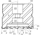
- FIG. 1 is a cross-sectional view of the body 1 cut so as to include the rotation axis AX, the lower part is the tip side, the upper part is the rear end side, and the rake face of the rightmost tip 2 among the plurality of tips 2 is this side.
- suitable for Both ends of the main cutting edge not only have a clear intersection with other sides of the insert (such as the wiper edge) as shown in this figure, but can also have a shape that is gently connected to the other sides.
- the rake face consists of one face.
- the rake face for which it is determined whether or not it is composed of one face is the face near the main cutting edge.
- the rotary cutting tool of this embodiment has a single surface near the main cutting edge.
- the vicinity of the main cutting edge is a portion within the feed amount per tooth from the main cutting edge.
- the vicinity of the wiper blade is also composed of one surface.
- the rake face is preferably configured as a flat surface because it facilitates manufacturing.
- the rake face in FIG. 1 is the face from the boundary line 23 toward the main cutting edge 21.
- the boundary line 23 is a line for defining the rake face, and is a parallel line with a certain distance from the main cutting edge 21. It has a feature that can be distinguished from the vicinity of the boundary line 23 in terms of appearance and shape. I don't have it.
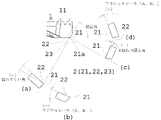
- FIG. 2 is an enlarged view of the rightmost insert 2 in FIG. ing.
- Each line of sight (a) to (d) passes through the plane containing the corner 21a and the rotation axis AX, and all pass through the corner 21a.
- the line of sight (a) is for measuring the true rake angle and is an extension of the main cutting edge 21 .
- Line of sight (b) is for measuring the radial rake and is parallel to the axis of rotation AX.
- the line of sight (c) is for measuring the inclination angle of the main cutting edge and is perpendicular to the main cutting edge.
- the line of sight (d) is for measuring axial rake and is perpendicular to the axis of rotation AX. Note that "(-)" in the lines of sight (a) to (d) in FIG. 2 indicates that the angle shown in the drawing has a negative value.
- the body 1 is made of alloy tool steel.
- the body 1 has a length of 49.5 mm in the direction of the rotation axis AX, an outer diameter of 62 mm, and a substantially cylindrical outer shape.
- the body 1 has a fitting hole 15 formed in the rear end side 1a so that it can be connected to a processing device.
- the fitting hole 15 penetrates to the tip portion, and the tip hole 14 expands to the vicinity of the tip 2 at the tip portion, so that the coolant can be supplied through the tip hole 14 .
- the face mill is fastened to the processing device on the rear end side by bolts from the tip hole 14 .
- the body 1 may be splittable. For example, the portion to which the chip 2 is fixed and the other portion can be divided in the axial direction. By forming the material other than the portion where the tip 2 is fixed from an aluminum alloy or the like, it is possible to reduce the weight and cost. Moreover, it is not necessary to replace the entire body 1 when replacing the tip 2 .
- Chips 2 are fixed to the outer periphery of the tip of the body 1 at regular pitches (or irregular pitches) in the circumferential direction.
- the method of fixing the tip 2 is not particularly limited, brazing or welding can be used.
- the chip 2 can be removably fixed by a bolt (not shown) or a clamping mechanism (not shown).
- a groove 11 is formed on the front side of the tip 2 in the rotation direction (counterclockwise direction of the tip 2 when viewed from the tip side).
- a relief 12 is formed on the rear side of the tip 2 in the rotational direction.
- the main cutting edge 21 and the wiper edge 22 are formed at an angle of 120° with the corner 21a as the intersection point.
- the wiper blade 22 has a shape that bulges slightly in the tip direction (a shape in which the center bulges outward: a convex R shape). Width of the wiper blade 22 is 1.7 mm, and length of projection of the most swollen portion at the center from a line connecting both ends of the wiper blade 22 is about 1.8 ⁇ m.
- the protruding length can be about 1 ⁇ m to 4 ⁇ m.
- the insert 2 fixed to the body 1 has an entering angle of more than 0° and less than 90°, a true rake angle of -13° to -42°, and a main cutting edge inclination angle of -5° to +5°.
- the main cutting edge 21 may have two or more cutting angles, an R-shaped main cutting edge, or a combination thereof.
- the cutting angles can have upper limits of 65°, 75°, and 85° and lower limits of 15°, 20°, and 25°, and can be combined arbitrarily.
- the cutting angle affects the ratio of the axial component force to the radial component force of the cutting force and the amount and size of burrs, and can be arbitrarily selected according to the intended cutting. For example, if the upper limit is exceeded, the cutting force in the radial direction increases and tool vibration tends to occur.
- the true rake angle can have upper limits of -20°, -17°, -13° and lower limits of -35°, -30°, -25°, and can be combined arbitrarily.
- the smaller the true rake angle the larger the cutting edge angle and the stronger the cutting edge.
- T TanR x sinE + tanA x cosE.
- R the radial rake
- A the axial rake
- E the entering angle.
- the upper limit of the inclination angle of the main cutting edge is 4°, 2°, and the lower limit is -4°, -2°, which can be combined arbitrarily. In particular, it is preferably in the range of -1° to 1°, more preferably about 0°.
- Radial rake R and axial rake A are automatically determined when the entering angle, true rake angle, and main cutting edge inclination angle are set.
- the rotary cutting tool of the present invention will be described in detail below based on Example 1.
- a work material was cut using the milling cutter of the test example described in Table 1.
- the milling cutter for each test had a single cBN tip and an outer diameter of 63 mm.
- a plate material of ductile cast iron FCD600 having a width of 25 mm was used as a work material, and a vertical machining center was used as a processing apparatus.
- the cutting conditions were a cutting speed Vc of 600 m/min and a feed per tooth fz of 0.05 mm.
- the presence or absence of chipping of the main cutting edge of the milling cutter of each test example was observed at cutting distances of 2.7 m and 8.1 m, and Table 1 shows the cutting distances at which chipping occurred.
- FIG. 3 shows a graph showing the true rake angle dependence of the chipped cutting distance
- FIG. 4 shows a graph showing the main cutting edge inclination angle dependence of the chipped cutting distance.
- the cutting distance at which chipping occurs is 8.1 m to 8.1 m.
- the data represented by ⁇ are data in which chipping was observed at that cutting distance
- the data represented by ⁇ are data in which chipping was not observed at that cutting distance.
- the data represented by ⁇ indicates that the true rake angle is -33.6° and chipping occurs at a cutting distance of 2.7 m, but the inclination angle of the main cutting edge, which will be described later, is 10.6°. This data is far outside the scope of the invention.
- the main cutting edge inclination angle is more than -6.2° and less than 5°
- the cutting distance at which chipping occurs is 8.1 m to 8.1 m. I found out.
- the rotary cutting tool of the present invention will be described in detail below based on Example 2. It was cut using the face mill of the test example described in Table 2.
- the milling cutter in each test example used cBN inserts had 16 blades in Test Example 2-1 and 4 blades in Test Example 2-2, and had an outer diameter of 63 mm.
- Test Example 2-1 no negative chamfer was formed, and the rake face consisted of one surface. , and ridges are formed where the respective negative chamfers intersect.
- a plate material of ductile cast iron FCD600 having a width of 25 mm was used as a work material, and a vertical machining center was used as a processing apparatus.
- the cutting conditions were a cutting speed Vc of 600 m/min, a feed amount per blade of 0.05 mm, and an axial depth of cut of 0.3 mm.
- the presence or absence of chipping of the cutting edge of the main cutting edge of the face mill of each test example was observed at cutting distances of 13.5 m, 27 m, 54 m, and 108 m.
- Test Example 2-1 chipping did not occur up to a cutting distance of 108 m, and stable processing was possible, while Test Example 2-2 gradually chipped from a cutting distance of 13.5 m. increased, and chipping occurred on all blades at a cutting distance of 108 m.
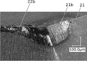
- FIGS. 7 and 8 Photographs of the chip of Test Example 2-1 (cutting distance 108 m) with no chipping and the chip of Test Example 2-2 (cutting distance 108 m) with chipping are shown in FIGS. 7 and 8, respectively. It was found that, in the insert with no chipping, the flank 21b of the main cutting edge 21 and the flank 22b of the wiper edge 22 were evenly worn, and the ridge line of the main cutting edge 21 was maintained. On the other hand, it was found that chipping occurred on the main cutting edge and on the ridge line where the negative chamfer surfaces formed on the main cutting edge and the wiper edge intersect.
Abstract
The present invention addresses the problem of providing a rotary cutting tool having excellent chipping resistance, and a stable lifespan. In a rotary cutting tool of the present invention that solves the above problem, a rake face is composed of one face, a cutting edge angle is greater than 0° and less than 90°, a true rake angle is between -42° and -13° inclusive, and an inclination angle of a major cutting edge is greater than or equal to -5° and less than +5°. In particular, a flat drag 22 preferably has a protruding round shape.
Description
本発明は、フライスなどの回転切削工具に関する。
The present invention relates to rotary cutting tools such as milling cutters.
従来の鋳鉄をはじめとする高硬度鋼加工用のフェースミルは、刃先強度確保の観点から刃角を大きくするため、負のすくい角になる様に設計されている。そのため、一般的には15~45°程度のネガチャンファが刃先に付与されているため、主切れ刃とさらい刃とが為す角には、ネガチャンファ部に稜線が生じることが不可避となっている。この稜線の一部には切削時に応力が集中するため、これを起点とした欠けの発生リスクを常に伴っていた。そのため、刃先の摩耗による寿命に到達する前に欠けが発生してしまい、寿命のブレが大きくなった。そこで、欠け発生の一因である応力が集中する箇所を減らした刃先設計を行う必要がある。
Conventional face mills for machining high-hardness steel, including cast iron, are designed to have a negative rake angle in order to increase the cutting edge angle from the perspective of ensuring cutting edge strength. Therefore, since negative chamfer of about 15 to 45° is generally applied to the cutting edge, it is inevitable that a ridge line is formed in the negative chamfer portion at the angle formed by the main cutting edge and the wiper edge. . Since stress concentrates on a part of this ridgeline during cutting, there is always a risk of chipping starting from this ridgeline. As a result, chipping occurs before the end of the service life due to wear of the cutting edge, resulting in large fluctuations in the service life. Therefore, it is necessary to design the cutting edge so as to reduce the places where stress concentrates, which is one of the causes of chipping.
本発明は上記実情に鑑み完成したものであり、耐欠損性に優れ、安定した寿命をもつ回転切削工具を提供することを解決すべき課題とする。
The present invention was completed in view of the above circumstances, and the problem to be solved is to provide a rotary cutting tool with excellent chipping resistance and a stable life.
上記課題を解決する本発明の回転切削工具は、すくい面が一つの面からなり、切込角が0°超90°未満、真のすくい角が-42°以上-13°以下、主切れ刃傾き角が-5°以上+5°未満である。
特に、さらえ刃が先端方向に凸R形状となっていることが好ましい。 The rotary cutting tool of the present invention that solves the above problems has a single rake face, a cutting angle of more than 0 ° and less than 90 °, a true rake angle of -42 ° or more and -13 ° or less, a main cutting edge The tilt angle is -5° or more and less than +5°.
In particular, it is preferable that the wiper blade has a convex R shape in the tip direction.
本発明の回転切削工具は、上述した構成要素をもつことにより、切削時に応力が集中する箇所が発生せず、従来よりも耐欠損性が向上し、安定した寿命が得られる。また、ネガチャンファを刃先に付与する必要がなくなるため、従来よりも安価に製造することが出来る。
The rotary cutting tool of the present invention has the above-described constituent elements, so that there are no places where stress is concentrated during cutting, the chipping resistance is improved compared to conventional tools, and a stable life can be obtained. Moreover, since there is no need to apply negative chamfer to the blade edge, the blade can be manufactured at a lower cost than before.
本発明の回転切削工具について実施形態に基づき以下詳細に説明を行う。本実施形態の回転切削工具は、外周に主切れ刃が形成されており、外周にて切削加工を行うことができる工具である。先端側についても主切れ刃が形成されていることもできる。本実施形態の回転切削工具は、フェースミル、エンドミルなどのフライスに好適に採用できる。本実施形態のフライスは、特に鉄鋼材料加工に用いるものであることが好ましい。なお、本明細書中における回転切削工具の回転軸方向における被加工物に接する側を先端、先端の反対側を後端と称する。なお、本明細書中に記載された数値は、数値範囲を新たに規定する際にその上限又は下限として任意に採用可能であり、更にはその数値範囲として採用された数値を含んでも含まなくても良い。
The rotary cutting tool of the present invention will be described in detail below based on an embodiment. The rotary cutting tool of this embodiment is a tool that has a main cutting edge formed on the outer periphery and can perform cutting on the outer periphery. A main cutting edge can also be formed on the tip side. The rotary cutting tool of the present embodiment can be suitably employed in milling cutters such as face mills and end mills. It is preferable that the milling cutter of the present embodiment is used particularly for processing steel materials. In this specification, the side of the rotary cutting tool in contact with the workpiece in the rotation axis direction is called the front end, and the side opposite to the front end is called the rear end. In addition, the numerical values described in this specification can be arbitrarily adopted as the upper or lower limit when newly defining a numerical range, and furthermore, even if the numerical value adopted as the numerical range is included, it is not included. Also good.
本実施形態の回転切削工具は、主切れ刃が硬質焼結体から形成されている。硬質焼結体はCBNなどのセラミックスにより形成されていることが好ましい。本実施形態の回転切削工具の大きさは特に限定しない。外径が、下限値として、10mm、15mm、20mm、25mm、30mm、上限値として、500mm、300mm、200mm、100mmなどにすることができる。なお、本明細書における図面は模式図であり、説明を容易にするために縮尺や細部の構造について強調や省略を行っている。また、別個のものであっても同機能のものに同じ符号をつける場合がある。
The rotary cutting tool of this embodiment has a main cutting edge made of a hard sintered body. The hard sintered body is preferably made of ceramics such as CBN. The size of the rotary cutting tool of this embodiment is not particularly limited. The outer diameter can be 10 mm, 15 mm, 20 mm, 25 mm, 30 mm as lower limits, and 500 mm, 300 mm, 200 mm, 100 mm, etc. as upper limits. It should be noted that the drawings in this specification are schematic diagrams, and scales and detailed structures are emphasized or omitted for ease of explanation. Moreover, even if they are different, the same reference numerals may be attached to those having the same function.
(実施形態)
本実施形態の回転切削工具はフェースミルであり、先端側から見て反時計回りに回転する。本実施形態の回転切削工具は、図1に示すように、ボデー1とボデーの先端部の外周に均等に固定された16個のチップ2とを有する。 (embodiment)
The rotary cutting tool of this embodiment is a face mill, and rotates counterclockwise when viewed from the tip side. The rotary cutting tool of this embodiment, as shown in FIG. 1, has abody 1 and 16 tips 2 uniformly fixed to the outer circumference of the tip of the body.
本実施形態の回転切削工具はフェースミルであり、先端側から見て反時計回りに回転する。本実施形態の回転切削工具は、図1に示すように、ボデー1とボデーの先端部の外周に均等に固定された16個のチップ2とを有する。 (embodiment)
The rotary cutting tool of this embodiment is a face mill, and rotates counterclockwise when viewed from the tip side. The rotary cutting tool of this embodiment, as shown in FIG. 1, has a
図1は、回転軸AXを含むようにボデー1を切断した断面図であり、下方が先端側、上方が後端側、複数のチップ2のうち一番右のチップ2のすくい面がこちら側に向いている。主切れ刃の両端は、本図のようにチップの他の辺(さらえ刃など)との交点を明確に有する場合だけでなく、他の辺となだらかに接続された形状をもつこともできる。ここで、すくい面は1つの面から構成される。1つの面から構成されているかどうかが判断されるすくい面とは、主切れ刃近傍の面である。つまり、本実施形態の回転切削工具は、主切れ刃の近傍が1つの面にて形成されている。これは、主切れ刃の近傍に2つ以上の面が交わる稜線が存在するとその稜線に応力が集中して欠けが発生し易くなるからである。主切れ刃の近傍とは、主切れ刃からおおよそ1刃当たりの送り量以内の部位である。さらえ刃を有する場合には、さらえ刃の近傍についても1つの面で構成されることが好ましい。特に製造が容易になるため、すくい面は平面で構成することが好ましい。
FIG. 1 is a cross-sectional view of the body 1 cut so as to include the rotation axis AX, the lower part is the tip side, the upper part is the rear end side, and the rake face of the rightmost tip 2 among the plurality of tips 2 is this side. suitable for Both ends of the main cutting edge not only have a clear intersection with other sides of the insert (such as the wiper edge) as shown in this figure, but can also have a shape that is gently connected to the other sides. Here, the rake face consists of one face. The rake face for which it is determined whether or not it is composed of one face is the face near the main cutting edge. In other words, the rotary cutting tool of this embodiment has a single surface near the main cutting edge. This is because if there is a ridgeline where two or more surfaces intersect in the vicinity of the main cutting edge, stress concentrates on the ridgeline and chipping is likely to occur. The vicinity of the main cutting edge is a portion within the feed amount per tooth from the main cutting edge. In the case of having a wiper blade, it is preferable that the vicinity of the wiper blade is also composed of one surface. In particular, the rake face is preferably configured as a flat surface because it facilitates manufacturing.
図1におけるすくい面は、境界線23から主切れ刃21に向けての面である。ここで、境界線23は、すくい面を規定するための線であり、主切れ刃21と一定の距離を持つ平行な線というのみでその境界線23近傍と外見・形状では区別ができる特徴をもつものではない。
The rake face in FIG. 1 is the face from the boundary line 23 toward the main cutting edge 21. Here, the boundary line 23 is a line for defining the rake face, and is a parallel line with a certain distance from the main cutting edge 21. It has a feature that can be distinguished from the vicinity of the boundary line 23 in terms of appearance and shape. I don't have it.
図2は、図1における一番右のチップ2を拡大しており、視線(a)~(d)から見たときの主切れ刃21及びさらえ刃22の向きが分かるようにチップ2を示している。各視線(a)~(d)は、角21a及び回転軸AXを含む平面上を通り、全て角21aを通過しており、各視線から見たときに紙面と平行な方向を基準とした角度を算出する。視線(a)は真のすくい角を測定するためのもので、主切れ刃21の延長線である。視線(b)はラジアルレーキを測定するためのもので、回転軸AXと平行である。
FIG. 2 is an enlarged view of the rightmost insert 2 in FIG. ing. Each line of sight (a) to (d) passes through the plane containing the corner 21a and the rotation axis AX, and all pass through the corner 21a. Calculate The line of sight (a) is for measuring the true rake angle and is an extension of the main cutting edge 21 . Line of sight (b) is for measuring the radial rake and is parallel to the axis of rotation AX.
視線(c)は主切れ刃傾き角を測定するためのもので、主切れ刃と垂直方向である。視線(d)はアキシャルレーキを測定するためのもので、回転軸AXと垂直方向である。なお、図2の視線(a)~(d)において「(-)」と示すのは、図面上で示す角度が負の値をもつことを表す。
The line of sight (c) is for measuring the inclination angle of the main cutting edge and is perpendicular to the main cutting edge. The line of sight (d) is for measuring axial rake and is perpendicular to the axis of rotation AX. Note that "(-)" in the lines of sight (a) to (d) in FIG. 2 indicates that the angle shown in the drawing has a negative value.
ボデー1は合金工具鋼から形成されている。ボデー1は、回転軸AX方向の長さが49.5mmで外径が62mm、外形が略円筒状の形態をもつ。ボデー1は、後端側1aには、加工装置に接続できるような嵌合孔15が形成されている。嵌合孔15は、先端部まで貫通しており、先端孔14は、先端部にてチップ2の近傍まで拡がっており、先端孔14を介したクーラントの供給を行うことができる。先端孔14からボルトにより後端側の加工装置にフェースミルは締結される。更にボデー1は分割可能なものであっても良い。例えば、チップ2を固定する部分と、それ以外の部分とを軸方向で分割することができる。チップ2を固定する部分以外の材質をアルミニウム合金などから構成することで軽量で安価にすることができる。また、チップ2の交換時にボデー1全体を交換する必要が無くなる。
The body 1 is made of alloy tool steel. The body 1 has a length of 49.5 mm in the direction of the rotation axis AX, an outer diameter of 62 mm, and a substantially cylindrical outer shape. The body 1 has a fitting hole 15 formed in the rear end side 1a so that it can be connected to a processing device. The fitting hole 15 penetrates to the tip portion, and the tip hole 14 expands to the vicinity of the tip 2 at the tip portion, so that the coolant can be supplied through the tip hole 14 . The face mill is fastened to the processing device on the rear end side by bolts from the tip hole 14 . Furthermore, the body 1 may be splittable. For example, the portion to which the chip 2 is fixed and the other portion can be divided in the axial direction. By forming the material other than the portion where the tip 2 is fixed from an aluminum alloy or the like, it is possible to reduce the weight and cost. Moreover, it is not necessary to replace the entire body 1 when replacing the tip 2 .
ボデー1の先端部の外周には、周方向に等ピッチ(不等ピッチでもよい)でチップ2が固定されている。チップ2の固定方法は特に限定しないが、ろう付や溶接により行うことができる。更に、チップ2は、ボルト(図略)やクランプ機構(図略)により取り外し自在に固定することもできる。チップ2の回転方向前側(先端側から見てチップ2の反時計回り方向)には、溝11が形成されている。チップ2の回転方向後側には、逃げ12が形成されている。
Chips 2 are fixed to the outer periphery of the tip of the body 1 at regular pitches (or irregular pitches) in the circumferential direction. Although the method of fixing the tip 2 is not particularly limited, brazing or welding can be used. Furthermore, the chip 2 can be removably fixed by a bolt (not shown) or a clamping mechanism (not shown). A groove 11 is formed on the front side of the tip 2 in the rotation direction (counterclockwise direction of the tip 2 when viewed from the tip side). A relief 12 is formed on the rear side of the tip 2 in the rotational direction.
チップ2は、主切れ刃21とさらえ刃22とが角21aを交点として120°の角度で形成されている。さらえ刃22は、僅かに先端方向に凸に膨らんだ形状(中央が外方向に膨らんだ形状:凸R形状)をもつ。さらえ刃22の刃幅は1.7mmであり、さらえ刃22の刃の両端を結んだ線分から中央の最も膨らんだ部位が突出する長さは、1.8μm程度である。この突出する長さは、1μm~4μm程度にすることができる。
In the insert 2, the main cutting edge 21 and the wiper edge 22 are formed at an angle of 120° with the corner 21a as the intersection point. The wiper blade 22 has a shape that bulges slightly in the tip direction (a shape in which the center bulges outward: a convex R shape). Width of the wiper blade 22 is 1.7 mm, and length of projection of the most swollen portion at the center from a line connecting both ends of the wiper blade 22 is about 1.8 μm. The protruding length can be about 1 μm to 4 μm.
ボデー1に固定したチップ2は、切込角が0°超90°未満、真のすくい角が-13°~-42°、主切れ刃傾き角が-5°~+5°の範囲である。
The insert 2 fixed to the body 1 has an entering angle of more than 0° and less than 90°, a true rake angle of -13° to -42°, and a main cutting edge inclination angle of -5° to +5°.
主切れ刃21は2つ以上の切込角を有するものや、R形状の主切れ刃、またはそれらを結合してもよい。
The main cutting edge 21 may have two or more cutting angles, an R-shaped main cutting edge, or a combination thereof.
切込角は、上限値が65°、75°、85°、下限値が15°、20°、25°とすることができ、任意に組み合わせ可能である。切込角は、切削力の軸方向分力と径方向分力の比率とバリの多寡およびその大小に影響しており、目的とする切削に合わせて任意に選択することができる。例えば、上限値以上であれば径方向の切削力が大きくなり工具振動が発生しやすくなり、下限値以下であれば切削面にバリが生じやすくなる。
The cutting angles can have upper limits of 65°, 75°, and 85° and lower limits of 15°, 20°, and 25°, and can be combined arbitrarily. The cutting angle affects the ratio of the axial component force to the radial component force of the cutting force and the amount and size of burrs, and can be arbitrarily selected according to the intended cutting. For example, if the upper limit is exceeded, the cutting force in the radial direction increases and tool vibration tends to occur.
真のすくい角は上限値が-20°、-17°、-13°、下限値が-35°、-30°、-25°とすることができ、任意に組み合わせ可能である。真のすくい角が小さいほど刃角を大きく取ることができ、刃先強度は増加するが、一方、切削抵抗は大きくなり、刃先にかかる負荷は大きくなる。下限値以上、上限値以下とすることで、刃先強度と刃先にかかる負荷のバランスが取れ、切削時に欠けを発生させず安定した寿命を得ることができる。
The true rake angle can have upper limits of -20°, -17°, -13° and lower limits of -35°, -30°, -25°, and can be combined arbitrarily. The smaller the true rake angle, the larger the cutting edge angle and the stronger the cutting edge. By making the lower limit value or more and the upper limit value or less, the cutting edge strength and the load applied to the cutting edge can be balanced, and a stable life can be obtained without chipping during cutting.
真のすくい角をTとすると直接測定しても良いが、tanT=TanR×sinE+tanA×cosEにより算出できる。ここでRはラジアルレーキ、Aはアキシャルレーキ、Eは切込角である。
If the true rake angle is T, it may be measured directly, but it can be calculated by tanT = TanR x sinE + tanA x cosE. where R is the radial rake, A is the axial rake, and E is the entering angle.
主切れ刃傾き角は上限値が4°、2°、下限値が-4°、-2°とすることができ、任意に組み合わせ可能である。特に-1°~1°の範囲、更には概ね0°にすることが好ましい。下限値以上、上限値以下とすることで、切削時に欠けを発生させず安定した寿命を得ることができる。
The upper limit of the inclination angle of the main cutting edge is 4°, 2°, and the lower limit is -4°, -2°, which can be combined arbitrarily. In particular, it is preferably in the range of -1° to 1°, more preferably about 0°. By making the lower limit value or more and the upper limit value or less, it is possible to obtain a stable life without causing chipping during cutting.
主切れ刃傾き角をIとすると直接測定しても良いが、tanI=TanA×sinE+tanR×cosEにより算出できる。
If the inclination angle of the main cutting edge is I, it may be measured directly, but it can be calculated by tanI = TanA x sinE + tanR x cosE.
ラジアルレーキRとアキシャルレーキAは、切込角、真のすくい角、主切れ刃傾き角を設定すると自動的に決定される。
Radial rake R and axial rake A are automatically determined when the entering angle, true rake angle, and main cutting edge inclination angle are set.
以下、本発明の回転切削工具について実施例1に基づき詳細に説明を行う。表1に記載の試験例のフライスを用いて被削材を切削した。各試験例のフライスは、cBN製のチップが1つ、外径が63mmであった。被削材として幅25mmのダクタイル鋳鉄FCD600の板材を用い、加工装置は、縦型マシニングセンタを用いた。切削条件は、切削速度Vcが600m/分、一刃当たりの送り量fzが0.05mmとした。切削距離2.7mと8.1mにおいて各試験例のフライスの主切れ刃の欠けの有無を観察し、欠けが発生した切削距離を表1に示す。なお、欠けの発生した切削距離として8.1m超と記載したのは、切削距離8.1mにおいて欠けの発生が認められず、それ以上継続して切削できることを意味する。そして、欠けの発生した切削距離の真のすくい角依存性を示すグラフを図3に示し、欠けの発生した切削距離の主切れ刃傾き角依存性を示すグラフを図4に示した。
The rotary cutting tool of the present invention will be described in detail below based on Example 1. A work material was cut using the milling cutter of the test example described in Table 1. The milling cutter for each test had a single cBN tip and an outer diameter of 63 mm. A plate material of ductile cast iron FCD600 having a width of 25 mm was used as a work material, and a vertical machining center was used as a processing apparatus. The cutting conditions were a cutting speed Vc of 600 m/min and a feed per tooth fz of 0.05 mm. The presence or absence of chipping of the main cutting edge of the milling cutter of each test example was observed at cutting distances of 2.7 m and 8.1 m, and Table 1 shows the cutting distances at which chipping occurred. The description that the cutting distance at which chipping occurs is longer than 8.1 m means that the chipping is not observed at the cutting distance of 8.1 m and that cutting can be continued beyond that distance. FIG. 3 shows a graph showing the true rake angle dependence of the chipped cutting distance, and FIG. 4 shows a graph showing the main cutting edge inclination angle dependence of the chipped cutting distance.

表1及び図3より明らかなように、真のすくい角が-43.2°超であると欠けの発生した切削距離が8.1m乃至8.1m超となることが分かった。ここで、●で表したデータは、その切削距離において欠けの発生が認められたデータであり、〇で表したデータは、その切削距離において欠けの発生が認められないデータである。△で表したデータは、真のすくい角が-33.6°であり、切削距離2.7mにおいて欠けの発生したものであるが、後述する主切れ刃傾き角が10.6°であり本発明の範囲を大きく外れるデータである。また、表1及び図4より明らかなように、主切れ刃傾き角が-6.2°超、5°未満であると欠けの発生した切削距離が8.1m乃至8.1m超となることが分かった。
As is clear from Table 1 and FIG. 3, when the true rake angle exceeds −43.2°, the cutting distance at which chipping occurs is 8.1 m to 8.1 m. Here, the data represented by are data in which chipping was observed at that cutting distance, and the data represented by ∘ are data in which chipping was not observed at that cutting distance. The data represented by △ indicates that the true rake angle is -33.6° and chipping occurs at a cutting distance of 2.7 m, but the inclination angle of the main cutting edge, which will be described later, is 10.6°. This data is far outside the scope of the invention. Also, as is clear from Table 1 and FIG. 4, when the main cutting edge inclination angle is more than -6.2° and less than 5°, the cutting distance at which chipping occurs is 8.1 m to 8.1 m. I found out.
欠けが発生していない試験例1-1のチップ(実施例1:切削距離8.1m)と、欠けが発生した試験例1-6のチップ(比較例:切削距離2.7m)との写真(図5、図6)を示す。欠けが発生していないチップは、主切れ刃21の逃げ面21b及びさらえ刃22の逃げ面22bが均等に摩耗し、主切れ刃21の稜線が維持されていることが分かった。それに対し、欠けが発生したチップでは、主切れ刃の逃げ面21bに加え、主切れ刃21(特にさらえ刃22との角21aの近傍)が欠けており、主切れ刃21の稜線が維持されていないことが分かった。
Photograph of the chip of Test Example 1-1 without chipping (Example 1: cutting distance 8.1 m) and the chip of Test Example 1-6 with chipping (Comparative Example: cutting distance 2.7 m) (FIGS. 5 and 6). It was found that, in the insert with no chipping, the flank 21b of the main cutting edge 21 and the flank 22b of the wiper edge 22 were evenly worn, and the ridge line of the main cutting edge 21 was maintained. On the other hand, in the chipped insert, in addition to the flank 21b of the main cutting edge, the main cutting edge 21 (especially near the corner 21a with the wiper edge 22) is chipped, and the ridgeline of the main cutting edge 21 is maintained. It turns out not.
以下、本発明の回転切削工具について実施例2に基づき詳細に説明を行う。表2に記載の試験例のフェースミルを用いて切削した。各試験例のフライスは、cBN製のチップを使用し、刃数は試験例2-1が16刃、試験例2-2が4刃であり、外径が63mmであった。試験例2-1はネガチャンファが形成されておらず、すくい面が1つの面から構成されているのに対し、試験例2-2は主切れ刃、さらえ刃それぞれにネガチャンファが成形されており、それぞれのネガチャンファが交差する稜線が形成されている。被削材として幅25mmのダクタイル鋳鉄FCD600の板材を用い、加工装置は、縦型マシニングセンタを用いた。切削条件は、切削速度Vcが600m/分、一刃当たりの送り量が0.05mm、軸方向切込量0.3mmとした。切削距離13.5m、27m、54m、108mにおいて各試験例のフェースミルの主切れ刃の刃先の欠けの有無を観察し、各切削距離における欠けが発生した割合を表3に示す。
The rotary cutting tool of the present invention will be described in detail below based on Example 2. It was cut using the face mill of the test example described in Table 2. The milling cutter in each test example used cBN inserts, had 16 blades in Test Example 2-1 and 4 blades in Test Example 2-2, and had an outer diameter of 63 mm. In Test Example 2-1, no negative chamfer was formed, and the rake face consisted of one surface. , and ridges are formed where the respective negative chamfers intersect. A plate material of ductile cast iron FCD600 having a width of 25 mm was used as a work material, and a vertical machining center was used as a processing apparatus. The cutting conditions were a cutting speed Vc of 600 m/min, a feed amount per blade of 0.05 mm, and an axial depth of cut of 0.3 mm. The presence or absence of chipping of the cutting edge of the main cutting edge of the face mill of each test example was observed at cutting distances of 13.5 m, 27 m, 54 m, and 108 m.


表3より明らかなように、試験例2-1は切削距離108mまで欠けが発生せず安定して加工できているのに対して、試験例2-2は切削距離13.5mから徐々に欠けが増えていき、切削距離108mでは全ての刃で欠けが発生した。
As is clear from Table 3, in Test Example 2-1, chipping did not occur up to a cutting distance of 108 m, and stable processing was possible, while Test Example 2-2 gradually chipped from a cutting distance of 13.5 m. increased, and chipping occurred on all blades at a cutting distance of 108 m.
欠けが発生していない試験例2-1のチップ(切削距離108m)と欠けが発生した試験例2-2のチップ(切削距離108m)との写真を図7、図8にそれぞれ示す。欠けが発生していないチップは、主切れ刃21の逃げ面21b及びさらえ刃22の逃げ面22bが均等に摩耗し、主切れ刃21の稜線が維持されていることが分かった。それに対し、欠けが発生したチップでは、主切れ刃および、主切れ刃とさらえ刃に成形されたネガチャンファ面の交差する稜線部分で大きな欠けが発生していることが分かった。
Photographs of the chip of Test Example 2-1 (cutting distance 108 m) with no chipping and the chip of Test Example 2-2 (cutting distance 108 m) with chipping are shown in FIGS. 7 and 8, respectively. It was found that, in the insert with no chipping, the flank 21b of the main cutting edge 21 and the flank 22b of the wiper edge 22 were evenly worn, and the ridge line of the main cutting edge 21 was maintained. On the other hand, it was found that chipping occurred on the main cutting edge and on the ridge line where the negative chamfer surfaces formed on the main cutting edge and the wiper edge intersect.
1…ボデー 11…溝 12…逃げ 14…先端孔
15…嵌合孔 AX…回転軸2…チップ 21…主切れ刃
21b…主切れ刃の逃げ面 22…さらえ刃
22b…さらえ刃の逃げ面 23…すくい面を規定する境界線
T…真のすくい角 I…主切れ刃傾き角 E…切込角
A…アキシャルレーキ R…ラジアルレーキ DESCRIPTION OFSYMBOLS 1... Body 11... Groove 12... Relief 14... Tip hole 15... Fitting hole AX... Rotary shaft 2... Tip 21... Main cutting edge 21b... Flank of main cutting edge 22... Wiper edge 22b... Flank of wiper edge 23 … Boundary line that defines the rake face T … True rake angle I … Main cutting edge inclination angle E … Cutting angle A … Axial rake R … Radial rake
15…嵌合孔 AX…回転軸2…チップ 21…主切れ刃
21b…主切れ刃の逃げ面 22…さらえ刃
22b…さらえ刃の逃げ面 23…すくい面を規定する境界線
T…真のすくい角 I…主切れ刃傾き角 E…切込角
A…アキシャルレーキ R…ラジアルレーキ DESCRIPTION OF
Claims (2)
- すくい面が一つの面からなり、切込角が0°超90°未満、真のすくい角が-42°以上-13°以下、主切れ刃傾き角が-5°以上+5°未満である切削チップを有する回転切削工具。 Cutting where the rake face consists of one face, the entering angle is more than 0° and less than 90°, the true rake angle is -42° or more and -13° or less, and the main cutting edge inclination angle is -5° or more and less than +5° A rotary cutting tool with inserts.
- さらえ刃が凸R形状となっている請求項1に記載の回転切削工具。 The rotary cutting tool according to claim 1, wherein the wiper blade has a convex R shape.
Priority Applications (2)
| Application Number | Priority Date | Filing Date | Title |
|---|---|---|---|
| JP2023533441A JP7403033B2 (en) | 2021-07-08 | 2022-03-31 | rotary cutting tool |
| CN202280039237.3A CN117425537A (en) | 2021-07-08 | 2022-03-31 | Rotary cutting tool |
Applications Claiming Priority (2)
| Application Number | Priority Date | Filing Date | Title |
|---|---|---|---|
| JP2021-113880 | 2021-07-08 | ||
| JP2021113880 | 2021-07-08 |
Publications (1)
| Publication Number | Publication Date |
|---|---|
| WO2023281889A1 true WO2023281889A1 (en) | 2023-01-12 |
Family
ID=84800196
Family Applications (1)
| Application Number | Title | Priority Date | Filing Date |
|---|---|---|---|
| PCT/JP2022/016737 WO2023281889A1 (en) | 2021-07-08 | 2022-03-31 | Rotary cutting tool |
Country Status (3)
| Country | Link |
|---|---|
| JP (1) | JP7403033B2 (en) |
| CN (1) | CN117425537A (en) |
| WO (1) | WO2023281889A1 (en) |
Citations (8)
| Publication number | Priority date | Publication date | Assignee | Title |
|---|---|---|---|---|
| JPS4824462B1 (en) * | 1970-05-12 | 1973-07-21 | ||
| JPS51102877U (en) * | 1975-02-15 | 1976-08-18 | ||
| JPS5399586A (en) * | 1977-02-14 | 1978-08-31 | Daijietsuto Kougiyou Kk | Throw away chip |
| JPS5847422U (en) * | 1981-09-29 | 1983-03-30 | 東芝タンガロイ株式会社 | Throw-away face milling cutter |
| JPH037411U (en) * | 1989-06-06 | 1991-01-24 | ||
| JPH08323510A (en) * | 1995-06-01 | 1996-12-10 | Mitsubishi Materials Corp | Throwaway tip and throwaway type cutter |
| JP2005118960A (en) * | 2003-10-17 | 2005-05-12 | Nisshin Kogu Kk | End mill |
| WO2015076216A1 (en) * | 2013-11-19 | 2015-05-28 | 京セラ株式会社 | Cutting insert, cutting tool, and method for producing cut article |
Family Cites Families (2)
| Publication number | Priority date | Publication date | Assignee | Title |
|---|---|---|---|---|
| BRPI0712550A2 (en) * | 2006-06-06 | 2012-10-16 | Mitsubishi Materials Corp | cutting tool and cutting insert |
| EP3378589B1 (en) * | 2015-11-16 | 2022-09-28 | MOLDINO Tool Engineering, Ltd. | Replaceable-cutting-edge rotary cutting tool and insert |
-
2022
- 2022-03-31 CN CN202280039237.3A patent/CN117425537A/en active Pending
- 2022-03-31 JP JP2023533441A patent/JP7403033B2/en active Active
- 2022-03-31 WO PCT/JP2022/016737 patent/WO2023281889A1/en active Application Filing
Patent Citations (8)
| Publication number | Priority date | Publication date | Assignee | Title |
|---|---|---|---|---|
| JPS4824462B1 (en) * | 1970-05-12 | 1973-07-21 | ||
| JPS51102877U (en) * | 1975-02-15 | 1976-08-18 | ||
| JPS5399586A (en) * | 1977-02-14 | 1978-08-31 | Daijietsuto Kougiyou Kk | Throw away chip |
| JPS5847422U (en) * | 1981-09-29 | 1983-03-30 | 東芝タンガロイ株式会社 | Throw-away face milling cutter |
| JPH037411U (en) * | 1989-06-06 | 1991-01-24 | ||
| JPH08323510A (en) * | 1995-06-01 | 1996-12-10 | Mitsubishi Materials Corp | Throwaway tip and throwaway type cutter |
| JP2005118960A (en) * | 2003-10-17 | 2005-05-12 | Nisshin Kogu Kk | End mill |
| WO2015076216A1 (en) * | 2013-11-19 | 2015-05-28 | 京セラ株式会社 | Cutting insert, cutting tool, and method for producing cut article |
Also Published As
| Publication number | Publication date |
|---|---|
| JP7403033B2 (en) | 2023-12-21 |
| JPWO2023281889A1 (en) | 2023-01-12 |
| CN117425537A (en) | 2024-01-19 |
Similar Documents
| Publication | Publication Date | Title |
|---|---|---|
| JP4888798B2 (en) | Cutting insert and face mill | |
| KR102424211B1 (en) | Cutting inserts and indexable cutting tools | |
| JP5475808B2 (en) | Rotating tools and cutting inserts for cutting | |
| JP2013006221A (en) | Cutting insert and rotating tool with replaceable blade edge | |
| JP6347258B2 (en) | Radius end mill and cutting method | |
| JP3378575B2 (en) | Milling cutter | |
| WO2014069453A1 (en) | Ball end mill | |
| US9475136B2 (en) | High-speed milling cutter and cutting insert therefor | |
| US7008146B2 (en) | Milling cutter with tangentially mounted inserts | |
| JP2013121636A (en) | Vertical indexable cutting insert and corner-cut milling cutter | |
| WO2016006425A1 (en) | Cutting insert and face milling cutter | |
| JP2011073129A (en) | Boring drill | |
| JPWO2019188135A1 (en) | End mill body and end mill | |
| JP4919298B2 (en) | Cutting tool exchangeable rotary tool for high-feed machining | |
| JP5301454B2 (en) | Chip type ball end mill chip material | |
| JP6604437B2 (en) | Cutting insert and cutting edge exchangeable rotary cutting tool | |
| JP2015062978A (en) | Ball end mill | |
| WO2023281889A1 (en) | Rotary cutting tool | |
| JP4378307B2 (en) | Axial feed edge replaceable tool | |
| JP7020162B2 (en) | Square end mill | |
| JPH0360909A (en) | Ball end mill | |
| JP2021104573A (en) | Ball end mill | |
| JP2018126814A (en) | Cutting blade, cutting tool, repair method for slab, and method of manufacturing cast piece | |
| JP2012106307A (en) | Drill | |
| JP2021115684A (en) | Multi-blade ball end mil and processing method of multi-blade ball end mill |
Legal Events
| Date | Code | Title | Description |
|---|---|---|---|
| 121 | Ep: the epo has been informed by wipo that ep was designated in this application |
Ref document number: 22837310 Country of ref document: EP Kind code of ref document: A1 |
|
| WWE | Wipo information: entry into national phase |
Ref document number: 2023533441 Country of ref document: JP |
|
| NENP | Non-entry into the national phase |
Ref country code: DE |