WO2023281878A1 - Medical device and shunt formation method - Google Patents
Medical device and shunt formation method Download PDFInfo
- Publication number
- WO2023281878A1 WO2023281878A1 PCT/JP2022/016150 JP2022016150W WO2023281878A1 WO 2023281878 A1 WO2023281878 A1 WO 2023281878A1 JP 2022016150 W JP2022016150 W JP 2022016150W WO 2023281878 A1 WO2023281878 A1 WO 2023281878A1
- Authority
- WO
- WIPO (PCT)
- Prior art keywords
- distal
- proximal
- extension
- struts
- strut
- Prior art date
Links
- 238000000034 method Methods 0.000 title claims abstract description 25
- 230000015572 biosynthetic process Effects 0.000 title abstract 2
- 230000005540 biological transmission Effects 0.000 claims abstract description 81
- 239000000872 buffer Substances 0.000 claims abstract description 20
- 238000013459 approach Methods 0.000 claims abstract description 6
- 238000012546 transfer Methods 0.000 claims description 20
- 238000005452 bending Methods 0.000 claims description 15
- 230000006870 function Effects 0.000 claims description 13
- 210000005246 left atrium Anatomy 0.000 claims description 9
- 210000005245 right atrium Anatomy 0.000 claims description 8
- 210000001631 vena cava inferior Anatomy 0.000 claims description 4
- 230000035876 healing Effects 0.000 claims description 3
- 230000002040 relaxant effect Effects 0.000 claims description 2
- 230000003139 buffering effect Effects 0.000 claims 1
- 230000006835 compression Effects 0.000 abstract description 4
- 238000007906 compression Methods 0.000 abstract description 4
- 210000004971 interatrial septum Anatomy 0.000 description 24
- 238000012986 modification Methods 0.000 description 14
- 230000004048 modification Effects 0.000 description 14
- 230000000004 hemodynamic effect Effects 0.000 description 8
- -1 for example Substances 0.000 description 6
- 239000000463 material Substances 0.000 description 6
- 206010019280 Heart failures Diseases 0.000 description 5
- 238000011418 maintenance treatment Methods 0.000 description 5
- 230000007246 mechanism Effects 0.000 description 5
- 229910045601 alloy Inorganic materials 0.000 description 4
- 239000000956 alloy Substances 0.000 description 4
- 210000003157 atrial septum Anatomy 0.000 description 4
- 238000006243 chemical reaction Methods 0.000 description 4
- 239000011148 porous material Substances 0.000 description 4
- 206010007558 Cardiac failure chronic Diseases 0.000 description 3
- 239000008280 blood Substances 0.000 description 3
- 210000004369 blood Anatomy 0.000 description 3
- 238000012790 confirmation Methods 0.000 description 3
- 230000005611 electricity Effects 0.000 description 3
- 239000007769 metal material Substances 0.000 description 3
- 229920005989 resin Polymers 0.000 description 3
- 239000011347 resin Substances 0.000 description 3
- 208000024891 symptom Diseases 0.000 description 3
- 238000011282 treatment Methods 0.000 description 3
- 239000004952 Polyamide Substances 0.000 description 2
- 239000004698 Polyethylene Substances 0.000 description 2
- 230000001746 atrial effect Effects 0.000 description 2
- 239000011248 coating agent Substances 0.000 description 2
- 238000000576 coating method Methods 0.000 description 2
- 230000003205 diastolic effect Effects 0.000 description 2
- 229920001971 elastomer Polymers 0.000 description 2
- 239000000806 elastomer Substances 0.000 description 2
- 239000012530 fluid Substances 0.000 description 2
- 208000019622 heart disease Diseases 0.000 description 2
- 238000003780 insertion Methods 0.000 description 2
- 230000037431 insertion Effects 0.000 description 2
- 239000000203 mixture Substances 0.000 description 2
- 210000004165 myocardium Anatomy 0.000 description 2
- 229910001000 nickel titanium Inorganic materials 0.000 description 2
- 230000000149 penetrating effect Effects 0.000 description 2
- 230000002093 peripheral effect Effects 0.000 description 2
- 229920002647 polyamide Polymers 0.000 description 2
- 229920000728 polyester Polymers 0.000 description 2
- 229920000573 polyethylene Polymers 0.000 description 2
- 229920000915 polyvinyl chloride Polymers 0.000 description 2
- 239000004800 polyvinyl chloride Substances 0.000 description 2
- 238000003825 pressing Methods 0.000 description 2
- 230000007480 spreading Effects 0.000 description 2
- 229910001220 stainless steel Inorganic materials 0.000 description 2
- 238000002560 therapeutic procedure Methods 0.000 description 2
- 229910001040 Beta-titanium Inorganic materials 0.000 description 1
- RYGMFSIKBFXOCR-UHFFFAOYSA-N Copper Chemical compound [Cu] RYGMFSIKBFXOCR-UHFFFAOYSA-N 0.000 description 1
- 229910000599 Cr alloy Inorganic materials 0.000 description 1
- 229920012753 Ethylene Ionomers Polymers 0.000 description 1
- 206010020772 Hypertension Diseases 0.000 description 1
- 206010024119 Left ventricular failure Diseases 0.000 description 1
- 239000004696 Poly ether ether ketone Substances 0.000 description 1
- 239000004642 Polyimide Substances 0.000 description 1
- 239000004743 Polypropylene Substances 0.000 description 1
- 206010037423 Pulmonary oedema Diseases 0.000 description 1
- 229910000831 Steel Inorganic materials 0.000 description 1
- RTAQQCXQSZGOHL-UHFFFAOYSA-N Titanium Chemical compound [Ti] RTAQQCXQSZGOHL-UHFFFAOYSA-N 0.000 description 1
- 229910001297 Zn alloy Inorganic materials 0.000 description 1
- JUPQTSLXMOCDHR-UHFFFAOYSA-N benzene-1,4-diol;bis(4-fluorophenyl)methanone Chemical compound OC1=CC=C(O)C=C1.C1=CC(F)=CC=C1C(=O)C1=CC=C(F)C=C1 JUPQTSLXMOCDHR-UHFFFAOYSA-N 0.000 description 1
- 230000036772 blood pressure Effects 0.000 description 1
- 210000004204 blood vessel Anatomy 0.000 description 1
- 230000001427 coherent effect Effects 0.000 description 1
- 239000012141 concentrate Substances 0.000 description 1
- 229920001577 copolymer Polymers 0.000 description 1
- 239000010949 copper Substances 0.000 description 1
- 229910052802 copper Inorganic materials 0.000 description 1
- TVZPLCNGKSPOJA-UHFFFAOYSA-N copper zinc Chemical compound [Cu].[Zn] TVZPLCNGKSPOJA-UHFFFAOYSA-N 0.000 description 1
- 230000007423 decrease Effects 0.000 description 1
- 238000010586 diagram Methods 0.000 description 1
- 230000004217 heart function Effects 0.000 description 1
- 238000010438 heat treatment Methods 0.000 description 1
- 238000001727 in vivo Methods 0.000 description 1
- 229920000126 latex Polymers 0.000 description 1
- 210000005240 left ventricle Anatomy 0.000 description 1
- 238000012423 maintenance Methods 0.000 description 1
- 229910052759 nickel Inorganic materials 0.000 description 1
- 229910052763 palladium Inorganic materials 0.000 description 1
- 229920001200 poly(ethylene-vinyl acetate) Polymers 0.000 description 1
- 229920001083 polybutene Polymers 0.000 description 1
- 229920002530 polyetherether ketone Polymers 0.000 description 1
- 229920001721 polyimide Polymers 0.000 description 1
- 229920000098 polyolefin Polymers 0.000 description 1
- 229920001155 polypropylene Polymers 0.000 description 1
- 229920001343 polytetrafluoroethylene Polymers 0.000 description 1
- 239000004810 polytetrafluoroethylene Substances 0.000 description 1
- 229920002635 polyurethane Polymers 0.000 description 1
- 239000004814 polyurethane Substances 0.000 description 1
- 230000008569 process Effects 0.000 description 1
- 208000005333 pulmonary edema Diseases 0.000 description 1
- 208000002815 pulmonary hypertension Diseases 0.000 description 1
- 238000005086 pumping Methods 0.000 description 1
- 229920002379 silicone rubber Polymers 0.000 description 1
- 239000004945 silicone rubber Substances 0.000 description 1
- 239000010935 stainless steel Substances 0.000 description 1
- 239000010959 steel Substances 0.000 description 1
- 239000000126 substance Substances 0.000 description 1
- 239000010936 titanium Substances 0.000 description 1
- 229910052719 titanium Inorganic materials 0.000 description 1
Images


Classifications
-
- A—HUMAN NECESSITIES
- A61—MEDICAL OR VETERINARY SCIENCE; HYGIENE
- A61B—DIAGNOSIS; SURGERY; IDENTIFICATION
- A61B18/00—Surgical instruments, devices or methods for transferring non-mechanical forms of energy to or from the body
- A61B18/04—Surgical instruments, devices or methods for transferring non-mechanical forms of energy to or from the body by heating
- A61B18/12—Surgical instruments, devices or methods for transferring non-mechanical forms of energy to or from the body by heating by passing a current through the tissue to be heated, e.g. high-frequency current
- A61B18/14—Probes or electrodes therefor
- A61B18/1492—Probes or electrodes therefor having a flexible, catheter-like structure, e.g. for heart ablation
-
- A—HUMAN NECESSITIES
- A61—MEDICAL OR VETERINARY SCIENCE; HYGIENE
- A61B—DIAGNOSIS; SURGERY; IDENTIFICATION
- A61B17/00—Surgical instruments, devices or methods, e.g. tourniquets
-
- A—HUMAN NECESSITIES
- A61—MEDICAL OR VETERINARY SCIENCE; HYGIENE
- A61B—DIAGNOSIS; SURGERY; IDENTIFICATION
- A61B18/00—Surgical instruments, devices or methods for transferring non-mechanical forms of energy to or from the body
- A61B18/04—Surgical instruments, devices or methods for transferring non-mechanical forms of energy to or from the body by heating
- A61B18/12—Surgical instruments, devices or methods for transferring non-mechanical forms of energy to or from the body by heating by passing a current through the tissue to be heated, e.g. high-frequency current
- A61B18/14—Probes or electrodes therefor
-
- A—HUMAN NECESSITIES
- A61—MEDICAL OR VETERINARY SCIENCE; HYGIENE
- A61B—DIAGNOSIS; SURGERY; IDENTIFICATION
- A61B17/00—Surgical instruments, devices or methods, e.g. tourniquets
- A61B17/00234—Surgical instruments, devices or methods, e.g. tourniquets for minimally invasive surgery
- A61B2017/00238—Type of minimally invasive operation
- A61B2017/00243—Type of minimally invasive operation cardiac
- A61B2017/00247—Making holes in the wall of the heart, e.g. laser Myocardial revascularization
- A61B2017/00252—Making holes in the wall of the heart, e.g. laser Myocardial revascularization for by-pass connections, i.e. connections from heart chamber to blood vessel or from blood vessel to blood vessel
-
- A—HUMAN NECESSITIES
- A61—MEDICAL OR VETERINARY SCIENCE; HYGIENE
- A61B—DIAGNOSIS; SURGERY; IDENTIFICATION
- A61B18/00—Surgical instruments, devices or methods for transferring non-mechanical forms of energy to or from the body
- A61B2018/00053—Mechanical features of the instrument of device
- A61B2018/0016—Energy applicators arranged in a two- or three dimensional array
-
- A—HUMAN NECESSITIES
- A61—MEDICAL OR VETERINARY SCIENCE; HYGIENE
- A61B—DIAGNOSIS; SURGERY; IDENTIFICATION
- A61B18/00—Surgical instruments, devices or methods for transferring non-mechanical forms of energy to or from the body
- A61B2018/00053—Mechanical features of the instrument of device
- A61B2018/00214—Expandable means emitting energy, e.g. by elements carried thereon
- A61B2018/00267—Expandable means emitting energy, e.g. by elements carried thereon having a basket shaped structure
-
- A—HUMAN NECESSITIES
- A61—MEDICAL OR VETERINARY SCIENCE; HYGIENE
- A61B—DIAGNOSIS; SURGERY; IDENTIFICATION
- A61B18/00—Surgical instruments, devices or methods for transferring non-mechanical forms of energy to or from the body
- A61B2018/00315—Surgical instruments, devices or methods for transferring non-mechanical forms of energy to or from the body for treatment of particular body parts
- A61B2018/00345—Vascular system
- A61B2018/00351—Heart
- A61B2018/0038—Foramen ovale
-
- A—HUMAN NECESSITIES
- A61—MEDICAL OR VETERINARY SCIENCE; HYGIENE
- A61B—DIAGNOSIS; SURGERY; IDENTIFICATION
- A61B18/00—Surgical instruments, devices or methods for transferring non-mechanical forms of energy to or from the body
- A61B2018/00571—Surgical instruments, devices or methods for transferring non-mechanical forms of energy to or from the body for achieving a particular surgical effect
- A61B2018/00595—Cauterization
-
- A—HUMAN NECESSITIES
- A61—MEDICAL OR VETERINARY SCIENCE; HYGIENE
- A61B—DIAGNOSIS; SURGERY; IDENTIFICATION
- A61B18/00—Surgical instruments, devices or methods for transferring non-mechanical forms of energy to or from the body
- A61B18/04—Surgical instruments, devices or methods for transferring non-mechanical forms of energy to or from the body by heating
- A61B18/12—Surgical instruments, devices or methods for transferring non-mechanical forms of energy to or from the body by heating by passing a current through the tissue to be heated, e.g. high-frequency current
- A61B18/14—Probes or electrodes therefor
- A61B2018/1405—Electrodes having a specific shape
- A61B2018/142—Electrodes having a specific shape at least partly surrounding the target, e.g. concave, curved or in the form of a cave
Definitions
- a traction shaft slidable with respect to the shaft portion; a radially outwardly convexly curved distal apex located proximally of the shaft portion; a second extension that includes an end extension and a proximal apex that is disposed on the distal side of the proximal extension and is curved in a radially outward convex shape; is recessed radially inward; a recess extending so as to connect the proximal side apex and the distal side apex and defining a receiving space capable of receiving living tissue when the expander is expanded, the recess extending in the radial direction.
- the plurality of distal strut structures has twice as many of the first sections and the junctions as the plurality of energy transmission elements, wherein the junctions are circumferentially spaced from the plurality of energy a first merging portion arranged in the same phase as the transfer element arrangement portion and the plurality of opposing portions; and a second merging portion arranged in a phase different from the plurality of energy transfer element arrangement portions and the plurality of opposing portions. , alternately.
- the expandable body has a form in which the adjacent distal strut structures support each other in the circumferential direction, so that it is difficult to twist during expansion.
- the first extension portion 53 has a plurality of distal strut structures 60 extending radially outward from the force receiving portion 51 toward the proximal direction to form distal extension portions 56 .
- Each first section 61 has a first strut 63 extending from the force receiving portion 51 substantially parallel to the axis of the extension body 21 when viewed from the radially outer side.
- the recess 55 has a plurality of recessed strut structures 80 connected to a plurality of distal strut structures 60 via the distal apexes 57 .
- Each of the plurality of recessed strut structures 80 has an energy transfer element placement portion 81 located on the proximal upright portion 73 and a facing portion 82 located on the distal upright portion 72 , and has a pair of bottom portions 71 . It has a bottom connection portion 83 that connects the energy transmission element placement portion 81 and the facing portion 82 .
- Each bottom connecting portion 83 is arranged in a different phase from the first struts 63 in the circumferential direction of the expansion body 21 .
- the extension body 21 can be made of a metal material.
- the metal material for example, titanium-based (Ti--Ni, Ti--Pd, Ti--Nb--Sn, etc.) alloys, copper-based alloys, stainless steels, ⁇ -titanium steels, and Co--Cr alloys can be used. .
- an alloy having spring properties such as a nickel-titanium alloy.
- the material of the wire portion is not limited to these, and may be formed of other materials.
- the second section 62 is provided between the energy transmission element arrangement portion 81 or the facing portion 82 and the distal end side apex portion 57 arranged in the same phase in the circumferential direction of the extension body 21 and the plurality of first confluence portions 65, It has an auxiliary curved portion 67 that functions as a buffer.
- the compressive force can be further reduced by deforming the auxiliary bending portion 67, so that the compressive force is less likely to be converted into the expansive force.
- the second extension portion 54 has a plurality of secondary struts 92 that connect the circumferentially adjacent third struts 91 among the plurality of second struts 64 structures.
- Each of the plurality of support struts 93 has at least one support strut 93 having two joints 94 joined to each of two circumferentially adjacent third struts 91, and each of the plurality of support struts 93 has two It is formed longer than the linear distance between the joints 94 . This allows the support struts 93 to restrain the second strut 64 structure, which is subjected to compressive force, from twisting in the circumferential direction when the energy transmission element is pressed against the tissue. Therefore, in the medical device 10, the force of pressing the energy transmission element against the tissue is less likely to disperse, and the energy transmission element can be effectively pressed against the living tissue.
- the expandable body 21 is compressed so that the 72 and the proximal upright portion 73 are brought closer to each other, and the cushioning portion is deformed in a direction different from the direction from the force receiving portion 51 to the distal top portion 57 along the distal expandable portion 56 .
- the cushioning portion is deformed in a direction different from the direction from the force receiving portion 51 to the distal top portion 57 along the distal expandable portion 56 .
- the energy transmission element arranged to face the recessed portion 55 along the distal side upright portion 72 or the proximal side upright portion 73 of the recessed portion 55 is brought into close contact with the living tissue while reducing the compressive force by deforming the portion. is a method of forming a shunt that ablates tissue located in a receiving space 74 using an energy delivery element in
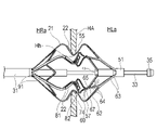
- the number of first struts 63 is one-fourth that of the embodiment shown in FIGS.
- the number of (buffer portions) may be 1/4 or six.
- Each of the six second struts 64 branched from the three first struts 63 is connected to each of the six auxiliary bending portions 67 (buffer portions) without gathering. Note that the auxiliary curved portion 67 may not be provided between the second strut 64 and the facing portion 82 .
- the first strut 63 is arranged in a different phase than the third strut 91 , the energy transfer element arrangement portion 81 , the facing portion 82 and the energy transfer element 22 .
- step S4 of expanding the diameter of the through hole Hh with the expander 21 or gripping the through hole Hh with the expander 21 and the step S5 of checking the hemodynamics in the vicinity of the through hole Hh may be reversed. good.
- the operator moves the outer tube 30 toward the distal end side and accommodates the expansion body 21 in the outer tube 30.
- the expansion body 21 is pulled out from the through hole Hh together with the outer cylinder 30 .
- the through-hole Hh is expanded again using a balloon catheter having a balloon with an expansion diameter larger than that of the balloon 252 used in step S1, and the process returns to step S2.
Abstract
In order to provide a medical device and a shunt formation method with which susceptibility to the effects of variations in the thickness of biological tissue is reduced, excess expansion of a hole in the biological tissue is inhibited, and suitable and highly safe cauterization is made possible, the present invention is provided with an expansion body (21), an elongated shaft part (31) to which the base end of the expansion body is fixed, a plurality of energy transmission elements (22) disposed along the expansion body, and a traction shaft (33). The traction shaft is configured to slide against the shaft part (31) in the base end direction to apply, through a force-receiving part (51) to the expansion body, a compressive force that applies a compression along the axis of the shaft part so that a plurality of energy transmission element disposition parts (81) and a plurality of facing parts (82) approach each other. The expansion body has buffer parts (64) that are disposed in a first expansion part (53) and that are configured to deform in a direction different to the direction heading from the force-receiving part to a distal-end-side top part (57) along a distal-end-side expansion part (56), and thereby relieve the compressive force.
Description
本発明は、生体内で拡張させる拡張体を備えた医療デバイスおよびシャント形成方法に関する。
The present invention relates to a medical device and a shunt forming method with an expandable body that expands in vivo.
心臓疾患の一つとして、慢性心不全が知られている。慢性心不全は、心機能の指標に基づいて収縮不全と拡張不全に大別される。拡張不全に罹患した患者は、心筋が肥大化してスティッフネス(硬さ)が増すことで、左心房の血圧が高まり、心臓のポンプ機能が低下する。これにより、患者は、肺水腫などの心不全症状を呈することとなる。また、肺高血圧症等により右心房側の血圧が高まり、心臓のポンプ機能が低下することで心不全症状を呈するような心臓疾患もある。
Chronic heart failure is known as one of the heart diseases. Chronic heart failure is broadly classified into systolic and diastolic failure based on indicators of cardiac function. Patients with diastolic insufficiency have enlarged and stiffened myocardium, which increases pressure in the left atrium and reduces the heart's ability to pump. This causes the patient to present symptoms of heart failure such as pulmonary edema. In addition, there is also a heart disease in which pulmonary hypertension or the like causes the blood pressure in the right atrium to rise and the pumping function of the heart to decline, resulting in symptoms of heart failure.
近年、これらの心不全患者に対し、上昇した心房圧の逃げ道となるシャント(貫通孔)を心房中隔に形成し、心不全症状の緩和を可能にするシャント治療が注目されている。シャント治療は、経静脈アプローチで心房中隔にアクセスし、所望のサイズの貫通孔を形成する。このような心房中隔に対するシャント治療を行うための医療デバイスとして、例えば特許文献1に挙げるようなものがある。
In recent years, attention has been focused on shunt therapy, which forms a shunt (through-hole) in the interatrial septum that serves as an escape route for elevated atrial pressure in these patients with heart failure, enabling alleviation of heart failure symptoms. Shunt therapy accesses the atrial septum via a transvenous approach to create a through hole of the desired size. As a medical device for performing such a shunt treatment for the interatrial septum, there is, for example, a device as described in Patent Document 1.
特許文献1に記載の医療デバイスは、長尺なシャフトの軸を中心に拡張可能な2つの拡張体により、生体組織を先端側および基端側から挟み、一方の拡張体の周方向に並ぶ複数のエネルギー伝達要素である電極部を、治療対象の生体組織の孔の周方向に並ぶように生体組織に対して接触させた後に、複数の電極部からエネルギーを付与して生体組織を焼灼している。
The medical device described in Patent Document 1 sandwiches a living tissue from the distal end side and the proximal end side by two expandable bodies that are expandable around the axis of a long shaft, and one of the expanders is aligned in the circumferential direction. After contacting the biological tissue so as to be aligned in the circumferential direction of the hole of the biological tissue to be treated, energy is applied from the plurality of electrode units to cauterize the biological tissue. there is
電極を組織に押し当てるために組織を把持する際、組織の厚みによって、牽引シャフトによる拡張体の圧縮力が大きく変動してしまう。組織が厚い場合には、想定よりも大きい圧縮力が電極にかかるため、想定以上に生体組織の孔を拡張させてしまう恐れがある。
When grasping the tissue to press the electrode against the tissue, the compression force of the extension body by the traction shaft fluctuates greatly depending on the thickness of the tissue. When the tissue is thick, the electrodes are subjected to a larger compressive force than expected, which may cause the pores of the living tissue to expand more than expected.
本発明は、上述した課題を解決するためになされたものであり、生体組織の厚みのバラツキから影響を受けにくくなり、生体組織の孔を拡張しすぎることを抑制して、安全性の高い適切な焼灼を可能とする医療デバイスおよびシャント形成方法を提供することを目的とする。
The present invention has been made to solve the above-described problems. An object of the present invention is to provide a medical device and a method for forming a shunt that enable easy cauterization.
上記目的を達成する本発明に係る医療デバイスは、受力部を含む先端部を有する径方向に拡縮可能な拡張体と、前記拡張体の基端が固定された先端部を有する長尺なシャフト部と、前記拡張体に沿って設けられる複数のエネルギー伝達要素と、前記シャフト部の内部に配置されるとともに、前記シャフト部の前記先端部から突出して前記拡張体の前記受力部に接続可能であり、前記シャフト部に対して摺動可能な牽引シャフトと、備え、前記拡張体は、前記受力部から基端方向に向かって径方向外側に延びる先端側拡張部と、前記先端側拡張部の基端側に配置され径方向外向きの凸状に湾曲した先端側頂部と、を含む第1拡張部と、前記シャフト部の前記先端部から先端方向に向かって径方向外側に延びる基端側拡張部と、前記基端側拡張部の先端側に配置され径方向外向きの凸状に湾曲した基端側頂部と、を含む第2拡張部と、径方向内側に窪み、かつ、前記基端側頂部と前記先端側頂部とを連結するように延び、前記拡張体の拡張時に生体組織を受容可能な受容空間を画成する凹部と、を有し、前記凹部は、径方向の最も内側に位置する底部と、前記底部の先端から前記先端側頂部まで径方向外側に延びる先端側起立部と、前記底部の基端から前記基端側頂部まで径方向外側に延びる基端側起立部と、有し、前記先端側起立部と前記基端側起立部のいずれかは、前記拡張体の周方向に略等間隔に、前記複数のエネルギー伝達要素のそれぞれが配置される複数のエネルギー伝達要素配置部を有し、前記先端側起立部と前記基端側起立部の他方は、前記拡張体の拡張時に前記複数のエネルギー伝達要素のそれぞれと対向する複数の対向部を有し、前記牽引シャフトは、前記シャフト部に対して基端方向に摺動することにより、前記複数のエネルギー伝達要素配置部と前記複数の対向部とが近づくように前記シャフト部の軸心に沿って圧縮する圧縮力を、前記受力部を介して前記拡張体に及ぼすように構成されており、前記拡張体は、前記第1拡張部に配置され、前記先端側拡張部に沿って前記受力部から前記先端側頂部に向かう方向とは異なる方向に変形することで前記圧縮力を緩和するように構成された緩衝部、または、前記第2拡張部に配置され、前記基端側拡張部に沿って前記拡張体の前記基端から前記基端側頂部に向かう方向とは異なる方向に変形することで前記圧縮力を緩和するように構成された緩衝部を有する。
A medical device according to the present invention for achieving the above object is a radially expandable and contractible expandable body having a distal end portion including a force receiving portion, and an elongated shaft having a distal end portion to which the proximal end of the expandable body is fixed. and a plurality of energy transmission elements provided along the extension body, disposed within the shaft section and protruding from the distal end of the shaft section and connectable to the force receiving section of the extension body. a traction shaft slidable with respect to the shaft portion; a radially outwardly convexly curved distal apex located proximally of the shaft portion; a second extension that includes an end extension and a proximal apex that is disposed on the distal side of the proximal extension and is curved in a radially outward convex shape; is recessed radially inward; a recess extending so as to connect the proximal side apex and the distal side apex and defining a receiving space capable of receiving living tissue when the expander is expanded, the recess extending in the radial direction. an innermost bottom, a distal upright extending radially outward from a tip of the bottom to the distal apex, and a proximal upright extending radially outward from a proximal end of the bottom to the proximal apex. and a plurality of energy transmission elements, each of which is arranged at approximately equal intervals in the circumferential direction of the expandable body, in either the distal side upright portion or the proximal side upright portion. a transmission element placement portion, wherein the other of the distal side upright portion and the proximal side upright portion has a plurality of opposing portions that face each of the plurality of energy transmission elements when the expansion body is expanded; The traction shaft compresses along the axis of the shaft portion by sliding in the proximal direction with respect to the shaft portion so that the plurality of energy transmission element placement portions and the plurality of opposing portions approach each other. A compressive force is configured to exert a compressive force on the expander via the force-receiving portion, the expander being disposed on the first extension and extending from the force-receiving portion along the distal extension. A buffer configured to relieve the compressive force by deforming in a direction different from the direction toward the distal apex; or a buffer located on the second extension and along the proximal extension. It has a cushioning part configured to relieve the compressive force by deforming in a direction different from the direction from the proximal end of the expansion body to the proximal top part. be.
上記目的を達成する本発明に係るシャント形成方法は、受力部を含む先端部を有する径方向に拡縮可能な拡張体と、前記拡張体の基端が固定された先端部を有する長尺なシャフト部と、前記拡張体に沿って設けられる複数のエネルギー伝達要素と、前記シャフト部の内部に配置されるとともに、前記シャフト部の前記先端部から突出して前記拡張体の前記受力部に接続可能であり、前記シャフト部に対して摺動可能な牽引シャフトと、備え、前記拡張体は、前記受力部から基端方向に向かって径方向外側に延びる先端側拡張部と、前記先端側拡張部の基端側に配置され径方向外向きの凸状に湾曲した先端側頂部と、を含む第1拡張部と、前記シャフト部の前記先端部から先端方向に向かって径方向外側に延びる基端側拡張部と、前記基端側拡張部の先端側に配置され径方向外向きの凸状に湾曲した基端側頂部と、を含む第2拡張部と、径方向内側に窪み、かつ、前記基端側頂部と前記先端側頂部とを連結するように延び、前記拡張体の拡張時に生体組織を受容可能な受容空間を画成する凹部と、を有し、前記凹部は、径方向の最も内側に位置する底部と、前記底部の先端から前記先端側頂部まで径方向外側に延びる先端側起立部と、前記底部の基端から前記基端側頂部まで径方向外側に延びる基端側起立部と、有し、前記先端側起立部と前記基端側起立部のいずれかは、前記拡張体の周方向に略等間隔に、前記複数のエネルギー伝達要素のそれぞれが配置される複数のエネルギー伝達要素配置部を有し、前記先端側起立部と前記基端側起立部の他方は、前記拡張体の拡張時に前記複数のエネルギー伝達要素のそれぞれと対向する複数の対向部を有し、前記牽引シャフトは、前記シャフト部に対して基端方向に摺動することにより、前記複数のエネルギー伝達要素配置部と前記複数の対向部とが近づくように前記シャフト部の軸心に沿って圧縮する圧縮力を、前記受力部を介して前記拡張体に及ぼすように構成されており、前記拡張体は、前記第1拡張部に配置され、前記先端側拡張部に沿って前記受力部から前記先端側頂部に向かう方向とは異なる方向に変形することで前記圧縮力を緩和するように構成された緩衝部、または、前記第2拡張部に配置され、前記基端側拡張部に沿って前記拡張体の前記基端から前記基端側頂部に向かう方向とは異なる方向に変形することで前記圧縮力を緩和するように構成された緩衝部を有する医療デバイスを用いて卵円窩に右心房と左心房を連通するシャントを形成するシャント形成方法であって、前記医療デバイスを下大静脈から前記右心房内に挿入し、前記卵円窩に形成した孔に収縮した前記拡張体を挿入し、前記孔内で前記拡張体を拡張させて、前記凹部により画成される受容空間に、前記孔を取り囲む生体組織を配置し、前記牽引シャフトを前記シャフト部に対して基端方向に摺動することにより、前記凹部の前記先端側起立部と前記基端側起立部とが互いに近づくように前記拡張体が圧縮され、前記先端側拡張部に沿って前記受力部から前記先端側頂部に向かう方向とは異なる方向に前記緩衝部を変形させることで前記圧縮力を緩和させ、または、前記第2拡張部に配置され、前記基端側拡張部に沿って前記拡張体の前記基端から前記基端側頂部に向かう方向とは異なる方向に前記緩衝部を変形させることで前記圧縮力を緩和させつつ、前記凹部の前記先端側起立部または前記基端側起立部に沿って前記凹部に面するように配置された前記エネルギー伝達要素を前記生体組織に密着させ、前記孔の自然治癒による閉塞を阻害するように、前記生体組織に密着した前記エネルギー伝達要素を用いて前記受容空間に配置された前記生体組織を焼灼する。
A method of forming a shunt according to the present invention for achieving the above object is to provide an elongated body having a radially expandable and retractable expandable body having a distal end portion including a force receiving portion and a distal end portion to which the proximal end of the expandable body is fixed. a shaft portion, a plurality of energy transmission elements provided along the extension body, disposed inside the shaft portion and projecting from the distal end portion of the shaft portion and connected to the force receiving portion of the extension body. a traction shaft slidable relative to the shaft portion, wherein the extension body includes a distal extension portion extending radially outward from the force receiving portion toward a proximal direction; a radially outwardly convexly curved distal apex located proximally of the extension; and extending radially outwardly in a distal direction from the distal end of the shaft portion. a second extension that includes a proximal extension and a proximal apex that is disposed on the distal side of the proximal extension and is curved in a radially outward convex shape; is recessed radially inward; and a concave portion extending to connect the proximal side top portion and the distal side top portion and defining a receiving space capable of receiving living tissue when the expansion body is expanded, the concave portion extending radially. a bottom portion located on the innermost side of the bottom portion, a distal side upright portion extending radially outward from the tip of the bottom portion to the distal side top portion, and a proximal side extending radially outwardly from the base end of the bottom portion to the proximal side top portion a standing portion, wherein either the distal side standing portion or the proximal side standing portion includes a plurality of energy transmission elements arranged at approximately equal intervals in the circumferential direction of the expandable body. an energy transmission element placement portion, wherein the other of the distal side upright portion and the proximal side upright portion has a plurality of facing portions that face each of the plurality of energy transmission elements when the expansion body is expanded; The traction shaft is compressed along the axis of the shaft portion by sliding in the proximal direction with respect to the shaft portion so that the plurality of energy transmission element placement portions and the plurality of opposing portions approach each other. is configured to exert a compressive force on the expander via the force receiving portion, the expander being disposed on the first extension and extending along the distal extension along the force receiving portion. a buffer configured to relieve the compressive force by deforming in a direction different from the direction toward the distal apex; a cushioning portion configured to alleviate the compressive force by deforming in a direction different from the direction from the base end of the expansion body toward the base end side top portion by A shunt forming method for forming a shunt connecting the right atrium and the left atrium in the fossa ovalis using a medical device having a inserting the contracted expandable body into the formed hole, expanding the expandable body within the hole, placing the living tissue surrounding the hole in the receiving space defined by the recess, and pulling the traction shaft; By sliding in the proximal direction with respect to the shaft portion, the expansion body is compressed so that the distal-side upright portion and the proximal-side upright portion of the recess are brought closer to each other, and the distal-side expansion portion is compressed. The compressive force is relieved by deforming the cushioning portion in a direction different from the direction from the force receiving portion toward the tip side apex along the direction, or the compression force is relieved by the second extension portion and the proximal side extension While relaxing the compressive force by deforming the cushioning portion in a direction different from the direction from the proximal end of the expansion body to the proximal top portion along the portion, the distal side upright portion of the recess or The energy transmission element, which is arranged along the proximal upright portion so as to face the concave portion, is brought into close contact with the living tissue so as to inhibit closure of the hole due to natural healing. The energy delivery element is used to ablate the biological tissue located in the receiving space.
上記のように構成した医療デバイスおよびシャント形成方法は、牽引シャフトの牽引によって拡張体に圧縮力が作用する際に、受力部から先端側頂部に向かう方向とは異なる方向、または拡張体の基端から基端側頂部に向かう方向とは異なる方向に緩衝部が変形することで圧縮力が緩和されるため、拡張体が径方向外側へ拡張しすぎることを抑制できる。したがって、受容空間に受容する生体組織が厚い場合と薄い場合での拡張体の径方向外側への拡張量の変動を抑制できる。このため、本医療デバイスおよびシャント形成方法は、生体組織の厚みのバラツキから影響を受けにくくなり、生体組織の孔を拡張しすぎることを抑制して、安全性の高い適切な焼灼を可能とする。
In the medical device and shunt forming method configured as described above, when a compressive force acts on the expandable body due to the traction of the traction shaft, the direction different from the direction from the force-receiving portion toward the top of the distal side or the base of the expandable body is applied. Since the compressive force is relieved by the deformation of the cushioning portion in a direction different from the direction from the end toward the base end side top portion, it is possible to suppress the expansion body from expanding excessively radially outward. Therefore, it is possible to suppress variation in the radially outward expansion amount of the expansion body depending on whether the biological tissue received in the receiving space is thick or thin. Therefore, the present medical device and shunt forming method are less likely to be affected by variations in the thickness of the living tissue, suppressing excessive expansion of the pores of the living tissue, and enabling highly safe and appropriate cauterization. .
前記第1拡張部は、前記受力部から基端方向に向かって径方向外側に延び、前記先端側拡張部を形成する複数の先端側ストラット構造を有し、前記複数の先端側ストラット構造はそれぞれ、各先端側ストラット構造に沿って前記受力部から前記先端側頂部に向かう方向とは異なる方向に湾曲可能な湾曲部を前記緩衝部として有してもよい。これにより、緩衝部を単純な構造で実現できる。
The first extension portion has a plurality of distal strut structures extending radially outward from the force receiving portion in a proximal direction to form the distal extension portion, wherein the plurality of distal strut structures comprises: Each may have a bending portion as the cushioning portion that can bend in a direction different from the direction from the force-receiving portion toward the tip-side apex along each tip-side strut structure. As a result, the buffer section can be realized with a simple structure.
前記複数の先端側ストラット構造はそれぞれ、径方向の外側から見て前記拡張体の前記軸心に略平行に前記受力部から延びる第1ストラットを含む第1セクションと、前記第1セクションの基端から前記拡張体の周方向に略沿うように二股に分岐した2つの第2ストラットを含み、前記先端側頂部に連結した第2セクションと、を有し、前記第2セクションは、分岐している前記2つの第2ストラットのなす分岐角度が増すように湾曲することで前記圧縮力を緩和する前記緩衝部として機能してもよい。これにより、先端側ストラット構造の第2セクションは、分岐している2つの第2ストラットのなす分岐角度が増すように湾曲することで、圧縮力を緩和させて、拡張体が径方向外側へ拡張しすぎることを抑制できる。
each of the plurality of distal strut structures includes a first section including a first strut extending from the force receiving portion substantially parallel to the axis of the expander when viewed from the radially outer side; and a base of the first section. a second section including two second struts bifurcated from an end generally along the circumferential direction of the extension body and connected to the distal top, wherein the second section is bifurcated; The second strut may function as the cushioning portion that relaxes the compressive force by bending so as to increase the branching angle formed by the two second struts. As a result, the second section of the distal strut structure is curved so as to increase the branch angle formed by the two branched second struts, thereby relieving the compressive force and expanding the expansion body radially outward. You can restrain yourself from doing too much.
前記第2セクションは、前記先端側頂部近傍において、前記2つの第2ストラットのそれぞれが周方向に隣接する他の前記第2セクションの前記2つの第2ストラットの一方と合流する複数の合流部を有してもよい。これにより、拡張体は、隣接する先端側ストラット構造同士が周方向に互いに支え合う形態となるため、拡張時に捩じれ難くなる。
The second section has a plurality of confluences where each of the two second struts merges with one of the two second struts of the other second section adjacent in the circumferential direction in the vicinity of the top on the tip side. may have. As a result, the expandable body has a form in which the adjacent distal strut structures support each other in the circumferential direction, so that it is difficult to twist during expansion.
前記第2セクションは、前記エネルギー伝達要素配置部または前記対向部と前記拡張体の周方向において同一位相に配置された前記先端側頂部と前記複数の合流部との間に、前記緩衝部として機能する補助湾曲部を有してもよい。これにより、補助湾曲部が変形することで、圧縮力をさらに緩和させることができるため、圧縮力が拡張力へ、より変換され難くなる。
The second section functions as the buffer portion between the energy transmission element arrangement portion or the facing portion and the tip side top portion and the plurality of confluence portions arranged in the same phase in the circumferential direction of the expansion body. It may have an auxiliary curved portion for As a result, the compressive force can be further reduced by deforming the auxiliary bending portion, so that the compressive force is less likely to be converted into the expansive force.
前記複数の先端側ストラット構造は、前記複数のエネルギー伝達要素の2倍の数の前記第1セクション及び前記合流部を有し、前記合流部は、前記拡張体の周方向において、前記複数のエネルギー伝達要素配置部および前記複数の対向部と同一位相に配置された第1合流部と、前記複数のエネルギー伝達要素配置部および前記複数の対向部とは異なる位相に配置された第2合流部とを、交互に有してもよい。これにより、拡張体は、隣接する先端側ストラット構造同士が周方向に互いに支え合う形態となるため、拡張時に捩じれ難くなる。
The plurality of distal strut structures has twice as many of the first sections and the junctions as the plurality of energy transmission elements, wherein the junctions are circumferentially spaced from the plurality of energy a first merging portion arranged in the same phase as the transfer element arrangement portion and the plurality of opposing portions; and a second merging portion arranged in a phase different from the plurality of energy transfer element arrangement portions and the plurality of opposing portions. , alternately. As a result, the expandable body has a form in which the adjacent distal strut structures support each other in the circumferential direction, so that it is difficult to twist during expansion.
前記第1合流部と前記先端側頂部との間に、前記緩衝部として機能する補助湾曲部を有してもよい。これにより、補助湾曲部が変形することで、圧縮力をさらに緩和させることができるため、圧縮力が拡張力へ、より変換され難くなる。
An auxiliary curved portion functioning as the cushioning portion may be provided between the first confluence portion and the top portion on the distal end side. As a result, the compressive force can be further reduced by deforming the auxiliary bending portion, so that the compressive force is less likely to be converted into the expansive force.
前記凹部は、前記先端側ストラット構造に対して前記先端側頂部を介して連結し、前記先端側起立部、前記基端側起立部及び前記底部を画成する凹型ストラット構造を有し、前記凹型ストラット構造は、前記底部に、前記複数のエネルギー伝達要素配置部と前記複数の対向部のそれぞれの対を連結する複数の底部連結部を有し、前記複数の底部連結部は、前記拡張体の周方向において、前記第1ストラットとは異なる位相に配置されてもよい。これにより、異なる位相に配置される底部連結部と第1ストラットとの間に、周方向へ延びる部位が存在することになるため、分岐角度を広げる方向に力が作用しやすくなり、圧縮力が拡張力に変換され難くなる。
The recess has a recessed strut structure connected to the distal strut structure via the distal apex and defining the distal upstand, the proximal upstand and the bottom; The strut structure has a plurality of bottom connections on the bottom portion connecting respective pairs of the plurality of energy transfer element locations and the plurality of opposing portions, the plurality of bottom connections being connected to the extension body. In the circumferential direction, the struts may be arranged in phases different from those of the first struts. As a result, since there is a portion extending in the circumferential direction between the bottom connecting portion and the first strut, which are arranged in different phases, a force tends to act in the direction of widening the branching angle, and the compressive force is reduced. It becomes difficult to convert into expansion power.
前記エネルギー伝達要素配置部は、前記基端側起立部に設けられており、前記緩衝部は、前記先端側拡張部にのみ設けられてもよい。これにより、拡張体の圧縮時に、エネルギー伝達要素を組織に確実に押し当てることができる。
The energy transmission element placement portion may be provided on the proximal side upright portion, and the buffer portion may be provided only on the distal side extended portion. This ensures that the energy transmission element presses against the tissue when the expander is compressed.
前記第2拡張部は、前記シャフト部の前記先端部から先端方向に向かって径方向外側に延び、前記基端側拡張部を形成する複数の基端側ストラット構造を有し、前記複数の基端側ストラット構造はそれぞれ、前記複数のエネルギー伝達要素配置部と前記拡張体の周方向において同一位相に配置され、径方向の外側から見て前記拡張体の前記軸心に略平行に前記シャフト部の前記先端部から前記基端側頂部まで延びる第3ストラットを有してもよい。これにより、拡張体の圧縮時に、エネルギー伝達要素を組織に確実に押し当てることができる。
The second extension has a plurality of proximal strut structures extending radially outwardly in a distal direction from the distal end of the shaft portion to form the proximal extension; Each of the end strut structures is arranged in the same phase in the circumferential direction of the plurality of energy transmission element arrangement portions and the expansion body, and substantially parallel to the axis of the expansion body when viewed from the radial outside. There may be a third strut extending from the distal end of the to the proximal apex. This ensures that the energy transmission element presses against the tissue when the expander is compressed.
前記第2拡張部は、前記複数の基端側ストラット構造のうち周方向に隣接する前記第3ストラット同士を連結する複数の副ストラットを有し、前記複数の副ストラットはそれぞれ、前記複数の第3ストラットのうち周方向に隣接する2つの第3ストラットの各々に接合される2つの接合部を有する少なくとも1つの支持ストラットを有し、前記複数の支持ストラットはそれぞれ、2つの前記接合部の間の直線距離よりも長く形成されてもよい。これにより、圧縮力を受けた基端側ストラット構造が、エネルギー伝達要素を組織へ押し当てる際に周方向へ捩れることを、支持ストラットにより抑制できる。このため、医療デバイスは、エネルギー伝達要素を組織へ押し当てる力が分散しにくくなり、エネルギー伝達要素を生体組織へ効果的に押し当てることができる。
The second extension part has a plurality of secondary struts that connect the circumferentially adjacent third struts among the plurality of proximal strut structures, and the plurality of secondary struts are each connected to the plurality of third struts. at least one support strut having two joints joined to each of two circumferentially adjacent third struts of the three struts, each of said plurality of support struts being between two said joints; may be formed longer than the linear distance of Thus, the support struts can prevent the proximal strut structure, which receives the compressive force, from twisting in the circumferential direction when the energy transmission element is pressed against the tissue. Therefore, in the medical device, the force of pressing the energy transmission element against the tissue is less dispersed, and the energy transmission element can be effectively pressed against the living tissue.
前記第2拡張部は、前記シャフト部の前記先端部から先端方向に向かって径方向外側に延び、前記基端側拡張部を形成する複数の基端側ストラット構造を有し、前記複数の基端側ストラット構造はそれぞれ、径方向の外側から見て前記拡張体の前記軸心に略平行に前記シャフト部の前記先端部から延びる第3ストラットを含む第3セクションと、前記第3セクションの先端から前記拡張体の周方向に略沿うように二股に分岐した2つの第4ストラットを含み、前記基端側頂部に連結した第4セクションと、を有し、前記第4セクションは、分岐している前記2つの第4ストラットのなす分岐角度が増すように湾曲することで前記圧縮力を緩和する前記緩衝部として機能してもよい。基端側ストラット構造の第4セクションは、分岐している2つの第4ストラットのなす分岐角度が増すように湾曲することで、圧縮力を緩和させて、拡張体が径方向外側へ拡張しすぎることを抑制できる。
The second extension has a plurality of proximal strut structures extending radially outwardly in a distal direction from the distal end of the shaft portion to form the proximal extension; The end strut structures each include a third section including a third strut extending from the distal end of the shaft portion substantially parallel to the axis of the extension when viewed radially outwardly, and a distal end of the third section. a fourth section including two fourth struts bifurcated substantially along the circumferential direction of the expander from and connected to the proximal apex, wherein the fourth section bifurcates from It may function as the cushioning portion that relieves the compressive force by curving such that the branching angle formed by the two fourth struts that are present increases. The fourth section of the proximal strut structure is curved to increase the bifurcation angle between the two bifurcated fourth struts, thereby relieving the compressive force and preventing the expansion body from expanding too radially outward. can be suppressed.
前記第4セクションは、前記基端側頂部近傍において、前記2つの第4ストラットのそれぞれが周方向に隣接する他の前記第4セクションの前記2つの第4ストラットの一方と合流する複数の合流部を有してもよい。これにより、拡張体は、隣接する基端側ストラット構造0同士が周方向に互いに支え合う形態となるため、拡張時に捩じれ難くなる。このため、拡張体によって生体組織の適切な位置を適切に拡張させて、適切な焼灼が可能となる。
The fourth section has a plurality of confluence portions where each of the two fourth struts merges with one of the two fourth struts of the other circumferentially adjacent fourth section near the top portion on the proximal side. may have As a result, the expansion body takes a form in which the adjacent base end strut structures 0 support each other in the circumferential direction, so that it is difficult to twist during expansion. For this reason, the expandable body can appropriately expand the appropriate position of the living tissue to perform appropriate cauterization.
以下、図面を参照して、本発明の実施の形態を説明する。なお、図面の寸法比率は、説明の都合上、誇張されて実際の比率とは異なる場合がある。また、本明細書では、医療デバイスの生体内腔に挿入する側を「先端側」、操作する側を「基端側」と称することとする。
Hereinafter, embodiments of the present invention will be described with reference to the drawings. Note that the dimensional ratios in the drawings may be exaggerated for convenience of explanation and may differ from the actual ratios. Also, in this specification, the side of a medical device that is inserted into a living body cavity is referred to as the "distal side", and the side that is operated is referred to as the "proximal side".
本実施形態に係る医療デバイス10は、図5に示すように、患者の心臓Hの心房中隔HAに形成された貫通孔Hhを拡張し、さらに拡張した貫通孔Hhをその大きさに維持する維持処置を行うことができるように構成されている。
As shown in FIG. 5, the medical device 10 according to this embodiment expands the through hole Hh formed in the interatrial septum HA of the patient's heart H and maintains the expanded through hole Hh at that size. It is configured so that maintenance treatment can be performed.
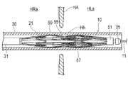
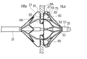
図1に示すように、本実施形態に係る医療デバイス10は、基端から先端へ延在する長尺部20と、長尺部20の先端部に設けられる拡張体21と、長尺部20の基端部に接続される操作部23とを有している。拡張体21には、前述の維持処置を行うためのエネルギー伝達要素22(電極部)が設けられる。
As shown in FIG. 1, the medical device 10 according to the present embodiment includes a long portion 20 extending from the proximal end to the distal end, an extension body 21 provided at the distal end of the long portion 20, and the long portion 20 and an operation portion 23 connected to the proximal end portion of the. The extension body 21 is provided with an energy transmission element 22 (electrode portion) for performing the aforementioned maintenance procedure.
長尺部20は、図1~3に示すように、先端部に拡張体21を保持しているシャフト部31と、シャフト部31を収納する外筒30と、牽引シャフト33と、牽引シャフト33の先端に固定される牽引部35とを有している。
As shown in FIGS. 1 to 3, the elongated portion 20 includes a shaft portion 31 holding the expansion body 21 at the distal end portion, an outer cylinder 30 housing the shaft portion 31, a traction shaft 33, and a traction shaft 33. It has a traction part 35 fixed to the tip of the.
シャフト部31は、操作部23から拡張体21まで延在する長尺な管体である。シャフト部31の基端部は、操作部23の先端部に固定されている。シャフト部31の先端部は、拡張体21の基端部に固定されている。
The shaft portion 31 is an elongate tubular body extending from the operating portion 23 to the extension body 21 . A proximal end portion of the shaft portion 31 is fixed to a distal end portion of the operation portion 23 . A distal end portion of the shaft portion 31 is fixed to a proximal end portion of the extension body 21 .
外筒30は、シャフト部31を覆う長尺な管体であり、シャフト部31に対して軸方向(長尺部20の軸心の方向)に進退移動可能である。外筒30は、長尺部20の先端側に移動した状態で、その内部に収縮させた拡張体21を収納することができる。拡張体21を収納した状態から、外筒30を基端側に移動させることで、拡張体21を露出させることができる。
The outer cylinder 30 is a long tubular body that covers the shaft portion 31, and can move back and forth with respect to the shaft portion 31 in the axial direction (in the direction of the axis of the long portion 20). The outer cylinder 30 can accommodate the contracted expansion body 21 in the interior thereof in a state of being moved to the distal end side of the elongated portion 20 . The expansion body 21 can be exposed by moving the outer cylinder 30 toward the base end side from the state in which the expansion body 21 is stored.
牽引シャフト33は、シャフト部31の内部に配置される長尺な管体であり、シャフト部31に対して軸方向に進退移動可能である。牽引シャフト33は、シャフト部31の先端から先端側に突出するとともに、拡張体21の先端から先端側に突出している。牽引シャフト33の拡張体21よりも先端側に位置する先端部は、牽引部35に固定されている。牽引シャフト33の基端部は、操作部23より基端側に導出されている。牽引シャフト33の内部には、軸方向に沿ってガイドワイヤルーメンが形成されており、ガイドワイヤ11(図5~7を参照)を挿通させることができる。
The traction shaft 33 is an elongated tubular body arranged inside the shaft portion 31 and is axially movable forward and backward with respect to the shaft portion 31 . The traction shaft 33 protrudes distally from the distal end of the shaft portion 31 and protrudes distally from the distal end of the extension body 21 . A distal end portion of the pulling shaft 33 located on the distal side of the extension body 21 is fixed to the pulling portion 35 . A proximal end portion of the traction shaft 33 is led out from the operation portion 23 to the proximal end side. A guide wire lumen is formed along the axial direction inside the pulling shaft 33, through which the guide wire 11 (see FIGS. 5 to 7) can be passed.
牽引部35は、牽引シャフト33の先端部の外周面に固定される環状の部材であり、牽引シャフト33の外周面から径方向の外側へ突出している。牽引部35は、拡張体21には固定されていない。牽引部35の外径は、拡張体21の先端部の内径よりも大きい。このため、牽引部35は、拡張体21の先端部に先端側から当接し、拡張体21を基端方向へ牽引して、シャフト部31の軸方向に沿って圧縮する圧縮力を拡張体21に作用させることができる。
The pulling part 35 is an annular member fixed to the outer peripheral surface of the leading end of the pulling shaft 33 and protrudes radially outward from the outer peripheral surface of the pulling shaft 33 . The traction part 35 is not fixed to the extension body 21 . The outer diameter of the pulling part 35 is larger than the inner diameter of the distal end of the expansion body 21 . Therefore, the pulling portion 35 abuts on the distal end portion of the expandable body 21 from the distal end side, pulls the expandable body 21 in the proximal direction, and applies a compressive force compressing the shaft portion 31 along the axial direction to the expandable body 21 . can act on
操作部23は、術者が把持するハウジング40と、術者が回転操作可能なダイヤル41と、ダイヤル41の回転を軸方向の移動に変換する変換機構42とを有している。ダイヤル41は、ハウジング40に対して回転可能に連結されている。ダイヤル41の一部は、術者が操作できるように、ハウジング40の開口から外部へ露出されている。牽引シャフト33は、操作部23の内部において、変換機構42に保持されている。変換機構42は、ダイヤル41の回転に伴い、保持する牽引シャフト33を軸方向に沿って進退移動させることができる。変換機構42としては、例えばラックピニオン機構を用いることができる。
The operation unit 23 has a housing 40 gripped by the operator, a dial 41 that can be rotated by the operator, and a conversion mechanism 42 that converts rotation of the dial 41 into axial movement. Dial 41 is rotatably connected to housing 40 . A part of the dial 41 is exposed to the outside through the opening of the housing 40 so that the operator can operate it. The traction shaft 33 is held by the conversion mechanism 42 inside the operation portion 23 . As the dial 41 rotates, the conversion mechanism 42 can axially move the pulling shaft 33 it holds back and forth. As the conversion mechanism 42, for example, a rack and pinion mechanism can be used.
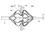
拡張体21は、図2~4に示すように、拡張体21の先端に配置される受力部51と、拡張体21の基端に配置される基端連結部52と、受力部51に連結される第1拡張部53と、基端連結部52に連結される第2拡張部54と、第1拡張部53および第2拡張部54の間に配置される凹部55とを有している。
2 to 4, the expandable body 21 includes a force receiving portion 51 arranged at the distal end of the expandable body 21, a base end connecting portion 52 arranged at the proximal end of the expandable body 21, and the force receiving portion 51. , a second extension 54 connected to the proximal connection 52, and a recess 55 disposed between the first extension 53 and the second extension 54. ing.
受力部51は、環状であり、先端側に配置される牽引部35から基端方向へ向かう力を受けることができる。基端連結部52は、環状であり、シャフト部31の先端部に固定されている。
The force receiving portion 51 has an annular shape and can receive a force directed toward the proximal direction from the traction portion 35 arranged on the distal side. The base end connecting portion 52 has an annular shape and is fixed to the distal end portion of the shaft portion 31 .
第1拡張部53は、受力部51から基端方向に向かって径方向外側に延びる先端側拡張部56と、先端側拡張部56の基端側に配置され径方向外向きの凸状に湾曲した先端側頂部57とを有している。
The first extended portion 53 includes a distal extended portion 56 extending radially outward from the force receiving portion 51 toward the proximal direction, and a distal extended portion 56 arranged on the proximal side of the distal extended portion 56 and protruding radially outward. It has a curved distal apex 57 .
第1拡張部53は、受力部51から基端方向に向かって径方向外側に延び、先端側拡張部56を形成する複数の先端側ストラット構造60を有する。
The first extension portion 53 has a plurality of distal strut structures 60 extending radially outward from the force receiving portion 51 toward the proximal direction to form distal extension portions 56 .
複数の先端側ストラット構造60はそれぞれ、受力部51から基端方向に向かって延びる第1セクション61と、第1セクション61の基端から基端方向に向かって延びて先端側頂部57に連結される第2セクション62とを有する。
The plurality of distal strut structures 60 each include a first section 61 extending proximally from the force receiving portion 51 and a distal apex 57 extending proximally from the proximal end of the first section 61 . and a second section 62 that is
それぞれの第1セクション61は、径方向の外側から見て拡張体21の軸心に略平行に受力部51から延びる第1ストラット63を有する。
Each first section 61 has a first strut 63 extending from the force receiving portion 51 substantially parallel to the axis of the extension body 21 when viewed from the radially outer side.
それぞれの第2セクション62は、それぞれの第1ストラット63の基端から基端方向へ向かいつつ拡張体21の周方向へ広がるように二股に分岐した複数の第2ストラット64と、第2ストラット64の基端に連結される第1合流部65および第2合流部66と、緩衝部として機能する補助湾曲部67とを有する。第1合流部65および第2合流部66は、ほぼ等間隔で、拡張時の拡張体21の周方向に交互に並んでいる。第1合流部65および第2合流部66のそれぞれは、先端側に配置されて周方向に隣接する2つの第1ストラット63のそれぞれから分岐して互いに近づくように延びる2つの第2ストラット64が合流して形成される。第1ストラット63は、拡張体21に、エネルギー伝達要素22の2倍の12本設けられる。第2ストラット64は、拡張体21に、第1ストラット63の2倍であり、エネルギー伝達要素22の4倍の24個設けられる。なお、第1ストラット63および第2ストラット64の数は、適宜変更可能である。
Each second section 62 includes a plurality of second struts 64 bifurcated so as to spread in the circumferential direction of the extension body 21 while going from the proximal end of each first strut 63 toward the proximal direction, and the second struts 64 It has a first merging portion 65 and a second merging portion 66 that are connected to the base end of the joint, and an auxiliary curved portion 67 that functions as a cushioning portion. The first merging portions 65 and the second merging portions 66 are alternately arranged in the circumferential direction of the expandable body 21 during expansion at approximately equal intervals. Each of the first merging portion 65 and the second merging portion 66 has two second struts 64 branching from each of the two first struts 63 adjacent in the circumferential direction and extending toward each other. formed by merging. Twelve first struts 63 are provided on the extension body 21 , twice as many as the energy transmission elements 22 . Twenty-four second struts 64 are provided on the extension body 21 , twice as many as the first struts 63 and four times as many as the energy transmission elements 22 . Note that the number of the first struts 63 and the number of the second struts 64 can be changed as appropriate.
それぞれの第1合流部65は、拡張体21の周方向においてエネルギー伝達要素22と同一位相に配置された先端側頂部57に、緩衝部として機能する補助湾曲部67を介して連結される。補助湾曲部67は、径方向の外側から見て、複数回折り返すように波状に湾曲している。
Each first merging portion 65 is connected to the tip side apex portion 57 arranged in the same phase as the energy transmission element 22 in the circumferential direction of the expansion body 21 via an auxiliary curved portion 67 functioning as a cushioning portion. The auxiliary curved portion 67 is curved in a wavy shape so as to be folded back multiple times when viewed from the outside in the radial direction.
それぞれの第2合流部66は、エネルギー伝達要素22に対して拡張体21の周方向において異なる位相に配置された先端側頂部57に、径方向の外側から見て拡張体21の軸心に略平行に延びる連結ストラット68を挟んで連結される。
Each of the second confluences 66 is located at the tip side apex 57 arranged in a different phase in the circumferential direction of the extension body 21 with respect to the energy transmission element 22, and is substantially aligned with the axis of the extension body 21 when viewed from the radial outside. They are connected with connecting struts 68 extending in parallel.
それぞれの第1ストラット63の基端から分岐する2つの第2ストラット64は、自然状態において、第1分岐角度αで連結されている。周方向に並ぶ2つの第2ストラット64は、自然状態において、第1合流部65または第2合流部66に第2分岐角度βで連結されている。
The two second struts 64 branching from the proximal end of each first strut 63 are connected at a first branching angle α in the natural state. The two second struts 64 arranged in the circumferential direction are connected to the first junction 65 or the second junction 66 at the second branch angle β in the natural state.
先端側頂部57は、補助湾曲部67に連結される複数の第1先端側頂部69と、連結ストラット68に連結される複数の第2先端側頂部70とを有している。第1先端側頂部69および第2先端側頂部70は、ほぼ等間隔で、拡張時の拡張体21の周方向に交互に並んでいる。
The distal apex 57 has a plurality of first distal apexes 69 connected to the auxiliary curved portions 67 and a plurality of second distal apexes 70 connected to the connecting struts 68 . The first distal apexes 69 and the second distal apexes 70 are alternately arranged in the circumferential direction of the expansion body 21 during expansion at approximately equal intervals.
凹部55は、拡張体21の拡張時において、径方向内側に窪み、基端側頂部59と先端側頂部57とを連結するように延びている。凹部55は、拡張体21の拡張時に生体組織を受容可能な受容空間74を画成する。
The concave portion 55 is recessed radially inward when the expansion body 21 is expanded, and extends so as to connect the proximal side top portion 59 and the distal side top portion 57 . The concave portion 55 defines a receiving space 74 that can receive living tissue when the expansion body 21 is expanded.
凹部55は、径方向の最も内側に位置する底部71と、底部71の先端から先端側頂部57まで径方向外側に延びる先端側起立部72と、底部71の基端から基端側頂部59まで径方向外側に延びる基端側起立部73と有している。
The recessed portion 55 includes a bottom portion 71 located on the innermost side in the radial direction, a distal side upright portion 72 extending radially outward from the distal end of the bottom portion 71 to a distal side top portion 57 , and a base portion 71 extending from the base end of the bottom portion 71 to the proximal side top portion 59 . It has a base end side upright portion 73 extending radially outward.
凹部55は、複数の先端側ストラット構造60に対して先端側頂部57を介して連結される複数の凹型ストラット構造80を有する。複数の凹型ストラット構造80はそれぞれ、基端側起立部73に配置されるエネルギー伝達要素配置部81と、先端側起立部72に配置される対向部82を有するとともに、底部71に、対をなすエネルギー伝達要素配置部81および対向部82を連結する底部連結部83を有する。それぞれの底部連結部83は、拡張体21の周方向において、第1ストラット63とは異なる位相に配置されている。
The recess 55 has a plurality of recessed strut structures 80 connected to a plurality of distal strut structures 60 via the distal apexes 57 . Each of the plurality of recessed strut structures 80 has an energy transfer element placement portion 81 located on the proximal upright portion 73 and a facing portion 82 located on the distal upright portion 72 , and has a pair of bottom portions 71 . It has a bottom connection portion 83 that connects the energy transmission element placement portion 81 and the facing portion 82 . Each bottom connecting portion 83 is arranged in a different phase from the first struts 63 in the circumferential direction of the expansion body 21 .
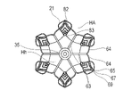
複数のエネルギー伝達要素配置部81は、拡張体21の周方向に略等間隔に配置される。それぞれのエネルギー伝達要素配置部81の凹部55の内側を形成する面に、エネルギー伝達要素22が配置される。
The plurality of energy transmission element arrangement portions 81 are arranged at approximately equal intervals in the circumferential direction of the extension body 21 . The energy transmission element 22 is arranged on the surface forming the inner side of the recess 55 of each energy transmission element arrangement portion 81 .
それぞれの対向部82は、拡張体21の拡張時にエネルギー伝達要素22のそれぞれと対向する。それぞれの対向部82は、底部連結部83のそれぞれの先端から拡張体21の周方向に略沿うように、先端方向へ向かって広がりつつ二股に分岐した複数の先端側起立ストラット84と、複数の背当て部85とを有する。第2先端側頂部70のそれぞれは、基端側に配置されて周方向に隣接する2つの底部連結部83のそれぞれから互いに近づくように延びる2つの先端側起立ストラット84が合流して形成される。複数の背当て部85は、底部連結部83のそれぞれから分岐する2つの先端側起立ストラット84を連結している。複数の背当て部85は、底部71に近い側から、先端側頂部57に近い側へ並んで配置される。それぞれの背当て部85は、2つの先端側起立ストラット84に連結される両端の間の部位が、先端側頂部57へ向かって突出するように湾曲している。それぞれの背当て部85は、先端側起立ストラット84に連結された両端を支点として、先端側頂部57に近い側が撓みやすい。このため、背当て部85は、基端側起立部73に配置されるエネルギー伝達要素22から受ける先端側へ向かう力によって撓むことができる。このため、エネルギー伝達要素22と背当て部85の間に挟まれる生体組織を、エネルギー伝達要素22に密着させることができる。それぞれの対向部82を形成する複数の背当て部85のうちの最も先端側頂部57に近い背当て部85は、先端側頂部57へ向かって突出している部位において、第1先端側頂部69に連結される。なお、それぞれの対向部82を形成する背当て部85の数は、特に限定されない。
Each facing portion 82 faces each of the energy transmission elements 22 when the expansion body 21 is expanded. Each facing portion 82 includes a plurality of tip-side upright struts 84 branched into two while spreading toward the tip direction so as to substantially follow the circumferential direction of the expansion body 21 from the tip of each bottom connecting portion 83 , and a plurality of struts 84 . and a backrest portion 85 . Each of the second distal apexes 70 is formed by joining two distal standing struts 84 extending toward each other from two bottom connecting portions 83 disposed proximally and circumferentially adjacent to each other. . A plurality of backrest portions 85 connect two distal standing struts 84 branching from each of the bottom connecting portions 83 . The plurality of backrest portions 85 are arranged side by side from the side closer to the bottom portion 71 toward the side closer to the tip side top portion 57 . Each backrest portion 85 is curved such that the portion between the ends connected to the two distal standing struts 84 protrudes toward the distal top portion 57 . Each of the back support portions 85 is easy to bend on the side closer to the tip-side apex 57 with both ends connected to the tip-side upright struts 84 as fulcrums. Therefore, the back support portion 85 can be bent by a force directed toward the distal side received from the energy transmission element 22 arranged on the proximal side upright portion 73 . Therefore, the living tissue sandwiched between the energy transmission element 22 and the back support portion 85 can be brought into close contact with the energy transmission element 22 . Of the plurality of backrest portions 85 forming each of the facing portions 82, the backrest portion 85 closest to the tip-side top portion 57 is located on the first tip-side top portion 69 at a portion protruding toward the tip-side top portion 57. concatenated. The number of backrest portions 85 forming each facing portion 82 is not particularly limited.
第2拡張部54は、基端連結部52から先端方向に向かって径方向外側に延びる基端側拡張部58と、基端側拡張部58の先端側に配置され径方向外向きの凸状に湾曲した基端側頂部59とを有している。
The second extended portion 54 includes a proximal side extended portion 58 extending radially outward toward the distal direction from the proximal connecting portion 52, and a radially outward convex shape disposed on the distal side of the proximal side extended portion 58. It has a curved proximal apex 59 .
基端側拡張部58は、複数の基端側ストラット構造90を有する。それぞれの基端側ストラット構造90は、複数のエネルギー伝達要素配置部81と、拡張体21の周方向において同一位相に配置される。複数の基端側ストラット構造90はそれぞれ、径方向の外側から見て拡張体21の軸心に略平行に、シャフト部31の先端部から基端側頂部59まで延びる複数の第3ストラット91と、周方向に隣接する第3ストラット91同士を連結する複数の副ストラット92とを有する。それぞれの副ストラット92は、周方向に隣接する2つの第3ストラット91の各々に接合部94で接合される2つの支持ストラット93を有している。2つの支持ストラット93は、2つの接合部94の間で角度を有するように連結されている。連結されている2つの支持ストラット93は、自然状態において、180度未満の連結角度γで連結されている。したがって、それぞれの副ストラット92は、2つの接合部94の間の直線距離よりも長く形成されている。このため、副ストラット92は、拡張体21が拡張する際に2つの接合部94の距離が長くなっても、副ストラット92を構成する2つの支持ストラット93の間の連結角度γを変更しつつ、2つの第3ストラット91を支持し続けることができる。このため、拡張体21は、牽引シャフト33により付与させる圧縮力により、第3ストラット91を略等間隔で広げつつ拡張することができる。
The proximal extension 58 has a plurality of proximal strut structures 90 . Each proximal strut structure 90 is arranged in phase with the plurality of energy transmission element arrangement portions 81 in the circumferential direction of the extension body 21 . Each of the plurality of proximal strut structures 90 includes a plurality of third struts 91 extending from the distal end of the shaft portion 31 to the proximal apex 59 substantially parallel to the axis of the expander 21 when viewed from the radially outer side. , and a plurality of secondary struts 92 connecting the third struts 91 adjacent in the circumferential direction. Each secondary strut 92 has two support struts 93 that are joined at joints 94 to each of two circumferentially adjacent third struts 91 . Two support struts 93 are connected at an angle between two joints 94 . Two connected support struts 93 are connected at a connection angle γ of less than 180 degrees in the natural state. Therefore, each secondary strut 92 is formed longer than the linear distance between the two joints 94 . Therefore, even if the distance between the two joints 94 increases when the extension body 21 expands, the secondary strut 92 changes the connection angle γ between the two support struts 93 that constitute the secondary strut 92. , can continue to support the two third struts 91 . Therefore, the expansion body 21 can be expanded by the compressive force applied by the traction shaft 33 while spreading the third struts 91 at substantially equal intervals.
基端側起立部73と先端側起立部72の間の間隔は、拡張部の拡張時において、径方向の内側よりも外側において軸方向に多少大きく開いていることが好ましい。これにより、基端側起立部73と先端側起立部72の間に、径方向の外側から生体組織を配置することが容易である。
It is preferable that the space between the proximal side upright portion 73 and the distal side upright portion 72 is slightly larger in the axial direction on the outer side than on the inner side in the radial direction when the expansion portion is expanded. This makes it easy to arrange the living tissue from the outside in the radial direction between the proximal side upright portion 73 and the distal side upright portion 72 .
エネルギー伝達要素22は、拡張部の拡張時において、基端側起立部73の先端側に向かう面に配置される。エネルギー伝達要素22は、基端側起立部73に設けられているので、凹部55が心房中隔HAを挟持する際、エネルギー伝達要素22からのエネルギーは、心房中隔HAに対して右心房側から伝達される。なお、エネルギー伝達要素22が先端側起立部72に設けられる場合、エネルギー伝達要素22からのエネルギーは、心房中隔HAに対して左心房側から伝達される。
The energy transmission element 22 is arranged on the surface of the proximal side upright portion 73 facing the distal side when the expansion portion is expanded. Since the energy transmission element 22 is provided on the proximal upright portion 73, when the recess 55 clamps the interatrial septum HA, the energy from the energy transmission element 22 is directed toward the right atrial side of the interatrial septum HA. transmitted from Note that when the energy transmission element 22 is provided on the distal upright portion 72, the energy from the energy transmission element 22 is transmitted to the interatrial septum HA from the left atrium side.
エネルギー伝達要素22は、例えば、外部装置であるエネルギー供給装置(図示しない)から電気エネルギーを受けるバイポーラ電極で構成される。この場合、各エネルギー伝達要素22配置部に配置されたエネルギー伝達要素22間で通電がなされる。エネルギー伝達要素22とエネルギー供給装置とは、絶縁性被覆材で被覆された導線(図示しない)により接続される。導線は、長尺部20及び操作部23を介して外部に導出され、エネルギー供給装置に接続される。
The energy transfer element 22 is composed of, for example, a bipolar electrode that receives electrical energy from an energy supply device (not shown), which is an external device. In this case, electricity is supplied between the energy transmission elements 22 arranged in each energy transmission element 22 arrangement portion. The energy transfer element 22 and the energy supply are connected by a wire (not shown) covered with an insulating coating. The conducting wire is led out through the elongated portion 20 and the operating portion 23 and connected to the energy supply device.
エネルギー伝達要素22は、他にも、モノポーラ電極として構成されていてもよい。この場合、体外に用意される対極板との間で通電がなされる。また、エネルギー伝達要素22は、エネルギー供給装置から高周波の電気エネルギーを受給して発熱する発熱素子(電極チップ)でもよい。この場合、各線材部に配置されたエネルギー伝達要素22間で通電がなされる。さらに、エネルギー伝達要素22は、マイクロ波エネルギー、超音波エネルギー、レーザー等のコヒーレント光、加熱した流体、冷却された流体、化学的な媒体により加熱や冷却作用を及ぼすもの、摩擦熱を生じさせるもの、電線等を備えるヒーター等のように、貫通孔Hhに対してエネルギーを付与可能な要素により構成することができ、具体的な形態は特に限定されない。
The energy transfer element 22 may alternatively be configured as a monopolar electrode. In this case, electricity is supplied between the electrode and the counter electrode prepared outside the body. Alternatively, the energy transfer element 22 may be a heating element (electrode tip) that generates heat by receiving high-frequency electrical energy from an energy supply device. In this case, electricity is supplied between the energy transmission elements 22 arranged on each wire portion. Further, the energy transfer element 22 can be heated or cooled by microwave energy, ultrasonic energy, coherent light such as a laser, heated fluid, cooled fluid, chemical media, or can generate frictional heat. , a heater having an electric wire, etc., which can apply energy to the through hole Hh, and the specific form thereof is not particularly limited.
本実施形態では、基端側起立部73にエネルギー伝達要素22を、先端側起立部72に背当て部85を、それぞれ設けているが、先端側起立部72にエネルギー伝達要素22を、基端側起立部73に背当て部85を、それぞれ設けてもよい。
In this embodiment, the energy transmission element 22 is provided on the proximal side upright portion 73, and the back support portion 85 is provided on the distal side upright portion 72, respectively. A backrest portion 85 may be provided on each of the side upright portions 73 .
拡張体21は、例えば、円筒から切り出して一体的に形成される。拡張体21を形成するストラットは、例えば、厚み50~500μm、幅0.3~2.0mmとすることができる。ただし、拡張体21を形成するストラットは、この範囲外の寸法を有していてもよい。また、ストラットの形状は、特に限定されず、例えば円形の断面形状や、それ以外の断面形状を有してもよい。
The expansion body 21 is, for example, cut out from a cylinder and formed integrally. The struts forming extension 21 can be, for example, 50-500 μm thick and 0.3-2.0 mm wide. However, the struts forming extension 21 may have dimensions outside this range. Also, the shape of the strut is not particularly limited, and may have, for example, a circular cross-sectional shape or other cross-sectional shape.
拡張体21は、金属材料で形成することができる。この金属材料としては、例えば、チタン系(Ti-Ni、Ti-Pd、Ti-Nb-Sn等)の合金、銅系の合金、ステンレス鋼、βチタン鋼、Co-Cr合金を用いることができる。なお、ニッケルチタン合金等のバネ性を有する合金等を用いるとよりよい。ただし、線材部の材料はこれらに限られず、その他の材料で形成してもよい。
The extension body 21 can be made of a metal material. As the metal material, for example, titanium-based (Ti--Ni, Ti--Pd, Ti--Nb--Sn, etc.) alloys, copper-based alloys, stainless steels, β-titanium steels, and Co--Cr alloys can be used. . In addition, it is better to use an alloy having spring properties such as a nickel-titanium alloy. However, the material of the wire portion is not limited to these, and may be formed of other materials.
長尺部20の外筒30およびシャフト部31は、ある程度の可撓性を有する材料により形成されるのが好ましい。そのような材料としては、例えば、ポリエチレン、ポリプロピレン、ポリブテン、エチレン-プロピレン共重合体、エチレン-酢酸ビニル共重合体、アイオノマー、あるいはこれら二種以上の混合物等のポリオレフィンや、軟質ポリ塩化ビニル樹脂、ポリアミド、ポリアミドエラストマー、ポリエステル、ポリエステルエラストマー、ポリウレタン、ポリテトラフルオロエチレン等のフッ素樹脂、ポリイミド、PEEK、シリコーンゴム、ラテックスゴム等が挙げられる。
The outer cylinder 30 and the shaft portion 31 of the elongated portion 20 are preferably made of a material having a certain degree of flexibility. Examples of such materials include polyolefins such as polyethylene, polypropylene, polybutene, ethylene-propylene copolymers, ethylene-vinyl acetate copolymers, ionomers, or mixtures of two or more thereof, soft polyvinyl chloride resins, Polyamide, polyamide elastomer, polyester, polyester elastomer, polyurethane, fluororesin such as polytetrafluoroethylene, polyimide, PEEK, silicone rubber, latex rubber and the like.
牽引シャフト33および牽引部35は、例えば、ニッケル-チタン合金、銅-亜鉛合金等の超弾性合金、ステンレス鋼等の金属材料、比較的剛性の高い樹脂材料などの長尺状の線材で形成することができる。また、上記にポリ塩化ビニル、ポリエチレン、ポリプロピレン、エチレンープロピレン共重合体、フッ素樹脂などの樹脂材料を被覆したもので形成してもよい。
The traction shaft 33 and the traction section 35 are made of a long wire such as a superelastic alloy such as a nickel-titanium alloy or a copper-zinc alloy, a metal material such as stainless steel, or a relatively rigid resin material. be able to. Alternatively, the above may be formed by coating with a resin material such as polyvinyl chloride, polyethylene, polypropylene, ethylene-propylene copolymer, or fluororesin.
次に、本実施形態に係る医療デバイス10を使用したシャント形成方法について、図10に示すフローチャートを参照しつつ説明する。説明する。本シャント形成方法は、心不全(左心不全)に罹患した患者に対して行われる。より具体的には、図5に示すように、心臓Hの左心室の心筋が肥大化してスティッフネス(硬さ)が増すことで、左心房HLaの血圧が高まる慢性心不全に罹患した患者に対して行われる処置の方法である。
Next, a shunt forming method using the medical device 10 according to this embodiment will be described with reference to the flowchart shown in FIG. explain. This method of forming a shunt is performed on a patient suffering from heart failure (left heart failure). More specifically, as shown in FIG. 5, the myocardium in the left ventricle of the heart H is hypertrophied and stiffness (hardness) is increased, resulting in increased blood pressure in the left atrium HLa for a patient suffering from chronic heart failure. It is the method of treatment that is performed.
本実施形態のシャント形成方法は、心房中隔HAに貫通孔Hhを形成するステップ(S1)と、貫通孔Hhに拡張体21を配置するステップ(S2)と、受容空間74に生体組織を受容するステップ(S3)と、拡張体21によって貫通孔Hhの径を拡張させるステップ(S4)と、貫通孔Hh付近における血行動態を確認するステップ(S5)と、貫通孔Hhの大きさを維持するための維持処置を行うステップ(S6)と、維持処置が施された後の貫通孔Hh付近における血行動態を確認するステップ(S7)と、を有している。
The method of forming a shunt according to the present embodiment includes the steps of forming a through hole Hh in the interatrial septum HA (S1), arranging the expansion body 21 in the through hole Hh (S2), and receiving a living tissue in the receiving space 74. (S3), expanding the diameter of the through-hole Hh by the expander 21 (S4), confirming hemodynamics in the vicinity of the through-hole Hh (S5), and maintaining the size of the through-hole Hh and a step (S7) of confirming hemodynamics in the vicinity of the through hole Hh after the maintenance treatment.
術者は、貫通孔Hhの形成に際し、ガイディングシース及びダイレータが組み合わされたイントロデューサを心房中隔HA付近まで送達する。イントロデューサは、例えば、下大静脈Ivを介して右心房HRaに送達することができる。また、イントロデューサの送達は、ガイドワイヤ11を使用して行うことができる。術者は、ダイレータにガイドワイヤ11を挿通し、ガイドワイヤ11に沿わせて、イントロデューサを送達させることができる。なお、生体に対するイントロデューサの挿入、ガイドワイヤ11の挿入等は、血管導入用のイントロデューサを用いるなど、公知の方法で行うことができる。
When forming the through hole Hh, the operator delivers an introducer in which a guiding sheath and a dilator are combined to the vicinity of the interatrial septum HA. The introducer can be delivered to the right atrium HRa, for example, via the inferior vena cava Iv. Also, delivery of the introducer can be done using a guidewire 11 . The operator can pass the guidewire 11 through the dilator and deliver the introducer along the guidewire 11 . Note that the insertion of the introducer into the living body, the insertion of the guide wire 11, and the like can be performed by a known method such as using an introducer for blood vessel introduction.
S1のステップにおいて、術者は、右心房HRa側から左心房HLa側に向かって、穿刺デバイス(図示しない)を貫通させ、貫通孔Hhを心房中隔HAの卵円窩に形成する。穿刺デバイスとしては、例えば、先端が尖ったワイヤ等のデバイスを使用することができる。穿刺デバイスは、ダイレータに挿通させて心房中隔HAまで送達する。穿刺デバイスは、ダイレータからガイドワイヤ11を抜去した後、ガイドワイヤ11に代えて心房中隔HAまで送達することができる。
In step S1, the operator penetrates a puncture device (not shown) from the right atrium HRa side toward the left atrium HLa side to form a through hole Hh in the fossa ovalis of the interatrial septum HA. As a puncture device, for example, a device such as a wire with a sharp tip can be used. A puncture device is passed through the dilator and delivered to the atrial septum HA. After removing the guidewire 11 from the dilator, the puncture device can be delivered to the interatrial septum HA instead of the guidewire 11 .
次に、術者は、予め挿入されたガイドワイヤ11に沿って、バルーンカテーテル150を心房中隔HA付近に送達する。図6に示すように、バルーンカテーテル150は、シャフト部151の先端部にバルーン152を有している。バルーン152を心房中隔HAに配置したら、径方向に拡張させ、貫通孔Hhを押し広げる。
Next, the operator delivers the balloon catheter 150 to the vicinity of the interatrial septum HA along the pre-inserted guidewire 11 . As shown in FIG. 6, the balloon catheter 150 has a balloon 152 at the tip of a shaft portion 151 . Once the balloon 152 is positioned in the interatrial septum HA, it is radially expanded to expand the through hole Hh.
S2のステップにおいては、図7に示すように、予め挿入されたガイドワイヤ11に沿って、医療デバイス10を心房中隔HA付近に送達する。このとき、医療デバイス10の先端部は、心房中隔HAを貫通して、左心房HLaに達するようにする。また、医療デバイス10の挿入の際、拡張体21は、外筒30に収納された状態となっている。
In step S2, as shown in FIG. 7, the medical device 10 is delivered near the interatrial septum HA along the pre-inserted guidewire 11 . At this time, the distal end of the medical device 10 penetrates the interatrial septum HA and reaches the left atrium HLa. Further, when inserting the medical device 10 , the expansion body 21 is in a state of being housed in the outer cylinder 30 .
次に、S3のステップにおいて、外筒30を基端側に移動させることにより、拡張体21を露出させる。これにより、図8に示すように、拡張体21は拡径し、凹部55は心房中隔HAの貫通孔Hhに配置されて、受容空間74に貫通孔Hhを取り囲む生体組織を受容する。貫通孔Hhは、拡張体21によって拡張された状態を維持される。
Next, in step S3, the expansion body 21 is exposed by moving the outer cylinder 30 to the proximal end side. As a result, as shown in FIG. 8, the expansion body 21 is expanded in diameter, and the recess 55 is arranged in the through hole Hh of the interatrial septum HA to receive the living tissue surrounding the through hole Hh in the receiving space 74 . The through hole Hh is kept expanded by the expansion body 21 .
S4のステップにおいて、術者は、心房中隔HAが凹部55の受容空間74に受容された状態で操作部23を操作し、牽引シャフト33を基端側に移動させ、図9に示すように拡張体21の凹部55で生体組織を挟む。ところで、心房中隔HA(生体組織)の厚みは個体差があり、厚い場合もあれば薄い場合もある。心房中隔HAが厚い場合、牽引シャフト33の牽引によって拡張体21に圧縮力が作用する際に、第2セクション62は、第2ストラット64の第1分岐角度αおよび第2分岐角度βが増加するように湾曲できる。すなわち、緩衝部である第2セクション62は、受力部51から先端側頂部57に向かう方向とは異なる方向へ変形する。これにより、拡張体21は、牽引シャフト33から受ける圧縮力が緩和されるため、拡張体21が径方向外側へ拡張しすぎることを抑制できる。また、先端側頂部57と第1合流部65との間にある補助湾曲部67は、多様な方向へ変形可能である。このため、補助湾曲部67も、牽引シャフト33の牽引によって拡張体21に圧縮力が作用する際に、受力部51から先端側頂部57に向かう方向とは異なる方向へ変形する緩衝部として機能し、圧縮力をさらに緩和させることができる。また、基端側ストラット構造90の副ストラット92も、牽引シャフト33の牽引によって拡張体21に圧縮力が作用する際に、基端連結部52から基端側頂部59に向かう方向とは異なる方向へ変形する。すなわち、それぞれの副ストラット92を構成する2つの支持ストラット93が、連結角度γを増加させつつ変形して、緩衝部として機能できる。したがって、それぞれの緩衝部の変形により、生体組織が厚い場合と薄い場合での拡張体21の径方向外側への拡張量の変動が抑制される。このため、心房中隔HAの厚みが厚い場合や薄い場合であっても、貫通孔Hhを、大きすぎも小さすぎもせずに、適切な大きさとすることができる。
In step S4, the operator operates the operation part 23 with the interatrial septum HA received in the receiving space 74 of the recess 55 to move the traction shaft 33 to the proximal end side, as shown in FIG. The living tissue is sandwiched between the concave portions 55 of the expansion member 21 . By the way, the thickness of the interatrial septum HA (biological tissue) varies from individual to individual, and may be thick or thin. When the atrial septum HA is thick, the second section 62 increases the first branch angle α and the second branch angle β of the second struts 64 when compressive force is exerted on the expander 21 by pulling the pull shaft 33 . It can be curved to In other words, the second section 62 that is the cushioning portion deforms in a direction different from the direction from the force receiving portion 51 toward the distal top portion 57 . As a result, the expansion body 21 is relieved of the compressive force received from the traction shaft 33, so that the expansion body 21 can be prevented from expanding excessively outward in the radial direction. In addition, the auxiliary curved portion 67 between the distal top portion 57 and the first confluence portion 65 can be deformed in various directions. Therefore, the auxiliary bending portion 67 also functions as a cushioning portion that deforms in a direction different from the direction from the force receiving portion 51 toward the distal top portion 57 when a compressive force acts on the expandable body 21 due to the traction of the pulling shaft 33. and the compressive force can be further relieved. The secondary struts 92 of the proximal strut structure 90 are also configured in a direction different from the direction from the proximal connecting portion 52 to the proximal apex 59 when compressive force is applied to the expander 21 by traction of the traction shaft 33 . Transform into. That is, the two support struts 93 forming each secondary strut 92 can function as buffers by deforming while increasing the connection angle γ. Therefore, the deformation of each cushioning portion suppresses variation in the radially outward expansion amount of the expandable body 21 depending on whether the living tissue is thick or thin. Therefore, even when the interatrial septum HA is thick or thin, the through hole Hh can be of an appropriate size, neither too large nor too small.
貫通孔Hhに拡張体21を配置したら、S5のステップにおいて血行動態の確認を行う。術者は、図5に示すように、下大静脈Iv経由で右心房HRaに対し、血行動態確認用デバイス100を送達する。血行動態確認用デバイス100としては、例えば、公知のエコーカテーテルを使用することができる。術者は、血行動態確認用デバイス100で取得されたエコー画像を、ディスプレイ等の表示装置に表示させ、その表示結果に基づいて貫通孔Hhを通る血液量を確認することができる。
After placing the expansion body 21 in the through hole Hh, hemodynamics is confirmed in step S5. The operator delivers the hemodynamic confirmation device 100 to the right atrium HRa via the inferior vena cava Iv, as shown in FIG. As the hemodynamic confirmation device 100, for example, a known echo catheter can be used. The operator can display the echo image acquired by the hemodynamic confirmation device 100 on a display device such as a display, and confirm the amount of blood passing through the through-hole Hh based on the display result.
次に、S6のステップにおいて、術者は、貫通孔Hhの大きさを維持するために維持処置を行う。維持処置では、エネルギー伝達要素22を通じて貫通孔Hhの縁部に高周波エネルギーを付与することにより、貫通孔Hhの縁部を高周波エネルギーによって焼灼(加熱焼灼)する。
Next, in step S6, the operator performs maintenance treatment to maintain the size of the through-hole Hh. In the maintenance treatment, high-frequency energy is applied to the edge of the through-hole Hh through the energy transmission element 22 to cauterize (heat cauterize) the edge of the through-hole Hh with high-frequency energy.
エネルギー伝達要素22を通して貫通孔Hhの縁部付近の生体組織が焼灼されると、縁部付近には生体組織が変性した変性部が形成される。変性部における生体組織は弾性を失った状態となるため、貫通孔Hhは拡張体21により押し広げられた際の形状を維持できる。貫通孔Hhは、緩衝部を備える拡張体21により適切な大きさで保持されて焼灼させるため、適切な大きさで形状を維持される。
When the living tissue near the edge of the through hole Hh is cauterized through the energy transmission element 22, a denatured portion of the living tissue is formed near the edge. Since the living tissue in the denatured portion loses its elasticity, the through-hole Hh can maintain the shape when expanded by the expander 21 . The through-hole Hh is held in an appropriate size by the expanding body 21 having a buffer portion for cauterization, so that the through-hole Hh is maintained in an appropriate size and shape.
維持処置後には、S7のステップにおいて再度血行動態を確認し、貫通孔Hhを通る血液量が所望の量となっている場合、術者は、拡張体21を縮径させ、外筒30に収納した上で、貫通孔Hhから抜去する。さらに、医療デバイス10全体を生体外に抜去し、処置を終了する。
After the maintenance treatment, the hemodynamics are confirmed again in step S7, and if the amount of blood passing through the through hole Hh is the desired amount, the operator reduces the diameter of the expandable body 21 and stores it in the outer cylinder 30. After that, it is removed from the through hole Hh. Furthermore, the entire medical device 10 is removed from the body, and the treatment is completed.
以上のように、本実施形態に係る医療デバイス10は、受力部51を含む先端部を有する径方向に拡縮可能な拡張体21と、拡張体21の基端が固定された先端部を有する長尺なシャフト部31と、拡張体21に沿って設けられる複数のエネルギー伝達要素22(電極部)と、シャフト部31の内部に配置されるとともに、シャフト部31の先端部から突出して拡張体21の受力部51に接続可能であり、シャフト部31に対して摺動可能な牽引シャフト33と、を備え、拡張体21は、受力部51から基端方向に向かって径方向外側に延びる先端側拡張部56と、先端側拡張部56の基端側に配置され径方向外向きの凸状に湾曲した先端側頂部57と、を含む第1拡張部53と、シャフト部31の先端部から先端方向に向かって径方向外側に延びる基端側拡張部58と、基端側拡張部58の先端側に配置され径方向外向きの凸状に湾曲した基端側頂部59と、を含む第2拡張部54と、径方向内側に窪み、かつ、基端側頂部59と先端側頂部57とを連結するように延び、拡張体21の拡張時に生体組織を受容可能な受容空間74を画成する凹部55と、を有し、凹部55は、径方向の最も内側に位置する底部71と、底部71の先端から先端側頂部57まで径方向外側に延びる先端側起立部72と、底部71の基端から基端側頂部59まで径方向外側に延びる基端側起立部73と、有し、先端側起立部72と基端側起立部73のいずれかは、拡張体21の周方向に略等間隔に、複数のエネルギー伝達要素のそれぞれが配置される複数のエネルギー伝達要素配置部81を有し、先端側起立部72と基端側起立部73の他方は、拡張体21の拡張時に複数のエネルギー伝達要素のそれぞれと対向する複数の対向部82を有し、牽引シャフト33は、シャフト部31に対して基端方向に摺動することにより、複数のエネルギー伝達要素配置部81と複数の対向部82とが近づくようにシャフト部31の軸心に沿って圧縮する圧縮力を、受力部51を介して拡張体21に及ぼすように構成されており、拡張体21は、第1拡張部53に配置され、先端側拡張部56に沿って受力部51から先端側頂部57に向かう方向とは異なる方向に変形することで圧縮力を緩和するように構成された緩衝部、または、第2拡張部54に配置され、基端側拡張部58に沿って拡張体21の基端から基端側頂部59に向かう方向とは異なる方向に変形することで圧縮力を緩和するように構成された緩衝部を有する。
As described above, the medical device 10 according to the present embodiment includes the radially expandable expandable body 21 having the distal end portion including the force receiving portion 51, and the distal end portion to which the proximal end of the expandable body 21 is fixed. A long shaft portion 31, a plurality of energy transmission elements 22 (electrode portions) provided along the extension body 21, and an extension body disposed inside the shaft portion 31 and protruding from the distal end portion of the shaft portion 31. a traction shaft 33 connectable to the force receiving portion 51 of 21 and slidable relative to the shaft portion 31, the extension body 21 extending radially outward from the force receiving portion 51 in the proximal direction; a first extension 53 including an extending distal extension 56 and a distal apex 57 arranged on the proximal side of the distal extension 56 and convexly curved radially outward; A proximal extension portion 58 extending radially outward toward the distal direction from the portion, and a proximal top portion 59 arranged on the distal side of the proximal extension portion 58 and curved radially outward in a convex shape. and a receiving space 74 that is recessed radially inward and extends to connect the proximal side top portion 59 and the distal side top portion 57 to receive a living tissue when the expandable body 21 is expanded. The recess 55 defines a radially innermost bottom portion 71 , a distal side upright portion 72 extending radially outwardly from the distal end of the bottom portion 71 to a distal top portion 57 , and a bottom portion. and a proximal upright portion 73 extending radially outward from the proximal end of 71 to the proximal apex portion 59 , wherein either the distal upright portion 72 or the proximal upright portion 73 extends in the circumferential direction of the expander 21 . has a plurality of energy transmission element arrangement portions 81 in which a plurality of energy transmission elements are respectively arranged at substantially equal intervals, and the other of the distal end side erect portion 72 and the proximal end side erect portion 73 is the extension of the extension body 21 The traction shaft 33 sometimes has a plurality of opposing portions 82 that face each of the plurality of energy transmission elements, and the traction shaft 33 slides in the proximal direction with respect to the shaft portion 31 , so that the plurality of energy transmission element arrangement portions 81 and 81 are arranged. It is configured to apply a compressive force along the axis of the shaft portion 31 so that the plurality of facing portions 82 are brought closer to each other on the expandable body 21 via the force receiving portion 51 . A cushioning portion arranged in the 1 expansion portion 53 and configured to alleviate the compressive force by deforming in a direction different from the direction from the force receiving portion 51 toward the tip side top portion 57 along the tip side expansion portion 56, Alternatively, a direction different from the direction located in the second extension 54 and extending from the proximal end of the extension 21 to the proximal top 59 along the proximal extension 58 . It has a cushioning portion configured to relieve the compressive force by deforming into a shape.
上記のように構成した医療デバイス10は、牽引シャフト33の牽引によって拡張体21に圧縮力が作用する際に、受力部51から先端側頂部57に向かう方向とは異なる方向、または拡張体21の基端から基端側頂部59に向かう方向とは異なる方向に緩衝部が変形することで圧縮力が緩和されるため、拡張体21が径方向外側へ拡張しすぎることを抑制できる。したがって、拡張体21の受容空間74に受容する生体組織が厚い場合と薄い場合での拡張体21の径方向外側への拡張量の変動を抑制できる。このため、医療デバイス10は、生体組織を貫通する孔に通されて、圧縮力により径方向外側へ拡張する拡張体21の径方向への拡張量が、生体組織の厚みのバラツキによって変動することを抑制できる。このため、本医療デバイス10は、生体組織の厚みのバラツキから影響を受けにくくなり、生体組織の孔を拡張しすぎることを抑制して、安全性の高い適切な焼灼を可能とする。
In the medical device 10 configured as described above, when a compressive force acts on the expansion body 21 due to the traction of the pulling shaft 33, the direction different from the direction from the force receiving portion 51 to the distal top portion 57 or the expansion body 21 Since the compressive force is relieved by deformation of the cushioning portion in a direction different from the direction from the proximal end toward the proximal side top portion 59, it is possible to prevent the expandable body 21 from expanding excessively outward in the radial direction. Therefore, it is possible to suppress variation in the radially outward expansion amount of the expandable body 21 depending on whether the living tissue received in the receiving space 74 of the expandable body 21 is thick or thin. For this reason, the medical device 10 is passed through a hole penetrating the living tissue, and expands radially outward due to the compressive force. can be suppressed. Therefore, the medical device 10 is less likely to be affected by variations in the thickness of the living tissue, suppresses excessive expansion of the pore of the living tissue, and enables appropriate cauterization with high safety.
また、第1拡張部53は、受力部51から基端方向に向かって径方向外側に延び、先端側拡張部56を形成する複数の先端側ストラット構造60を有し、複数の先端側ストラット構造60はそれぞれ、各先端側ストラット構造60に沿って受力部51から先端側頂部57に向かう方向とは異なる方向に湾曲可能な湾曲部(第2ストラット64)を緩衝部として有する。これにより、緩衝部を単純な構造で実現できる。
The first extension portion 53 also has a plurality of distal strut structures 60 extending radially outward from the force receiving portion 51 toward the proximal direction to form a distal extension portion 56, and a plurality of distal struts. Each structure 60 has a bendable portion (second strut 64 ) as a buffer that can bend in a direction different from the direction along each distal strut structure 60 from the force receiving portion 51 toward the distal apex 57 . As a result, the buffer section can be realized with a simple structure.
また、複数の先端側ストラット構造60はそれぞれ、径方向の外側から見て拡張体21の軸心に略平行に受力部51から延びる第1ストラット63を含む第1セクション61と、第1セクション61の基端から拡張体21の周方向に略沿うように二股に分岐した2つの第2ストラット64を含み、先端側頂部57に連結した第2セクション62と、を有し、第2セクション62は、分岐している2つの第2ストラット64のなす第1分岐角度αおよび第2分岐角度βが増すように湾曲することで圧縮力を緩和する緩衝部として機能する。これにより、先端側ストラット構造60の第2セクション62は、分岐している2つの第2ストラット64のなす第1分岐角度αおよび第2分岐角度βが増すように湾曲することで、圧縮力を緩和させて、拡張体21が径方向外側へ拡張しすぎることを抑制できる。
In addition, each of the plurality of distal strut structures 60 includes a first section 61 including a first strut 63 extending from the force receiving portion 51 substantially parallel to the axis of the extension body 21 when viewed from the radially outer side, and a first section a second section 62 including two second struts 64 bifurcated from the proximal end of 61 so as to generally follow the circumferential direction of the expander 21 and connected to the distal top portion 57; functions as a cushioning portion that relieves the compressive force by bending such that the first branch angle α and the second branch angle β formed by the two branched second struts 64 increase. Thereby, the second section 62 of the distal strut structure 60 bends to increase the first branch angle α and the second branch angle β formed by the two branched second struts 64, thereby reducing the compressive force. It is possible to suppress the expansion body 21 from expanding excessively outward in the radial direction.
また、第2セクション62は、先端側頂部57近傍において、2つの第2ストラット64のそれぞれが周方向に隣接する他の第2セクション62の2つの第2ストラット64の一方と合流する複数の第1合流部65および第2合流部66を有する。これにより、拡張体21は、隣接する先端側ストラット構造60同士が周方向に互いに支え合う形態となるため、拡張時に捩じれ難くなる。このため、拡張体21によって生体組織の適切な位置を適切に拡張させて、適切な焼灼が可能となる。
In addition, the second section 62 has a plurality of second struts 64 where each of the two second struts 64 merges with one of the two second struts 64 of the other second section 62 adjacent in the circumferential direction in the vicinity of the distal top portion 57 . It has a first junction 65 and a second junction 66 . As a result, the expansion body 21 is configured such that the adjacent distal strut structures 60 support each other in the circumferential direction, so that the expansion body 21 is less likely to be twisted during expansion. Therefore, the expandable body 21 can appropriately expand the appropriate position of the living tissue to perform appropriate cauterization.
また、第2セクション62は、エネルギー伝達要素配置部81または対向部82と拡張体21の周方向において同一位相に配置された先端側頂部57と、複数の第1合流部65との間に、緩衝部として機能する補助湾曲部67を有する。これにより、補助湾曲部67が変形することで、圧縮力をさらに緩和させることができるため、圧縮力が拡張力へ、より変換され難くなる。
In addition, the second section 62 is provided between the energy transmission element arrangement portion 81 or the facing portion 82 and the distal end side apex portion 57 arranged in the same phase in the circumferential direction of the extension body 21 and the plurality of first confluence portions 65, It has an auxiliary curved portion 67 that functions as a buffer. As a result, the compressive force can be further reduced by deforming the auxiliary bending portion 67, so that the compressive force is less likely to be converted into the expansive force.
また、複数の先端側ストラット構造60は、複数のエネルギー伝達要素22(電極部)の2倍の数の第1セクション61および合流部(第1合流部65および第2合流部66)を有し、合流部は、拡張体21の周方向において、複数のエネルギー伝達要素配置部81および複数の対向部82と同一位相に配置された第1合流部65と、複数のエネルギー伝達要素配置部81および複数の対向部82とは異なる位相に配置された第2合流部66とを、交互に有する。これにより、拡張体21は、隣接する先端側ストラット構造60同士が周方向に互いに支え合う形態となるため、拡張時に捩じれ難くなる。このため、拡張体21によって生体組織の適切な位置を適切に拡張させて、適切な焼灼が可能となる。
Also, the plurality of distal strut structures 60 has twice as many first sections 61 and junctions (first junctions 65 and second junctions 66) as the plurality of energy transfer elements 22 (electrode portions). , the merging portion includes a first merging portion 65 arranged in the same phase as the plurality of energy transmission element arrangement portions 81 and the plurality of facing portions 82 in the circumferential direction of the extension body 21, the plurality of energy transmission element arrangement portions 81 and It has a plurality of opposing portions 82 and second merging portions 66 arranged in different phases alternately. As a result, the expansion body 21 is configured such that the adjacent distal strut structures 60 support each other in the circumferential direction, so that the expansion body 21 is less likely to be twisted during expansion. Therefore, the expandable body 21 can appropriately expand the appropriate position of the living tissue to perform appropriate cauterization.
また、医療デバイス10は、第1合流部65と先端側頂部57との間に、緩衝部として機能する補助湾曲部67を有する。これにより、補助湾曲部67が変形することで、圧縮力をさらに緩和させることができるため、圧縮力が拡張力へ、より変換され難くなる。
In addition, the medical device 10 has an auxiliary curved portion 67 functioning as a cushioning portion between the first confluence portion 65 and the distal top portion 57 . As a result, the compressive force can be further reduced by deforming the auxiliary bending portion 67, so that the compressive force is less likely to be converted into the expansive force.
また、凹部55は、先端側ストラット構造60に対して先端側頂部57を介して連結し、先端側起立部72、基端側起立部73及び底部71を画成する凹型ストラット構造80を有し、凹型ストラット構造80は、底部71に、複数のエネルギー伝達要素配置部81と複数の対向部82のそれぞれの対を連結する複数の底部連結部83を有し、複数の底部連結部83は、拡張体21の周方向において、第1ストラット63とは異なる位相に配置される。これにより、異なる位相に配置される底部連結部83と第1ストラット63との間に、周方向へ延びる部位が存在することになるため、分岐角度を広げる方向に力が作用しやすくなり、圧縮力が拡張力に変換され難くなる。
The recess 55 also has a recessed strut structure 80 that connects to the distal strut structure 60 via the distal top 57 and defines a distal upright 72 , a proximal upright 73 and a bottom 71 . , the recessed strut structure 80 has a plurality of bottom connecting portions 83 connecting respective pairs of a plurality of energy transfer element placement portions 81 and a plurality of opposing portions 82 at the bottom portion 71, the plurality of bottom connecting portions 83 being: In the circumferential direction of the extension body 21 , it is arranged in a phase different from that of the first struts 63 . As a result, since there is a portion extending in the circumferential direction between the bottom connecting portion 83 and the first strut 63 that are arranged in different phases, a force tends to act in the direction of widening the branching angle, resulting in compression. It becomes difficult for force to be converted into expansion force.
また、エネルギー伝達要素配置部81は、基端側起立部73に設けられており、緩衝部は、先端側拡張部56にのみ設けられる。これにより、拡張体21の圧縮時に、第2拡張部54が圧縮力を効果的に伝達して、エネルギー伝達要素を組織に確実に押し当てることができる。
Also, the energy transmission element arrangement portion 81 is provided on the proximal side upright portion 73 , and the buffer portion is provided only on the distal side expanded portion 56 . This allows the second extension 54 to effectively transmit the compressive force when the extension body 21 is compressed, ensuring that the energy transmission element is pressed against the tissue.
また、第2拡張部54は、シャフト部31の先端部から先端方向に向かって径方向外側に延び、基端側拡張部58を形成する複数の基端側ストラット構造90を有し、複数の基端側ストラット構造90はそれぞれ、複数のエネルギー伝達要素配置部81と拡張体21の周方向において同一位相に配置され、径方向の外側から見て拡張体21の軸心に略平行にシャフト部31の先端部から基端側頂部59まで延びる第3ストラット91を有する。これにより、拡張体21の圧縮時に、第2拡張部54が圧縮力を効果的に伝達して、エネルギー伝達要素を組織に確実に押し当てることができる。
The second extension portion 54 also includes a plurality of proximal strut structures 90 extending radially outward from the distal end of the shaft portion 31 in a distal direction to form the proximal extension portion 58, and a plurality of Each of the proximal strut structures 90 is arranged in the same phase in the circumferential direction of the plurality of energy transmission element arrangement portions 81 and the expansion body 21, and the shaft portion is substantially parallel to the axis of the expansion body 21 when viewed from the radially outer side. It has a third strut 91 extending from the distal end of 31 to the proximal apex 59 . This allows the second extension 54 to effectively transmit the compressive force when the extension body 21 is compressed, ensuring that the energy transmission element is pressed against the tissue.
また、第2拡張部54は、複数の第2ストラット64構造のうち周方向に隣接する第3ストラット91同士を連結する複数の副ストラット92を有し、複数の副ストラット92はそれぞれ、複数の第3ストラット91のうち周方向に隣接する2つの第3ストラット91の各々に接合される2つの接合部94を有する少なくとも1つの支持ストラット93を有し、複数の支持ストラット93はそれぞれ、2つの接合部94の間の直線距離よりも長く形成される。これにより、圧縮力を受けた第2ストラット64構造が、エネルギー伝達要素を組織へ押し当てる際に周方向へ捩れることを、支持ストラット93により抑制できる。このため、医療デバイス10は、エネルギー伝達要素を組織へ押し当てる力が分散しにくくなり、エネルギー伝達要素を生体組織へ効果的に押し当てることができる。
In addition, the second extension portion 54 has a plurality of secondary struts 92 that connect the circumferentially adjacent third struts 91 among the plurality of second struts 64 structures. Each of the plurality of support struts 93 has at least one support strut 93 having two joints 94 joined to each of two circumferentially adjacent third struts 91, and each of the plurality of support struts 93 has two It is formed longer than the linear distance between the joints 94 . This allows the support struts 93 to restrain the second strut 64 structure, which is subjected to compressive force, from twisting in the circumferential direction when the energy transmission element is pressed against the tissue. Therefore, in the medical device 10, the force of pressing the energy transmission element against the tissue is less likely to disperse, and the energy transmission element can be effectively pressed against the living tissue.
また、本発明は、シャント形成方法をも提供する。シャント形成方法は、上述した医療デバイス1010を下大静脈Ivから右心房HRa内に挿入し、卵円窩に形成した孔に収縮した拡張体21を挿入し、孔内で拡張体21を拡張させて、凹部55により画成される受容空間74に、孔を取り囲む生体組織を配置し、牽引シャフト33をシャフト部31に対して基端方向に摺動することにより、凹部55の先端側起立部72と基端側起立部73とが互いに近づくように拡張体21が圧縮され、先端側拡張部56に沿って受力部51から先端側頂部57に向かう方向とは異なる方向に緩衝部を変形させることで圧縮力を緩和させ、または、第2拡張部54に配置され、基端側拡張部58に沿って拡張体21の基端から基端側頂部59に向かう方向とは異なる方向に緩衝部を変形させることで圧縮力を緩和させつつ、凹部55の先端側起立部72または基端側起立部73に沿って凹部55に面するように配置されたエネルギー伝達要素を生体組織に密着させ、孔の自然治癒による閉塞を阻害するように、生体組織に密着したエネルギー伝達要素を用いて受容空間74に配置された生体組織を焼灼する、シャント形成方法である。
The present invention also provides a shunt forming method. The method of forming a shunt involves inserting the above-described medical device 1010 into the right atrium HRa from the inferior vena cava Iv, inserting the contracted expansion body 21 into the hole formed in the fossa ovalis, and expanding the expansion body 21 in the hole. Then, the living tissue surrounding the hole is placed in the receiving space 74 defined by the recess 55 , and the traction shaft 33 is slid proximally relative to the shaft portion 31 . The expandable body 21 is compressed so that the 72 and the proximal upright portion 73 are brought closer to each other, and the cushioning portion is deformed in a direction different from the direction from the force receiving portion 51 to the distal top portion 57 along the distal expandable portion 56 . , or located in the second extension 54 to cushion in a direction different from the direction from the proximal end of the extension 21 to the proximal apex 59 along the proximal extension 58 . The energy transmission element arranged to face the recessed portion 55 along the distal side upright portion 72 or the proximal side upright portion 73 of the recessed portion 55 is brought into close contact with the living tissue while reducing the compressive force by deforming the portion. is a method of forming a shunt that ablates tissue located in a receiving space 74 using an energy delivery element in intimate contact with the tissue so as to inhibit the natural healing closure of the hole.
上記のように構成したシャント形成方法は、牽引シャフト33の牽引によって拡張体21に圧縮力が作用する際に、受力部51から先端側頂部57に向かう方向とは異なる方向、または拡張体21の基端から基端側頂部59に向かう方向とは異なる方向に緩衝部が変形することで圧縮力が緩和されるため、拡張体21が径方向外側へ拡張しすぎることを抑制できる。したがって、生体組織が厚い場合と薄い場合での拡張体21の径方向外側への拡張量の変動を抑制できる。このため、シャント形成方法は、生体組織を貫通する孔に通されて、圧縮力により径方向外側へ拡張する拡張体21の径方向への拡張量が、生体組織の厚みのバラツキによって変動することを抑制できる。このため、本シャント形成方法は、生体組織の厚みのバラツキから影響を受けにくくなり、生体組織の孔を拡張しすぎることを抑制して、安全性の高い適切な焼灼を可能とする。
In the shunt forming method configured as described above, when a compressive force acts on the expansion body 21 due to the traction of the pulling shaft 33, the direction different from the direction from the force receiving portion 51 to the tip side top portion 57 or the expansion body 21 Since the compressive force is relieved by deformation of the cushioning portion in a direction different from the direction from the proximal end toward the proximal side top portion 59, it is possible to prevent the expandable body 21 from expanding excessively outward in the radial direction. Therefore, it is possible to suppress variation in the radially outward expansion amount of the expansion body 21 depending on whether the living tissue is thick or thin. Therefore, in the shunt forming method, the amount of expansion in the radial direction of the expansion body 21, which is passed through a hole penetrating the living tissue and expands radially outward due to the compressive force, fluctuates depending on the thickness of the living tissue. can be suppressed. Therefore, the present shunt forming method is less likely to be affected by variations in the thickness of the living tissue, suppresses excessive expansion of the pore of the living tissue, and enables appropriate cauterization with high safety.
なお、本発明は、上述した実施形態のみに限定されるものではなく、本発明の技術的思想内において当業者により種々変更が可能である。したがって、緩衝部が配置される位置は、第1拡張部または第2拡張部であれば、特に限定されない。例えば、図11および12に示す第1変形例のように、前述の図1~4に示す実施形態と比較して、第1ストラット63の数が半分の6本であり、第2ストラット64の数が半分の12本であってもよい。第1ストラット63は、第3ストラット91、エネルギー伝達要素配置部81、対向部82およびエネルギー伝達要素22とは異なる位相に配置される。そして、第2ストラット64が集合する合流部は、全て第1合流部65であり、図3に示される第2合流部66、連結ストラット68および第2先端側頂部70は設けられなくてもよい。第1合流部65と第1先端側頂部69の間には、補助湾曲部67が設けられるが、補助湾曲部67が設けられなくてもよい。
It should be noted that the present invention is not limited to the above-described embodiments, and various modifications can be made by those skilled in the art within the technical concept of the present invention. Therefore, the position where the buffer is arranged is not particularly limited as long as it is the first extension or the second extension. For example, as in a first modification shown in FIGS. 11 and 12, the number of first struts 63 is half, which is six, compared to the embodiment shown in FIGS. The number may be half, twelve. The first strut 63 is arranged in a different phase than the third strut 91 , the energy transfer element arrangement portion 81 , the facing portion 82 and the energy transfer element 22 . The merging portion where the second struts 64 gather is the first merging portion 65, and the second merging portion 66, the connecting strut 68 and the second tip side top portion 70 shown in FIG. 3 may not be provided. . An auxiliary curved portion 67 is provided between the first confluence portion 65 and the first tip-side top portion 69, but the auxiliary curved portion 67 may not be provided.
また、図13および14に示す第2変形例のように、図1~4に示す実施形態と比較して、第1ストラット63の数が4分の1の3本であり、第2ストラット64(緩衝部)の数が4分の1の6本であってもよい。そして、3本の第1ストラット63から分岐した6本の第2ストラット64のそれぞれは、集合せずに、6個の補助湾曲部67(緩衝部)のそれぞれに連結される。なお、第2ストラット64と対向部82の間に、補助湾曲部67が設けられなくてもよい。第1ストラット63は、第3ストラット91、エネルギー伝達要素配置部81、対向部82およびエネルギー伝達要素22とは異なる位相に配置される。
13 and 14, the number of first struts 63 is one-fourth that of the embodiment shown in FIGS. The number of (buffer portions) may be 1/4 or six. Each of the six second struts 64 branched from the three first struts 63 is connected to each of the six auxiliary bending portions 67 (buffer portions) without gathering. Note that the auxiliary curved portion 67 may not be provided between the second strut 64 and the facing portion 82 . The first strut 63 is arranged in a different phase than the third strut 91 , the energy transfer element arrangement portion 81 , the facing portion 82 and the energy transfer element 22 .
また、図15および16に示す第3変形例のように、図1~4に示す実施形態と比較して、第1ストラット63の数が半分の6本であり、第2ストラット64(緩衝部)の数が半分の12本であってもよい。第1ストラット63は、第3ストラット91およびエネルギー伝達要素22と同位相に配置され、受力部51と補助湾曲部67(緩衝部)に連結される。第2ストラット64のそれぞれは、第1ストラット63の長さ方向の途中から分岐している。第2ストラット64の基端側の部位が集合する合流部は、全て第2合流部66であり、補助湾曲部67に連結される第1合流部は設けられていない。第1ストラット63と第1先端側頂部69の間には、補助湾曲部67が設けられるが、補助湾曲部67が設けられなくてもよい。
15 and 16, the number of first struts 63 is half that of the embodiment shown in FIGS. ) may be 12, which is half. The first strut 63 is arranged in phase with the third strut 91 and the energy transmission element 22 and is connected to the force receiving portion 51 and the auxiliary bending portion 67 (buffer portion). Each of the second struts 64 branches from the middle of the first strut 63 in the longitudinal direction. All of the confluences where the proximal end portions of the second struts 64 gather are the second confluences 66, and the first confluences connected to the auxiliary curved portions 67 are not provided. An auxiliary curved portion 67 is provided between the first strut 63 and the first distal top portion 69, but the auxiliary curved portion 67 may not be provided.
また、図17に示す第4変形例のように、第2ストラット64のそれぞれが、自然状態において径方向外側へ突出する湾曲部75を有してもよい。なお、突出する方向は、径方向外側に限定されず、例えば径方向内側、先端方向、基端方向、周方向等であってもよい。拡張体21に圧縮力が作用すると、図18に示すように、湾曲部75は、応力が集中して曲がりやすい。湾曲部75が変形する方向は、先端側拡張部56に沿って受力部51から先端側頂部57に向かう方向とは異なる方向である。したがって、拡張体21に軸方向の圧縮力が作用すると、湾曲部75に応力が集中し、緩衝部である湾曲部75が、拡張体21の受力部51から先端側頂部57に向かう方向とは異なる方向(例えば、径方向の外側)に変形する。これにより、拡張体に作用する圧縮力が緩和されるため、拡張体が径方向外側へ拡張しすぎることを抑制できる。
Also, as in a fourth modification shown in FIG. 17, each of the second struts 64 may have a curved portion 75 that protrudes radially outward in the natural state. The protruding direction is not limited to the radially outer side, and may be, for example, the radially inner side, the distal direction, the proximal direction, the circumferential direction, or the like. When a compressive force acts on the expansion body 21, as shown in FIG. 18, the bending portion 75 tends to bend due to concentration of stress. The direction in which the curved portion 75 deforms is different from the direction from the force receiving portion 51 toward the distal top portion 57 along the distal side expanded portion 56 . Therefore, when an axial compressive force acts on the expandable body 21 , the stress concentrates on the curved portion 75 , and the curved portion 75 , which is a cushioning portion, moves in the direction from the force receiving portion 51 of the expandable body 21 toward the distal top portion 57 . deform in different directions (eg, radially outward). As a result, the compressive force acting on the expansion body is relaxed, so that the expansion body can be prevented from expanding excessively outward in the radial direction.
また、第2ストラット64は、第4変形例のように自然状態において突出しているのではなく、拡張体21に軸方向の圧縮力が作用する際に、先端側拡張部56に沿って受力部51から先端側頂部57に向かう方向とは異なる方向に変形しやすい湾曲部を有してもよい。このような湾曲部は、第2ストラット64の幅(拡張体21の周方向の長さ)を、拡張体21の他のストラットの幅よりも小さくしたり、第2ストラット64の厚さ(拡張体21の径方向の長さ)を、拡張体21の他のストラットの厚さよりも小さくしたりすることで設定可能である。
Further, the second strut 64 does not protrude in the natural state as in the fourth modified example, but receives a force along the distal side expansion portion 56 when an axial compressive force acts on the expansion body 21 . It may have a curved portion that is easily deformable in a direction different from the direction from the portion 51 toward the distal top portion 57 . Such a curved portion makes the width of the second strut 64 (the length in the circumferential direction of the expansion body 21) smaller than the width of other struts of the expansion body 21, or the thickness of the second strut 64 (the length of the expansion body 21). The length of the body 21 in the radial direction) can be set by making it smaller than the thickness of other struts of the extension body 21 .
また、図19に示す第5変形例のように、基端側の第2拡張部54が、先端側の第1拡張部53と略同様の面対称構造を有してもよい。
Further, as in a fifth modification shown in FIG. 19, the second extended portion 54 on the base end side may have substantially the same plane-symmetrical structure as the first extended portion 53 on the distal end side.
また、図20に示す第6変形例のように、基端側の第2拡張部54が、分岐構造を有してもよい。第2拡張部54は、シャフト部31の先端部から先端方向に向かって径方向外側に延び、基端側拡張部58を形成する複数の基端側ストラット構造90を有する。複数の基端側ストラット構造90はそれぞれ、径方向の外側から見て拡張体21の軸心に略平行にシャフト部31の先端部から延びる第3ストラット91を含む第3セクション95と、第3セクション95の先端から拡張体21の周方向に略沿うように二股に分岐した2つの第4ストラット97を含み、基端側頂部59に連結した第4セクション96と、を有している。第4セクション96は、分岐している2つの第4ストラット97のなす第3分岐角度θが増すように湾曲することで、圧縮力を緩和する緩衝部として機能する。基端側ストラット構造90の第4セクション97は、分岐している2つの第4ストラット97のなす第3分岐角度θが増すように湾曲することで、圧縮力を緩和させて、拡張体21が径方向外側へ拡張しすぎることを抑制できる。
Also, as in the sixth modification shown in FIG. 20, the second extended portion 54 on the base end side may have a branched structure. The second extension 54 has a plurality of proximal strut structures 90 extending distally and radially outwardly from the distal end of the shaft portion 31 to form the proximal extensions 58 . A plurality of proximal strut structures 90 each include a third section 95 including a third strut 91 extending from the distal end of shaft portion 31 substantially parallel to the axis of extension body 21 when viewed from the radially outer side; a fourth section 96 that includes two fourth struts 97 bifurcated from the distal end of the section 95 so as to generally follow the circumferential direction of the expander 21 and is connected to the proximal top portion 59 . The fourth section 96 functions as a cushioning portion that relieves the compressive force by curving such that the third branch angle θ formed by the two branched fourth struts 97 increases. The fourth section 97 of the proximal strut structure 90 is curved to increase the third branching angle θ between the two bifurcated fourth struts 97, thereby relieving the compressive force and allowing the expander 21 to expand. Excessive expansion radially outward can be suppressed.
また、第4セクション96は、基端側頂部59近傍において、2つの第4ストラット97のそれぞれが周方向に隣接する他の前記第4セクション96の2つの第4ストラット97の一方と合流する複数の第3合流部98を有する。これにより、拡張体21は、隣接する基端側ストラット構造90同士が周方向に互いに支え合う形態となるため、拡張時に捩じれ難くなる。このため、拡張体21によって生体組織の適切な位置を適切に拡張させて、適切な焼灼が可能となる。
Also, in the fourth section 96, in the vicinity of the proximal top portion 59, each of the two fourth struts 97 joins one of the two fourth struts 97 of the other fourth section 96 adjacent in the circumferential direction. has a third junction 98 of As a result, the expansion body 21 has a configuration in which the adjacent base end strut structures 90 support each other in the circumferential direction, so that the expansion body 21 is less likely to be twisted during expansion. Therefore, the expandable body 21 can appropriately expand the appropriate position of the living tissue to perform appropriate cauterization.
また、上述したシャント形成方法のS1のステップにおいて、貫通孔Hhがバルーン152によって十分に拡張されている場合、S4のステップでは、拡張体21によって貫通孔Hhを拡張させるのではなく、実質的に拡張体21によって貫通孔Hhを把持するだけであってもよい。
Further, in step S1 of the shunt forming method described above, when the through hole Hh is sufficiently expanded by the balloon 152, in step S4, the expansion body 21 does not expand the through hole Hh, but substantially The extension body 21 may simply grip the through hole Hh.
また、医療デバイス10としては、外筒30がないデバイスとしてもよい。この場合、外筒30に相当するシースを別途準備し、S2のステップにおいて、シースの先端部が心房中隔HAの貫通孔Hhを介して左心房HLaに達するように、予めシースをガイドワイヤ11に沿って心房中隔HA付近に送達する。次いで、シースの基端からシース内に医療デバイス10の拡張体21を挿入し、図7と同様に、拡張体21の先端部を心房中隔HAの貫通孔Hhを介して左心房HLaに送達する。
Also, the medical device 10 may be a device without the outer cylinder 30 . In this case, a sheath corresponding to the outer cylinder 30 is separately prepared, and in step S2, the sheath is attached to the guide wire 11 in advance so that the distal end of the sheath reaches the left atrium HLa through the through hole Hh of the interatrial septum HA. along the atrial septum HA. Next, the expandable body 21 of the medical device 10 is inserted into the sheath from the proximal end of the sheath, and the distal end of the expandable body 21 is delivered to the left atrium HLa through the through hole Hh of the interatrial septum HA as in FIG. do.
また、拡張体21によって貫通孔Hhの径を拡張させる、または拡張体21によって貫通孔Hhを把持するS4のステップと、貫通孔Hh付近における血行動態を確認するS5のステップを、逆にしてもよい。この場合、S5のステップにおいて貫通孔Hhを通る血液量が所望の量に達していない場合、術者は、外筒30を先端側に移動させて拡張体21を外筒30内に収納した上で、外筒30ごと拡張体21を貫通孔Hhから抜去する。次に、S1のステップで用いたバルーン252よりも拡張径の大きなバルーンを有するバルーンカテーテルを用いて、貫通孔Hhを再度押し広げて、S2のステップに戻る。
Further, the step S4 of expanding the diameter of the through hole Hh with the expander 21 or gripping the through hole Hh with the expander 21 and the step S5 of checking the hemodynamics in the vicinity of the through hole Hh may be reversed. good. In this case, if the amount of blood passing through the through-hole Hh has not reached the desired amount in step S5, the operator moves the outer tube 30 toward the distal end side and accommodates the expansion body 21 in the outer tube 30. Then, the expansion body 21 is pulled out from the through hole Hh together with the outer cylinder 30 . Next, the through-hole Hh is expanded again using a balloon catheter having a balloon with an expansion diameter larger than that of the balloon 252 used in step S1, and the process returns to step S2.
なお、本出願は、2021年7月9日に出願された日本特許出願2021-114257号に基づいており、それらの開示内容は、参照され、全体として、組み入れられている。
This application is based on Japanese Patent Application No. 2021-114257 filed on July 9, 2021, and the disclosure contents thereof are incorporated by reference.
10 医療デバイス
21 拡張体
22 エネルギー伝達要素(電極部)
31 シャフト部
33 牽引シャフト
51 受力部
53 第1拡張部
54 第2拡張部
55 凹部
56 先端側拡張部
57 先端側頂部
58 基端側拡張部
59 基端側頂部
60 先端側ストラット構造
61 第1セクション
62 第2セクション
63 第1ストラット
64 第2ストラット(緩衝部)
65 第1合流部
66 第2合流部
67 補助湾曲部
71 底部
72 先端側起立部
73 基端側起立部
74 受容空間
80 凹型ストラット構造
81 エネルギー伝達要素配置部
82 対向部
83 底部連結部
90 基端側ストラット構造
91 第3ストラット
92 副ストラット
93 支持ストラット
94 接合部
95 第3セクション
96 第4セクション
97 第4ストラット
98 第3合流部 REFERENCE SIGNSLIST 10 medical device 21 extension body 22 energy transfer element (electrode section)
31shaft portion 33 traction shaft 51 force receiving portion 53 first expansion portion 54 second expansion portion 55 recess 56 distal side expansion portion 57 distal side top portion 58 proximal side expansion portion 59 proximal side top portion 60 distal side strut structure 61 first Section 62 Second section 63 First strut 64 Second strut (buffer)
65First junction 66 Second junction 67 Auxiliary bending part 71 Bottom part 72 Distal upright part 73 Base upright part 74 Receiving space 80 Concave strut structure 81 Energy transmission element placement part 82 Opposite part 83 Bottom connecting part 90 Base end Side strut structure 91 Third strut 92 Secondary strut 93 Support strut 94 Joint 95 Third section 96 Fourth section 97 Fourth strut 98 Third junction
21 拡張体
22 エネルギー伝達要素(電極部)
31 シャフト部
33 牽引シャフト
51 受力部
53 第1拡張部
54 第2拡張部
55 凹部
56 先端側拡張部
57 先端側頂部
58 基端側拡張部
59 基端側頂部
60 先端側ストラット構造
61 第1セクション
62 第2セクション
63 第1ストラット
64 第2ストラット(緩衝部)
65 第1合流部
66 第2合流部
67 補助湾曲部
71 底部
72 先端側起立部
73 基端側起立部
74 受容空間
80 凹型ストラット構造
81 エネルギー伝達要素配置部
82 対向部
83 底部連結部
90 基端側ストラット構造
91 第3ストラット
92 副ストラット
93 支持ストラット
94 接合部
95 第3セクション
96 第4セクション
97 第4ストラット
98 第3合流部 REFERENCE SIGNS
31
65
Claims (14)
- 受力部を含む先端部を有する径方向に拡縮可能な拡張体と、
前記拡張体の基端が固定された先端部を有する長尺なシャフト部と、
前記拡張体に沿って設けられる複数のエネルギー伝達要素と、
前記シャフト部の内部に配置されるとともに、前記シャフト部の前記先端部から突出して前記拡張体の前記受力部に接続可能であり、前記シャフト部に対して摺動可能な牽引シャフトと、
を備え、
前記拡張体は、
前記受力部から基端方向に向かって径方向外側に延びる先端側拡張部と、前記先端側拡張部の基端側に配置され径方向外向きの凸状に湾曲した先端側頂部と、を含む第1拡張部と、
前記シャフト部の前記先端部から先端方向に向かって径方向外側に延びる基端側拡張部と、前記基端側拡張部の先端側に配置され径方向外向きの凸状に湾曲した基端側頂部と、を含む第2拡張部と、
径方向内側に窪み、かつ、前記基端側頂部と前記先端側頂部とを連結するように延び、前記拡張体の拡張時に生体組織を受容可能な受容空間を画成する凹部と、
を有し、
前記凹部は、径方向の最も内側に位置する底部と、前記底部の先端から前記先端側頂部まで径方向外側に延びる先端側起立部と、前記底部の基端から前記基端側頂部まで径方向外側に延びる基端側起立部と、有し、
前記先端側起立部と前記基端側起立部のいずれかは、前記拡張体の周方向に略等間隔に、前記複数のエネルギー伝達要素のそれぞれが配置される複数のエネルギー伝達要素配置部を有し、
前記先端側起立部と前記基端側起立部の他方は、前記拡張体の拡張時に前記複数のエネルギー伝達要素のそれぞれと対向する複数の対向部を有し、
前記牽引シャフトは、前記シャフト部に対して基端方向に摺動することにより、前記複数のエネルギー伝達要素配置部と前記複数の対向部とが近づくように前記シャフト部の軸心に沿って圧縮する圧縮力を、前記受力部を介して前記拡張体に及ぼすように構成されており、
前記拡張体は、前記第1拡張部に配置され、前記先端側拡張部に沿って前記受力部から前記先端側頂部に向かう方向とは異なる方向に変形することで前記圧縮力を緩和するように構成された緩衝部、または、前記第2拡張部に配置され、前記基端側拡張部に沿って前記拡張体の基端から前記基端側頂部に向かう方向とは異なる方向に変形することで前記圧縮力を緩和するように構成された緩衝部を有する医療デバイス。 a radially expandable expandable body having a tip portion including a force receiving portion;
an elongated shaft portion having a distal portion to which the proximal end of the expander is fixed;
a plurality of energy transfer elements disposed along the extension;
a traction shaft disposed inside the shaft portion, protruding from the distal end portion of the shaft portion and connectable to the force receiving portion of the expansion body, and slidable relative to the shaft portion;
with
The extension is
a distal side expansion portion extending radially outward from the force receiving portion toward the proximal direction; and a distal side top portion disposed on the proximal side of the distal side expansion portion and curved radially outward in a convex shape. a first extension comprising;
a proximal side extension part extending radially outward toward the distal direction from the distal end part of the shaft part; a second extension comprising a apex; and
a recess that is recessed radially inward and that extends so as to connect the proximal side apex and the distal side apex to define a receiving space capable of receiving living tissue when the expansion body is expanded;
has
The concave portion has a bottom portion located on the innermost side in the radial direction, a distal side upright portion extending radially outward from the distal end of the bottom portion to the distal side top portion, and a radial direction from the base end of the bottom portion to the proximal side top portion. an outwardly extending proximal upstand;
Either the distal side upright portion or the proximal side upright portion has a plurality of energy transmission element arrangement portions in which the plurality of energy transmission elements are respectively arranged at approximately equal intervals in the circumferential direction of the expandable body. death,
the other of the distal side upright portion and the proximal side upright portion has a plurality of facing portions that face each of the plurality of energy transmission elements when the expansion body is expanded;
The traction shaft is compressed along the axis of the shaft portion by sliding in the proximal direction with respect to the shaft portion so that the plurality of energy transmission element placement portions and the plurality of opposing portions approach each other. is configured to apply a compressive force to the expansion body via the force receiving portion,
The expansion body is disposed in the first expansion portion, and deforms along the distal side expansion portion in a direction different from a direction from the force receiving portion toward the distal side top portion, thereby relaxing the compressive force. or a buffering part arranged in the second extension part and deforming in a direction different from the direction from the proximal end of the extension body to the proximal top part along the proximal side extension part A medical device having a cushion configured to relieve said compressive force at. - 前記第1拡張部は、前記受力部から基端方向に向かって径方向外側に延び、前記先端側拡張部を形成する複数の先端側ストラット構造を有し、
前記複数の先端側ストラット構造はそれぞれ、各先端側ストラット構造に沿って前記受力部から前記先端側頂部に向かう方向とは異なる方向に湾曲可能な湾曲部を前記緩衝部として有する請求項1に記載の医療デバイス。 the first extension portion has a plurality of distal strut structures extending radially outward from the force receiving portion in a proximal direction to form the distal extension portion;
2. According to claim 1, wherein each of the plurality of distal strut structures has a bending portion as the cushioning portion that can bend in a direction different from a direction from the force receiving portion toward the distal top portion along each distal strut structure. A medical device as described. - 前記複数の先端側ストラット構造はそれぞれ、径方向の外側から見て前記拡張体の前記軸心に略平行に前記受力部から延びる第1ストラットを含む第1セクションと、前記第1セクションの基端から前記拡張体の周方向に略沿うように二股に分岐した2つの第2ストラットを含み、前記先端側頂部に連結した第2セクションと、を有し、
前記第2セクションは、分岐している前記2つの第2ストラットのなす分岐角度が増すように湾曲することで前記圧縮力を緩和する前記緩衝部として機能する請求項2に記載の医療デバイス。 each of the plurality of distal strut structures includes a first section including a first strut extending from the force receiving portion substantially parallel to the axis of the expander when viewed from the radially outer side; and a base of the first section. a second section including two second struts bifurcated so as to generally follow the circumferential direction of the expansion body from an end thereof and connected to the distal top portion;
3. The medical device according to claim 2, wherein the second section functions as the cushioning part that relieves the compressive force by bending such that the branching angle formed by the two branching second struts increases. - 前記第2セクションは、前記先端側頂部近傍において、前記2つの第2ストラットのそれぞれが周方向に隣接する他の前記第2セクションの前記2つの第2ストラットの一方と合流する複数の合流部を有する請求項3に記載の医療デバイス。 The second section has a plurality of confluences where each of the two second struts merges with one of the two second struts of the other second section adjacent in the circumferential direction in the vicinity of the top on the tip side. 4. The medical device of claim 3, comprising:
- 前記第2セクションは、前記エネルギー伝達要素配置部または前記対向部と前記拡張体の周方向において同一位相に配置された前記先端側頂部と前記複数の合流部との間に、前記緩衝部として機能する補助湾曲部を有する請求項4に記載の医療デバイス。 The second section functions as the buffer portion between the energy transmission element arrangement portion or the facing portion and the tip side top portion and the plurality of confluence portions arranged in the same phase in the circumferential direction of the expansion body. 5. The medical device of claim 4, having an auxiliary bend that aligns.
- 前記複数の先端側ストラット構造は、前記複数のエネルギー伝達要素の2倍の数の前記第1セクション及び前記合流部を有し、
前記合流部は、前記拡張体の周方向において、前記複数のエネルギー伝達要素配置部および前記複数の対向部と同一位相に配置された第1合流部と、前記複数のエネルギー伝達要素配置部および前記複数の対向部とは異なる位相に配置された第2合流部とを、交互に有する請求項4に記載の医療デバイス。 said plurality of distal strut structures having twice as many said first sections and said confluences as said plurality of energy transfer elements;
The merging portion includes a first merging portion arranged in the same phase as the plurality of energy transmission element arrangement portions and the plurality of opposing portions in the circumferential direction of the expansion body; 5. The medical device according to claim 4, which alternately has a plurality of opposing portions and a second merging portion arranged in a different phase. - 前記第1合流部と前記先端側頂部との間に、前記緩衝部として機能する補助湾曲部を有する請求項6に記載に医療デバイス。 The medical device according to claim 6, which has an auxiliary curved portion functioning as the buffer portion between the first confluence portion and the tip-side apex portion.
- 前記凹部は、前記先端側ストラット構造に対して前記先端側頂部を介して連結し、前記先端側起立部、前記基端側起立部及び前記底部を画成する凹型ストラット構造を有し、
前記凹型ストラット構造は、前記底部に、前記複数のエネルギー伝達要素配置部と前記複数の対向部のそれぞれの対を連結する複数の底部連結部を有し、
前記複数の底部連結部は、前記拡張体の周方向において、前記第1ストラットとは異なる位相に配置されている請求項3~7のいずれか1項に記載の医療デバイス。 the recess has a recessed strut structure connected to the distal strut structure via the distal apex and defining the distal upstand, the proximal upstand and the bottom;
said recessed strut structure having a plurality of bottom connections on said bottom portion connecting respective pairs of said plurality of energy transfer element placement portions and said plurality of opposing portions;
The medical device according to any one of claims 3 to 7, wherein the plurality of bottom connections are arranged in a different phase from the first struts in the circumferential direction of the expander. - 前記エネルギー伝達要素配置部は、前記基端側起立部に設けられており、
前記緩衝部は、前記先端側拡張部にのみ設けられている請求項1~8のいずれか1項に記載の医療デバイス。 The energy transmission element placement portion is provided on the proximal side upright portion,
The medical device according to any one of claims 1 to 8, wherein the cushioning portion is provided only in the distal extension portion. - 前記第2拡張部は、前記シャフト部の前記先端部から先端方向に向かって径方向外側に延び、前記基端側拡張部を形成する複数の基端側ストラット構造を有し、
前記複数の基端側ストラット構造はそれぞれ、前記複数のエネルギー伝達要素配置部と前記拡張体の周方向において同一位相に配置され、径方向の外側から見て前記拡張体の前記軸心に略平行に前記シャフト部の前記先端部から前記基端側頂部まで延びる第3ストラットを有する請求項9に記載の医療デバイス。 said second extension having a plurality of proximal strut structures extending radially outwardly in a distal direction from said distal end of said shaft portion to form said proximal extension;
The plurality of proximal strut structures are arranged in the same phase in the circumferential direction of the plurality of energy transmission element arrangement portions and the extension body, and substantially parallel to the axis of the extension body when viewed from the radially outer side. 10. The medical device of claim 9, further comprising a third strut extending from the distal end of the shaft portion to the proximal apex. - 前記第2拡張部は、前記複数の基端側ストラット構造のうち周方向に隣接する前記第3ストラット同士を連結する複数の副ストラットを有し、
前記複数の副ストラットはそれぞれ、前記複数の第3ストラットのうち周方向に隣接する2つの第3ストラットの各々に接合される2つの接合部を有する少なくとも1つの支持ストラットを有し、
前記複数の支持ストラットはそれぞれ、2つの前記接合部の間の直線距離よりも長く形成されている請求項10に記載の医療デバイス。 the second expansion portion has a plurality of secondary struts that connect the third struts that are circumferentially adjacent to each other among the plurality of proximal strut structures;
each of the plurality of secondary struts has at least one support strut having two joints joined to each of two circumferentially adjacent third struts of the plurality of third struts;
11. The medical device of claim 10, wherein each of said plurality of support struts is formed longer than the linear distance between two said joints. - 前記第2拡張部は、前記シャフト部の前記先端部から先端方向に向かって径方向外側に延び、前記基端側拡張部を形成する複数の基端側ストラット構造を有し、
前記複数の基端側ストラット構造はそれぞれ、径方向の外側から見て前記拡張体の前記軸心に略平行に前記シャフト部の前記先端部から延びる第3ストラットを含む第3セクションと、前記第3セクションの先端から前記拡張体の周方向に略沿うように二股に分岐した2つの第4ストラットを含み、前記基端側頂部に連結した第4セクションと、を有し、
前記第4セクションは、分岐している前記2つの第4ストラットのなす分岐角度が増すように湾曲することで前記圧縮力を緩和する前記緩衝部として機能する請求項9に記載の医療デバイス。 said second extension having a plurality of proximal strut structures extending radially outwardly in a distal direction from said distal end of said shaft portion to form said proximal extension;
each of the plurality of proximal strut structures includes a third section including a third strut extending from the distal end of the shaft portion substantially parallel to the axis of the expander when viewed radially outward; a fourth section including two fourth struts bifurcated from the distal end of the three sections so as to substantially follow the circumferential direction of the expansion body, and connected to the proximal top portion;
10. The medical device according to claim 9, wherein the fourth section functions as the cushioning part that relieves the compressive force by bending such that the branching angle formed by the two branching fourth struts increases. - 前記第4セクションは、前記基端側頂部近傍において、前記2つの第4ストラットのそれぞれが周方向に隣接する他の前記第4セクションの前記2つの第4ストラットの一方と合流する複数の第3合流部を有する請求項12に記載の医療デバイス。 The fourth section has a plurality of third struts in which each of the two fourth struts merges with one of the two fourth struts of the other fourth section adjacent in the circumferential direction in the vicinity of the proximal top portion. 13. The medical device of claim 12, having a junction.
- 受力部を含む先端部を有する径方向に拡縮可能な拡張体と、前記拡張体の基端が固定された先端部を有する長尺なシャフト部と、前記拡張体に沿って設けられる複数のエネルギー伝達要素と、前記シャフト部の内部に配置されるとともに、前記シャフト部の前記先端部から突出して前記拡張体の前記受力部に接続可能であり、前記シャフト部に対して摺動可能な牽引シャフトと、備え、前記拡張体は、前記受力部から基端方向に向かって径方向外側に延びる先端側拡張部と、前記先端側拡張部の基端側に配置され径方向外向きの凸状に湾曲した先端側頂部と、を含む第1拡張部と、前記シャフト部の前記先端部から先端方向に向かって径方向外側に延びる基端側拡張部と、前記基端側拡張部の先端側に配置され径方向外向きの凸状に湾曲した基端側頂部と、を含む第2拡張部と、径方向内側に窪み、かつ、前記基端側頂部と前記先端側頂部とを連結するように延び、前記拡張体の拡張時に生体組織を受容可能な受容空間を画成する凹部と、を有し、前記凹部は、径方向の最も内側に位置する底部と、前記底部の先端から前記先端側頂部まで径方向外側に延びる先端側起立部と、前記底部の基端から前記基端側頂部まで径方向外側に延びる基端側起立部と、有し、前記先端側起立部と前記基端側起立部のいずれかは、前記拡張体の周方向に略等間隔に、前記複数のエネルギー伝達要素のそれぞれが配置される複数のエネルギー伝達要素配置部を有し、前記先端側起立部と前記基端側起立部の他方は、前記拡張体の拡張時に前記複数のエネルギー伝達要素のそれぞれと対向する複数の対向部を有し、前記先端側拡張部は、前記先端側頂部に連結される複数の先端側ストラット構造を有し、前記基端側拡張部は、前記基端側頂部に連結される複数の基端側ストラット構造を有し、前記先端側ストラット構造、前記基端側ストラット構造、前記エネルギー伝達要素配置部または前記対向部の少なくとも1つは、前記拡張体の軸方向の力を受けた際に、前記先端側ストラット構造、前記基端側ストラット構造、前記エネルギー伝達要素配置部および前記対向部のうちの他の部位よりも容易に変形可能である変形容易部を有する医療デバイスを用いて卵円窩に右心房と左心房を連通するシャントを形成するシャント形成方法であって、
前記医療デバイスを下大静脈から前記右心房内に挿入し、
前記卵円窩に形成した孔に収縮した前記拡張体を挿入し、
前記孔内で前記拡張体を拡張させて、前記凹部により画成される受容空間に、前記孔を取り囲む生体組織を配置し、
前記牽引シャフトを前記シャフト部に対して基端方向に摺動することにより、前記凹部の前記先端側起立部と前記基端側起立部とが互いに近づくように前記拡張体が圧縮され、
前記変形容易部の変形により、前記孔を取り囲む前記生体組織の厚みに応じて前記先端側起立部と前記基端側起立部との距離が前記拡張体の周方向において変化し、前記凹部の前記先端側起立部または前記基端側起立部に沿って前記凹部に面するように配置された前記エネルギー伝達要素が前記生体組織に密着し、
前記孔の自然治癒による閉塞を阻害するように、前記生体組織に密着した前記エネルギー伝達要素を用いて前記受容空間に配置された前記生体組織を焼灼する、シャント形成方法。 a radially expandable expandable body having a distal end portion including a force-receiving portion; an elongated shaft portion having a distal end portion to which the proximal end of the expandable body is fixed; an energy transmission element disposed within the shaft portion, protruding from the distal end portion of the shaft portion and connectable to the force receiving portion of the expansion body, and slidable relative to the shaft portion; a traction shaft, wherein the extension body includes a distal extension portion extending radially outward from the force receiving portion toward the proximal direction; a convexly curved distal apex; a proximal extension extending radially outward from the distal end of the shaft portion in a distal direction; a proximal apex that is disposed distally and is convexly curved radially outward; and a recess that defines a receiving space capable of receiving a living tissue when the expansion body is expanded, wherein the recess has a bottom located on the innermost side in the radial direction and a tip of the bottom. a distal side upright portion extending radially outward to the distal side top portion; and a proximal side upright portion extending radially outwardly from the base end of the bottom portion to the proximal side top portion, wherein the distal side upright portion and the Any one of the proximal side upright portions has a plurality of energy transmission element arrangement portions in which the plurality of energy transmission elements are respectively arranged at approximately equal intervals in the circumferential direction of the expandable body, and the distal side upright portion and the other of the proximal uprights has a plurality of opposing portions that face each of the plurality of energy transmission elements when the expander expands, and the distal expander is connected to the distal apex. said proximal extension having a plurality of proximal strut structures connected to said proximal apex, said distal strut structure, said proximal strut At least one of the structure, the energy transmission element arrangement portion, or the opposing portion, is configured such that when subjected to an axial force of the expander, the distal strut structure, the proximal strut structure, the energy transmission element arrangement A shunt forming method for forming a shunt connecting the right atrium and the left atrium in the fossa ovalis using a medical device having an easily deformable portion that is more easily deformable than other portions of the portion and the facing portion. hand,
inserting the medical device into the right atrium through the inferior vena cava;
inserting the contracted expansion body into the hole formed in the fossa ovalis;
expanding the expandable body within the hole to dispose biological tissue surrounding the hole in a receiving space defined by the recess;
By sliding the traction shaft in the proximal direction relative to the shaft portion, the expander is compressed such that the distal upright portion and the proximal upright portion of the recess approach each other;
Due to the deformation of the deformable portion, the distance between the distal-side upright portion and the proximal-side upright portion changes in the circumferential direction of the expansion body according to the thickness of the biological tissue surrounding the hole, the energy transmission element disposed along the distal side upright portion or the proximal side upright portion so as to face the recess is in close contact with the biological tissue;
A method of forming a shunt, wherein the body tissue placed in the receiving space is cauterized using the energy transfer element in close contact with the body tissue so as to inhibit closure of the hole by natural healing.
Priority Applications (2)
| Application Number | Priority Date | Filing Date | Title |
|---|---|---|---|
| JP2023533433A JPWO2023281878A1 (en) | 2021-07-09 | 2022-03-30 | |
| US18/398,703 US20240122645A1 (en) | 2021-07-09 | 2023-12-28 | Medical device and method for forming shunt |
Applications Claiming Priority (2)
| Application Number | Priority Date | Filing Date | Title |
|---|---|---|---|
| JP2021114257 | 2021-07-09 | ||
| JP2021-114257 | 2021-07-09 |
Related Child Applications (1)
| Application Number | Title | Priority Date | Filing Date |
|---|---|---|---|
| US18/398,703 Continuation US20240122645A1 (en) | 2021-07-09 | 2023-12-28 | Medical device and method for forming shunt |
Publications (1)
| Publication Number | Publication Date |
|---|---|
| WO2023281878A1 true WO2023281878A1 (en) | 2023-01-12 |
Family
ID=84801414
Family Applications (1)
| Application Number | Title | Priority Date | Filing Date |
|---|---|---|---|
| PCT/JP2022/016150 WO2023281878A1 (en) | 2021-07-09 | 2022-03-30 | Medical device and shunt formation method |
Country Status (3)
| Country | Link |
|---|---|
| US (1) | US20240122645A1 (en) |
| JP (1) | JPWO2023281878A1 (en) |
| WO (1) | WO2023281878A1 (en) |
Citations (2)
| Publication number | Priority date | Publication date | Assignee | Title |
|---|---|---|---|---|
| WO2019189079A1 (en) * | 2018-03-29 | 2019-10-03 | テルモ株式会社 | Medical device |
| WO2020259492A1 (en) * | 2019-06-25 | 2020-12-30 | 杭州诺生医疗科技有限公司 | Atrial septostomy device |
-
2022
- 2022-03-30 WO PCT/JP2022/016150 patent/WO2023281878A1/en active Application Filing
- 2022-03-30 JP JP2023533433A patent/JPWO2023281878A1/ja active Pending
-
2023
- 2023-12-28 US US18/398,703 patent/US20240122645A1/en active Pending
Patent Citations (2)
| Publication number | Priority date | Publication date | Assignee | Title |
|---|---|---|---|---|
| WO2019189079A1 (en) * | 2018-03-29 | 2019-10-03 | テルモ株式会社 | Medical device |
| WO2020259492A1 (en) * | 2019-06-25 | 2020-12-30 | 杭州诺生医疗科技有限公司 | Atrial septostomy device |
Also Published As
| Publication number | Publication date |
|---|---|
| US20240122645A1 (en) | 2024-04-18 |
| JPWO2023281878A1 (en) | 2023-01-12 |
Similar Documents
| Publication | Publication Date | Title |
|---|---|---|
| JP7270606B2 (en) | medical device | |
| CN111936061B (en) | Medical device | |
| WO2021065874A1 (en) | Medical device | |
| JP7270605B2 (en) | medical device | |
| WO2021065873A1 (en) | Medical device | |
| WO2021065912A1 (en) | Medical device | |
| WO2021065875A1 (en) | Medical device | |
| WO2023281878A1 (en) | Medical device and shunt formation method | |
| WO2022191076A1 (en) | Medical device | |
| WO2023282335A1 (en) | Medical device and method for forming shunt | |
| WO2022071168A1 (en) | Medical device and shunt formation method | |
| JP2022143033A (en) | Medical device and application method thereof | |
| US20240138907A1 (en) | Medical device and method for forming shunt | |
| WO2023281887A1 (en) | Medical device and method for forming shunt | |
| WO2021193760A1 (en) | Medical device | |
| WO2022191075A1 (en) | Medical device | |
| WO2021193761A1 (en) | Medical device and method of manufacturing expandable body | |
| JP2023112882A (en) | Medical device and shunt formation method | |
| WO2021192914A1 (en) | Medical device | |
| JP2023114138A (en) | medical device | |
| WO2022071179A1 (en) | Medical device and shunt forming method | |
| JP2022141102A (en) | Medical device and application method thereof | |
| WO2022071180A1 (en) | Medical device and method of controlling same | |
| WO2022045180A1 (en) | Medical device | |
| JP2023114137A (en) | Medical device and medical system |
Legal Events
| Date | Code | Title | Description |
|---|---|---|---|
| 121 | Ep: the epo has been informed by wipo that ep was designated in this application |
Ref document number: 22837299 Country of ref document: EP Kind code of ref document: A1 |
|
| WWE | Wipo information: entry into national phase |
Ref document number: 2023533433 Country of ref document: JP |
|
| NENP | Non-entry into the national phase |
Ref country code: DE |