WO2021193760A1 - Medical device - Google Patents
Medical device Download PDFInfo
- Publication number
- WO2021193760A1 WO2021193760A1 PCT/JP2021/012381 JP2021012381W WO2021193760A1 WO 2021193760 A1 WO2021193760 A1 WO 2021193760A1 JP 2021012381 W JP2021012381 W JP 2021012381W WO 2021193760 A1 WO2021193760 A1 WO 2021193760A1
- Authority
- WO
- WIPO (PCT)
- Prior art keywords
- strut
- struts
- tip
- end side
- main
- Prior art date
Links
Images


Classifications
-
- A—HUMAN NECESSITIES
- A61—MEDICAL OR VETERINARY SCIENCE; HYGIENE
- A61B—DIAGNOSIS; SURGERY; IDENTIFICATION
- A61B18/00—Surgical instruments, devices or methods for transferring non-mechanical forms of energy to or from the body
- A61B18/04—Surgical instruments, devices or methods for transferring non-mechanical forms of energy to or from the body by heating
- A61B18/12—Surgical instruments, devices or methods for transferring non-mechanical forms of energy to or from the body by heating by passing a current through the tissue to be heated, e.g. high-frequency current
- A61B18/14—Probes or electrodes therefor
- A61B18/1492—Probes or electrodes therefor having a flexible, catheter-like structure, e.g. for heart ablation
-
- A—HUMAN NECESSITIES
- A61—MEDICAL OR VETERINARY SCIENCE; HYGIENE
- A61B—DIAGNOSIS; SURGERY; IDENTIFICATION
- A61B90/00—Instruments, implements or accessories specially adapted for surgery or diagnosis and not covered by any of the groups A61B1/00 - A61B50/00, e.g. for luxation treatment or for protecting wound edges
- A61B90/02—Devices for expanding tissue, e.g. skin tissue
-
- A—HUMAN NECESSITIES
- A61—MEDICAL OR VETERINARY SCIENCE; HYGIENE
- A61B—DIAGNOSIS; SURGERY; IDENTIFICATION
- A61B18/00—Surgical instruments, devices or methods for transferring non-mechanical forms of energy to or from the body
- A61B18/04—Surgical instruments, devices or methods for transferring non-mechanical forms of energy to or from the body by heating
- A61B18/12—Surgical instruments, devices or methods for transferring non-mechanical forms of energy to or from the body by heating by passing a current through the tissue to be heated, e.g. high-frequency current
- A61B18/14—Probes or electrodes therefor
-
- A—HUMAN NECESSITIES
- A61—MEDICAL OR VETERINARY SCIENCE; HYGIENE
- A61B—DIAGNOSIS; SURGERY; IDENTIFICATION
- A61B18/00—Surgical instruments, devices or methods for transferring non-mechanical forms of energy to or from the body
- A61B2018/00053—Mechanical features of the instrument of device
- A61B2018/00214—Expandable means emitting energy, e.g. by elements carried thereon
- A61B2018/00267—Expandable means emitting energy, e.g. by elements carried thereon having a basket shaped structure
-
- A—HUMAN NECESSITIES
- A61—MEDICAL OR VETERINARY SCIENCE; HYGIENE
- A61B—DIAGNOSIS; SURGERY; IDENTIFICATION
- A61B18/00—Surgical instruments, devices or methods for transferring non-mechanical forms of energy to or from the body
- A61B2018/00315—Surgical instruments, devices or methods for transferring non-mechanical forms of energy to or from the body for treatment of particular body parts
- A61B2018/00345—Vascular system
- A61B2018/00351—Heart
- A61B2018/0038—Foramen ovale
Definitions
- the present invention relates to a medical device that imparts energy to living tissue.
- Patent Document 1 describes a catheter with a basket-shaped electrode assembly for mapping the electrical activity of the heart.
- the base end of the electrode assembly is fixed to the tip of the outer tube, and the tip of the electrode assembly is fixed to the tip of the inner tube that penetrates the outer tube.
- the electrode assembly has a plurality of wires extending along the axis of the inner tube and curved outward in the radial direction, and an electrode arranged on each wire.
- the wires are substantially parallel to the axis of the electrode assembly when viewed from the radial outside of the electrode assembly.
- the present invention has been made to solve the above-mentioned problems, and it is possible to suppress the twist in the circumferential direction of the extension body that can be expanded in the radial direction and effectively press the energy transfer element against the living tissue.
- the purpose is to provide medical devices.
- the medical device according to the present invention that achieves the above object is expanded in the radial direction by being connected to a long outer tube and the tip of the outer tube and contracting along the axis of the outer tube.
- a traction shaft that is arranged inside the outer tube, projects from the tip of the outer tube, is connected to the tip of the extension, and is slidable with respect to the outer tube, and the strut.
- a plurality of energy transfer elements arranged on the extension body to output energy, and the expansion body is arranged at intervals in the circumferential direction and extends a predetermined length along the axis of the outer tube.
- Each main strut has a receiving portion that receives a traction force from the traction shaft, and a portion between the receiving portion and the energy transfer element of each of the plurality of main struts is viewed from the outside in the radial direction.
- At least one support strut that is substantially parallel to the axis and has two joints, each of which is joined to each of two circumferentially adjacent main struts of the plurality of main struts.
- Each of the plurality of support struts is formed longer than the linear distance between the two joints.
- the support strut prevents the main strut under the traction force from twisting in the circumferential direction when the energy transfer element is pressed against the tissue. Therefore, in the medical device, the force of pressing the energy transfer element against the tissue is less likely to be dispersed, and the energy transfer element can be effectively pressed against the living tissue.
- the plurality of support struts extend from each of the two main struts adjacent in the circumferential direction, and the two inclined struts extending with respect to the axial center when viewed from the outside in the radial direction and the two inclined struts
- the two inclined struts having a confluence portion and being connected to the confluence portion may be plane-symmetric with respect to a plane passing through the confluence portion and the axial center of the extension body.
- the support struts may be arranged at a plurality of positions in the axial direction of the extension body. This allows the medical device to effectively suppress the circumferential twist of the main struts by a plurality of axial support struts as the energy transfer element is pressed against the tissue.
- the plurality of support struts arranged at a plurality of positions in the axial direction of the extension body may be connected. This allows the medical device to effectively suppress the circumferential twist of the main struts when pressing the energy transfer element against the tissue by a plurality of support struts connected side by side in the axial direction. Further, by connecting the support struts arranged at a plurality of positions in the axial direction, the bending of the main struts can be suppressed. Therefore, in the medical device, the force for pressing the energy transfer element against the tissue is less likely to be dispersed, and the energy transfer element can be effectively pressed against the tissue.
- the extended body has a tip side holding strut and a proximal side holding strut whose separation distance is narrowed by expanding the extended body, and is radially inside between the distal side holding strut and the proximal side holding strut.
- An inwardly projecting portion is formed, and the support strut may be arranged on at least one of the distal end side and the proximal end side of the inwardly convex portion.
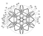
- the medical device is a front view and the living tissue is a cross-sectional view showing a state in which the dilated body is deployed and placed in the interatrial septum.
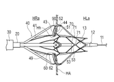
- the medical device is a front view and the living tissue is a cross-sectional view, respectively, schematically showing the expanded state of the balloon.
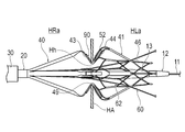
- the medical device is a front view, and the living tissue is a cross-sectional view, respectively, schematically showing the expanded state of the expanded body.
- the side of the medical device 10 to be inserted into the living body cavity is referred to as the "tip side", and the side to be operated is referred to as the "base end side”.
- the medical device expands the through hole Hh formed in the atrial septal HA of the patient's heart H, and maintains the further expanded through hole Hh at its size. It is configured so that treatment can be performed.
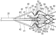
- the medical device 10 of the present embodiment includes a long outer tube 20, a storage sheath 30 for accommodating the outer tube 20, and an extension body 40 provided at the tip of the outer tube 20. It has a traction shaft 60 that pulls the expansion body 40.
- the medical device 10 further has an operation unit 80 provided at the proximal end of the outer tube 20 and an energy transfer element 90 arranged on the extension 40 to perform the above-mentioned maintenance procedure.
- the tip of the outer tube 20 is fixed to the base end of the expansion body 40.
- the base end portion of the outer pipe 20 is fixed to the operation portion 80.
- the storage sheath 30 can move forward and backward with respect to the outer pipe 20 in the axial direction (direction along the axial center).
- the storage sheath 30 can store the expansion body 40 inside the storage sheath 30 in a state of being moved to the tip end side of the outer tube 20.
- the storage sheath 30 can expose the expansion body 40 by moving from the state in which the expansion body 40 is stored to the proximal end side.
- the tow shaft 60 has a tow pipe 61 that can move forward and backward in the axial direction inside the outer pipe 20, and a spread portion 62 fixed to the tip of the tow pipe 61. ing.
- the base end portion of the tow pipe 61 is led out from the operation portion 80 to the base end side.
- a lumen is formed in the traction tube 61 along the axial direction, and a guide wire 11 and a balloon catheter 12 (see FIGS. 9 to 11) can be inserted therethrough.
- the spreading portion 62 can move inside the expanding body 40 along the axis of the expanding body 40.
- the spreading portion 62 includes a base end connecting portion 63 fixed to the tip end portion of the towing pipe 61, a plurality of base end wire rods 64 extending from the base end connecting portion 63 toward the tip end, and a base end wire rod 64 toward the tip end direction. It has a link portion 65 extending to connect the base end wire rods 64 to each other, and a plurality of auxiliary wire rods 69 extending from the link portion 65 toward the tip end. At least a part of the spread portion 62 is located on the tip side of the outer pipe 20.
- the plurality of base end wire rods 64 are evenly arranged in the circumferential direction around the axis of the expansion body 40.
- the number of the base end wire 64 is not particularly limited, but is, for example, six.
- the link portion 65 connects the base end wires 64 that are lined up in the circumferential direction and adjacent to each other, and also connects the auxiliary wires 69 that are lined up in the circumferential direction and adjacent to each other.
- the link portion 65 is formed of a honeycomb structure in which a plurality of hexagonal frames are arranged while being connected in the circumferential direction around the axis of the expansion body 40.
- the number of hexagonal frames is 6, for example, corresponding to the number of the base end wire 64 and the sub wire 69.
- the number of hexagonal frames is not particularly limited.
- the link portion 65 includes a base end link portion 66 connected to the tip end portion of the base end wire rod 64, a tip end link portion 67 connected to the base end portion of the sub wire rod 69, and a tip end link portion 67 and a base end link portion 66. It has a plurality of intermediate link portions 68 provided between the two.
- the base end link portion 66 is folded back in a zigzag manner toward the tip end side and the base end side so as to be alternately connected to the base end portion of the intermediate link portion 68 and the tip end portion of the base end wire rod 64, and the axial center of the extension body 40 is formed. It is formed in a ring shape in the center.
- the tip link portion 67 is folded back in a zigzag manner toward the tip side and the base end side so as to be alternately connected to the tip end portion of the intermediate link portion 68 and the base end portion of the sub wire 69, and is centered on the axis of the extension body 40. It is formed in a ring shape.
- the intermediate link portions 68 are evenly arranged in the circumferential direction around the axis of the expansion body 40. Each intermediate link portion 68 extends along the axis of the extension 40.
- the base end portion of the intermediate link portion 68 is connected to a portion of the proximal link portion 66 projecting toward the tip end, and the tip end portion of the intermediate link portion 68 is connected to a portion of the tip end link portion 67 projecting toward the proximal end direction.
- NS Therefore, when the connecting portion between the intermediate link portion 68 and the proximal end link portion 66 and the connecting portion between the intermediate link portion 68 and the tip end link portion 67 slide with respect to other members along the axial center, Does not get caught in other members.
- the link portion 65 formed of the honeycomb structure has a cylindrical shape, but can be expanded and contracted in the radial direction by changing the angle of the hexagonal corner.
- the link portion 65 does not have to be formed in a honeycomb structure in which hexagons are lined up, and may be formed in a lattice structure in which rhombuses are lined up, for example.
- the plurality of auxiliary wires 69 are evenly arranged in the circumferential direction around the axis of the expansion body 40.
- the number of secondary wires 69 is not particularly limited, but is, for example, six.
- Each sub-wire 69 has a linear sliding shaft 70 and an engaging portion 71 arranged at the tip of the sliding shaft 70.
- the sliding shaft 70 is slidable with respect to the expansion body 40.
- the engaging portion 71 can engage with the expanding body 40 in order to pull the expanding body 40 toward the proximal end.
- the engaging portion 71 is formed in a T shape at the tip of the sliding shaft 70, for example, and projects in two directions perpendicular to the axis of the expansion body 40 when viewed from the outside in the radial direction.
- the shape of the engaging portion 71 is not particularly limited as long as it can be engaged with the expansion body 40.
- the spreading portion 62 is formed so that the inner diameter and the outer diameter widen from the base end portion toward the tip end portion in whole or at least a part.
- the base end portion of the spreading portion 62 can be accommodated in the outer pipe 20.
- the portion of the spreading portion 62 on the tip side of the portion accommodated in the outer pipe 20 extends outward in the radial direction from the inner diameter of the outer pipe 20. Since the spreading portion 62 is formed in a net shape, it can be expanded and contracted in the radial direction.
- the spreading portion 62 is formed by subjecting a circular tube, which is a material, to laser processing. The method of forming the spreading portion 62 is not limited to this.
- FIGS. It has a plurality of sub-struts 56.
- the main struts 41 and the sub struts 56 are arranged alternately in the circumferential direction.
- the number of main struts 41 and sub-struts 56 is not particularly limited, but is, for example, six.
- a strut means a columnar member that can support a load.
- Each main strut 41 can expand and contract in the radial direction of the expansion body 40. In the natural state where no external force acts, the expansion body 40 has a form expanded in the radial direction.
- the base end portion of the main strut 41 is fixed to the tip end portion of the outer tube 20.
- the main strut 41 has a base end side main strut 42, a base end side holding strut 43, a tip side holding strut 44, a tip side main strut 45, and a tip side connecting strut 46.
- the main strut 41 has the following shapes in the deployed form.
- the base end side main strut 42 is inclined so as to increase in the radial direction from the base end portion of the extension body 40 toward the tip end direction.
- the distal end side main strut 45 is inclined so as to increase in the radial direction from the distal end side connecting strut 46 located at the distal end portion of the extension body 40 toward the proximal end direction.
- Each of the proximal main strut 42 and the distal main strut 45 extends linearly.
- the base end side holding strut 43 is inclined so as to decrease in the radial direction from the tip end portion of the base end side main strut 42 toward the tip end side.
- the base end side holding strut 43 and the base end side main strut 42 are connected by a base end side outer convex portion 47 projecting outward in the radial direction.
- the distal end side holding strut 44 is inclined so as to decrease in the radial direction from the proximal end portion of the distal end side main strut 45 toward the proximal end.
- the tip-side holding strut 44 and the tip-side main strut 45 are connected by a tip-side outer convex portion 48 protruding outward in the radial direction.
- the base end side holding strut 43 and the tip end side holding strut 44 are connected by an inward convex portion 49 protruding inward in the radial direction. It is preferable that the distance between the proximal end side holding strut 43 and the distal end side sandwiching strut 44 is slightly wider in the axial direction on the outer side than on the inner side in the radial direction in the deployed form. As a result, it is easy to dispose the biological tissue from the outside in the radial direction between the proximal side sandwiching strut 43 and the distal end side sandwiching strut 44.
- one intermediate through hole 50 is formed in the vicinity of the base end portion of the tip side main strut 45 and the tip side holding strut 44.
- the intermediate through hole 50 penetrates in the radial direction of the expansion body 40.
- the main strut 41 has two outer edge portions 51 sandwiching the intermediate through hole 50 and a back support portion 52 provided between the two outer edge portions 51.
- the back support portion 52 can face the energy transfer element 90 arranged on the proximal end side sandwiching strut 43 when the expansion body 40 contracts in the direction along the axial center.
- Each outer edge portion 51 has an arc shape in the deployed form. Therefore, a wide area for arranging the back support portion 52 and the intermediate through hole 50 can be secured between the two outer edge portions 51.
- the back support portion 52 projects between the two outer edge portions 51 from the portion of the distal end side holding strut 44 on the inner convex portion 49 side toward the proximal end portion of the distal side holding strut 44.
- the back support portion 52 is arranged between the two outer edge portions 51 at a distance from the two outer edge portions 51. Since the back support portion 52 has a cantilever-like shape in which the base end portion is fixed, it is easily bent. Therefore, the back support portion 52 can be more easily bent than the outer edge portion 51 by the force toward the tip end side received from the energy transfer element 90 arranged on the base end side holding strut 43.
- a receiving portion 53 that slidably holds the sliding shaft 70 of the towing shaft 60 is formed.
- the receiving portion 53 is a rectangular hole having a long side in the axial direction of the expansion body 40. Therefore, the direction of the long side of the receiving portion 53 is substantially perpendicular to the direction of the T-shaped engaging portion 71 of the tow shaft 60. Therefore, the receiving portion 53 engages with the engaging portion 71 without passing through the engaging portion 71 while holding the sliding shaft 70 slidably.
- the receiving portion 53 can receive a traction force from the engaging portion 71 by engaging with the engaging portion 71.
- the T-shaped engaging portion 71 of the sub wire 69 can be inserted into the receiving portion 53 by intentionally twisting the sub wire 69 90 degrees. Since the plurality of auxiliary wires 69 arranged in the circumferential direction are connected by the link portion 65, they are not easily twisted. Therefore, when the sub-wire 69 is intentionally twisted 90 degrees to insert the T-shaped engaging portion 71 into the receiving portion 53 and then the sub-wire 69 is untwisted, the engaging portion 71 receives. It becomes impossible to pass through the force unit 53.
- the position where the receiving portion 53 of the main strut 41 is formed is located on the outer side in the radial direction from the innermost surface on the inner side in the radial direction of the inner convex portion 49.
- the tip-side connecting strut 46 is located at the tip of the main strut 41.
- a plurality of tip-side connecting struts 46 are connected side by side in an annular shape in the circumferential direction.
- Each tip-side connecting strut 46 is formed in a substantially rhombic frame shape by forming a substantially rhombic tip through hole 55 penetrating in the radial direction of the expansion body 40. That is, each tip-side connecting strut 46 is formed with a lattice structure that can be changed into a quadrangle having the same length on all four sides but different angles.
- the plurality of tip-side connecting struts 46 are connected in a ring shape by joining the opposing points of the rhombus and arranging them in the circumferential direction.
- the plurality of tip-side connecting struts 46 arranged in an annular shape are connected so as to be expandable and contractible in the radial direction by utilizing the lattice structure. Therefore, the position of the receiving portion 53 that slidably holds the above-mentioned traction shaft 60 can be moved in the radial direction.
- Each sub-strut 56 is arranged between two main struts 41 adjacent in the circumferential direction and is connected to the two main struts 41.
- Each sub-strut 56 is connected to a proximal support strut 59 (supporting strut) connected to two peripheral edges 51 adjacent in the circumferential direction and to the tips of two distal main struts 45 adjacent in the circumferential direction. It has a distal end support strut 57 (supporting strut) and a merging strut 58 provided between the proximal end support strut 59 and the distal end support strut 57.
- Each tip-side support strut 57 has a confluence that connects two tip-side tilted struts 57A and two tip-side tilted struts 57A.
- the two tip-side inclined struts 57A extend from the joint portion J1 with the tip of the main strut 41 toward the proximal end so as to be inclined with the axial center of the expansion body 40 when viewed from the outside in the radial direction, and the merging struts 58 It is connected to the tip of the.
- each tip-side support strut 57 is formed longer than the linear distance between the junctions J1 with the two connected main struts 41 when viewed from the outside in the radial direction. Therefore, when the expansion body 40 becomes an expansion form that expands in the radial direction from the deployment form, the tip side support struts 57 are deformed so as to approach a linear shape so that the two joints J1 are separated from each other. can.
- Each proximal support strut 59 has two proximal inclined struts 59A.
- the two base end side inclined struts 59A extend from the joint portion J2 with the outer edge portion 51 of the main strut 41 toward the tip end so as to be inclined with the axial center of the expansion body 40 when viewed from the outside in the radial direction, and the merging struts It is connected to the base end of 58.
- the two proximal struts 59A connected to the same merging struts 58 have a plane-symmetrical shape with respect to the merging portion of the two proximal struts 59A and the plane passing through the axis of the extension 40. There is.
- each proximal support strut 59 is formed longer than the linear distance between the junction J2 with the two connected main struts 41 when viewed from the outside in the radial direction. Therefore, when the expansion body 40 becomes an expansion form that expands in the radial direction from the deployment form, each base end side support strut 59 approaches a linear shape so that the two joints J2 are separated from each other. Can be transformed.
- the merging struts 58 are evenly arranged in the circumferential direction around the axis of the expansion body 40. Each confluence strut 58 extends between the distal end support strut 57 and the proximal support strut 59 substantially parallel to the axial center of the extension 40 when viewed from the outside in the radial direction.
- a secondary strut outer protrusion 56A is formed on the proximal support strut 59 or the merging strut 58 so as to project outward in the radial direction.
- the outermost position in the radial direction of the main strut 41 of the extension 40 in the natural state is the secondary strut 56. It is located on the outer side in the radial direction rather than the outermost position in the radial direction of.
- the tip side outer convex portion 48 of the main strut 41 is the outermost in the radial direction of the sub strut 56. It is located on the outer side in the radial direction from the position of.
- the sliding shaft 70 slides along the receiving portion 53, and the engaging portion 71 engages with the receiving portion 53.
- the engaging portion 71 engaged with the receiving portion 53 can exert a traction force toward the proximal end on the receiving portion 53.
- the expanded body 40 can be compressed in the axial direction and become an expanded form that is expanded in the radial direction rather than the expanded form.
- the extended body 40 is in an expanded form, so that the proximal end side sandwiching strut 43 and the distal end side sandwiching strut 44 come close to each other.
- the main struts 41 and the sub struts 56 constituting the expansion body 40 are integrally formed by, for example, laser machining a cylinder.
- the main struts 41 and the sub struts 56 can have a thickness of 50 to 500 ⁇ m and a width of 0.1 to 2.0 mm.
- the main struts 41 and the sub struts 56 may have dimensions outside this range.
- the shapes of the main struts 41 and the sub struts 56 are not limited, and may have, for example, a circular cross-sectional shape or other cross-sectional shapes.
- the energy transfer element 90 is arranged on the proximal end side holding strut 43 so as to face the back support portion 52 of the distal end side sandwiching strut 44. Therefore, when the proximal side sandwiching strut 43 and the distal side sandwiching strut 44 sandwich the atrial septum HA, the energy from the energy transfer element 90 is transmitted from the right atrium side to the atrial septum HA. ..
- the energy transfer element 90 may be arranged on the distal end side holding strut 44, and the back support portion 52 may be arranged on the proximal end side sandwiching strut 43. In this case, the energy from the energy transfer element 90 is transmitted from the left atrium side to the atrial septal HA.
- the energy transfer element 90 is composed of, for example, a bipolar electrode that receives electrical energy from an energy supply device (not shown) which is an external device. In this case, energization is performed between the energy transfer elements 90 arranged on each main strut 41.
- the energy transfer element 90 and the energy supply device are connected by a conducting wire (not shown) coated with an insulating coating material. The conducting wire is led out to the outside via the shaft portion 20 and the operating portion 80, and is connected to the energy supply device.
- the energy transfer element 90 may also be configured as a monopolar electrode. In this case, electricity is supplied to the return electrode plate prepared outside the body. Further, the energy transfer element 90 may be a heat generating element (electrode chip) that receives high frequency electric energy from an energy supply device to generate heat. In this case, energization is performed between the energy transfer elements 90 arranged on each main strut 41. Further, the energy transfer element 90 includes microwave energy, ultrasonic energy, coherent light such as a laser, a heated fluid, a cooled fluid, an element that exerts a heating or cooling action by a chemical medium, and an element that generates frictional heat. , A heater provided with an electric wire or the like, or the like, which can be configured by an element capable of applying energy to the through hole Hh, and the specific form is not particularly limited.
- the operation unit 80 has a housing 81 gripped by the operator and a moving unit 82 that can be operated by the operator.
- the moving portion 82 is fixed to the tow shaft 60 inside the operating portion 80.
- the moving portion 82 can move back and forth with respect to the housing 81 in the axial direction of the tow shaft 60. Therefore, the operator can move the traction shaft 60 in the axial direction by moving the moving portion 82.
- the expansion body 40 can be formed of a metal material.
- the metal material for example, titanium-based (Ti—Ni, Ti—Pd, Ti—Nb—Sn, etc.) alloys, copper-based alloys, stainless steels, ⁇ -titanium steels, and Co—Cr alloys can be used. .. It is better to use an alloy having a spring property such as a nickel-titanium alloy.
- the material of the expansion body 40 is not limited to these, and may be formed of other materials.
- the storage sheath 30 and the outer tube 20 are preferably formed of a material having a certain degree of flexibility.
- a material having a certain degree of flexibility include a polyolefin such as polyethylene, polypropylene, polybutene, an ethylene-propylene copolymer, an ethylene-vinyl acetate copolymer, an ionomer, or a mixture of two or more thereof, and a soft polyvinyl chloride resin.
- fluororesins such as polyamide, polyamide elastomer, polyester, polyester elastomer, polyurethane and polytetrafluoroethylene, polyimide, PEEK, silicone rubber and latex rubber.
- the tow pipe 61 is made of, for example, a superelastic alloy such as a nickel-titanium alloy or a copper-zinc alloy, a long wire or a plate such as a metal material such as stainless steel wound in a coil shape, or from these metal materials. It can be formed of a pipe with a slit or a pipe made of a resin material having a relatively high rigidity. Further, the traction pipe 61 may have an outer coating layer coated with a resin material such as polyvinyl chloride, polyethylene, polypropylene, ethylene-propylene copolymer, or fluororesin on the outer peripheral surface thereof. As a result, the tow pipe 61 can easily move forward and backward in the axial direction inside the outer pipe 20. Further, the tow pipe 61 may have an inner coating layer coated with the above resin material (particularly fluororesin) on the inner peripheral surface thereof. This makes it easier to insert the guide wire 11 and the balloon catheter 12 into the tow tube 61.
- the spreading portion 62 can be formed of, for example, a superelastic alloy such as a nickel-titanium alloy or a copper-zinc alloy, a metal material such as stainless steel, or a resin material having a relatively high rigidity.
- This treatment method is performed on patients suffering from heart failure (left heart failure). More specifically, as shown in FIG. 7, for a patient suffering from chronic heart failure in which the blood pressure of the left atrium HLa increases due to the enlargement of the myocardium of the left ventricle of the heart H and the increase in stiffness (hardness). This is the method of treatment performed.
- the operator delivers the introducer, which is a combination of a guiding sheath and a dilator, to the vicinity of the atrial septal HA when forming the through hole Hh.
- the introducer can be delivered to the right atrium HRa via, for example, the inferior vena cava Iv.
- the introducer can be delivered using the guide wire 11.
- the operator can insert the guide wire 11 through the dilator and deliver the introducer along the guide wire 11.
- the introducer is inserted into the living body, the guide wire 11 is inserted, and the like can be performed by a known method such as using an introducer for introducing a blood vessel.
- the operator penetrates the puncture device (not shown) and the dilator from the right atrium HRa side to the left atrium HLa side to form a through hole Hh.
- the puncture device for example, a device such as a wire having a sharp tip can be used.
- the puncture device is inserted through a dilator and delivered to the atrial septal HA. After removing the guide wire 11 from the dilator, the puncture device can deliver to the atrial septal HA in place of the guide wire 11.
- the operator delivers the medical device 10 to the vicinity of the atrial septum HA along the guide wire 11 previously inserted from the right atrium HRa into the left atrium HLa via the through hole Hh. Then, a part of the tip portion of the medical device 10 passes through the through hole Hh opened in the atrial septum HA and reaches the left atrium HLa.
- the expansion body 40 is in a contracted form housed in the storage sheath 30 as shown in FIG. In the contracted form, in the natural state (deployed form), the expanding body 40 and the expanding portion 62 projecting outward in the radial direction are deformed so as to contract in the radial direction and are stored in the storage sheath 30.
- the engaging portion 71 of the tow shaft 60 is arranged away from the receiving portion 53 of the expansion body 40 on the distal end side.
- the receiving portion 53 of the expansion body 40 slides along the sliding shaft 70 of the towing shaft 60, and the engaging portion Does not touch 71. Therefore, the deformation of the expansion body 40 is not hindered by the traction shaft 60.
- the storage sheath 30 is moved to the proximal end side to expose the distal end side portion of the expansion body 40 into the left atrium HLa.
- the distal end portion of the dilated body 40 expands radially in the left atrium HLa due to its own restoring force. Since the main strut 41 on the tip side of the inwardly convex portion 49 of the expansion body 40 is supported by the sub strut 56, it is difficult to twist in the circumferential direction. Therefore, the portion on the tip end side of the expansion body 40 that is released first from the storage sheath 30 can be deployed in an appropriate shape. Next, the entire expansion body 40 is exposed by moving the storage sheath 30 toward the base end side.
- the portion of the dilated body 40 on the proximal end side expands radially in the right atrium HRa by its own restoring force. Since the portion on the tip end side of the previously deployed expansion body 40 has an appropriate shape by providing the auxiliary strut 56, the portion on the base end side of the expansion body 40 to be deployed later is also supported by the tip end side portion. Therefore, it can have an appropriate shape.
- the entire expansion body 40 is expanded, the inner convex portion 49 is arranged inside the through hole Hh. As a result, the entire expansion body 40 is expanded by its own restoring force, and is restored to the original expanded form or a form close to the expanded form.
- the atrial septal HA is arranged between the proximal side sandwiching strut 43 and the distal end side sandwiching strut 44.
- the atrial septum HA is arranged between the energy transfer element 90 and the backrest 52 in the sandwiching direction of the living tissue.
- the balloon catheter 12 has a balloon 13 (auxiliary dilator) that expands by being supplied with a fluid at the tip of a long tube.
- the surgeon brings the balloon 13 within the range where the dilator 40 is provided in the axial direction.
- the balloon 13 is arranged inside the inner convex portion 49 of the expansion body 40, that is, inside the through hole Hh.
- the tip-side connecting strut 46 located at the tip of the dilated body 40 expands in the radial direction by changing from the contracted form to the expanded form. Therefore, the balloon 13 can be arranged inside the tip portion of the expansion body 40.
- the expanding portion 62 of the tow shaft 60 is arranged outside the inner diameter of the outer pipe 20 in the radial direction. Further, the spreading portion 62 is expandable outward in the radial direction. Therefore, the spreading portion 62 can be deformed so as not to come into contact with the balloon 13 inserted inside the expansion body 40, or to escape outward in the radial direction even if the balloon 13 comes into contact with the balloon 13. Therefore, the traction shaft 60 does not prevent the balloon 13 from being placed inside the expansion body 40.
- the operator supplies the balloon catheter 12 with a fluid for expansion from the proximal end side to expand the balloon 13.
- the tip-side connecting strut 46 located at the tip of the expansion body 40 expands in the radial direction by changing from the contracted form to the expanded form.
- the expanding portion 62 of the tow shaft 60 can be deformed so as to move outward in the radial direction without contacting the balloon 13 inserted inside the expansion body 40, or even if it comes into contact with the balloon 13.
- the expansion body 40 and the traction shaft 60 do not prevent the balloon 13 from expanding inside the expansion body 40.
- the expanded balloon 13 expands the through hole Hh together with the inner convex portion 49 passing through the through hole Hh.
- the tow shaft 60 can move in the axial direction without being hindered by the expanded balloon 13.
- the tow shaft 60 is arranged so that the inwardly convex portion 49 faces the hexagonal gap of the link portion 65 so that the balloon 13 can be moved in an expanded state.
- the operator can expand the expansion body 40 by moving the traction shaft 60 toward the proximal end in the expanded state of the balloon 13.
- the operator operates the operation unit 80 to move the tow shaft 60 toward the proximal end side. As a result, as shown in FIG.
- the sliding shaft 70 slides along the receiving portion 53, and the engaging portion 71 engages with the receiving portion 53.
- the engaging portion 71 engaged with the receiving portion 53 exerts a traction force toward the proximal end on the receiving portion 53.
- the expanded body 40 is compressed in the axial direction and becomes an expanded form that is expanded in the radial direction rather than the expanded form.
- the dilated body 40 is in the expanded form, so that the proximal side sandwiching strut 43 and the distal side sandwiching strut 44 approach each other, and the atrial septum HA is sandwiched between the proximal side sandwiching strut 43 and the distal side sandwiching strut 44.
- the energy transfer element 90 and the back support portion 52 face each other.
- the traction shaft 60 is further towed while the proximal end sandwiching strut 43 and the distal end sandwiching strut 44 sandwich the atrial septum HA.
- the base end side holding strut 43 and the tip end side holding strut 44 can be further expanded, and the through hole Hh can be further expanded in the radial direction. That is, the operator can expand the through hole Hh in the radial direction by interlocking the expansion by the expansion body 40 and the expansion by the balloon 13. Therefore, even when the through hole Hh, which is the tissue to be expanded, is hard, the dilator 40 and the balloon 13 can expand the through hole Hh to a desired size. It is not necessary to further pull the traction shaft 60 after the proximal end sandwiching strut 43 and the distal end sandwiching strut 44 sandwich the atrial septum HA.
- the main strut 41 which receives the traction force from the traction shaft 60, sandwiches the atrial septum HA. At this time, the main struts 41 are supported by the proximal end side support struts 59 and the distal end side support struts 57 that are adjacent to each other in the circumferential direction.
- Each tip-side support strut 57 is formed longer than the linear distance between the two junctions J1 when viewed from the outside in the radial direction in the unfolded form before expansion. Therefore, each tip-side support strut 57 can be easily deformed so that the two joints J1 are separated from each other when the extended body 40 is in the expanded form. Therefore, the distal support strut 57 can support the main strut 41 without exerting an excessive pulling force on the main strut 41.
- each proximal support strut 59 is formed longer than the linear distance between the two junctions J2 when viewed from the outside in the radial direction in the unfolded form before expansion. Therefore, each base end side support strut 59 can be easily deformed so that the two joints J2 are separated from each other when the extended body 40 is in the expanded form. Therefore, the proximal support strut 59 can support the main strut 41 without exerting an excessive pulling force on the main strut 41.
- the main strut 41 is suppressed from twisting in the circumferential direction. Further, since the secondary strut 56 is located inside the main strut 41 in the radial direction, it is possible to prevent the linear main strut 41 from being pulled by the secondary strut 56 and bending when expanded. Therefore, the main strut 41 is less likely to disperse the force pressing the energy transfer element 90 against the tissue, and can effectively press the energy transfer element 90 against the tissue.
- the balloon 13 is expanded and then sandwiched by the expansion body 40, but the balloon 13 may be expanded after the balloon 13 is sandwiched by the expansion body 40.
- the energy transfer element 90 presses the atrial septum HA toward the distal side.
- the distal end side holding strut 44 bends the back support portion 52 toward the distal end side between the two outer edge portions 51, and the atrial septum pressed by the energy transfer element 90 between the two outer edge portions 51.
- Accept HA The two outer edge portions 51 effectively guide the energy transfer element 90 to the back support portion 52 located between the outer edge portions 51.
- the back support portion 52 receives a force from the energy transfer element 90 via the atrial septum HA and bends so as to be substantially parallel to the energy transfer element 90.
- the back support portion 52 flexibly bends and causes the atrial septum HA pushed by the energy transfer element 90 to exert a repulsive force in the direction opposite to the pushing direction of the energy transfer element 90.
- the energy transfer element 90 is in close contact with the atrial septal HA.
- the surgeon can confirm the hemodynamics by contracting the balloon 13 after expanding the through hole Hh.
- the operator delivers the hemodynamic confirmation device 100 to the right atrium HRa via the inferior vena cava Iv.
- a known echo catheter can be used as the hemodynamic confirmation device 100.
- the operator can display the echo image acquired by the hemodynamic confirmation device 100 on a display device such as a display, and confirm the amount of blood passing through the through hole Hh based on the display result.
- the surgeon performs maintenance measures to maintain the size of the through hole Hh.
- energy is applied to the edge of the through hole Hh through the energy transfer element 90, so that the edge of the through hole Hh is cauterized (heated cauterized) by the energy.
- the biological tissue near the edge of the through hole Hh is cauterized through the energy transfer element 90, a degenerated portion in which the biological tissue is denatured is formed near the edge. Since the biological tissue in the degenerated portion loses its elasticity, the through hole Hh can maintain its shape when expanded by the dilator 40 and the balloon 13.
- the surgeon drains the expansion fluid from the balloon 13 to contract the balloon 13 and then confirms the hemodynamics again.
- the operator removes the balloon catheter 12 from the medical device 10.
- the operator reduces the diameter of the expansion body 40, stores it in the storage sheath 30, and then removes it from the through hole Hh. Further, the operator removes the entire medical device 10 out of the living body and ends the procedure.
- the medical device 10 is connected to the long outer tube 20 and the tip of the outer tube 20, and expands in the radial direction by contracting along the axis of the outer tube 20.
- a possible expansion body 40 and a tow that is arranged inside the outer tube 20 and protrudes from the tip end portion of the outer tube 20 and is connected to the tip end portion of the expansion body 40 so as to be slidable with respect to the outer tube 20. It has a shaft 60 and a plurality of energy transfer elements 90 arranged on the extension body 40 to output energy, and the extension bodies 40 are arranged at intervals in the circumferential direction and are arranged at the axial center of the outer tube 20.
- each of the plurality of main struts 41 has at least one plurality of energy transfer elements 90.
- Each of the plurality of main struts 41 has a receiving portion 53 that receives a traction force from the traction shaft 60, and a portion between each of the receiving portions 53 of the plurality of main struts 41 and the energy transfer element 90.
- each of the plurality of sub-struts 56 is joined to each of the two main struts 41 adjacent to each other in the circumferential direction among the plurality of main struts 41. It has a distal support strut 57 and a proximal support strut 59 with a joint, and the distal support strut 57 and the proximal support strut 59 are each formed longer than the linear distance between the two joints. There is.
- the tip side support strut 57 and the proximal end side support strut 57 prevent the main strut 41 under the traction force from twisting in the circumferential direction when the energy transfer element 90 is pressed against the tissue. It is suppressed by 59. Therefore, in the medical device 10, the force for pressing the energy transfer element 90 against the tissue is less likely to be dispersed, and the energy transfer element 90 can be effectively pressed against the living tissue.
- the plurality of support struts extend from each of the two main struts 41 adjacent in the circumferential direction, and extend from each of the two main struts 41 in the circumferential direction with respect to the axial center when viewed from the outside in the radial direction.
- the two tilted struts having two tilted struts (tip-side tilted struts 57A or proximal-side tilted struts 59A) and a confluence connecting the two tilted struts to each other, which are connected to the confluence, , Confluent and plane symmetric with respect to the plane passing through the axis of the extension 40.
- the two plane-symmetrical inclined struts are deformed into a symmetric shape. Therefore, the forces acting on the two main struts 41 adjacent to each other in the circumferential direction from the inclined struts become equal.
- the main strut 41 it is possible to prevent the main strut 41 from being twisted in the circumferential direction. Even if the inclined strut has a curved shape, it can be regarded as an inclined strut because the tangent line of any portion is inclined with respect to the axial center.
- distal end side support struts 57 and the two proximal end side support struts 59 are arranged at a plurality of positions in the axial direction of the expansion body 40. Thereby, when the energy transfer element 90 is pressed against the tissue, the medical device 10 twists the main strut 41 in the circumferential direction, and causes a plurality of apical support struts 57 and two proximal support struts in the axial direction. It can be effectively suppressed by 59.
- distal end side support struts 57 and the proximal end side support struts 59 arranged at a plurality of positions in the axial direction of the expansion body 40 are connected.
- the distal end side support strut 57 and the proximal end side support strut 59 are connected by a merging shaft 58.
- the bending of the main struts 41 can be suppressed. Therefore, in the medical device 10, the force for pressing the energy transfer element 90 against the tissue is less likely to be dispersed, and the energy transfer element 90 can be effectively pressed against the tissue.
- the expansion body 40 has a tip side holding strut 44 and a proximal side holding strut 43 whose separation distance is narrowed by the expansion of the expanding body 40, and is between the distal end side holding strut 44 and the proximal end side holding strut 43.
- An inwardly projecting portion 49 is formed so as to project inward in the radial direction, and support struts are arranged on at least one of the tip end side and the proximal end side of the inwardly convex portion 49.
- the distal end side support strut 57 and the proximal end side support strut 59 may be directly connected without being connected by the long merging shaft 58.
- the tip end side support strut 57 and the proximal end side support strut 59 may be separately arranged without providing the merging strut 58.
- the auxiliary strut 56 provided with the support strut 54 may be provided on both the distal end side and the proximal end side of the inner convex portion 49.
- the secondary strut 56 may be provided only on the proximal end side of the inner convex portion 49.
- the two inclined struts 110 may be formed on the arc-shaped support struts 54 connected to the two main struts 41 adjacent in the circumferential direction.
- the position where the arc-shaped support strut 54 is connected to the main strut 41 is not limited to the tip side main strut 45, and is, for example, the tip side holding strut 44, the base end side holding strut 43, the base end side main strut 42, or the like. There may be.
- the traction shaft 60 engages with the inner pipe 75 that can move inside the outer pipe 20 in the axial direction and the tip portion of the inner pipe 75 is fixed. It may have a part 71.
- the engaging portion 71 is pulled in the proximal direction by the inner tube 75, and the expansion body 40 can be compressed in the axial direction.
- the expansion body 40 has a circular tubular receiving portion 53 to which a plurality of main struts 41 are connected at the tip end portion.
- the engaging portion 71 may have a ring shape having an opening so that the guide wire 11 can be inserted, but may have a shape without an opening.
- the main strut 41 of the extension body 40 may be expanded by being pulled by the traction shaft 60 and flexing outward in the radial direction without providing the distal end side sandwiching strut 44 and the proximal end side sandwiching strut 43.
- the energy transfer element 90 is arranged on the main strut 41, but may not be arranged.
- the tip end side support strut 57 of the sub-strut 56 is connected to the tip end portion of the main strut 41, and the proximal end side support strut 59 is the proximal end of the main strut 41. It may be connected to the part.
- the distal end side support strut 57 of the secondary strut 56 has two distal end side inclined struts 57A, and the proximal end side support strut 59 has only one proximal end side. It may have inclined struts 59A. Further, only one tip end side inclined strut 57A may be provided, and two base end side inclined struts 59A may be provided.
- the support strut 54 may have three inclined struts 54A which are connected while the extension body 40 is folded back in a zigzag direction in the axial direction.
- the support strut 54 has two first portions between the two joints J3 joined to each of the two main struts 41 adjacent in the circumferential direction. It may have tilted struts 54B and one second tilted strut 54C. Each of the first inclined struts 54B extends from the joint J3 in the deployed form perpendicular to the axial center when viewed from the outside in the radial direction. The second tilted strut 54C connects the two first tilted struts 54B. The second inclined strut 54C is parallel to the axial center when viewed from the outside in the radial direction in the deployed form.
- Each support strut 54 is formed in the deployed form longer than the linear distance between the two junctions J3.
- each tip-side support strut 57 is deformed so that the two joints J3 are separated from each other.
- the first inclined strut 54B is inclined from the state perpendicular to the axis when viewed from the outside in the radial direction
- the second inclined strut 54C is inclined from the state parallel to the axis when viewed from the outside in the radial direction. ..
- first inclined strut 54B and the second inclined strut 54C are inclined with the axial center when viewed from the outside in the radial direction when viewed from the outside in the radial direction in either the deployed form or the expanded form. Even in such a form, the support strut 54 can support the main strut 41 without applying an excessive pulling force to the main strut 41.
- the expansion body 40 has a circular tubular receiving portion 53 to which a plurality of main struts 41 are connected at the tip portion thereof, and each main strut 41 may have an inwardly convex portion 49.
- the traction shaft 60 has an inner pipe 75 that can move inside the outer pipe 20 in the axial direction and an engaging portion 71 fixed to the tip of the inner pipe 75, and the engaging portion 71 is formed by the inner pipe 75.
- the expansion body 40 can be compressed in the axial direction by being pulled in the proximal direction.
- Each main strut 41 has a base end side main strut 42, a base end side holding strut 43, a tip side holding strut 44, and a tip side main strut 45 from the base end side to the tip end side. There is.
- the base end side main strut 42 is inclined so as to increase in the radial direction from the tip end portion of the outer tube 20 toward the tip end direction, and the tip end side main strut 45 is directed toward the base end side from the circular tubular receiving portion 53. It is inclined so that it increases in the radial direction.
- the proximal side holding strut 43 is inclined so as to decrease in the radial direction from the distal end portion of the proximal end side main strut 42, and the distal end side sandwiching strut 44 is inclined from the proximal end portion of the distal end side main strut 45. It is inclined so that it becomes smaller in the radial direction toward the base end.
- the base end side holding strut 43 and the tip end side holding strut 44 are connected by an inward convex portion 49 protruding inward in the radial direction.
- the energy transfer element 90 is arranged at a position facing the proximal end side sandwiching strut 43 or the distal end side sandwiching strut 44 of the main strut 41 so as to sandwich the biological tissue.
- the extended body has the auxiliary strut 56 on the distal end side of the inward convex portion 49, and the proximal end side auxiliary strut 56B on the proximal end side of the inward convex portion 49.
- the tip-side support strut 57 at the tip of the secondary strut 56 is connected to each of the two tip-side main struts 45 adjacent in the circumferential direction, and the proximal-end support strut 59 at the proximal end of the secondary strut 56 is circumferentially connected. It is connected to each of the two distal pinching struts 44 adjacent to the.
- the base end side sub-struts 56B are connected to each of the two base end side main struts 42 adjacent to each other in the circumferential direction.
- the proximal side secondary strut 56B has two inclined struts 56C that are inclined with respect to the axial center when viewed from the outside in the radial direction.
- the two inclined struts 56C extend toward the proximal end while approaching from the respective proximal main struts 42 adjacent to each other in the circumferential direction, and are connected by the merging portion 56D.
- the two inclined struts 56C connected to the confluence 56D are plane-symmetric with respect to the plane passing through the confluence 56D and the axis of the extension 40.
- the medical device 10 has the accessory strut 56 and the proximal side accessory strut 56B at positions separated from each other in the axial direction of the extension body 40, so that the energy transfer element 90 is pressed against the tissue.
- the twist of the main strut 41 in the circumferential direction can be effectively suppressed.
- the base end wire rod 64 and the intermediate link portion 68 of the spreading portion 62 may be arranged in a straight line.
- the base end link portion 66 connects the connecting portions of the base end wire rod 64 and the intermediate link portion 68 to each other, and projects toward the tip end. In this case, when the spreading portion 62 is slid in the proximal direction with respect to the other member, the proximal link portion 66 does not get caught in the other member.
- the length of the spread portion 62 in the axial direction tends to be shortened, and when the balloon 13 having a small expansion dimension is used, Since the length of the spreading portion 62 in the axial direction tends to be long, it is necessary to adjust the traction amount of the traction shaft 60 according to the deviation.
- the change in the length of the spreading portion 62 in the axial direction caused by the expansion and contraction is small. Therefore, the variation in the traction amount of the traction shaft 60 due to the expansion dimension of the balloon 13 can be suppressed.
Landscapes
- Health & Medical Sciences (AREA)
- Surgery (AREA)
- Life Sciences & Earth Sciences (AREA)
- Engineering & Computer Science (AREA)
- Medical Informatics (AREA)
- General Health & Medical Sciences (AREA)
- Veterinary Medicine (AREA)
- Nuclear Medicine, Radiotherapy & Molecular Imaging (AREA)
- Biomedical Technology (AREA)
- Heart & Thoracic Surgery (AREA)
- Public Health (AREA)
- Molecular Biology (AREA)
- Animal Behavior & Ethology (AREA)
- Physics & Mathematics (AREA)
- Plasma & Fusion (AREA)
- Otolaryngology (AREA)
- Pathology (AREA)
- Dermatology (AREA)
- Oral & Maxillofacial Surgery (AREA)
- Cardiology (AREA)
- Prostheses (AREA)
- Surgical Instruments (AREA)
Abstract
Provided is a medical device in which an expanding body capable of expanding radially is inhibited from being twisted circumferentially, and an energy transfer element can be effectively pressed against biological tissue. A medical device (10) comprising: an outer tube (20); an expanding body (40) that is capable of expanding radially by being contracted along a central axis; a pulling shaft (60); and a plurality of energy transfer elements (90) disposed in the expanding body (40), wherein the expanding body (40) has a plurality of main struts (41) in which the energy transfer elements (90) are arranged, and a leading end-side support strut (57) and a base end-side support strut (59) which are linked to the main struts (41), portions of the main struts (41) between the energy transfer elements (90) and force-receiving sections (53) that receive a pulling force from the pulling shaft (60) are generally parallel to the central axis as viewed from the outside in the radial direction, the leading end-side support strut (57) and the base end-side support strut (59) are joined to respective ones of two of the main struts (41) at joint portions, and are longer than a linear distance between the two joint portions.
Description
本発明は、生体組織にエネルギーを付与する医療デバイスに関する。
The present invention relates to a medical device that imparts energy to living tissue.
近年、血管等の生体管腔に挿入して、生体の管腔や孔を拡張させるデバイスが使用される。例えば、特許文献1には、心臓の電気的な活性をマッピングするためのバスケット状の電極アセンブリを備えたカテーテルが記載されている。電極アセンブリの基端部は、外管の先端部に固定され、電極アセンブリの先端部は、外管を貫通する内管の先端部に固定されている。電極アセンブリは、内管の軸心に沿って延在しつつ径方向の外側へ凸状に湾曲する複数の線材と、各々の線材に配置される電極とを有している。複数の線材は、電極アセンブリの径方向の外側から見て、電極アセンブリの軸心と略平行である。内管を牽引することで、電極アセンブリの線材は軸心方向へ圧縮されて大きく撓み、径方向の外側へ突出する。これにより、線材に配置される電極が、生体組織に押し付けられる。
In recent years, devices that are inserted into biological lumens such as blood vessels to expand the lumens and holes of living organisms have been used. For example, Patent Document 1 describes a catheter with a basket-shaped electrode assembly for mapping the electrical activity of the heart. The base end of the electrode assembly is fixed to the tip of the outer tube, and the tip of the electrode assembly is fixed to the tip of the inner tube that penetrates the outer tube. The electrode assembly has a plurality of wires extending along the axis of the inner tube and curved outward in the radial direction, and an electrode arranged on each wire. The wires are substantially parallel to the axis of the electrode assembly when viewed from the radial outside of the electrode assembly. By pulling the inner tube, the wire rod of the electrode assembly is compressed in the axial direction and greatly flexed, and protrudes outward in the radial direction. As a result, the electrodes arranged on the wire rod are pressed against the living tissue.
径方向の外側から見て軸心と略平行である線材は、電極アセンブリの軸心方向へ圧縮されると、電極アセンブリの軸心を中心とする周方向への捩れを生じやすい。これにより、線材を圧縮する力が分散されて、組織へ効果的に力を伝えることが困難となる。
When the wire rod that is substantially parallel to the axial center when viewed from the outside in the radial direction is compressed in the axial direction of the electrode assembly, it tends to be twisted in the circumferential direction around the axial center of the electrode assembly. As a result, the force for compressing the wire rod is dispersed, and it becomes difficult to effectively transmit the force to the tissue.
本発明は、上述した課題を解決するためになされたものであり、径方向へ拡張可能な拡張体の周方向の捩れを抑制し、エネルギー伝達要素を生体組織へ効果的に押し当てることが可能な医療デバイスを提供することを目的とする。
The present invention has been made to solve the above-mentioned problems, and it is possible to suppress the twist in the circumferential direction of the extension body that can be expanded in the radial direction and effectively press the energy transfer element against the living tissue. The purpose is to provide medical devices.
上記目的を達成する本発明に係る医療デバイスは、長尺な外管と、前記外管の先端部に連結され、前記外管の軸心に沿って収縮することで径方向に拡張可能な拡張体と、前記外管の内部に配置されるとともに、前記外管の先端部から突出して前記拡張体の先端部に接続されており、前記外管に対して摺動可能な牽引シャフトと、前記拡張体に配置されてエネルギーを出力する複数のエネルギー伝達要素と、を有し、前記拡張体は、周方向に間隔を開けて配置され、前記外管の前記軸心に沿って所定長延びる複数の主ストラットと、前記複数の主ストラットに連結された複数の副ストラットと、を有し、前記複数の主ストラットにはそれぞれ、少なくとも1つの前記複数のエネルギー伝達要素が配置されており、前記複数の主ストラットはそれぞれ、前記牽引シャフトから牽引力を受ける受力部を有し、前記複数の主ストラットのそれぞれの前記受力部と前記エネルギー伝達要素の間の部位は、径方向の外側から見て軸心に略平行であり、前記複数の副ストラットはそれぞれ、前記複数の主ストラットのうち周方向に隣接する2つの主ストラットの各々に接合される2つの接合部を有する少なくとも1つの支持ストラットを有し、前記複数の支持ストラットはそれぞれ、2つの前記接合部の間の直線距離よりも長く形成されていることを特徴とする。
The medical device according to the present invention that achieves the above object is expanded in the radial direction by being connected to a long outer tube and the tip of the outer tube and contracting along the axis of the outer tube. A traction shaft that is arranged inside the outer tube, projects from the tip of the outer tube, is connected to the tip of the extension, and is slidable with respect to the outer tube, and the strut. A plurality of energy transfer elements arranged on the extension body to output energy, and the expansion body is arranged at intervals in the circumferential direction and extends a predetermined length along the axis of the outer tube. The plurality of main struts and a plurality of sub-struts connected to the plurality of main struts, and at least one of the plurality of energy transfer elements is arranged in each of the plurality of main struts. Each main strut has a receiving portion that receives a traction force from the traction shaft, and a portion between the receiving portion and the energy transfer element of each of the plurality of main struts is viewed from the outside in the radial direction. At least one support strut that is substantially parallel to the axis and has two joints, each of which is joined to each of two circumferentially adjacent main struts of the plurality of main struts. Each of the plurality of support struts is formed longer than the linear distance between the two joints.
上記のように構成した医療デバイスは、牽引力を受けた主ストラットが、エネルギー伝達要素を組織へ押し当てる際に周方向へ捩れることを、支持ストラットにより抑制される。このため、医療デバイスは、エネルギー伝達要素を組織へ押し当てる力が分散しにくくなり、エネルギー伝達要素を生体組織へ効果的に押し当てることができる。
In the medical device configured as described above, the support strut prevents the main strut under the traction force from twisting in the circumferential direction when the energy transfer element is pressed against the tissue. Therefore, in the medical device, the force of pressing the energy transfer element against the tissue is less likely to be dispersed, and the energy transfer element can be effectively pressed against the living tissue.
前記複数の支持ストラットは、周方向に隣接する2つの前記主ストラットの各々から延在し、径方向の外側から見て軸心に対して傾斜する2つの傾斜ストラットと、前記2つの傾斜ストラットが連結される合流部と、を有し、前記合流部に連結される前記2つの傾斜ストラットは、前記合流部および前記拡張体の軸心を通る面に対して面対称であってもよい。これにより、拡張体が変形する際に、面対称である2つの傾斜ストラットが対称な形状に変形する。このため、周方向に隣接する2つの主ストラットに傾斜ストラットから作用する力が均等になる。したがって、主ストラットに周方向への捩れが発生することを抑制できる。
The plurality of support struts extend from each of the two main struts adjacent in the circumferential direction, and the two inclined struts extending with respect to the axial center when viewed from the outside in the radial direction and the two inclined struts The two inclined struts having a confluence portion and being connected to the confluence portion may be plane-symmetric with respect to a plane passing through the confluence portion and the axial center of the extension body. As a result, when the extension body is deformed, the two plane-symmetrical inclined struts are deformed into a symmetric shape. Therefore, the forces acting on the two main struts adjacent to each other in the circumferential direction from the inclined struts become equal. Therefore, it is possible to prevent the main strut from being twisted in the circumferential direction.
前記拡張体の軸心方向の複数の位置に、前記支持ストラットが配置されてもよい。これにより、医療デバイスは、エネルギー伝達要素を組織へ押し当てる際に、主ストラットの周方向への捩れを、軸心方向の複数の支持ストラットによって効果的に抑制できる。
The support struts may be arranged at a plurality of positions in the axial direction of the extension body. This allows the medical device to effectively suppress the circumferential twist of the main struts by a plurality of axial support struts as the energy transfer element is pressed against the tissue.
前記拡張体の軸心方向の複数の位置に配置される複数の前記支持ストラットは、連結されてもよい。これにより、医療デバイスは、エネルギー伝達要素を組織へ押し当てる際に、主ストラットの周方向への捩れを、軸心方向に並んで連結される複数の支持ストラットによって効果的に抑制できる。また、軸心方向の複数の位置に配置される支持ストラット同士が連結されることで、主ストラットの撓みを抑制できる。このため、医療デバイスは、エネルギー伝達要素を組織へ押し当てる力が分散しにくくなり、エネルギー伝達要素を組織へ効果的に押し当てることができる。
The plurality of support struts arranged at a plurality of positions in the axial direction of the extension body may be connected. This allows the medical device to effectively suppress the circumferential twist of the main struts when pressing the energy transfer element against the tissue by a plurality of support struts connected side by side in the axial direction. Further, by connecting the support struts arranged at a plurality of positions in the axial direction, the bending of the main struts can be suppressed. Therefore, in the medical device, the force for pressing the energy transfer element against the tissue is less likely to be dispersed, and the energy transfer element can be effectively pressed against the tissue.
前記拡張体は、当該拡張体が拡張することで離間距離が狭まる先端側挟持ストラットおよび基端側挟持ストラットを有し、前記先端側挟持ストラットおよび前記基端側挟持ストラットの間に径方向の内側へ突出する内凸部が形成され、前記支持ストラットは、前記内凸部よりも先端側または基端側の少なくとも一方に配置されてもよい。これにより、先端側挟持ストラットおよび基端側挟持ストラットが、支持ストラットにより周方向へ捩れにくくなる。このため、先端側挟持ストラットおよび基端側挟持ストラットにより生体組織を把持する力が分散しにくくなり、組織を効果的に把持できる。
The extended body has a tip side holding strut and a proximal side holding strut whose separation distance is narrowed by expanding the extended body, and is radially inside between the distal side holding strut and the proximal side holding strut. An inwardly projecting portion is formed, and the support strut may be arranged on at least one of the distal end side and the proximal end side of the inwardly convex portion. As a result, the tip side holding strut and the base end side holding strut are less likely to be twisted in the circumferential direction by the support strut. Therefore, the force for gripping the biological tissue is less likely to be dispersed by the distal end side sandwiching strut and the proximal end side sandwiching strut, and the tissue can be effectively gripped.
以下、図面を参照して、本発明の実施の形態を説明する。なお、図面の寸法比率は、説明の都合上、誇張されて実際の比率とは異なる場合がある。また、本明細書では、医療デバイス10の生体内腔に挿入する側を「先端側」、操作する側を「基端側」と称することとする。
Hereinafter, embodiments of the present invention will be described with reference to the drawings. The dimensional ratios in the drawings may be exaggerated and differ from the actual ratios for convenience of explanation. Further, in the present specification, the side of the medical device 10 to be inserted into the living body cavity is referred to as the "tip side", and the side to be operated is referred to as the "base end side".
本実施形態に係る医療デバイスは、図7に示すように、患者の心臓Hの心房中隔HAに形成された貫通孔Hhを拡張し、さらに拡張した貫通孔Hhをその大きさに維持する維持処置を行うことができるように構成されている。
As shown in FIG. 7, the medical device according to the present embodiment expands the through hole Hh formed in the atrial septal HA of the patient's heart H, and maintains the further expanded through hole Hh at its size. It is configured so that treatment can be performed.
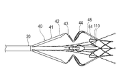
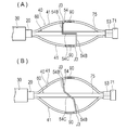
図1および2に示すように、本実施形態の医療デバイス10は、長尺な外管20と、外管20を収納する収納シース30と、外管20の先端部に設けられる拡張体40と、拡張体40を牽引する牽引シャフト60とを有している。医療デバイス10は、さらに、外管20の基端部に設けられる操作部80と、拡張体40に配置されて、前述の維持処置を行うためのエネルギー伝達要素90とを有している。
As shown in FIGS. 1 and 2, the medical device 10 of the present embodiment includes a long outer tube 20, a storage sheath 30 for accommodating the outer tube 20, and an extension body 40 provided at the tip of the outer tube 20. It has a traction shaft 60 that pulls the expansion body 40. The medical device 10 further has an operation unit 80 provided at the proximal end of the outer tube 20 and an energy transfer element 90 arranged on the extension 40 to perform the above-mentioned maintenance procedure.
外管20の先端部は、拡張体40の基端部に固定されている。外管20の基端部は、操作部80に固定されている。
The tip of the outer tube 20 is fixed to the base end of the expansion body 40. The base end portion of the outer pipe 20 is fixed to the operation portion 80.
収納シース30は、外管20に対して軸心方向(軸心に沿う方向)に進退移動可能である。収納シース30は、外管20の先端側に移動した状態で、その内部に拡張体40を収納することができる。収納シース30は、拡張体40を収納した状態から、基端側に移動することで、拡張体40を露出させることができる。
The storage sheath 30 can move forward and backward with respect to the outer pipe 20 in the axial direction (direction along the axial center). The storage sheath 30 can store the expansion body 40 inside the storage sheath 30 in a state of being moved to the tip end side of the outer tube 20. The storage sheath 30 can expose the expansion body 40 by moving from the state in which the expansion body 40 is stored to the proximal end side.
牽引シャフト60は、図2~4に示すように、外管20の内部を軸心方向に進退移動可能な牽引管61と、牽引管61の先端部に固定された広がり部62とを有している。牽引管61の基端部は、操作部80より基端側に導出されている。牽引管61には、軸心方向に沿ってルーメンが形成されており、ガイドワイヤ11やバルーンカテーテル12(図9~11を参照)を挿通させることができる。
As shown in FIGS. 2 to 4, the tow shaft 60 has a tow pipe 61 that can move forward and backward in the axial direction inside the outer pipe 20, and a spread portion 62 fixed to the tip of the tow pipe 61. ing. The base end portion of the tow pipe 61 is led out from the operation portion 80 to the base end side. A lumen is formed in the traction tube 61 along the axial direction, and a guide wire 11 and a balloon catheter 12 (see FIGS. 9 to 11) can be inserted therethrough.
広がり部62は、拡張体40の内部を拡張体40の軸心に沿って移動可能である。広がり部62は、牽引管61の先端部に固定される基端連結部63と、基端連結部63から先端方向へ延在する複数の基端線材64と、基端線材64から先端方向へ延在して基端線材64同士を連結するリンク部65と、リンク部65から先端方向へ延在する複数の副線材69とを有している。広がり部62の少なくとも一部は、外管20よりも先端側に位置している。
The spreading portion 62 can move inside the expanding body 40 along the axis of the expanding body 40. The spreading portion 62 includes a base end connecting portion 63 fixed to the tip end portion of the towing pipe 61, a plurality of base end wire rods 64 extending from the base end connecting portion 63 toward the tip end, and a base end wire rod 64 toward the tip end direction. It has a link portion 65 extending to connect the base end wire rods 64 to each other, and a plurality of auxiliary wire rods 69 extending from the link portion 65 toward the tip end. At least a part of the spread portion 62 is located on the tip side of the outer pipe 20.
複数の基端線材64は、拡張体40の軸心を中心に周方向に均等に並んでいる。基端線材64の数は、特に限定されないが、例えば6本である。
The plurality of base end wire rods 64 are evenly arranged in the circumferential direction around the axis of the expansion body 40. The number of the base end wire 64 is not particularly limited, but is, for example, six.
リンク部65は、周方向に並んで隣接する基端線材64同士を連結するとともに、周方向に並んで隣接する副線材69同士を連結する。リンク部65は、六角形である複数の枠を、拡張体40の軸心を中心に周方向に連結しつつ並べたハニカム構造で形成されている。六角形の枠の数は、例えば、基端線材64および副線材69の数に対応して6本である。なお、六角形の枠の数は、特に限定されない。
The link portion 65 connects the base end wires 64 that are lined up in the circumferential direction and adjacent to each other, and also connects the auxiliary wires 69 that are lined up in the circumferential direction and adjacent to each other. The link portion 65 is formed of a honeycomb structure in which a plurality of hexagonal frames are arranged while being connected in the circumferential direction around the axis of the expansion body 40. The number of hexagonal frames is 6, for example, corresponding to the number of the base end wire 64 and the sub wire 69. The number of hexagonal frames is not particularly limited.
リンク部65は、基端線材64の先端部に連結される基端リンク部66と、副線材69の基端部に連結される先端リンク部67と、先端リンク部67および基端リンク部66の間に設けられる複数の中間リンク部68とを有している。
The link portion 65 includes a base end link portion 66 connected to the tip end portion of the base end wire rod 64, a tip end link portion 67 connected to the base end portion of the sub wire rod 69, and a tip end link portion 67 and a base end link portion 66. It has a plurality of intermediate link portions 68 provided between the two.
基端リンク部66は、中間リンク部68の基端部および基端線材64の先端部と交互に連結するように、先端側および基端側へジグザグに折り返しつつ、拡張体40の軸心を中心に環状に形成される。
The base end link portion 66 is folded back in a zigzag manner toward the tip end side and the base end side so as to be alternately connected to the base end portion of the intermediate link portion 68 and the tip end portion of the base end wire rod 64, and the axial center of the extension body 40 is formed. It is formed in a ring shape in the center.
先端リンク部67は、中間リンク部68の先端部および副線材69の基端部と交互に連結するように、先端側および基端側へジグザグに折り返しつつ、拡張体40の軸心を中心に環状に形成される。
The tip link portion 67 is folded back in a zigzag manner toward the tip side and the base end side so as to be alternately connected to the tip end portion of the intermediate link portion 68 and the base end portion of the sub wire 69, and is centered on the axis of the extension body 40. It is formed in a ring shape.
中間リンク部68は、拡張体40の軸心を中心に周方向に均等に並んでいる。各々の中間リンク部68は、拡張体40の軸心に沿って延在する。中間リンク部68の基端部は、基端リンク部66の先端方向へ突出する部位に連結され、中間リンク部68の先端部は、先端リンク部67の基端方向へ突出する部位に連結される。このため、中間リンク部68と基端リンク部66の連結部位、および、中間リンク部68と先端リンク部67の連結部位は、軸心に沿って他の部材に対して摺動する際に、他の部材に引っ掛からない。
The intermediate link portions 68 are evenly arranged in the circumferential direction around the axis of the expansion body 40. Each intermediate link portion 68 extends along the axis of the extension 40. The base end portion of the intermediate link portion 68 is connected to a portion of the proximal link portion 66 projecting toward the tip end, and the tip end portion of the intermediate link portion 68 is connected to a portion of the tip end link portion 67 projecting toward the proximal end direction. NS. Therefore, when the connecting portion between the intermediate link portion 68 and the proximal end link portion 66 and the connecting portion between the intermediate link portion 68 and the tip end link portion 67 slide with respect to other members along the axial center, Does not get caught in other members.
ハニカム構造で形成されたリンク部65は、筒状でありつつ、六角形の角の角度を変えることで、径方向へ拡張および収縮が可能である。なお、リンク部65は、六角形が並ぶハニカム構造で形成されなくてもよく、例えば菱形が並ぶラチス構造で形成されてもよい。
The link portion 65 formed of the honeycomb structure has a cylindrical shape, but can be expanded and contracted in the radial direction by changing the angle of the hexagonal corner. The link portion 65 does not have to be formed in a honeycomb structure in which hexagons are lined up, and may be formed in a lattice structure in which rhombuses are lined up, for example.
複数の副線材69は、拡張体40の軸心を中心に周方向に均等に並んでいる。副線材69の数は、特に限定されないが、例えば6本である。各々の副線材69は、線状である摺動シャフト70と、摺動シャフト70の先端部に配置される係合部71とを有している。摺動シャフト70は、拡張体40に対して摺動可能である。係合部71は、拡張体40を基端方向へ牽引するために、拡張体40と係合可能である。係合部71は、例えば、摺動シャフト70の先端にT字状に形成され、径方向の外側から見て拡張体40の軸心に対して垂直な2方向へ突出している。なお、係合部71の形状は、拡張体40に係合可能であれば、特に限定されない。
The plurality of auxiliary wires 69 are evenly arranged in the circumferential direction around the axis of the expansion body 40. The number of secondary wires 69 is not particularly limited, but is, for example, six. Each sub-wire 69 has a linear sliding shaft 70 and an engaging portion 71 arranged at the tip of the sliding shaft 70. The sliding shaft 70 is slidable with respect to the expansion body 40. The engaging portion 71 can engage with the expanding body 40 in order to pull the expanding body 40 toward the proximal end. The engaging portion 71 is formed in a T shape at the tip of the sliding shaft 70, for example, and projects in two directions perpendicular to the axis of the expansion body 40 when viewed from the outside in the radial direction. The shape of the engaging portion 71 is not particularly limited as long as it can be engaged with the expansion body 40.
広がり部62は、全体または少なくとも一部が、基端部から先端方向へ向かって内径および外径が広がるように形成されている。広がり部62の基端部は、外管20に収容可能である。そして、広がり部62の外管20に収容される部位よりも先端側の部位は、外管20の内径よりも径方向の外側へ広がっている。広がり部62は、網状に形成されるため、径方向へ拡張および収縮可能である。広がり部62は、素材である円管にレーザー加工を施すことにより形成される。なお、広がり部62の形成方法は、これに限定されない。
The spreading portion 62 is formed so that the inner diameter and the outer diameter widen from the base end portion toward the tip end portion in whole or at least a part. The base end portion of the spreading portion 62 can be accommodated in the outer pipe 20. The portion of the spreading portion 62 on the tip side of the portion accommodated in the outer pipe 20 extends outward in the radial direction from the inner diameter of the outer pipe 20. Since the spreading portion 62 is formed in a net shape, it can be expanded and contracted in the radial direction. The spreading portion 62 is formed by subjecting a circular tube, which is a material, to laser processing. The method of forming the spreading portion 62 is not limited to this.
拡張体40は、図2、3および5に示すように、拡張体40の軸心を中心に周方向に並ぶ複数の主ストラット41と、周方向に隣接する主ストラット41の間に配置される複数の副ストラット56とを有している。主ストラット41および副ストラット56は、周方向に交互に配置されている。主ストラット41および副ストラット56の数は、特に限定されないが、例えば6本である。ストラットとは、荷重を支えることができる柱状の部材を意味する。
As shown in FIGS. It has a plurality of sub-struts 56. The main struts 41 and the sub struts 56 are arranged alternately in the circumferential direction. The number of main struts 41 and sub-struts 56 is not particularly limited, but is, for example, six. A strut means a columnar member that can support a load.
各々の主ストラット41は、拡張体40の径方向に拡張および収縮可能である。外力が作用しない自然状態において、拡張体40は径方向へ展開した形態となる。主ストラット41の基端部は、外管20の先端部に固定されている。主ストラット41は、基端側主ストラット42と、基端側挟持ストラット43と、先端側挟持ストラット44と、先端側主ストラット45と、先端側連結ストラット46とを有している。主ストラット41は、展開形態において、以下の形状を有している。
Each main strut 41 can expand and contract in the radial direction of the expansion body 40. In the natural state where no external force acts, the expansion body 40 has a form expanded in the radial direction. The base end portion of the main strut 41 is fixed to the tip end portion of the outer tube 20. The main strut 41 has a base end side main strut 42, a base end side holding strut 43, a tip side holding strut 44, a tip side main strut 45, and a tip side connecting strut 46. The main strut 41 has the following shapes in the deployed form.
基端側主ストラット42は、拡張体40の基端部から先端方向に向かって径方向へ大きくなるように傾斜している。先端側主ストラット45は、拡張体40の先端部に位置する先端側連結ストラット46から基端方向に向かって径方向へ大きくなるように傾斜している。基端側主ストラット42および先端側主ストラット45の各々は、直線的に延在している。
The base end side main strut 42 is inclined so as to increase in the radial direction from the base end portion of the extension body 40 toward the tip end direction. The distal end side main strut 45 is inclined so as to increase in the radial direction from the distal end side connecting strut 46 located at the distal end portion of the extension body 40 toward the proximal end direction. Each of the proximal main strut 42 and the distal main strut 45 extends linearly.
基端側挟持ストラット43は、基端側主ストラット42の先端部から先端方向に向かって径方向へ小さくなるように傾斜している。基端側挟持ストラット43と基端側主ストラット42は、径方向の外側へ突出する基端側外凸部47で連結されている。先端側挟持ストラット44は、先端側主ストラット45の基端部から基端方向に向かって径方向へ小さくなるように傾斜している。先端側挟持ストラット44と先端側主ストラット45は、径方向の外側へ突出する先端側外凸部48で連結されている。基端側挟持ストラット43と先端側挟持ストラット44は、径方向の内側へ突出する内凸部49で連結されている。基端側挟持ストラット43と先端側挟持ストラット44の間の間隔は、展開形態において、径方向の内側よりも外側において軸心方向に多少大きく開いていることが好ましい。これにより、基端側挟持ストラット43と先端側挟持ストラット44の間に、径方向の外側から生体組織を配置することが容易である。
The base end side holding strut 43 is inclined so as to decrease in the radial direction from the tip end portion of the base end side main strut 42 toward the tip end side. The base end side holding strut 43 and the base end side main strut 42 are connected by a base end side outer convex portion 47 projecting outward in the radial direction. The distal end side holding strut 44 is inclined so as to decrease in the radial direction from the proximal end portion of the distal end side main strut 45 toward the proximal end. The tip-side holding strut 44 and the tip-side main strut 45 are connected by a tip-side outer convex portion 48 protruding outward in the radial direction. The base end side holding strut 43 and the tip end side holding strut 44 are connected by an inward convex portion 49 protruding inward in the radial direction. It is preferable that the distance between the proximal end side holding strut 43 and the distal end side sandwiching strut 44 is slightly wider in the axial direction on the outer side than on the inner side in the radial direction in the deployed form. As a result, it is easy to dispose the biological tissue from the outside in the radial direction between the proximal side sandwiching strut 43 and the distal end side sandwiching strut 44.
主ストラット41は、先端側主ストラット45の基端部および先端側挟持ストラット44の付近に、1つの中間貫通孔50が形成されている。中間貫通孔50は、拡張体40の径方向へ貫通している。そして、主ストラット41は、中間貫通孔50を挟む2つの外縁部51と、2つの外縁部51の間に設けられる背当て部52とを有している。背当て部52は、拡張体40の軸心に沿う方向への収縮時に、基端側挟持ストラット43に配置されるエネルギー伝達要素90と対向可能である。各々の外縁部51は、展開形態において、円弧形状となっている。このため、2つの外縁部51の間に、背当て部52や中間貫通孔50を配置するための広い領域を確保できる。
In the main strut 41, one intermediate through hole 50 is formed in the vicinity of the base end portion of the tip side main strut 45 and the tip side holding strut 44. The intermediate through hole 50 penetrates in the radial direction of the expansion body 40. The main strut 41 has two outer edge portions 51 sandwiching the intermediate through hole 50 and a back support portion 52 provided between the two outer edge portions 51. The back support portion 52 can face the energy transfer element 90 arranged on the proximal end side sandwiching strut 43 when the expansion body 40 contracts in the direction along the axial center. Each outer edge portion 51 has an arc shape in the deployed form. Therefore, a wide area for arranging the back support portion 52 and the intermediate through hole 50 can be secured between the two outer edge portions 51.
背当て部52は、2つの外縁部51の間で、先端側挟持ストラット44の内凸部49側の部位から先端側挟持ストラット44の基端部へ向かって突出している。背当て部52は、2つの外縁部51の間に、2つの外縁部51から間隔を空けて配置される。背当て部52は、基端部が固定された片持ち梁状の形態であるため、撓みやすい。このため、背当て部52は、基端側挟持ストラット43に配置されるエネルギー伝達要素90から受ける先端側へ向かう力によって、外縁部51よりも容易に撓むことができる。
The back support portion 52 projects between the two outer edge portions 51 from the portion of the distal end side holding strut 44 on the inner convex portion 49 side toward the proximal end portion of the distal side holding strut 44. The back support portion 52 is arranged between the two outer edge portions 51 at a distance from the two outer edge portions 51. Since the back support portion 52 has a cantilever-like shape in which the base end portion is fixed, it is easily bent. Therefore, the back support portion 52 can be more easily bent than the outer edge portion 51 by the force toward the tip end side received from the energy transfer element 90 arranged on the base end side holding strut 43.
先端側主ストラット45の先端部には、牽引シャフト60の摺動シャフト70を摺動可能に保持する受力部53が形成される。受力部53は、拡張体40の軸心方向に長辺を有する長方形の孔である。このため、受力部53の長辺の方向は、牽引シャフト60のT字形状の係合部71の方向と略垂直である。したがって、受力部53は、摺動シャフト70を摺動可能に保持しつつ、係合部71を通過させずに係合部71と係合する。受力部53は、係合部71と係合することで、係合部71から牽引力を受けることができる。なお、副線材69のT字形状の係合部71は、副線材69を意図的に90度捩じることで、受力部53に挿入可能である。周方向に並ぶ複数の副線材69は、リンク部65により連結されているため、捩れにくい。このため、副線材69を意図的に90度捩じってT字形状の係合部71を受力部53に挿入した後、副線材69の捩れを戻すと、係合部71は、受力部53を通過不能となる。主ストラット41の受力部53が形成される位置は、内凸部49の径方向内側の最内面よりも、径方向の外側に位置する。
At the tip of the tip-side main strut 45, a receiving portion 53 that slidably holds the sliding shaft 70 of the towing shaft 60 is formed. The receiving portion 53 is a rectangular hole having a long side in the axial direction of the expansion body 40. Therefore, the direction of the long side of the receiving portion 53 is substantially perpendicular to the direction of the T-shaped engaging portion 71 of the tow shaft 60. Therefore, the receiving portion 53 engages with the engaging portion 71 without passing through the engaging portion 71 while holding the sliding shaft 70 slidably. The receiving portion 53 can receive a traction force from the engaging portion 71 by engaging with the engaging portion 71. The T-shaped engaging portion 71 of the sub wire 69 can be inserted into the receiving portion 53 by intentionally twisting the sub wire 69 90 degrees. Since the plurality of auxiliary wires 69 arranged in the circumferential direction are connected by the link portion 65, they are not easily twisted. Therefore, when the sub-wire 69 is intentionally twisted 90 degrees to insert the T-shaped engaging portion 71 into the receiving portion 53 and then the sub-wire 69 is untwisted, the engaging portion 71 receives. It becomes impossible to pass through the force unit 53. The position where the receiving portion 53 of the main strut 41 is formed is located on the outer side in the radial direction from the innermost surface on the inner side in the radial direction of the inner convex portion 49.
先端側連結ストラット46は、主ストラット41の先端部に位置する。複数の先端側連結ストラット46が、周方向に環状に並んで連結されている。各々の先端側連結ストラット46は、拡張体40の径方向へ貫通する略菱形の先端貫通孔55が形成されて、略菱形の枠状に形成される。すなわち、各々の先端側連結ストラット46は、四辺の長さが同じでも角度の違う四角形に変化可能なラチス構造で形成される。複数の先端側連結ストラット46は、菱形の対向する点同士を接合して周方向に並んで環状に連結されている。このため、環状に並ぶ複数の先端側連結ストラット46は、ラチス構造を利用して、径方向へ拡張および収縮が可能に連結される。このため、前述の牽引シャフト60を摺動可能に保持する受力部53の位置は、径方向へ移動可能である。
The tip-side connecting strut 46 is located at the tip of the main strut 41. A plurality of tip-side connecting struts 46 are connected side by side in an annular shape in the circumferential direction. Each tip-side connecting strut 46 is formed in a substantially rhombic frame shape by forming a substantially rhombic tip through hole 55 penetrating in the radial direction of the expansion body 40. That is, each tip-side connecting strut 46 is formed with a lattice structure that can be changed into a quadrangle having the same length on all four sides but different angles. The plurality of tip-side connecting struts 46 are connected in a ring shape by joining the opposing points of the rhombus and arranging them in the circumferential direction. Therefore, the plurality of tip-side connecting struts 46 arranged in an annular shape are connected so as to be expandable and contractible in the radial direction by utilizing the lattice structure. Therefore, the position of the receiving portion 53 that slidably holds the above-mentioned traction shaft 60 can be moved in the radial direction.
各々の副ストラット56は、周方向に隣接する2つの主ストラット41の間に配置されて、2つの主ストラット41に連結される。各々の副ストラット56は、周方向に隣接する2つの外縁部51に連結される基端側支持ストラット59(支持ストラット)と、周方向に隣接する2つの先端側主ストラット45の先端部に連結される先端側支持ストラット57(支持ストラット)と、基端側支持ストラット59および先端側支持ストラット57の間に設けられる合流ストラット58とを有している。
Each sub-strut 56 is arranged between two main struts 41 adjacent in the circumferential direction and is connected to the two main struts 41. Each sub-strut 56 is connected to a proximal support strut 59 (supporting strut) connected to two peripheral edges 51 adjacent in the circumferential direction and to the tips of two distal main struts 45 adjacent in the circumferential direction. It has a distal end support strut 57 (supporting strut) and a merging strut 58 provided between the proximal end support strut 59 and the distal end support strut 57.
各々の先端側支持ストラット57は、2つの先端側傾斜ストラット57Aと、2つの先端側傾斜ストラット57Aを連結する合流部を有している。2つの先端側傾斜ストラット57Aは、径方向外側から見て拡張体40の軸心と傾斜するように、主ストラット41の先端部との接合部J1から基端方向へ延在し、合流ストラット58の先端部に連結される。同じ合流ストラット58に連結される2つの先端側傾斜ストラット57Aは、2つの先端側傾斜ストラット57Aの合流部および拡張体40の軸心を通る面に対して面対称な形状を有している。展開形態において、各々の先端側支持ストラット57は、径方向の外側から見て、連結される2つの主ストラット41との接合点J1の間の直線距離よりも長く形成される。このため、拡張体40が展開形態よりも径方向に拡張した拡張形態となる際に、2つの接合部J1が離れるように、各々の先端側支持ストラット57が直線的な形状に近づくように変形できる。
Each tip-side support strut 57 has a confluence that connects two tip-side tilted struts 57A and two tip-side tilted struts 57A. The two tip-side inclined struts 57A extend from the joint portion J1 with the tip of the main strut 41 toward the proximal end so as to be inclined with the axial center of the expansion body 40 when viewed from the outside in the radial direction, and the merging struts 58 It is connected to the tip of the. The two tip-side inclined struts 57A connected to the same merging strut 58 have a plane-symmetrical shape with respect to the merging portion of the two tip-side inclined struts 57A and the plane passing through the axial center of the extension body 40. In the unfolded form, each tip-side support strut 57 is formed longer than the linear distance between the junctions J1 with the two connected main struts 41 when viewed from the outside in the radial direction. Therefore, when the expansion body 40 becomes an expansion form that expands in the radial direction from the deployment form, the tip side support struts 57 are deformed so as to approach a linear shape so that the two joints J1 are separated from each other. can.
各々の基端側支持ストラット59は、2つの基端側傾斜ストラット59Aを有している。2つの基端側傾斜ストラット59Aは、径方向外側から見て拡張体40の軸心と傾斜するように、主ストラット41の外縁部51との接合部J2から先端方向へ延在し、合流ストラット58の基端部に連結される。同じ合流ストラット58に連結される2つの基端側傾斜ストラット59Aは、2つの基端側傾斜ストラット59Aの合流部および拡張体40の軸心を通る面に対して面対称な形状を有している。展開形態において、各々の基端側支持ストラット59は、径方向の外側から見て、連結される2つの主ストラット41との接合点J2の間の直線距離よりも長く形成される。このため、拡張体40が展開形態よりも径方向に拡張した拡張形態となる際に、2つの接合部J2が離れるように、各々の基端側支持ストラット59が直線的な形状に近づくように変形できる。
Each proximal support strut 59 has two proximal inclined struts 59A. The two base end side inclined struts 59A extend from the joint portion J2 with the outer edge portion 51 of the main strut 41 toward the tip end so as to be inclined with the axial center of the expansion body 40 when viewed from the outside in the radial direction, and the merging struts It is connected to the base end of 58. The two proximal struts 59A connected to the same merging struts 58 have a plane-symmetrical shape with respect to the merging portion of the two proximal struts 59A and the plane passing through the axis of the extension 40. There is. In the deployed form, each proximal support strut 59 is formed longer than the linear distance between the junction J2 with the two connected main struts 41 when viewed from the outside in the radial direction. Therefore, when the expansion body 40 becomes an expansion form that expands in the radial direction from the deployment form, each base end side support strut 59 approaches a linear shape so that the two joints J2 are separated from each other. Can be transformed.
合流ストラット58は、拡張体40の軸心を中心に周方向に均等に並んでいる。各々の合流ストラット58は、先端側支持ストラット57と基端側支持ストラット59の間で、径方向外側から見て拡張体40の軸心と略平行に延在する。副ストラット56は、基端側支持ストラット59または合流ストラット58に、径方向の外側へ突出する副ストラット外凸部56Aが形成される。
The merging struts 58 are evenly arranged in the circumferential direction around the axis of the expansion body 40. Each confluence strut 58 extends between the distal end support strut 57 and the proximal support strut 59 substantially parallel to the axial center of the extension 40 when viewed from the outside in the radial direction. In the secondary strut 56, a secondary strut outer protrusion 56A is formed on the proximal support strut 59 or the merging strut 58 so as to project outward in the radial direction.
副ストラット56が存在する部位の、いずれかの軸心方向の位置における軸心と垂直な断面において、自然状態である拡張体40の主ストラット41の径方向へ最も外側の位置は、副ストラット56の径方向へ最も外側の位置よりも径方向の外側に位置する。さらに、自然状態である拡張体40の先端側外凸部48が設けられる位置における軸心と垂直な断面において、主ストラット41の先端側外凸部48は、副ストラット56の径方向へ最も外側の位置よりも径方向の外側に位置する。
In the cross section perpendicular to the axis at any position in the axial direction of the site where the secondary strut 56 is present, the outermost position in the radial direction of the main strut 41 of the extension 40 in the natural state is the secondary strut 56. It is located on the outer side in the radial direction rather than the outermost position in the radial direction of. Further, in the cross section perpendicular to the axis at the position where the tip side outer convex portion 48 of the extended body 40 in the natural state is provided, the tip side outer convex portion 48 of the main strut 41 is the outermost in the radial direction of the sub strut 56. It is located on the outer side in the radial direction from the position of.
牽引シャフト60が基端側に移動すると、図6に示すように、摺動シャフト70が受力部53に沿って摺動し、係合部71が受力部53に係合する。受力部53に係合した係合部71は、受力部53に基端方向へ向かう牽引力を作用させることができる。これにより、拡張体40は、軸心方向へ圧縮されて、展開形態よりも径方向に拡張した拡張形態となることができる。拡張体40は、拡張形態となることで、基端側挟持ストラット43と先端側挟持ストラット44が近づく。
When the tow shaft 60 moves to the proximal end side, as shown in FIG. 6, the sliding shaft 70 slides along the receiving portion 53, and the engaging portion 71 engages with the receiving portion 53. The engaging portion 71 engaged with the receiving portion 53 can exert a traction force toward the proximal end on the receiving portion 53. As a result, the expanded body 40 can be compressed in the axial direction and become an expanded form that is expanded in the radial direction rather than the expanded form. The extended body 40 is in an expanded form, so that the proximal end side sandwiching strut 43 and the distal end side sandwiching strut 44 come close to each other.
拡張体40を構成する主ストラット41および副ストラット56は、例えば、円筒をレーザー加工することで一体的に形成される。主ストラット41および副ストラット56は、厚み50~500μm、幅0.1~2.0mmとすることができる。ただし、主ストラット41および副ストラット56は、この範囲外の寸法を有していてもよい。また、主ストラット41および副ストラット56の形状は、限定されず、例えば円形の断面形状や、それ以外の断面形状を有していてもよい。
The main struts 41 and the sub struts 56 constituting the expansion body 40 are integrally formed by, for example, laser machining a cylinder. The main struts 41 and the sub struts 56 can have a thickness of 50 to 500 μm and a width of 0.1 to 2.0 mm. However, the main struts 41 and the sub struts 56 may have dimensions outside this range. The shapes of the main struts 41 and the sub struts 56 are not limited, and may have, for example, a circular cross-sectional shape or other cross-sectional shapes.
エネルギー伝達要素90は、図2、9に示すように、基端側挟持ストラット43に、先端側挟持ストラット44の背当て部52に対向して配置される。このため、基端側挟持ストラット43および先端側挟持ストラット44が心房中隔HAを挟持する際には、エネルギー伝達要素90からのエネルギーは、心房中隔HAに対して右心房側から伝達される。なお、エネルギー伝達要素90は、先端側挟持ストラット44に配置され、背当て部52は、基端側挟持ストラット43に配置されてもよい。この場合、エネルギー伝達要素90からのエネルギーは、心房中隔HAに対して左心房側から伝達される。
As shown in FIGS. 2 and 9, the energy transfer element 90 is arranged on the proximal end side holding strut 43 so as to face the back support portion 52 of the distal end side sandwiching strut 44. Therefore, when the proximal side sandwiching strut 43 and the distal side sandwiching strut 44 sandwich the atrial septum HA, the energy from the energy transfer element 90 is transmitted from the right atrium side to the atrial septum HA. .. The energy transfer element 90 may be arranged on the distal end side holding strut 44, and the back support portion 52 may be arranged on the proximal end side sandwiching strut 43. In this case, the energy from the energy transfer element 90 is transmitted from the left atrium side to the atrial septal HA.
エネルギー伝達要素90は、例えば、外部装置であるエネルギー供給装置(図示しない)から電気エネルギーを受けるバイポーラ電極で構成される。この場合、各主ストラット41に配置されたエネルギー伝達要素90間で通電がなされる。エネルギー伝達要素90とエネルギー供給装置とは、絶縁性被覆材で被覆された導線(図示しない)により接続される。導線は、シャフト部20及び操作部80を介して外部に導出され、エネルギー供給装置に接続される。
The energy transfer element 90 is composed of, for example, a bipolar electrode that receives electrical energy from an energy supply device (not shown) which is an external device. In this case, energization is performed between the energy transfer elements 90 arranged on each main strut 41. The energy transfer element 90 and the energy supply device are connected by a conducting wire (not shown) coated with an insulating coating material. The conducting wire is led out to the outside via the shaft portion 20 and the operating portion 80, and is connected to the energy supply device.
エネルギー伝達要素90は、他にも、モノポーラ電極として構成されていてもよい。この場合、体外に用意される対極板との間で通電がなされる。また、エネルギー伝達要素90は、エネルギー供給装置から高周波の電気エネルギーを受給して発熱する発熱素子(電極チップ)でもよい。この場合、各主ストラット41に配置されたエネルギー伝達要素90間で通電がなされる。さらに、エネルギー伝達要素90は、マイクロ波エネルギー、超音波エネルギー、レーザー等のコヒーレント光、加熱した流体、冷却された流体、化学的な媒体により加熱や冷却作用を及ぼすもの、摩擦熱を生じさせるもの、電線等を備えるヒーター等のように、貫通孔Hhに対してエネルギーを付与可能な要素により構成することができ、具体的な形態は特に限定されない。
The energy transfer element 90 may also be configured as a monopolar electrode. In this case, electricity is supplied to the return electrode plate prepared outside the body. Further, the energy transfer element 90 may be a heat generating element (electrode chip) that receives high frequency electric energy from an energy supply device to generate heat. In this case, energization is performed between the energy transfer elements 90 arranged on each main strut 41. Further, the energy transfer element 90 includes microwave energy, ultrasonic energy, coherent light such as a laser, a heated fluid, a cooled fluid, an element that exerts a heating or cooling action by a chemical medium, and an element that generates frictional heat. , A heater provided with an electric wire or the like, or the like, which can be configured by an element capable of applying energy to the through hole Hh, and the specific form is not particularly limited.
操作部80は、図1に示すように、術者が把持する筐体81と、術者が操作可能な移動部82とを有している。移動部82は、操作部80の内部において、牽引シャフト60に固定されている。移動部82は、筐体81に対して、牽引シャフト60の軸心方向へ進退移動可能である。したがって、術者は、移動部82を移動させることで、牽引シャフト60を軸心方向へ移動させることができる。
As shown in FIG. 1, the operation unit 80 has a housing 81 gripped by the operator and a moving unit 82 that can be operated by the operator. The moving portion 82 is fixed to the tow shaft 60 inside the operating portion 80. The moving portion 82 can move back and forth with respect to the housing 81 in the axial direction of the tow shaft 60. Therefore, the operator can move the traction shaft 60 in the axial direction by moving the moving portion 82.
拡張体40は、金属材料で形成することができる。この金属材料としては、例えば、チタン系(Ti-Ni、Ti-Pd、Ti-Nb-Sn等)の合金、銅系の合金、ステンレス鋼、βチタン鋼、Co-Cr合金を用いることができる。なお、ニッケルチタン合金等のバネ性を有する合金等を用いるとよりよい。ただし、拡張体40の材料はこれらに限られず、その他の材料で形成してもよい。
The expansion body 40 can be formed of a metal material. As the metal material, for example, titanium-based (Ti—Ni, Ti—Pd, Ti—Nb—Sn, etc.) alloys, copper-based alloys, stainless steels, β-titanium steels, and Co—Cr alloys can be used. .. It is better to use an alloy having a spring property such as a nickel-titanium alloy. However, the material of the expansion body 40 is not limited to these, and may be formed of other materials.
収納シース30および外管20は、ある程度の可撓性を有する材料により形成されるのが好ましい。そのような材料としては、例えば、ポリエチレン、ポリプロピレン、ポリブテン、エチレン-プロピレン共重合体、エチレン-酢酸ビニル共重合体、アイオノマー、あるいはこれら二種以上の混合物等のポリオレフィンや、軟質ポリ塩化ビニル樹脂、ポリアミド、ポリアミドエラストマー、ポリエステル、ポリエステルエラストマー、ポリウレタン、ポリテトラフルオロエチレン等のフッ素樹脂、ポリイミド、PEEK、シリコーンゴム、ラテックスゴム等が挙げられる。
The storage sheath 30 and the outer tube 20 are preferably formed of a material having a certain degree of flexibility. Examples of such a material include a polyolefin such as polyethylene, polypropylene, polybutene, an ethylene-propylene copolymer, an ethylene-vinyl acetate copolymer, an ionomer, or a mixture of two or more thereof, and a soft polyvinyl chloride resin. Examples thereof include fluororesins such as polyamide, polyamide elastomer, polyester, polyester elastomer, polyurethane and polytetrafluoroethylene, polyimide, PEEK, silicone rubber and latex rubber.
牽引管61は、例えば、ニッケル-チタン合金、銅-亜鉛合金等の超弾性合金、ステンレス鋼等の金属材料などの長尺状の線材または板材をコイル状に巻いたもの、これらの金属材料からなるスリット入りパイプ、または、比較的剛性の高い樹脂材料の管体で形成することができる。また、牽引管61は、その外周面にポリ塩化ビニル、ポリエチレン、ポリプロピレン、エチレンープロピレン共重合体、フッ素樹脂などの樹脂材料を被覆した外被覆層を有してもよい。これにより、牽引管61が外管20の内部を軸心方向に進退移動し易くなる。また、牽引管61は、その内周面に、上記の樹脂材料(特にフッ素樹脂)を被覆した内被覆層を有してもよい。これにより、牽引管61内に、ガイドワイヤ11やバルーンカテーテル12を挿通しやすくなる。
The tow pipe 61 is made of, for example, a superelastic alloy such as a nickel-titanium alloy or a copper-zinc alloy, a long wire or a plate such as a metal material such as stainless steel wound in a coil shape, or from these metal materials. It can be formed of a pipe with a slit or a pipe made of a resin material having a relatively high rigidity. Further, the traction pipe 61 may have an outer coating layer coated with a resin material such as polyvinyl chloride, polyethylene, polypropylene, ethylene-propylene copolymer, or fluororesin on the outer peripheral surface thereof. As a result, the tow pipe 61 can easily move forward and backward in the axial direction inside the outer pipe 20. Further, the tow pipe 61 may have an inner coating layer coated with the above resin material (particularly fluororesin) on the inner peripheral surface thereof. This makes it easier to insert the guide wire 11 and the balloon catheter 12 into the tow tube 61.
広がり部62は、例えば、ニッケル-チタン合金、銅-亜鉛合金等の超弾性合金、ステンレス鋼等の金属材料、比較的剛性の高い樹脂材料などで形成することができる。
The spreading portion 62 can be formed of, for example, a superelastic alloy such as a nickel-titanium alloy or a copper-zinc alloy, a metal material such as stainless steel, or a resin material having a relatively high rigidity.
次に、本実施形態に係る医療デバイス10を使用した処置方法について説明する。本処置方法は、心不全(左心不全)に罹患した患者に対して行われる。より具体的には、図7に示すように、心臓Hの左心室の心筋が肥大化してスティッフネス(硬さ)が増すことで、左心房HLaの血圧が高まる慢性心不全に罹患した患者に対して行われる処置の方法である。
Next, a treatment method using the medical device 10 according to the present embodiment will be described. This treatment method is performed on patients suffering from heart failure (left heart failure). More specifically, as shown in FIG. 7, for a patient suffering from chronic heart failure in which the blood pressure of the left atrium HLa increases due to the enlargement of the myocardium of the left ventricle of the heart H and the increase in stiffness (hardness). This is the method of treatment performed.
術者は、貫通孔Hhの形成に際し、ガイディングシース及びダイレータが組み合わされたイントロデューサを心房中隔HA付近まで送達する。イントロデューサは、例えば、下大静脈Ivを介して右心房HRaに送達することができる。また、イントロデューサの送達は、ガイドワイヤ11を使用して行うことができる。術者は、ダイレータにガイドワイヤ11を挿通し、ガイドワイヤ11に沿わせて、イントロデューサを送達させることができる。なお、生体に対するイントロデューサの挿入、ガイドワイヤ11の挿入等は、血管導入用のイントロデューサを用いるなど、公知の方法で行うことができる。
The operator delivers the introducer, which is a combination of a guiding sheath and a dilator, to the vicinity of the atrial septal HA when forming the through hole Hh. The introducer can be delivered to the right atrium HRa via, for example, the inferior vena cava Iv. In addition, the introducer can be delivered using the guide wire 11. The operator can insert the guide wire 11 through the dilator and deliver the introducer along the guide wire 11. The introducer is inserted into the living body, the guide wire 11 is inserted, and the like can be performed by a known method such as using an introducer for introducing a blood vessel.
次に、術者は、右心房HRa側から左心房HLa側に向かって、穿刺デバイス(図示しない)およびダイレータを貫通させ、貫通孔Hhを形成する。穿刺デバイスとしては、例えば、先端が尖ったワイヤ等のデバイスを使用することができる。穿刺デバイスは、ダイレータに挿通させて心房中隔HAまで送達する。穿刺デバイスは、ダイレータからガイドワイヤ11を抜去した後、ガイドワイヤ11に代えて心房中隔HAまで送達することができる。
Next, the operator penetrates the puncture device (not shown) and the dilator from the right atrium HRa side to the left atrium HLa side to form a through hole Hh. As the puncture device, for example, a device such as a wire having a sharp tip can be used. The puncture device is inserted through a dilator and delivered to the atrial septal HA. After removing the guide wire 11 from the dilator, the puncture device can deliver to the atrial septal HA in place of the guide wire 11.
次に、術者は、予め右心房HRaから貫通孔Hhを介して左心房HLaに挿入されたガイドワイヤ11に沿って、医療デバイス10を心房中隔HA付近に送達する。そして、医療デバイス10の先端部の一部は、心房中隔HAに開けた貫通孔Hhを通過して、左心房HLaに達するようにする。医療デバイス10の挿入の際、拡張体40は、図8に示すように、収納シース30に収納された収縮形態となっている。収縮形態において、自然状態(展開形態)では径方向外側へ突出している拡張体40および広がり部62が、径方向に収縮するように変形して、収納シース30に収納される。拡張体40を収納シース30に収納する際には、牽引シャフト60の係合部71を、拡張体40の受力部53よりも先端側に離れて配置する。これにより、拡張体40が径方向に収縮することで軸心方向に伸長する際に、拡張体40の受力部53が牽引シャフト60の摺動シャフト70に沿って摺動し、係合部71に接触しない。このため、拡張体40の変形が、牽引シャフト60により妨げられない。
Next, the operator delivers the medical device 10 to the vicinity of the atrial septum HA along the guide wire 11 previously inserted from the right atrium HRa into the left atrium HLa via the through hole Hh. Then, a part of the tip portion of the medical device 10 passes through the through hole Hh opened in the atrial septum HA and reaches the left atrium HLa. When the medical device 10 is inserted, the expansion body 40 is in a contracted form housed in the storage sheath 30 as shown in FIG. In the contracted form, in the natural state (deployed form), the expanding body 40 and the expanding portion 62 projecting outward in the radial direction are deformed so as to contract in the radial direction and are stored in the storage sheath 30. When the expansion body 40 is stored in the storage sheath 30, the engaging portion 71 of the tow shaft 60 is arranged away from the receiving portion 53 of the expansion body 40 on the distal end side. As a result, when the expansion body 40 contracts in the radial direction and extends in the axial direction, the receiving portion 53 of the expansion body 40 slides along the sliding shaft 70 of the towing shaft 60, and the engaging portion Does not touch 71. Therefore, the deformation of the expansion body 40 is not hindered by the traction shaft 60.
次に、図9に示すように、収納シース30を基端側に移動させることにより、拡張体40の先端側の部分を左心房HLa内に露出させる。これにより、拡張体40のうち先端側の部分は、自己の復元力によって左心房HLa内で径方向へ展開する。なお、拡張体40内凸部49よりも先端側の主ストラット41は、副ストラット56により支持されているため、周方向へ捩れにくい。このため、収納シース30から先に放出される拡張体40の先端側の部分が、適切な形状で展開できる。次に、収納シース30を基端側に移動させることにより、拡張体40の全体を露出させる。これにより、拡張体40のうち基端側の部分が、自己の復元力によって右心房HRa内で径方向へ展開する。先に展開した拡張体40の先端側の部分が、副ストラット56が設けられることで適切な形状となるため、後に展開する拡張体40の基端側の部分も、先端側の部分に支持されて、適切な形状となることができる。拡張体40の全体が展開すると、内凸部49は、貫通孔Hhの内側に配置される。これにより、拡張体40の全体が、自己の復元力によって展開し、元の展開形態または展開形態に近い形態に復元する。この際、心房中隔HAは、基端側挟持ストラット43と先端側挟持ストラット44との間に配置される。生体組織の挟持方向において、エネルギー伝達要素90と背当て部52の間に、心房中隔HAが配置される。
Next, as shown in FIG. 9, the storage sheath 30 is moved to the proximal end side to expose the distal end side portion of the expansion body 40 into the left atrium HLa. As a result, the distal end portion of the dilated body 40 expands radially in the left atrium HLa due to its own restoring force. Since the main strut 41 on the tip side of the inwardly convex portion 49 of the expansion body 40 is supported by the sub strut 56, it is difficult to twist in the circumferential direction. Therefore, the portion on the tip end side of the expansion body 40 that is released first from the storage sheath 30 can be deployed in an appropriate shape. Next, the entire expansion body 40 is exposed by moving the storage sheath 30 toward the base end side. As a result, the portion of the dilated body 40 on the proximal end side expands radially in the right atrium HRa by its own restoring force. Since the portion on the tip end side of the previously deployed expansion body 40 has an appropriate shape by providing the auxiliary strut 56, the portion on the base end side of the expansion body 40 to be deployed later is also supported by the tip end side portion. Therefore, it can have an appropriate shape. When the entire expansion body 40 is expanded, the inner convex portion 49 is arranged inside the through hole Hh. As a result, the entire expansion body 40 is expanded by its own restoring force, and is restored to the original expanded form or a form close to the expanded form. At this time, the atrial septal HA is arranged between the proximal side sandwiching strut 43 and the distal end side sandwiching strut 44. The atrial septum HA is arranged between the energy transfer element 90 and the backrest 52 in the sandwiching direction of the living tissue.
次に、術者は、牽引管61の基端側からルーメンに、バルーンカテーテル12を挿入する。バルーンカテーテル12は、長尺な管体の先端部に、流体を供給されることで拡張するバルーン13(補助拡張体)を有している。術者は、バルーン13を、軸心方向において拡張体40が設けられる範囲内に到達させる。バルーン13は、拡張体40の内凸部49の内側、すなわち、貫通孔Hhの内側に配置される。拡張体40の先端部に位置する先端側連結ストラット46は、収縮形態から展開形態となることで径方向へ拡張している。このため、拡張体40の先端部の内部に、バルーン13を配置することができる。また、牽引シャフト60の広がり部62は、外管20の内径よりも径方向の外側に配置される。さらに、広がり部62は、径方向の外側に拡張可能である。このため、広がり部62は、拡張体40の内部に挿入されたバルーン13に接触せず、または接触しても径方向の外側へ逃げるように変形できる。このため、牽引シャフト60は、バルーン13を拡張体40の内部に配置することを妨げない。
Next, the operator inserts the balloon catheter 12 into the lumen from the proximal end side of the traction tube 61. The balloon catheter 12 has a balloon 13 (auxiliary dilator) that expands by being supplied with a fluid at the tip of a long tube. The surgeon brings the balloon 13 within the range where the dilator 40 is provided in the axial direction. The balloon 13 is arranged inside the inner convex portion 49 of the expansion body 40, that is, inside the through hole Hh. The tip-side connecting strut 46 located at the tip of the dilated body 40 expands in the radial direction by changing from the contracted form to the expanded form. Therefore, the balloon 13 can be arranged inside the tip portion of the expansion body 40. Further, the expanding portion 62 of the tow shaft 60 is arranged outside the inner diameter of the outer pipe 20 in the radial direction. Further, the spreading portion 62 is expandable outward in the radial direction. Therefore, the spreading portion 62 can be deformed so as not to come into contact with the balloon 13 inserted inside the expansion body 40, or to escape outward in the radial direction even if the balloon 13 comes into contact with the balloon 13. Therefore, the traction shaft 60 does not prevent the balloon 13 from being placed inside the expansion body 40.
次に、術者は、図10に示すように、バルーンカテーテル12に基端側から拡張用の流体を供給し、バルーン13を拡張させる。このとき、拡張体40の先端部に位置する先端側連結ストラット46は、収縮形態から展開形態となることで径方向へ拡張している。そして、牽引シャフト60の広がり部62は、拡張体40の内部に挿入されたバルーン13に接触せず、または接触しても径方向の外側へ移動するように変形できる。これにより、拡張体40および牽引シャフト60は、拡張体40の内部におけるバルーン13の拡張を妨げない。拡張したバルーン13は、貫通孔Hhを、貫通孔Hhを通る内凸部49とともに押し広げる。
Next, as shown in FIG. 10, the operator supplies the balloon catheter 12 with a fluid for expansion from the proximal end side to expand the balloon 13. At this time, the tip-side connecting strut 46 located at the tip of the expansion body 40 expands in the radial direction by changing from the contracted form to the expanded form. Then, the expanding portion 62 of the tow shaft 60 can be deformed so as to move outward in the radial direction without contacting the balloon 13 inserted inside the expansion body 40, or even if it comes into contact with the balloon 13. Thereby, the expansion body 40 and the traction shaft 60 do not prevent the balloon 13 from expanding inside the expansion body 40. The expanded balloon 13 expands the through hole Hh together with the inner convex portion 49 passing through the through hole Hh.
また、牽引シャフト60は、拡張したバルーン13に妨げられることなく、軸心方向へ移動できる。牽引シャフト60は、バルーン13を拡張させた状態で移動できるように、内凸部49が、リンク部65の六角形の隙間に向かうように配置される。これにより、牽引シャフト60が移動する際に、拡張体40の内凸部49が牽引シャフト60と接触して移動を妨げられることを抑制できる。このため、術者は、バルーン13を拡張させた状態で、牽引シャフト60を基端方向へ移動させて、拡張体40を拡張させることができる。術者は、操作部80を操作し、牽引シャフト60を基端側に移動させる。これにより、図11に示すように、摺動シャフト70が受力部53に沿って摺動し、係合部71が受力部53に係合する。受力部53に係合した係合部71は、受力部53に基端方向へ向かう牽引力を作用させる。これにより、拡張体40は、軸心方向へ圧縮されて、展開形態よりも径方向に拡張した拡張形態となる。拡張体40は、拡張形態となることで、基端側挟持ストラット43と先端側挟持ストラット44が近づき、基端側挟持ストラット43と先端側挟持ストラット44の間に心房中隔HAを挟持する。このとき、エネルギー伝達要素90と背当て部52は対向する。基端側挟持ストラット43と先端側挟持ストラット44が心房中隔HAを挟持した状態で、牽引シャフト60をさらに牽引する。これにより、基端側挟持ストラット43と先端側挟持ストラット44がさらに拡張し、貫通孔Hhを径方向にさらに押し広げることができる。すなわち、術者は、拡張体40による拡張と、バルーン13による拡張を連動させて、貫通孔Hhを径方向に押し広げることができる。このため、拡張させる対象の組織である貫通孔Hhが硬い場合であっても、拡張体40およびバルーン13は、貫通孔Hhを望ましい大きさに拡張できる。なお、基端側挟持ストラット43と先端側挟持ストラット44が心房中隔HAを挟持した後に、牽引シャフト60をさらに牽引しなくてもよい。
Further, the tow shaft 60 can move in the axial direction without being hindered by the expanded balloon 13. The tow shaft 60 is arranged so that the inwardly convex portion 49 faces the hexagonal gap of the link portion 65 so that the balloon 13 can be moved in an expanded state. As a result, when the tow shaft 60 moves, it is possible to prevent the inwardly convex portion 49 of the expansion body 40 from coming into contact with the tow shaft 60 and being hindered from moving. Therefore, the operator can expand the expansion body 40 by moving the traction shaft 60 toward the proximal end in the expanded state of the balloon 13. The operator operates the operation unit 80 to move the tow shaft 60 toward the proximal end side. As a result, as shown in FIG. 11, the sliding shaft 70 slides along the receiving portion 53, and the engaging portion 71 engages with the receiving portion 53. The engaging portion 71 engaged with the receiving portion 53 exerts a traction force toward the proximal end on the receiving portion 53. As a result, the expanded body 40 is compressed in the axial direction and becomes an expanded form that is expanded in the radial direction rather than the expanded form. The dilated body 40 is in the expanded form, so that the proximal side sandwiching strut 43 and the distal side sandwiching strut 44 approach each other, and the atrial septum HA is sandwiched between the proximal side sandwiching strut 43 and the distal side sandwiching strut 44. At this time, the energy transfer element 90 and the back support portion 52 face each other. The traction shaft 60 is further towed while the proximal end sandwiching strut 43 and the distal end sandwiching strut 44 sandwich the atrial septum HA. As a result, the base end side holding strut 43 and the tip end side holding strut 44 can be further expanded, and the through hole Hh can be further expanded in the radial direction. That is, the operator can expand the through hole Hh in the radial direction by interlocking the expansion by the expansion body 40 and the expansion by the balloon 13. Therefore, even when the through hole Hh, which is the tissue to be expanded, is hard, the dilator 40 and the balloon 13 can expand the through hole Hh to a desired size. It is not necessary to further pull the traction shaft 60 after the proximal end sandwiching strut 43 and the distal end sandwiching strut 44 sandwich the atrial septum HA.
牽引シャフト60から牽引力を受けた主ストラット41は、心房中隔HAを挟持する。この際に、主ストラット41は、周方向に隣接する基端側支持ストラット59および先端側支持ストラット57により支持される。
The main strut 41, which receives the traction force from the traction shaft 60, sandwiches the atrial septum HA. At this time, the main struts 41 are supported by the proximal end side support struts 59 and the distal end side support struts 57 that are adjacent to each other in the circumferential direction.
各々の先端側支持ストラット57は、拡張する前の展開形態において、径方向の外側から見て、2つの接合点J1の間の直線距離よりも長く形成される。このため、拡張体40が拡張形態となる際に、2つの接合部J1が離れるように、各々の先端側支持ストラット57が容易に変形できる。したがって、先端側支持ストラット57は、主ストラット41に過度な引っ張り力を作用させずに、主ストラット41を支持することができる。
Each tip-side support strut 57 is formed longer than the linear distance between the two junctions J1 when viewed from the outside in the radial direction in the unfolded form before expansion. Therefore, each tip-side support strut 57 can be easily deformed so that the two joints J1 are separated from each other when the extended body 40 is in the expanded form. Therefore, the distal support strut 57 can support the main strut 41 without exerting an excessive pulling force on the main strut 41.
また、各々の基端側支持ストラット59は、拡張する前の展開形態において、径方向の外側から見て、2つの接合点J2の間の直線距離よりも長く形成される。このため、拡張体40が拡張形態となる際に、2つの接合部J2が離れるように、各々の基端側支持ストラット59が容易に変形できる。したがって、基端側支持ストラット59は、主ストラット41に過度な引っ張り力を作用させずに、主ストラット41を支持することができる。
Further, each proximal support strut 59 is formed longer than the linear distance between the two junctions J2 when viewed from the outside in the radial direction in the unfolded form before expansion. Therefore, each base end side support strut 59 can be easily deformed so that the two joints J2 are separated from each other when the extended body 40 is in the expanded form. Therefore, the proximal support strut 59 can support the main strut 41 without exerting an excessive pulling force on the main strut 41.
このため、主ストラット41は、周方向への捩れを抑制される。さらに、副ストラット56が、主ストラット41よりも径方向の内側に位置することで、拡張する際に、直線状であった主ストラット41が副ストラット56により引っ張られて撓むことを抑制できる。このため、主ストラット41は、エネルギー伝達要素90を組織へ押し当てる力が分散しにくくなり、エネルギー伝達要素90を組織へ効果的に押し当てることができる。
Therefore, the main strut 41 is suppressed from twisting in the circumferential direction. Further, since the secondary strut 56 is located inside the main strut 41 in the radial direction, it is possible to prevent the linear main strut 41 from being pulled by the secondary strut 56 and bending when expanded. Therefore, the main strut 41 is less likely to disperse the force pressing the energy transfer element 90 against the tissue, and can effectively press the energy transfer element 90 against the tissue.
なお、ここでは、バルーン13を拡張させた後に、拡張体40による挟持を行ったが、拡張体40による挟持を行った後に、バルーン13を拡張させてもよい。
Here, the balloon 13 is expanded and then sandwiched by the expansion body 40, but the balloon 13 may be expanded after the balloon 13 is sandwiched by the expansion body 40.
基端側挟持ストラット43と先端側挟持ストラット44の間に心房中隔HAが挟まれると、エネルギー伝達要素90が、心房中隔HAを先端側へ押圧する。このとき、先端側挟持ストラット44は、2つの外縁部51の間で背当て部52を先端側へ撓ませて、2つの外縁部51の間に、エネルギー伝達要素90に押圧される心房中隔HAを受け入れる。2つの外縁部51は、エネルギー伝達要素90を、外縁部51の間に位置する背当て部52へ効果的に誘導する。背当て部52は、心房中隔HAを介してエネルギー伝達要素90から力を受けて、エネルギー伝達要素90と略平行になるように撓む。そして、背当て部52は、柔軟に撓みつつ、エネルギー伝達要素90に押される心房中隔HAに、エネルギー伝達要素90の押し込み方向と逆方向の反発力を作用させる。これにより、エネルギー伝達要素90は、心房中隔HAに対して密着する。
When the atrial septum HA is sandwiched between the proximal side sandwich strut 43 and the distal side sandwich strut 44, the energy transfer element 90 presses the atrial septum HA toward the distal side. At this time, the distal end side holding strut 44 bends the back support portion 52 toward the distal end side between the two outer edge portions 51, and the atrial septum pressed by the energy transfer element 90 between the two outer edge portions 51. Accept HA. The two outer edge portions 51 effectively guide the energy transfer element 90 to the back support portion 52 located between the outer edge portions 51. The back support portion 52 receives a force from the energy transfer element 90 via the atrial septum HA and bends so as to be substantially parallel to the energy transfer element 90. Then, the back support portion 52 flexibly bends and causes the atrial septum HA pushed by the energy transfer element 90 to exert a repulsive force in the direction opposite to the pushing direction of the energy transfer element 90. As a result, the energy transfer element 90 is in close contact with the atrial septal HA.
術者は、貫通孔Hhを拡張させた後に、バルーン13を収縮させることで、血行動態の確認を行うことができる。術者は、下大静脈Iv経由で右心房HRaに対し、血行動態確認用デバイス100を送達する。血行動態確認用デバイス100としては、例えば、公知のエコーカテーテルを使用することができる。術者は、血行動態確認用デバイス100で取得されたエコー画像を、ディスプレイ等の表示装置に表示させ、その表示結果に基づいて貫通孔Hhを通る血液量を確認することができる。
The surgeon can confirm the hemodynamics by contracting the balloon 13 after expanding the through hole Hh. The operator delivers the hemodynamic confirmation device 100 to the right atrium HRa via the inferior vena cava Iv. As the hemodynamic confirmation device 100, for example, a known echo catheter can be used. The operator can display the echo image acquired by the hemodynamic confirmation device 100 on a display device such as a display, and confirm the amount of blood passing through the through hole Hh based on the display result.
次に、術者は、貫通孔Hhの大きさを維持するために維持処置を行う。維持処置では、エネルギー伝達要素90を通して貫通孔Hhの縁部にエネルギーを付与することにより、貫通孔Hhの縁部をエネルギーによって焼灼(加熱焼灼)する。エネルギー伝達要素90を通して貫通孔Hhの縁部付近の生体組織が焼灼されると、縁部付近には生体組織が変性した変性部が形成される。変性部における生体組織は弾性を失った状態となるため、貫通孔Hhは拡張体40およびバルーン13により押し広げられた際の形状を維持できる。
Next, the surgeon performs maintenance measures to maintain the size of the through hole Hh. In the maintenance procedure, energy is applied to the edge of the through hole Hh through the energy transfer element 90, so that the edge of the through hole Hh is cauterized (heated cauterized) by the energy. When the biological tissue near the edge of the through hole Hh is cauterized through the energy transfer element 90, a degenerated portion in which the biological tissue is denatured is formed near the edge. Since the biological tissue in the degenerated portion loses its elasticity, the through hole Hh can maintain its shape when expanded by the dilator 40 and the balloon 13.
術者は、維持処置後に、バルーン13から拡張用の流体を排出してバルーン13を収縮させた後に、再度血行動態を確認する。貫通孔Hhを通る血液量が所望の量となっている場合、術者は、バルーンカテーテル12を医療デバイス10から抜去する。次に、術者は、拡張体40を縮径させ、収納シース30に収納した上で、貫通孔Hhから抜去する。さらに、術者は、医療デバイス10全体を生体外に抜去し、処置を終了する。
After the maintenance procedure, the surgeon drains the expansion fluid from the balloon 13 to contract the balloon 13 and then confirms the hemodynamics again. When the amount of blood passing through the through hole Hh is a desired amount, the operator removes the balloon catheter 12 from the medical device 10. Next, the operator reduces the diameter of the expansion body 40, stores it in the storage sheath 30, and then removes it from the through hole Hh. Further, the operator removes the entire medical device 10 out of the living body and ends the procedure.
以上のように、本実施形態に係る医療デバイス10は、長尺な外管20と、外管20の先端部に連結され、外管20の軸心に沿って収縮することで径方向に拡張可能な拡張体40と、外管20の内部に配置されるとともに、外管20の先端部から突出して拡張体40の先端部に接続されており、外管20に対して摺動可能な牽引シャフト60と、拡張体40に配置されてエネルギーを出力する複数のエネルギー伝達要素90と、を有し、拡張体40は、周方向に間隔を開けて配置され、外管20の前記軸心に沿って所定長延びる複数の主ストラット41と、複数の主ストラット41に連結された複数の副ストラット56と、を有し、複数の主ストラット41にはそれぞれ、少なくとも1つの複数のエネルギー伝達要素90が配置されており、複数の主ストラット41はそれぞれ、牽引シャフト60から牽引力を受ける受力部53を有し、複数の主ストラット41のそれぞれの受力部53とエネルギー伝達要素90の間の部位は、径方向の外側から見て軸心に略平行であり、複数の副ストラット56はそれぞれ、複数の主ストラット41のうち周方向に隣接する2つの主ストラット41の各々に接合される2つの接合部を有する先端側支持ストラット57および基端側支持ストラット59を有し、先端側支持ストラット57および基端側支持ストラット59はそれぞれ、2つの接合部の間の直線距離よりも長く形成されている。
As described above, the medical device 10 according to the present embodiment is connected to the long outer tube 20 and the tip of the outer tube 20, and expands in the radial direction by contracting along the axis of the outer tube 20. A possible expansion body 40 and a tow that is arranged inside the outer tube 20 and protrudes from the tip end portion of the outer tube 20 and is connected to the tip end portion of the expansion body 40 so as to be slidable with respect to the outer tube 20. It has a shaft 60 and a plurality of energy transfer elements 90 arranged on the extension body 40 to output energy, and the extension bodies 40 are arranged at intervals in the circumferential direction and are arranged at the axial center of the outer tube 20. It has a plurality of main struts 41 extending along a predetermined length and a plurality of sub-struts 56 connected to the plurality of main struts 41, and each of the plurality of main struts 41 has at least one plurality of energy transfer elements 90. Each of the plurality of main struts 41 has a receiving portion 53 that receives a traction force from the traction shaft 60, and a portion between each of the receiving portions 53 of the plurality of main struts 41 and the energy transfer element 90. Is substantially parallel to the axial center when viewed from the outside in the radial direction, and each of the plurality of sub-struts 56 is joined to each of the two main struts 41 adjacent to each other in the circumferential direction among the plurality of main struts 41. It has a distal support strut 57 and a proximal support strut 59 with a joint, and the distal support strut 57 and the proximal support strut 59 are each formed longer than the linear distance between the two joints. There is.
上記のように構成した医療デバイス10は、牽引力を受けた主ストラット41が、エネルギー伝達要素90を組織へ押し当てる際に周方向へ捩れることを、先端側支持ストラット57および基端側支持ストラット59により抑制される。このため、医療デバイス10は、エネルギー伝達要素90を組織へ押し当てる力が分散しにくくなり、エネルギー伝達要素90を生体組織へ効果的に押し当てることができる。
In the medical device 10 configured as described above, the tip side support strut 57 and the proximal end side support strut 57 prevent the main strut 41 under the traction force from twisting in the circumferential direction when the energy transfer element 90 is pressed against the tissue. It is suppressed by 59. Therefore, in the medical device 10, the force for pressing the energy transfer element 90 against the tissue is less likely to be dispersed, and the energy transfer element 90 can be effectively pressed against the living tissue.
また、複数の支持ストラット(先端側支持ストラット57または基端側支持ストラット59)は、周方向に隣接する2つの主ストラット41の各々から延在し、径方向の外側から見て軸心に対して傾斜する2つの傾斜ストラット(先端側傾斜ストラット57Aまたは基端側傾斜ストラット59A)と、2つの傾斜ストラット同士を連結する合流部と、を有し、合流部に連結される2つの傾斜ストラットは、合流部および拡張体40の軸心を通る面に対して面対称である。これにより、拡張体40が変形する際に、面対称である2つの傾斜ストラットが対称な形状に変形する。このため、周方向に隣接する2つの主ストラット41に傾斜ストラットから作用する力が均等になる。したがって、主ストラット41に周方向への捩れが発生することを抑制できる。なお、傾斜ストラットは、湾曲した形状であっても、いずれかの部位の接線が軸心に対して傾斜しているため、傾斜ストラットとみなすことができる。
Further, the plurality of support struts (tip side support struts 57 or proximal end side support struts 59) extend from each of the two main struts 41 adjacent in the circumferential direction, and extend from each of the two main struts 41 in the circumferential direction with respect to the axial center when viewed from the outside in the radial direction. The two tilted struts having two tilted struts (tip-side tilted struts 57A or proximal-side tilted struts 59A) and a confluence connecting the two tilted struts to each other, which are connected to the confluence, , Confluent and plane symmetric with respect to the plane passing through the axis of the extension 40. As a result, when the expansion body 40 is deformed, the two plane-symmetrical inclined struts are deformed into a symmetric shape. Therefore, the forces acting on the two main struts 41 adjacent to each other in the circumferential direction from the inclined struts become equal. Therefore, it is possible to prevent the main strut 41 from being twisted in the circumferential direction. Even if the inclined strut has a curved shape, it can be regarded as an inclined strut because the tangent line of any portion is inclined with respect to the axial center.
また、拡張体40の軸心方向の複数の位置に、先端側支持ストラット57および2つの基端側支持ストラット59が配置される。これにより、医療デバイス10は、エネルギー伝達要素90を組織へ押し当てる際に、主ストラット41の周方向への捩れを、軸心方向の複数の先端側支持ストラット57および2つの基端側支持ストラット59によって効果的に抑制できる。
Further, the distal end side support struts 57 and the two proximal end side support struts 59 are arranged at a plurality of positions in the axial direction of the expansion body 40. Thereby, when the energy transfer element 90 is pressed against the tissue, the medical device 10 twists the main strut 41 in the circumferential direction, and causes a plurality of apical support struts 57 and two proximal support struts in the axial direction. It can be effectively suppressed by 59.
また、拡張体40の軸心方向の複数の位置に配置される先端側支持ストラット57および基端側支持ストラット59は、連結されている。本実施形態においては、先端側支持ストラット57と基端側支持ストラット59が、合流シャフト58により連結されている。これにより、医療デバイス10は、エネルギー伝達要素90を生体組織へ押し当てる際に、主ストラット41の周方向への捩れを、軸心方向に並んで連結される先端側支持ストラット57および基端側支持ストラット59によって効果的に抑制できる。また、軸心方向の複数の位置に配置される先端側支持ストラット57および基端側支持ストラット59が連結されることで、主ストラット41の撓みを抑制できる。このため、医療デバイス10は、エネルギー伝達要素90を組織へ押し当てる力が分散しにくくなり、エネルギー伝達要素90を組織へ効果的に押し当てることができる。
Further, the distal end side support struts 57 and the proximal end side support struts 59 arranged at a plurality of positions in the axial direction of the expansion body 40 are connected. In the present embodiment, the distal end side support strut 57 and the proximal end side support strut 59 are connected by a merging shaft 58. As a result, when the energy transfer element 90 is pressed against the living tissue, the medical device 10 causes the twist in the circumferential direction of the main strut 41 to be connected side by side in the axial direction to the distal support strut 57 and the proximal end side. It can be effectively suppressed by the support struts 59. Further, by connecting the distal end side support struts 57 and the proximal end side support struts 59 arranged at a plurality of positions in the axial direction, the bending of the main struts 41 can be suppressed. Therefore, in the medical device 10, the force for pressing the energy transfer element 90 against the tissue is less likely to be dispersed, and the energy transfer element 90 can be effectively pressed against the tissue.
また、拡張体40は、当該拡張体40が拡張することで離間距離が狭まる先端側挟持ストラット44および基端側挟持ストラット43を有し、先端側挟持ストラット44および基端側挟持ストラット43の間に径方向の内側へ突出する内凸部49が形成され、支持ストラットは、内凸部49よりも先端側または基端側の少なくとも一方に配置される。これにより、先端側挟持ストラット44および基端側挟持ストラット43が、支持ストラットにより周方向へ捩れにくくなる。このため、先端側挟持ストラット44および基端側挟持ストラット43により組織を把持する力が分散しにくくなり、組織を効果的に把持できる。
Further, the expansion body 40 has a tip side holding strut 44 and a proximal side holding strut 43 whose separation distance is narrowed by the expansion of the expanding body 40, and is between the distal end side holding strut 44 and the proximal end side holding strut 43. An inwardly projecting portion 49 is formed so as to project inward in the radial direction, and support struts are arranged on at least one of the tip end side and the proximal end side of the inwardly convex portion 49. As a result, the distal end side holding struts 44 and the proximal end side holding struts 43 are less likely to be twisted in the circumferential direction by the supporting struts. Therefore, the force for gripping the tissue by the distal end side holding strut 44 and the proximal end side holding strut 43 is less likely to be dispersed, and the tissue can be effectively gripped.
なお、本発明は、上述した実施形態のみに限定されるものではなく、本発明の技術的思想内において当業者により種々変更が可能である。例えば、先端側支持ストラット57と基端側支持ストラット59は、長尺な合流シャフト58により連結されずに、直接連結されてもよい。また、合流ストラット58が設けられずに、先端側支持ストラット57と基端側支持ストラット59が分離して配置されてもよい。
The present invention is not limited to the above-described embodiment, and various modifications can be made by those skilled in the art within the technical idea of the present invention. For example, the distal end side support strut 57 and the proximal end side support strut 59 may be directly connected without being connected by the long merging shaft 58. Further, the tip end side support strut 57 and the proximal end side support strut 59 may be separately arranged without providing the merging strut 58.
また、図12に示す第1の変形例のように、支持ストラット54を備えた副ストラット56が、内凸部49よりも先端側および基端側の両方に設けられてもよい。または、副ストラット56が、内凸部49よりも基端側のみに設けられてもよい。
Further, as in the first modification shown in FIG. 12, the auxiliary strut 56 provided with the support strut 54 may be provided on both the distal end side and the proximal end side of the inner convex portion 49. Alternatively, the secondary strut 56 may be provided only on the proximal end side of the inner convex portion 49.
また、図13に示す第2の変形例のように、2つの傾斜ストラット110が、周方向に隣接する2つの主ストラット41に連結される円弧状の支持ストラット54に形成されてもよい。円弧状の支持ストラット54が主ストラット41に連結される位置は、先端側主ストラット45に限定されず、例えば先端側挟持ストラット44、基端側挟持ストラット43、または基端側主ストラット42等であってもよい。
Further, as in the second modification shown in FIG. 13, the two inclined struts 110 may be formed on the arc-shaped support struts 54 connected to the two main struts 41 adjacent in the circumferential direction. The position where the arc-shaped support strut 54 is connected to the main strut 41 is not limited to the tip side main strut 45, and is, for example, the tip side holding strut 44, the base end side holding strut 43, the base end side main strut 42, or the like. There may be.
また、図14に示す第3の変形例のように、牽引シャフト60は、外管20の内部を軸心方向へ移動可能な内管75と、内管75の先端部が固定された係合部71を有してもよい。係合部71は、内管75により基端方向へ牽引されて、拡張体40を軸心方向へ圧縮可能である。そして、拡張体40は、先端部に、複数の主ストラット41が連結される円管状の受力部53を有している。係合部71は、ガイドワイヤ11を挿通できるように開口を備えるリング状であってもよいが、開口を備えない形状であってもよい。拡張体40の主ストラット41は、先端側挟持ストラット44および基端側挟持ストラット43が設けられずに、牽引シャフト60により牽引されて径方向の外側へ撓んで拡張可能であってもよい。主ストラット41には、エネルギー伝達要素90が配置されるが、配置されなくてもよい。
Further, as in the third modification shown in FIG. 14, the traction shaft 60 engages with the inner pipe 75 that can move inside the outer pipe 20 in the axial direction and the tip portion of the inner pipe 75 is fixed. It may have a part 71. The engaging portion 71 is pulled in the proximal direction by the inner tube 75, and the expansion body 40 can be compressed in the axial direction. The expansion body 40 has a circular tubular receiving portion 53 to which a plurality of main struts 41 are connected at the tip end portion. The engaging portion 71 may have a ring shape having an opening so that the guide wire 11 can be inserted, but may have a shape without an opening. The main strut 41 of the extension body 40 may be expanded by being pulled by the traction shaft 60 and flexing outward in the radial direction without providing the distal end side sandwiching strut 44 and the proximal end side sandwiching strut 43. The energy transfer element 90 is arranged on the main strut 41, but may not be arranged.
また、図15に示す第4の変形例のように、副ストラット56の先端側支持ストラット57は、主ストラット41の先端部に連結され、基端側支持ストラット59は、主ストラット41の基端部に連結されてもよい。
Further, as in the fourth modification shown in FIG. 15, the tip end side support strut 57 of the sub-strut 56 is connected to the tip end portion of the main strut 41, and the proximal end side support strut 59 is the proximal end of the main strut 41. It may be connected to the part.
また、図16に示す第5の変形例のように、副ストラット56の先端側支持ストラット57は2つの先端側傾斜ストラット57Aを有し、基端側支持ストラット59は1つのみの基端側傾斜ストラット59Aを有してもよい。また、先端側傾斜ストラット57Aは1つのみ設けられ、基端側傾斜ストラット59Aは2つ設けられてもよい。
Further, as in the fifth modification shown in FIG. 16, the distal end side support strut 57 of the secondary strut 56 has two distal end side inclined struts 57A, and the proximal end side support strut 59 has only one proximal end side. It may have inclined struts 59A. Further, only one tip end side inclined strut 57A may be provided, and two base end side inclined struts 59A may be provided.
また、図17に示す第6の変形例のように、支持ストラット54は、拡張体40を軸心方向へジグザグに折り返しつつ連なる3つの傾斜ストラット54Aを有してもよい。
Further, as in the sixth modification shown in FIG. 17, the support strut 54 may have three inclined struts 54A which are connected while the extension body 40 is folded back in a zigzag direction in the axial direction.
また、図18に示す第7の変形例のように、支持ストラット54は、周方向に隣接する2つの主ストラット41の各々に接合される2つの接合部J3の間に、2つの第1の傾斜ストラット54Bと、1つの第2の傾斜ストラット54Cとを有してもよい。第1の傾斜ストラット54Bの各々は、展開形態において、接合部J3から、径方向の外側から見て軸心と垂直に延在する。第2の傾斜ストラット54Cは、2つの第1の傾斜ストラット54Bを連結する。第2の傾斜ストラット54Cは、展開形態において、径方向の外側から見て軸心と平行である。各々の支持ストラット54は、展開形態において、2つの接合点J3の間の直線距離よりも長く形成される。拡張体40が拡張形態となる際に、各々の先端側支持ストラット57は、2つの接合部J3が離れるように変形する。このとき、第1の傾斜ストラット54Bは、径方向の外側から見て軸心と垂直な状態から傾き、第2の傾斜ストラット54Cは、径方向の外側から見て軸心と平行な状態から傾く。すなわち、第1の傾斜ストラット54Bおよび第2の傾斜ストラット54Cは、展開形態または拡張形態のいずれかにおいて、径方向の外側から見て径方向の外側から見て軸心と傾斜している。支持ストラット54は、このような形態であっても、主ストラット41に過度な引っ張り力を作用させずに、主ストラット41を支持することができる。
Further, as in the seventh modification shown in FIG. 18, the support strut 54 has two first portions between the two joints J3 joined to each of the two main struts 41 adjacent in the circumferential direction. It may have tilted struts 54B and one second tilted strut 54C. Each of the first inclined struts 54B extends from the joint J3 in the deployed form perpendicular to the axial center when viewed from the outside in the radial direction. The second tilted strut 54C connects the two first tilted struts 54B. The second inclined strut 54C is parallel to the axial center when viewed from the outside in the radial direction in the deployed form. Each support strut 54 is formed in the deployed form longer than the linear distance between the two junctions J3. When the expansion body 40 is in the expansion form, each tip-side support strut 57 is deformed so that the two joints J3 are separated from each other. At this time, the first inclined strut 54B is inclined from the state perpendicular to the axis when viewed from the outside in the radial direction, and the second inclined strut 54C is inclined from the state parallel to the axis when viewed from the outside in the radial direction. .. That is, the first inclined strut 54B and the second inclined strut 54C are inclined with the axial center when viewed from the outside in the radial direction when viewed from the outside in the radial direction in either the deployed form or the expanded form. Even in such a form, the support strut 54 can support the main strut 41 without applying an excessive pulling force to the main strut 41.
また、図19に示す第8の変形例のように、拡張体40は、その先端部に、複数の主ストラット41が連結される円管状の受力部53を有し、かつ各々の主ストラット41に内凸部49を有してもよい。牽引シャフト60は、外管20の内部を軸心方向へ移動可能な内管75および内管75の先端部に固定された係合部71を有し、係合部71は、内管75により基端方向へ牽引されて、拡張体40を軸心方向へ圧縮可能である。各々の主ストラット41は、基端側から先端側へ向かって、基端側主ストラット42と、基端側挟持ストラット43と、先端側挟持ストラット44と、先端側主ストラット45とを有している。
Further, as in the eighth modification shown in FIG. 19, the expansion body 40 has a circular tubular receiving portion 53 to which a plurality of main struts 41 are connected at the tip portion thereof, and each main strut 41 may have an inwardly convex portion 49. The traction shaft 60 has an inner pipe 75 that can move inside the outer pipe 20 in the axial direction and an engaging portion 71 fixed to the tip of the inner pipe 75, and the engaging portion 71 is formed by the inner pipe 75. The expansion body 40 can be compressed in the axial direction by being pulled in the proximal direction. Each main strut 41 has a base end side main strut 42, a base end side holding strut 43, a tip side holding strut 44, and a tip side main strut 45 from the base end side to the tip end side. There is.
基端側主ストラット42は、外管20の先端部から先端方向に向かって径方向へ大きくなるように傾斜し、先端側主ストラット45は、円管状の受力部53から基端方向に向かって径方向へ大きくなるように傾斜している。基端側挟持ストラット43は、基端側主ストラット42の先端部から先端方向に向かって径方向へ小さくなるように傾斜し、先端側挟持ストラット44は、先端側主ストラット45の基端部から基端方向に向かって径方向へ小さくなるように傾斜している。基端側挟持ストラット43および先端側挟持ストラット44は、径方向の内側へ突出する内凸部49で連結されている。主ストラット41の基端側挟持ストラット43または先端側挟持ストラット44は、生体組織を挟むように対向する位置に、エネルギー伝達要素90が配置される。
The base end side main strut 42 is inclined so as to increase in the radial direction from the tip end portion of the outer tube 20 toward the tip end direction, and the tip end side main strut 45 is directed toward the base end side from the circular tubular receiving portion 53. It is inclined so that it increases in the radial direction. The proximal side holding strut 43 is inclined so as to decrease in the radial direction from the distal end portion of the proximal end side main strut 42, and the distal end side sandwiching strut 44 is inclined from the proximal end portion of the distal end side main strut 45. It is inclined so that it becomes smaller in the radial direction toward the base end. The base end side holding strut 43 and the tip end side holding strut 44 are connected by an inward convex portion 49 protruding inward in the radial direction. The energy transfer element 90 is arranged at a position facing the proximal end side sandwiching strut 43 or the distal end side sandwiching strut 44 of the main strut 41 so as to sandwich the biological tissue.
そして、拡張体は、内凸部49よりも先端側に副ストラット56を有し、内凸部49よりも基端側に、基端側副ストラット56Bを有している。副ストラット56の先端部の先端側支持ストラット57は、周方向に隣接する2つの先端側主ストラット45の各々に連結され、副ストラット56の基端部の基端側支持ストラット59は、周方向に隣接する2つの先端側挟持ストラット44の各々に連結されている。
Then, the extended body has the auxiliary strut 56 on the distal end side of the inward convex portion 49, and the proximal end side auxiliary strut 56B on the proximal end side of the inward convex portion 49. The tip-side support strut 57 at the tip of the secondary strut 56 is connected to each of the two tip-side main struts 45 adjacent in the circumferential direction, and the proximal-end support strut 59 at the proximal end of the secondary strut 56 is circumferentially connected. It is connected to each of the two distal pinching struts 44 adjacent to the.
基端側副ストラット56Bは、周方向に隣接する2つの基端側主ストラット42の各々に連結されている。基端側副ストラット56Bは、径方向の外側から見て軸心に対して傾斜する2つの傾斜ストラット56Cを有している。2つの傾斜ストラット56Cは、周方向に隣接する各々の基端側主ストラット42から近づきつつ基端方向へ延在し、合流部56Dで連結されている。合流部56Dに連結される2つの傾斜ストラット56Cは、合流部56Dおよび拡張体40の軸心を通る面に対して面対称である。第8の変形例では、医療デバイス10は、拡張体40の軸心方向に離れた位置に副ストラット56および基端側副ストラット56Bを有するため、エネルギー伝達要素90を組織へ押し当てる際に、主ストラット41の周方向への捩れを、効果的に抑制できる。
The base end side sub-struts 56B are connected to each of the two base end side main struts 42 adjacent to each other in the circumferential direction. The proximal side secondary strut 56B has two inclined struts 56C that are inclined with respect to the axial center when viewed from the outside in the radial direction. The two inclined struts 56C extend toward the proximal end while approaching from the respective proximal main struts 42 adjacent to each other in the circumferential direction, and are connected by the merging portion 56D. The two inclined struts 56C connected to the confluence 56D are plane-symmetric with respect to the plane passing through the confluence 56D and the axis of the extension 40. In the eighth modification, the medical device 10 has the accessory strut 56 and the proximal side accessory strut 56B at positions separated from each other in the axial direction of the extension body 40, so that the energy transfer element 90 is pressed against the tissue. The twist of the main strut 41 in the circumferential direction can be effectively suppressed.
また、図20に示す第9の変形例のように、広がり部62の基端線材64および中間リンク部68が、直線的に並んでもよい。基端リンク部66は、基端線材64および中間リンク部68の連結部同士を連結し、先端方向へ突出している。この場合、広がり部62を他の部材に対して基端方向へ摺動させる場合に、基端リンク部66は、他の部材に引っ掛からない。ところで、図4に示す実施形態における広がり部62の場合、拡張寸法の大きいバルーン13を使用すると、広がり部62の軸心方向の長さが短くなりやすく、拡張寸法の小さいバルーン13を使用すると、広がり部62の軸心方向の長さが長くなりやすいため、そのずれに合わせて牽引シャフト60の牽引量を調整する必要がある。これに対し、第9の変形例では、拡張および収縮により生じる広がり部62の軸心方向の長さ変化は少ない。このため、バルーン13の拡張寸法による牽引シャフト60の牽引量のばらつきが抑えられる。
Further, as in the ninth modification shown in FIG. 20, the base end wire rod 64 and the intermediate link portion 68 of the spreading portion 62 may be arranged in a straight line. The base end link portion 66 connects the connecting portions of the base end wire rod 64 and the intermediate link portion 68 to each other, and projects toward the tip end. In this case, when the spreading portion 62 is slid in the proximal direction with respect to the other member, the proximal link portion 66 does not get caught in the other member. By the way, in the case of the spread portion 62 in the embodiment shown in FIG. 4, when the balloon 13 having a large expansion dimension is used, the length of the spread portion 62 in the axial direction tends to be shortened, and when the balloon 13 having a small expansion dimension is used, Since the length of the spreading portion 62 in the axial direction tends to be long, it is necessary to adjust the traction amount of the traction shaft 60 according to the deviation. On the other hand, in the ninth modification, the change in the length of the spreading portion 62 in the axial direction caused by the expansion and contraction is small. Therefore, the variation in the traction amount of the traction shaft 60 due to the expansion dimension of the balloon 13 can be suppressed.
なお、本出願は、2020年3月27日に出願された日本特許出願2020-58892号に基づいており、それらの開示内容は、参照され、全体として、組み入れられている。
Note that this application is based on Japanese Patent Application No. 2020-58892 filed on March 27, 2020, and the disclosure contents thereof are referred to and incorporated as a whole.
10 医療デバイス
11 ガイドワイヤ
12 バルーンカテーテル
13 バルーン(補助拡張体)
20 外管
30 収納シース
40 拡張体
41 主ストラット
42 基端側主ストラット
43 基端側挟持ストラット
44 先端側挟持ストラット
45 先端側主ストラット
46 先端側連結ストラット
47 基端側外凸部(外凸部)
48 先端側外凸部(外凸部)
49 内凸部
50 中間貫通孔
51 外縁部
52 背当て部
53 受力部
54 支持ストラット
54A 傾斜ストラット
54B 第1の傾斜ストラット(傾斜ストラット)
54C 第2の傾斜ストラット(傾斜ストラット)
55 先端貫通孔
56 副ストラット
56B 基端側副ストラット(副ストラット)
56C 傾斜ストラット
56D 合流部
57 先端側支持ストラット(支持ストラット)
57A 先端側傾斜ストラット(傾斜ストラット)
58 合流ストラット
59 基端側支持ストラット(支持ストラット)
59A 基端側傾斜ストラット(傾斜ストラット)
60 牽引シャフト
61 牽引管
62 広がり部
63 基端連結部
64 基端線材
65 リンク部
66 基端リンク部
67 先端リンク部
68 中間リンク部
69 副線材
70 摺動シャフト
71 係合部
72 牽引ワイヤ
75 内管
80 操作部
81 筐体
82 移動部
90 エネルギー伝達要素
J1、J2、J3 接合部 10Medical device 11 Guide wire 12 Balloon catheter 13 Balloon (auxiliary dilator)
20Outer tube 30 Storage sheath 40 Expansion body 41 Main strut 42 Base end side main strut 43 Base end side holding strut 44 Tip side holding strut 45 Tip side main strut 46 Tip side connecting strut 47 Base end side outer convex part (outer convex part) )
48 Tip side outer convex part (outer convex part)
49 Innerconvex part 50 Intermediate through hole 51 Outer edge part 52 Back support part 53 Receiving part 54 Supporting strut 54A Inclined strut 54B First inclined strut (inclined strut)
54C Second tilted strut (tilted strut)
55 Tip throughhole 56 Secondary strut 56B Base end side secondary strut (secondary strut)
56C tilted strut 56D confluence 57 Tip side support strut (supporting strut)
57A Tip side tilted strut (tilted strut)
58 Confluence struts 59 Base-end support struts (support struts)
59A Base end side tilted strut (tilted strut)
60Tow shaft 61 Tow pipe 62 Spread part 63 Base end connection part 64 Base end wire 65 Link part 66 Base end link part 67 Tip link part 68 Intermediate link part 69 Sub wire material 70 Sliding shaft 71 Engagement part 72 Inside the tow wire 75 Tube 80 Operation part 81 Housing 82 Moving part 90 Energy transfer element J1, J2, J3 Joint
11 ガイドワイヤ
12 バルーンカテーテル
13 バルーン(補助拡張体)
20 外管
30 収納シース
40 拡張体
41 主ストラット
42 基端側主ストラット
43 基端側挟持ストラット
44 先端側挟持ストラット
45 先端側主ストラット
46 先端側連結ストラット
47 基端側外凸部(外凸部)
48 先端側外凸部(外凸部)
49 内凸部
50 中間貫通孔
51 外縁部
52 背当て部
53 受力部
54 支持ストラット
54A 傾斜ストラット
54B 第1の傾斜ストラット(傾斜ストラット)
54C 第2の傾斜ストラット(傾斜ストラット)
55 先端貫通孔
56 副ストラット
56B 基端側副ストラット(副ストラット)
56C 傾斜ストラット
56D 合流部
57 先端側支持ストラット(支持ストラット)
57A 先端側傾斜ストラット(傾斜ストラット)
58 合流ストラット
59 基端側支持ストラット(支持ストラット)
59A 基端側傾斜ストラット(傾斜ストラット)
60 牽引シャフト
61 牽引管
62 広がり部
63 基端連結部
64 基端線材
65 リンク部
66 基端リンク部
67 先端リンク部
68 中間リンク部
69 副線材
70 摺動シャフト
71 係合部
72 牽引ワイヤ
75 内管
80 操作部
81 筐体
82 移動部
90 エネルギー伝達要素
J1、J2、J3 接合部 10
20
48 Tip side outer convex part (outer convex part)
49 Inner
54C Second tilted strut (tilted strut)
55 Tip through
56C tilted
57A Tip side tilted strut (tilted strut)
58 Confluence struts 59 Base-end support struts (support struts)
59A Base end side tilted strut (tilted strut)
60
Claims (5)
- 長尺な外管と、
前記外管の先端部に連結され、前記外管の軸心に沿って収縮することで径方向に拡張可能な拡張体と、
前記外管の内部に配置されるとともに、前記外管の先端部から突出して前記拡張体の先端部に接続されており、前記外管に対して摺動可能な牽引シャフトと、
前記拡張体に配置されてエネルギーを出力する複数のエネルギー伝達要素と、を有し、
前記拡張体は、周方向に間隔を開けて配置され、前記外管の前記軸心に沿って所定長延びる複数の主ストラットと、前記複数の主ストラットに連結された複数の副ストラットと、を有し、
前記複数の主ストラットにはそれぞれ、少なくとも1つの前記複数のエネルギー伝達要素が配置されており、
前記複数の主ストラットはそれぞれ、前記牽引シャフトから牽引力を受ける受力部を有し、
前記複数の主ストラットのそれぞれの前記受力部と前記エネルギー伝達要素の間の部位は、径方向の外側から見て軸心に略平行であり、
前記複数の副ストラットはそれぞれ、前記複数の主ストラットのうち周方向に隣接する2つの主ストラットの各々に接合される2つの接合部を有する少なくとも1つの支持ストラットを有し、
前記複数の支持ストラットはそれぞれ、2つの前記接合部の間の直線距離よりも長く形成されていることを特徴とする医療デバイス。 With a long outer tube,
An expansion body that is connected to the tip of the outer tube and can be expanded in the radial direction by contracting along the axis of the outer tube.
A tow shaft that is arranged inside the outer pipe, protrudes from the tip of the outer pipe, is connected to the tip of the expansion body, and is slidable with respect to the outer pipe.
It has a plurality of energy transfer elements, which are arranged in the expansion body and output energy.
The expansion body is arranged at intervals in the circumferential direction, and has a plurality of main struts extending a predetermined length along the axis of the outer tube, and a plurality of sub-struts connected to the plurality of main struts. Have and
At least one of the plurality of energy transfer elements is arranged in each of the plurality of main struts.
Each of the plurality of main struts has a receiving portion that receives a traction force from the traction shaft.
The portion of each of the plurality of main struts between the receiving portion and the energy transmitting element is substantially parallel to the axial center when viewed from the outside in the radial direction.
Each of the plurality of secondary struts has at least one support strut having two joints joined to each of the two circumferentially adjacent main struts of the plurality of main struts.
A medical device characterized in that each of the plurality of support struts is formed longer than the linear distance between the two joints. - 前記複数の支持ストラットは、周方向に隣接する2つの前記主ストラットの各々から延在し、径方向の外側から見て軸心に対して傾斜する2つの傾斜ストラットと、前記2つの傾斜ストラットが連結される合流部と、を有し、
前記合流部に連結される前記2つの傾斜ストラットは、前記合流部および前記拡張体の軸心を通る面に対して面対称であることを特徴とする請求項1に記載の医療デバイス。 The plurality of support struts extend from each of the two main struts adjacent in the circumferential direction, and the two inclined struts extending with respect to the axial center when viewed from the outside in the radial direction and the two inclined struts Has a confluence and is connected
The medical device according to claim 1, wherein the two inclined struts connected to the confluence are plane-symmetric with respect to a plane passing through the confluence and the axis of the extension. - 前記拡張体の軸心方向の複数の位置に、前記支持ストラットが配置されることを特徴とする請求項1または2に記載の医療デバイス。 The medical device according to claim 1 or 2, wherein the support struts are arranged at a plurality of positions in the axial direction of the extended body.
- 前記拡張体の軸心方向の複数の位置に配置される複数の前記支持ストラットは、連結されていることを特徴とする請求項3に記載の医療デバイス。 The medical device according to claim 3, wherein the plurality of support struts arranged at a plurality of positions in the axial direction of the extension body are connected to each other.
- 前記拡張体は、当該拡張体が拡張することで離間距離が狭まる先端側挟持ストラットおよび基端側挟持ストラットを有し、
前記先端側挟持ストラットおよび前記基端側挟持ストラットの間に径方向の内側へ突出する内凸部が形成され、
前記支持ストラットは、前記内凸部よりも先端側または基端側の少なくとも一方に配置されることを特徴とする請求項1~4のいずれか1項に記載の医療デバイス。 The extended body has a tip-side holding strut and a proximal-side holding strut whose separation distance is narrowed by the expansion of the extension.
An inwardly convex portion protruding inward in the radial direction is formed between the tip-side holding strut and the base-end-side holding strut.
The medical device according to any one of claims 1 to 4, wherein the support strut is arranged on at least one of the distal end side and the proximal end side of the inner convex portion.
Priority Applications (2)
| Application Number | Priority Date | Filing Date | Title |
|---|---|---|---|
| JP2022510624A JPWO2021193760A1 (en) | 2020-03-27 | 2021-03-24 | |
| US17/934,357 US20230009461A1 (en) | 2020-03-27 | 2022-09-22 | Medical device |
Applications Claiming Priority (2)
| Application Number | Priority Date | Filing Date | Title |
|---|---|---|---|
| JP2020058892 | 2020-03-27 | ||
| JP2020-058892 | 2020-03-27 |
Related Child Applications (1)
| Application Number | Title | Priority Date | Filing Date |
|---|---|---|---|
| US17/934,357 Continuation US20230009461A1 (en) | 2020-03-27 | 2022-09-22 | Medical device |
Publications (1)
| Publication Number | Publication Date |
|---|---|
| WO2021193760A1 true WO2021193760A1 (en) | 2021-09-30 |
Family
ID=77890671
Family Applications (1)
| Application Number | Title | Priority Date | Filing Date |
|---|---|---|---|
| PCT/JP2021/012381 WO2021193760A1 (en) | 2020-03-27 | 2021-03-24 | Medical device |
Country Status (3)
| Country | Link |
|---|---|
| US (1) | US20230009461A1 (en) |
| JP (1) | JPWO2021193760A1 (en) |
| WO (1) | WO2021193760A1 (en) |
Citations (3)
| Publication number | Priority date | Publication date | Assignee | Title |
|---|---|---|---|---|
| WO2004112629A1 (en) * | 2003-06-20 | 2004-12-29 | Curon Medical, Inc. | Devices for treating tissues of the body |
| JP2017104552A (en) * | 2015-12-10 | 2017-06-15 | バイオセンス・ウエブスター・(イスラエル)・リミテッドBiosense Webster (Israel), Ltd. | Stabilized spine electrophysiologic catheter |
| WO2019189079A1 (en) * | 2018-03-29 | 2019-10-03 | テルモ株式会社 | Medical device |
-
2021
- 2021-03-24 WO PCT/JP2021/012381 patent/WO2021193760A1/en active Application Filing
- 2021-03-24 JP JP2022510624A patent/JPWO2021193760A1/ja active Pending
-
2022
- 2022-09-22 US US17/934,357 patent/US20230009461A1/en active Pending
Patent Citations (3)
| Publication number | Priority date | Publication date | Assignee | Title |
|---|---|---|---|---|
| WO2004112629A1 (en) * | 2003-06-20 | 2004-12-29 | Curon Medical, Inc. | Devices for treating tissues of the body |
| JP2017104552A (en) * | 2015-12-10 | 2017-06-15 | バイオセンス・ウエブスター・(イスラエル)・リミテッドBiosense Webster (Israel), Ltd. | Stabilized spine electrophysiologic catheter |
| WO2019189079A1 (en) * | 2018-03-29 | 2019-10-03 | テルモ株式会社 | Medical device |
Also Published As
| Publication number | Publication date |
|---|---|
| JPWO2021193760A1 (en) | 2021-09-30 |
| US20230009461A1 (en) | 2023-01-12 |
Similar Documents
| Publication | Publication Date | Title |
|---|---|---|
| JP7270606B2 (en) | medical device | |
| JP7312178B2 (en) | Cardiac annuloplasty and pacing procedures, related devices and methods | |
| EP3490658B1 (en) | Intravascular device delivery sheath | |
| US10398547B2 (en) | Implant with anchoring device for heart valve disease | |
| JP7357604B2 (en) | Medical devices and treatment methods | |
| JP2023095894A (en) | Anastomosis devices | |
| JP2022033350A (en) | Tissue grasping device and related method | |
| WO2021065874A1 (en) | Medical device | |
| WO2021065873A1 (en) | Medical device | |
| WO2021065912A1 (en) | Medical device | |
| JP2017504401A (en) | Tear-resistant flex circuit assembly | |
| WO2021065875A1 (en) | Medical device | |
| WO2021193760A1 (en) | Medical device | |
| WO2021193761A1 (en) | Medical device and method of manufacturing expandable body | |
| CN212490011U (en) | Transcatheter valve suture instrument and puncture needle thereof | |
| WO2021192914A1 (en) | Medical device | |
| WO2022191076A1 (en) | Medical device | |
| WO2022071168A1 (en) | Medical device and shunt formation method | |
| WO2023281878A1 (en) | Medical device and shunt formation method | |
| WO2023282335A1 (en) | Medical device and method for forming shunt | |
| JP2022143033A (en) | Medical device and application method thereof | |
| JP2022141102A (en) | Medical device and application method thereof | |
| CN113116424A (en) | Transcatheter valve suture instrument and puncture needle thereof | |
| EP4302715A1 (en) | Medical device | |
| JP2023112882A (en) | Medical device and shunt formation method |
Legal Events
| Date | Code | Title | Description |
|---|---|---|---|
| 121 | Ep: the epo has been informed by wipo that ep was designated in this application |
Ref document number: 21776348 Country of ref document: EP Kind code of ref document: A1 |
|
| ENP | Entry into the national phase |
Ref document number: 2022510624 Country of ref document: JP Kind code of ref document: A |
|
| NENP | Non-entry into the national phase |
Ref country code: DE |
|
| 122 | Ep: pct application non-entry in european phase |
Ref document number: 21776348 Country of ref document: EP Kind code of ref document: A1 |