WO2022191076A1 - Medical device - Google Patents
Medical device Download PDFInfo
- Publication number
- WO2022191076A1 WO2022191076A1 PCT/JP2022/009469 JP2022009469W WO2022191076A1 WO 2022191076 A1 WO2022191076 A1 WO 2022191076A1 JP 2022009469 W JP2022009469 W JP 2022009469W WO 2022191076 A1 WO2022191076 A1 WO 2022191076A1
- Authority
- WO
- WIPO (PCT)
- Prior art keywords
- traction
- shaft
- section
- buffer
- traction shaft
- Prior art date
Links
- 239000000872 buffer Substances 0.000 claims abstract description 51
- 230000006835 compression Effects 0.000 claims description 13
- 238000007906 compression Methods 0.000 claims description 13
- 210000004971 interatrial septum Anatomy 0.000 description 19
- 239000000463 material Substances 0.000 description 11
- 238000003780 insertion Methods 0.000 description 7
- 230000037431 insertion Effects 0.000 description 7
- 238000010586 diagram Methods 0.000 description 6
- 229910045601 alloy Inorganic materials 0.000 description 5
- 239000000956 alloy Substances 0.000 description 5
- 230000000004 hemodynamic effect Effects 0.000 description 5
- 238000011418 maintenance treatment Methods 0.000 description 5
- 238000000034 method Methods 0.000 description 5
- 238000012986 modification Methods 0.000 description 5
- 230000004048 modification Effects 0.000 description 5
- 238000011282 treatment Methods 0.000 description 5
- 239000004952 Polyamide Substances 0.000 description 4
- 239000006096 absorbing agent Substances 0.000 description 4
- 229920001971 elastomer Polymers 0.000 description 4
- -1 for example Substances 0.000 description 4
- 239000007769 metal material Substances 0.000 description 4
- 229920002647 polyamide Polymers 0.000 description 4
- 230000035939 shock Effects 0.000 description 4
- 206010019280 Heart failures Diseases 0.000 description 3
- 238000012790 confirmation Methods 0.000 description 3
- 239000000806 elastomer Substances 0.000 description 3
- 230000005611 electricity Effects 0.000 description 3
- 210000005246 left atrium Anatomy 0.000 description 3
- 239000000203 mixture Substances 0.000 description 3
- 229910001000 nickel titanium Inorganic materials 0.000 description 3
- 229920005989 resin Polymers 0.000 description 3
- 239000011347 resin Substances 0.000 description 3
- 210000005245 right atrium Anatomy 0.000 description 3
- 229910001220 stainless steel Inorganic materials 0.000 description 3
- 238000002560 therapeutic procedure Methods 0.000 description 3
- 239000004642 Polyimide Substances 0.000 description 2
- 229910001297 Zn alloy Inorganic materials 0.000 description 2
- 210000003157 atrial septum Anatomy 0.000 description 2
- 239000008280 blood Substances 0.000 description 2
- 210000004369 blood Anatomy 0.000 description 2
- TVZPLCNGKSPOJA-UHFFFAOYSA-N copper zinc Chemical compound [Cu].[Zn] TVZPLCNGKSPOJA-UHFFFAOYSA-N 0.000 description 2
- 239000000835 fiber Substances 0.000 description 2
- 239000012530 fluid Substances 0.000 description 2
- 238000010438 heat treatment Methods 0.000 description 2
- 229920000728 polyester Polymers 0.000 description 2
- 229920001721 polyimide Polymers 0.000 description 2
- 229920000098 polyolefin Polymers 0.000 description 2
- 229920002635 polyurethane Polymers 0.000 description 2
- 239000004814 polyurethane Substances 0.000 description 2
- 229920000915 polyvinyl chloride Polymers 0.000 description 2
- 239000004800 polyvinyl chloride Substances 0.000 description 2
- 239000010935 stainless steel Substances 0.000 description 2
- 210000001631 vena cava inferior Anatomy 0.000 description 2
- 229910001040 Beta-titanium Inorganic materials 0.000 description 1
- 206010007558 Cardiac failure chronic Diseases 0.000 description 1
- RYGMFSIKBFXOCR-UHFFFAOYSA-N Copper Chemical compound [Cu] RYGMFSIKBFXOCR-UHFFFAOYSA-N 0.000 description 1
- 229910000599 Cr alloy Inorganic materials 0.000 description 1
- 229920012753 Ethylene Ionomers Polymers 0.000 description 1
- 206010024119 Left ventricular failure Diseases 0.000 description 1
- 239000004696 Poly ether ether ketone Substances 0.000 description 1
- 239000004698 Polyethylene Substances 0.000 description 1
- 239000004743 Polypropylene Substances 0.000 description 1
- 229910000831 Steel Inorganic materials 0.000 description 1
- 208000007536 Thrombosis Diseases 0.000 description 1
- RTAQQCXQSZGOHL-UHFFFAOYSA-N Titanium Chemical compound [Ti] RTAQQCXQSZGOHL-UHFFFAOYSA-N 0.000 description 1
- 238000002679 ablation Methods 0.000 description 1
- 238000011298 ablation treatment Methods 0.000 description 1
- 238000013459 approach Methods 0.000 description 1
- 230000001746 atrial effect Effects 0.000 description 1
- 238000005452 bending Methods 0.000 description 1
- JUPQTSLXMOCDHR-UHFFFAOYSA-N benzene-1,4-diol;bis(4-fluorophenyl)methanone Chemical compound OC1=CC=C(O)C=C1.C1=CC(F)=CC=C1C(=O)C1=CC=C(F)C=C1 JUPQTSLXMOCDHR-UHFFFAOYSA-N 0.000 description 1
- 230000005540 biological transmission Effects 0.000 description 1
- 230000015572 biosynthetic process Effects 0.000 description 1
- 230000036772 blood pressure Effects 0.000 description 1
- 210000004204 blood vessel Anatomy 0.000 description 1
- 230000001427 coherent effect Effects 0.000 description 1
- 229920001577 copolymer Polymers 0.000 description 1
- 239000010949 copper Substances 0.000 description 1
- 229910052802 copper Inorganic materials 0.000 description 1
- 230000000916 dilatatory effect Effects 0.000 description 1
- 238000001727 in vivo Methods 0.000 description 1
- 229920000126 latex Polymers 0.000 description 1
- WABPQHHGFIMREM-UHFFFAOYSA-N lead(0) Chemical compound [Pb] WABPQHHGFIMREM-UHFFFAOYSA-N 0.000 description 1
- 210000005240 left ventricle Anatomy 0.000 description 1
- 210000004165 myocardium Anatomy 0.000 description 1
- 229910052759 nickel Inorganic materials 0.000 description 1
- 229910052763 palladium Inorganic materials 0.000 description 1
- 229920001200 poly(ethylene-vinyl acetate) Polymers 0.000 description 1
- 229920001083 polybutene Polymers 0.000 description 1
- 229920002530 polyetherether ketone Polymers 0.000 description 1
- 229920000573 polyethylene Polymers 0.000 description 1
- 229920001155 polypropylene Polymers 0.000 description 1
- 229920001343 polytetrafluoroethylene Polymers 0.000 description 1
- 239000004810 polytetrafluoroethylene Substances 0.000 description 1
- 229920003225 polyurethane elastomer Polymers 0.000 description 1
- 230000010349 pulsation Effects 0.000 description 1
- 229920002379 silicone rubber Polymers 0.000 description 1
- 239000004945 silicone rubber Substances 0.000 description 1
- 230000000087 stabilizing effect Effects 0.000 description 1
- 239000010959 steel Substances 0.000 description 1
- 239000000126 substance Substances 0.000 description 1
- 208000024891 symptom Diseases 0.000 description 1
- 239000010936 titanium Substances 0.000 description 1
- 229910052719 titanium Inorganic materials 0.000 description 1
- 238000012546 transfer Methods 0.000 description 1
Images


Classifications
-
- A—HUMAN NECESSITIES
- A61—MEDICAL OR VETERINARY SCIENCE; HYGIENE
- A61B—DIAGNOSIS; SURGERY; IDENTIFICATION
- A61B18/00—Surgical instruments, devices or methods for transferring non-mechanical forms of energy to or from the body
- A61B18/04—Surgical instruments, devices or methods for transferring non-mechanical forms of energy to or from the body by heating
- A61B18/12—Surgical instruments, devices or methods for transferring non-mechanical forms of energy to or from the body by heating by passing a current through the tissue to be heated, e.g. high-frequency current
- A61B18/14—Probes or electrodes therefor
- A61B18/1492—Probes or electrodes therefor having a flexible, catheter-like structure, e.g. for heart ablation
-
- A—HUMAN NECESSITIES
- A61—MEDICAL OR VETERINARY SCIENCE; HYGIENE
- A61B—DIAGNOSIS; SURGERY; IDENTIFICATION
- A61B17/00—Surgical instruments, devices or methods, e.g. tourniquets
- A61B17/00234—Surgical instruments, devices or methods, e.g. tourniquets for minimally invasive surgery
- A61B2017/00238—Type of minimally invasive operation
- A61B2017/00243—Type of minimally invasive operation cardiac
- A61B2017/00247—Making holes in the wall of the heart, e.g. laser Myocardial revascularization
-
- A—HUMAN NECESSITIES
- A61—MEDICAL OR VETERINARY SCIENCE; HYGIENE
- A61B—DIAGNOSIS; SURGERY; IDENTIFICATION
- A61B17/00—Surgical instruments, devices or methods, e.g. tourniquets
- A61B2017/00831—Material properties
- A61B2017/00862—Material properties elastic or resilient
-
- A—HUMAN NECESSITIES
- A61—MEDICAL OR VETERINARY SCIENCE; HYGIENE
- A61B—DIAGNOSIS; SURGERY; IDENTIFICATION
- A61B18/00—Surgical instruments, devices or methods for transferring non-mechanical forms of energy to or from the body
- A61B2018/00053—Mechanical features of the instrument of device
- A61B2018/0016—Energy applicators arranged in a two- or three dimensional array
-
- A—HUMAN NECESSITIES
- A61—MEDICAL OR VETERINARY SCIENCE; HYGIENE
- A61B—DIAGNOSIS; SURGERY; IDENTIFICATION
- A61B18/00—Surgical instruments, devices or methods for transferring non-mechanical forms of energy to or from the body
- A61B2018/00053—Mechanical features of the instrument of device
- A61B2018/00214—Expandable means emitting energy, e.g. by elements carried thereon
- A61B2018/00267—Expandable means emitting energy, e.g. by elements carried thereon having a basket shaped structure
-
- A—HUMAN NECESSITIES
- A61—MEDICAL OR VETERINARY SCIENCE; HYGIENE
- A61B—DIAGNOSIS; SURGERY; IDENTIFICATION
- A61B18/00—Surgical instruments, devices or methods for transferring non-mechanical forms of energy to or from the body
- A61B2018/00315—Surgical instruments, devices or methods for transferring non-mechanical forms of energy to or from the body for treatment of particular body parts
- A61B2018/00345—Vascular system
- A61B2018/00351—Heart
- A61B2018/00357—Endocardium
-
- A—HUMAN NECESSITIES
- A61—MEDICAL OR VETERINARY SCIENCE; HYGIENE
- A61B—DIAGNOSIS; SURGERY; IDENTIFICATION
- A61B18/00—Surgical instruments, devices or methods for transferring non-mechanical forms of energy to or from the body
- A61B2018/00315—Surgical instruments, devices or methods for transferring non-mechanical forms of energy to or from the body for treatment of particular body parts
- A61B2018/00345—Vascular system
- A61B2018/00351—Heart
- A61B2018/0038—Foramen ovale
-
- A—HUMAN NECESSITIES
- A61—MEDICAL OR VETERINARY SCIENCE; HYGIENE
- A61B—DIAGNOSIS; SURGERY; IDENTIFICATION
- A61B18/00—Surgical instruments, devices or methods for transferring non-mechanical forms of energy to or from the body
- A61B2018/00571—Surgical instruments, devices or methods for transferring non-mechanical forms of energy to or from the body for achieving a particular surgical effect
- A61B2018/00577—Ablation
-
- A—HUMAN NECESSITIES
- A61—MEDICAL OR VETERINARY SCIENCE; HYGIENE
- A61B—DIAGNOSIS; SURGERY; IDENTIFICATION
- A61B18/00—Surgical instruments, devices or methods for transferring non-mechanical forms of energy to or from the body
- A61B2018/00571—Surgical instruments, devices or methods for transferring non-mechanical forms of energy to or from the body for achieving a particular surgical effect
- A61B2018/00595—Cauterization
-
- A—HUMAN NECESSITIES
- A61—MEDICAL OR VETERINARY SCIENCE; HYGIENE
- A61B—DIAGNOSIS; SURGERY; IDENTIFICATION
- A61B18/00—Surgical instruments, devices or methods for transferring non-mechanical forms of energy to or from the body
- A61B18/04—Surgical instruments, devices or methods for transferring non-mechanical forms of energy to or from the body by heating
- A61B18/12—Surgical instruments, devices or methods for transferring non-mechanical forms of energy to or from the body by heating by passing a current through the tissue to be heated, e.g. high-frequency current
- A61B18/14—Probes or electrodes therefor
- A61B2018/1405—Electrodes having a specific shape
- A61B2018/142—Electrodes having a specific shape at least partly surrounding the target, e.g. concave, curved or in the form of a cave
Definitions
- the present invention relates to a medical device having an expandable body that expands and contracts by axial movement of a traction shaft.
- Some medical devices have an expandable body that expands and contracts in vivo.
- a medical device in which an electrode section is arranged in an extension body, and ablation treatment is performed by cauterizing living tissue with high-frequency current from the electrode section.
- Shunt therapy for the interatrial septum is known as one of the treatments by ablation.
- Shunt therapy forms a shunt (puncture hole) in the interatrial septum, which serves as an escape route for elevated atrial pressure, in patients with heart failure, enabling alleviation of heart failure symptoms.
- Shunt therapy involves accessing the atrial septum via a transvenous approach and creating a puncture of the desired size.
- Such a medical device is disclosed, for example, in US Pat.
- the expansion body of Patent Document 1 can self-expand by being exposed from the sheath.
- the expanded expandable body grips the living tissue, but the gripping force and expanding force may vary greatly depending on the thickness and hardness of the living tissue.
- a medical device having an electrode portion in a grasping portion if the grasping force of the living tissue is weak, sufficient contact of the electrode portion with the living tissue cannot be obtained, resulting in the risk of poor cauterization or thrombus formation.
- the body tissue is gripped with a strong force, there is a risk of physically damaging the body tissue.
- the expansion force is weak, the desired amount of expansion cannot be obtained, and if it is strong, there is a risk of excessive expansion beyond the desired amount.
- the present invention has been made to solve the above-described problems, and it is an object of the present invention to provide a medical device capable of stably grasping and expanding living tissue by means of an expansion body with a certain amount of traction. do.
- a medical device for achieving the above object is an expandable body that can be expanded and contracted in a radial direction; a hand operation part provided on the base end side of the shaft part, the shaft part having a traction shaft for axially compressing the expansion body by moving in the axial direction, the hand operation part It has a traction operation part for moving the traction shaft in the axial direction, and the traction shaft and the traction operation part are connected via a cushioning part that is elastically deformable along the axial direction of the traction shaft.
- the living tissue with which the expansion body contacts is damaged. Since the cushioning portion is elastically deformed according to its thickness and hardness, it is possible to maintain a constant traction force on the expandable body regardless of the condition of the living tissue. Therefore, the living tissue can be stably grasped and expanded by the expander.
- the cushioning portion has a distal end and a proximal end opposite to the distal end, and the traction operation portion is fixed to one of the distal end and the proximal end of the cushioning portion.
- the traction shaft has a traction shaft side fixing portion fixed to the other of the distal end portion and the proximal end portion of the cushioning portion, and the traction operation portion side fixing portion is provided.
- the portion and the traction shaft side fixing portion may be arranged along the axial direction of the traction shaft. As a result, the traction operation section, buffer section, and traction shaft can be housed compactly.
- the traction operation section side fixing section is fixed to the distal end portion of the buffer section
- the traction shaft side fixing section is fixed to the base end section of the buffer section
- the traction operation section is fixed to the traction shaft.
- the cushioning portion may be elastically deformed in the compression direction by moving from the distal end side to the proximal end side along the axial direction. As a result, it is possible to maintain a constant pulling force on the expandable body with a simple structure in which the cushioning portion is elastically deformed in the compression direction.
- the buffer portion may be a coil spring that allows the traction shaft to be inserted inside.
- the traction shaft and the cushioning portion can be arranged coaxially, and the structure inside the hand operating portion can be made compact.
- the buffer portion may be one or a plurality of coil springs arranged in parallel with the traction shaft.
- the shock absorber can be attached from the side of the traction shaft, which facilitates assembly.
- the traction operation section side fixing section is fixed to the base end portion of the buffer section, the traction shaft side fixing section is fixed to the distal end section of the buffer section, and the traction operation section is fixed to the traction shaft.
- the cushioning portion may be elastically deformed in the extension direction by moving from the distal end side to the proximal end side along the axial direction. As a result, it is possible to maintain a constant pulling force on the expansion body with a simple structure in which the cushioning portion is elastically deformed in the extension direction.
- a part or the whole of the traction shaft may be elastically deformable along the axial direction of the traction shaft. As a result, the structure can be made simpler by using the traction shaft itself as a buffer.
- the buffer section may be arranged inside the hand operation section. Thereby, it is possible to avoid complicating the structure of the shaft portion.
- FIG. 2 is a front view showing the internal structure of the handheld operation unit;
- FIG. 2 is an explanatory view schematically showing a state in which the expansion body is arranged in the interatrial septum, with the medical device being a front view and the living tissue being a cross-sectional view, respectively.
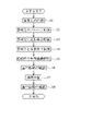
- 4 is a flow chart of a procedure using a medical device;
- FIG. 6 is a diagram showing the state of S2 in FIG. 5, where (a) is an enlarged view of the vicinity of the balloon showing the cross section of the interatrial septum, and (b) is a cross-sectional view of the interatrial septum showing the shape of the puncture hole. .
- FIG. 6 is a diagram showing the state of S3 in FIG. 5, in which (a) is a cross-sectional view of the interatrial septum and an enlarged view of the vicinity of the expansion body showing the inside of the storage sheath in a see-through manner, and (b) is an enlarged view of the expansion body stored in the puncture hole.
- FIG. 3 is a cross-sectional view of the interatrial septum with a sheath inserted;
- FIG. 6 is a diagram showing the state of S4 in FIG. 5, and is an enlarged view of the vicinity of the expansion body showing a cross section of the interatrial septum.
- FIG. 6 is a diagram showing the state of S4 in FIG.
- FIG. 10 is a front view showing the internal structure of the hand control unit, in which (a) shows the state before the towing operation, (b) shows the state in which the cushioning portion is greatly compressed by the towing operation, and (c) shows the towing operation.
- FIG. 10 is a diagram showing a state in which the cushioning portion is compressed to a small size;
- FIG. 11 is a front view showing the internal structure of a handheld operation unit according to a first modified example;
- FIG. 10 is a front view showing the internal structure of the handheld operating portion according to the first modified example, showing a state after a pulling operation;
- FIG. 10 is a front view showing the internal structure of a handheld operating portion according to a second modification, and an enlarged cross-sectional view of the vicinity of the tip of the shaft portion;
- FIG. 11 is a front view showing the internal structure of a handheld operation unit according to a third modified example;
- distal end or distal end side
- proximal end or proximal end side
- the medical device in the following embodiments expands a puncture hole Hh formed in the interatrial septum HA of the patient's heart H, and further performs maintenance treatment to maintain the expanded puncture hole Hh at that size. is configured to
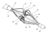
- the medical device 10 of this embodiment includes an elongated shaft portion 20 , an extension body 21 provided at the distal end portion of the shaft portion 20 , and a hand operation device provided at the proximal end portion of the shaft portion 20 . and a portion 23 .
- the extension body 21 is provided with an electrode section 22 which is an energy transmission element for performing the maintenance treatment described above.
- the shaft portion 20 has a distal end portion 30 including a proximal end fixing portion 31 to which the proximal end of the expansion body 21 is fixed, and a distal end fixing portion 33 to which the distal end of the expansion body 21 is fixed.
- the shaft portion 20 has a storage sheath 25 provided on the outermost periphery.
- the expansion body 21 is axially movable forward and backward with respect to the storage sheath 25 .
- the storage sheath 25 can store the expandable body 21 in the interior thereof while being moved to the distal end side of the shaft portion 20 . By moving the storage sheath 25 toward the proximal end from the state in which the expandable body 21 is stored, the expandable body 21 can be exposed.
- the shaft portion 20 has an outer tube 27 extending from the hand operation portion 23 to the base end fixing portion 31 and a traction shaft 26 housed inside the outer tube 27 .
- the traction shaft 26 extends from the proximal end of the shaft portion 20 to the distal end member 35 inside the outer tube 27 , and the distal end is fixed to the distal end member 35 .
- the distal end member 35 to which the distal end portion of the traction shaft 26 is fixed may not be fixed to the expansion body 21. This allows the tip member 35 to pull the expansion body 21 in the compression direction. Further, when the expandable body 21 is stored in the storage sheath 25, by separating the distal end member 35 from the expandable body 21 toward the distal end side, the expandable body 21 can be easily moved in the extending direction, thereby improving the storing performance. can.
- the hand operation unit 23 has a housing 40 gripped by the operator and a traction operation unit 41 operable by the operator.
- the housing 40 includes a slit portion 60 through which the traction operation portion 41 is slidably inserted, an outer tube insertion opening 61 through which the outer tube 27 is inserted, and a traction shaft insertion portion through which the traction shaft 26 is inserted. and an opening 62 .
- the outer tube 27 inserted through the outer tube insertion opening 61 is fixed to an outer tube holding portion 42 provided inside the housing 40 .
- the traction shaft 26 extends from the outer tube holding portion 42 to the proximal side and is led out from the proximal end of the housing 40 in the proximal direction.
- the traction operation section 41 has a slide section 65 slidably held within the housing 40 .
- a buffer portion 43 is provided between the traction operation portion 41 and the traction shaft 26 .
- the buffer portion 43 is formed of a coil spring that is elastically deformable along the length direction.
- a distal end portion 43 a of the buffer portion 43 is fixed to a traction operation portion side fixing portion 66 formed by extending the traction operation portion 41 into the housing 40 .
- a base end portion 43 b of the buffer portion 43 is fixed to the traction shaft side fixing portion 67 of the traction shaft 26 . Since the traction operation part 41 slides toward the base end side from the state shown in FIG. , can be elastically deformed in the direction of compression.
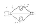
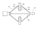
- the expansion body 21 has a plurality of wire portions 50 in the circumferential direction.
- four wire portions 50 are provided in the circumferential direction.
- the wire portions 50 can be expanded and contracted in the radial direction.
- a proximal end portion of the wire portion 50 extends from the proximal end fixing portion 31 toward the distal end side.
- a distal end portion of the wire portion 50 extends from a proximal end portion of the distal end fixing portion 33 toward the proximal end side.
- the wire portion 50 is inclined so as to increase in the radial direction from both ends in the axial direction toward the central portion.
- the wire portion 50 has a concave portion 51 that is recessed radially inward of the expansion member 21 at the center portion in the axial direction.
- the radially innermost portion of the recess 51 is a bottom portion 51a.
- the concave portion 51 defines a receiving space 51b capable of receiving a living tissue when the expansion body 21 is expanded.
- the electrode portion 22 is arranged in the concave portion 51 so as to face the receiving space 51b.
- the wire part 50 forming the expansion body 21 has, for example, a flat plate shape cut out from a cylinder.
- the wire material forming the extension body 21 can have a thickness of 50 to 500 ⁇ m and a width of 0.3 to 2.0 mm. However, it may have dimensions outside this range.
- the wire portion 50 may have a circular cross-sectional shape or other cross-sectional shape.
- the electrode section 22 is composed of, for example, a bipolar electrode that receives electrical energy from an energy supply device (not shown), which is an external device. In this case, electricity is supplied between the electrode portions 22 arranged on each wire portion 50 .
- the electrode part 22 and the energy supply device are connected by a lead wire (not shown) covered with an insulating covering material.
- the conducting wire is led out to the outside through the shaft portion 20 and the handheld operation portion 23 and connected to the energy supply device.
- the electrode section 22 may also be configured as a monopolar electrode. In this case, electricity is supplied between the electrode and the counter electrode prepared outside the body. Further, instead of the electrode portion 22, a heating element (electrode tip) that generates heat by receiving high-frequency electrical energy from an energy supply device may be used. In this case, electricity is supplied between the heating elements arranged in each wire portion 50 . Further, the electrode part 22 may be heated or cooled by microwave energy, ultrasonic energy, coherent light such as laser, heated fluid, cooled fluid, chemical medium, or may generate frictional heat. It can be composed of an energy transfer element capable of imparting energy to the puncture hole Hh, such as a heater having an electric wire or the like, and the specific form is not particularly limited.
- the wire portion 50 can be made of a metal material.
- the metal material for example, titanium-based (Ti--Ni, Ti--Pd, Ti--Nb--Sn, etc.) alloys, copper-based alloys, stainless steels, ⁇ -titanium steels, and Co--Cr alloys can be used. .
- an alloy having spring properties such as a nickel-titanium alloy.
- the material of the wire portion 50 is not limited to these, and may be formed of other materials.
- the shaft portion 20 is preferably made of a material having some degree of flexibility.
- materials include polyolefins such as polyethylene, polypropylene, polybutene, ethylene-propylene copolymers, ethylene-vinyl acetate copolymers, ionomers, or mixtures of two or more thereof, soft polyvinyl chloride resins, Polyamide, polyamide elastomer, polyester, polyester elastomer, polyurethane, fluororesin such as polytetrafluoroethylene, polyimide, PEEK, silicone rubber, latex rubber and the like.
- the traction shaft 26 can be made of, for example, a long wire material such as a nickel-titanium alloy, a copper-zinc alloy or other superelastic alloy, a metal material such as stainless steel, or a relatively rigid resin material.
- the tip member 35 is made of, for example, nickel-titanium alloy, copper-zinc alloy or other superelastic alloy, stainless steel or other metal material, polyolefin, polyvinyl chloride, polyamide, polyamide elastomer, polyurethane, polyurethane elastomer, polyimide, fluororesin, or the like. or a mixture thereof, or a multi-layer tube made of two or more kinds of polymeric materials.
- the treatment method of this embodiment is performed on a patient suffering from heart failure (left heart failure). More specifically, as shown in FIG. 4, for a patient suffering from chronic heart failure in which the myocardium in the left ventricle of the heart H is hypertrophied and the stiffness (hardness) is increased, the blood pressure in the left atrium HLa is increased. It is the method of treatment that is performed.
- a puncture hole Hh is created in the interatrial septum HA (S1).
- the operator delivers the introducer 210 in which the guiding sheath and the dilator are combined to the vicinity of the interatrial septum HA.
- the introducer 210 can be delivered to the right atrium HRa, for example, via the inferior vena cava Iv.
- delivery of the introducer can be done using a guidewire 11 .
- the operator can pass the guidewire 11 through the dilator and deliver the introducer along the guidewire 11 .
- the insertion of the introducer into the living body, the insertion of the guide wire 11, and the like can be performed by a known method such as using an introducer for blood vessel introduction.
- the operator penetrates the puncture device (not shown) from the right atrium HRa side toward the left atrium HLa side to form a puncture hole Hh.
- a puncture device is passed through the dilator and delivered to the atrial septum HA.
- a balloon catheter 100 has a balloon 102 at the tip of a shaft portion 101 .
- the balloon 102 is placed in the interatrial septum HA, it is radially expanded as shown in FIG. 6(a) to widen the puncture hole Hh (S2).
- the puncture hole Hh expands to the same diameter as the expanded balloon 102 in the direction along the fibers, but is difficult to expand in other directions. It has an elongated shape as shown in (b).
- the medical device 10 is delivered to the vicinity of the interatrial septum HA, and the expansion body 21 is arranged at the puncture hole Hh (S3).
- a guidewire is not used during delivery of the medical device 10, but a guidewire may be used for stable operation under pulsation.
- the distal end of the medical device 10 penetrates the interatrial septum HA and reaches the left atrium HLa.
- the expansion body 21 is in a state of being housed in the housing sheath 25 when the medical device 10 is inserted.
- the puncture hole Hh is expanded by the balloon 102, so that the storage sheath 25 can be inserted through the puncture hole Hh.
- the expansion body 21 is exposed by moving the housing sheath 25 to the proximal end side.
- the expansion body 21 is expanded in diameter, and the concave portion 51 is arranged in the puncture hole Hh of the interatrial septum HA to receive the living tissue surrounding the puncture hole Hh in the receiving space 51b (S4).
- the puncture hole Hh is expanded to have a substantially uniform diameter along the circumferential direction.
- the expansion body 21 changes the shape of the puncture hole Hh, but does not expand the maximum diameter. Therefore, the maximum diameter of the puncture hole Hh is equivalent to the longitudinal diameter of the puncture hole Hh expanded by the balloon 102 in S2.
- the operator operates the hand operation unit 23 to move the traction shaft 26 to the proximal end side.
- the expandable body 21 is axially compressed by being pulled in the compression direction by the tip member 35, and the interatrial septum HA is divided into the proximal side upright portion 52 and the distal side upright portion 53. It is gripped and the electrode section 22 is pressed against the living tissue (S5).
- the traction operation part 41 is positioned at the tip of the slit part 60 before being operated.
- the operator slides the traction operation portion 41 to the proximal end of the slit portion 60, thereby moving the traction shaft 26 toward the proximal end side and moving the buffer portion 43 in the compression direction. elastically deformed.
- the traction shaft 26 starts to move proximally, the traction shaft 26 moves proximally, compressing the extension body 21 in the axial direction and clamping the living tissue.
- the moving distance of the traction shaft 26 until the extension body 21 clamps the living tissue becomes greater. Therefore, as shown in FIG. 11(c), even if the amount of slide movement of the pulling operation portion 41 is the same as in the case of FIG. 11(b), the amount of compression of the buffer portion 43 is small. In this case, the traction shaft 26 moves proximally by a distance L2 shown in FIG. 11(c). When L2 is larger than L1, that is, when the thickness of the living tissue is thin, the traction shaft 26 moves more toward the base end side, and the extension body 21 clamps the living tissue.
- the action of the cushioning section 43 causes the traction shaft 26 to move more toward the proximal side when the biological tissue is thinner than when the biological tissue is thick, thereby stabilizing the biological tissue. can be clamped.
- the cushioning portion 43 is elastically deformed to a greater extent to suppress the movement of the traction shaft 26. Therefore, even if the movement amount of the traction operation portion 41 is constant, the expandable body 21 does not excessively penetrate the body tissue. It is possible to prevent the puncture hole Hh from being pinched with excessive force and physically damaged, or from being excessively expanded to make the puncture hole Hh larger than the target.
- the operator After dilating the puncture hole Hh, the operator confirms the hemodynamics (S6).
- the operator delivers the hemodynamic confirmation device 220 to the right atrium HRa via the inferior vena cava Iv, as shown in FIG.
- a known echo catheter can be used as the hemodynamic confirmation device 220.
- the operator can display the echo image acquired by the hemodynamic confirmation device 220 on a display device such as a display, and confirm the amount of blood passing through the puncture hole Hh based on the display result.
- the operator performs maintenance treatment to maintain the size of the puncture hole Hh (S7).
- high-frequency energy is applied to the edge of the puncture hole Hh through the electrode section 22 to cauterize (heat cauterize) the edge of the puncture hole Hh with the high-frequency energy.
- High-frequency energy is applied by applying a voltage between the electrode portions 22 adjacent in the circumferential direction.
- the puncture hole Hh When the living tissue near the edge of the puncture hole Hh is cauterized through the electrode portion 22, a denatured portion of the living tissue is formed near the edge. Since the living tissue in the denatured portion loses its elasticity, the puncture hole Hh can maintain the shape when it is expanded by the expander 21 .
- the operator confirms the hemodynamics again (S8), and if the amount of blood passing through the puncture hole Hh is the desired amount, the diameter of the expandable body 21 is reduced and stored in the storage sheath 25. , withdraw from the puncture hole Hh. Furthermore, the entire medical device 10 is removed from the body, and the treatment is finished.
- the hand operation unit 70 of the first modification has a traction operation unit 72 in a housing 71 , and the outer tube 27 is fixed to an outer tube holding section 73 inside the housing 71 .
- the traction shaft 26 extending proximally from the outer tube holding portion 73 has a traction shaft side fixing portion 78 at its proximal end, to which the distal end portion 74a of the buffer portion 74 is fixed.
- the traction operation section 72 has a traction operation section-side fixing section 77 extending into the housing 71, to which the base end section 74b of the buffer section 74 is fixed.
- the proximal end of the traction shaft 26 may be extended from the traction shaft side fixing portion 78 and led out from the proximal end of the housing 40 in the proximal direction. good. Even in this case, the traction shaft side fixing portion 78 is provided at the proximal end portion of the traction shaft 26 when viewed from the entirety of the traction shaft 26 .
- the pulling shaft 26 moves to the proximal side and the cushioning portion 74 elastically deforms in the extension direction.
- the cushioning portion 74 is elastically deformed more in the extension direction. can do.
- the base end of the traction shaft 26 extends at least to the traction operation section-side fixing portion 77 of the traction operation section 72 and is fixed, and part or the entirety of the traction shaft 26 is elastically deformable along the axial direction. It may be a buffer portion.
- the hand operation unit 80 of the second modification has a traction operation unit 82 in a housing 81 , and the outer tube 27 is fixed to an outer tube holding section 83 inside the housing 81 .
- An intermediate shaft 85 is pulled out from the outer tube 27 to the proximal end side.
- the intermediate shaft 85 extends to the vicinity of the distal end portion 30 of the shaft portion 20 and has a traction operation portion side fixing portion 87 at the distal end.
- a distal end portion 84 a of a buffer portion 84 arranged inside the shaft portion 20 is fixed to the traction operation portion side fixing portion 87 .
- the traction shaft 26 has, at its proximal end, a traction shaft side fixing portion 88 that fixes the proximal end portion 84b of the buffer portion 84, and extends from the traction shaft side fixing portion 88 to the distal side.
- the intermediate shaft 85 moves to the proximal end side, and the cushioning portion 84 arranged in the shaft portion 20 is elastically deformed in the compression direction, thereby extending the traction shaft. 26 moves proximally.
- the cushioning portion 84 is elastically deformed more in the compression direction. can be clamped.
- the buffer portion 84 may be located within the shaft portion 20 .
- the handheld operation unit 90 of the third modified example has a traction operation unit 92 on a housing 91 .
- the buffers 94 are not coaxially arranged with the traction shaft 26 but are arranged in parallel at radially different positions.
- the traction operation part 92 has a traction operation part side fixing part 96 that fixes the distal end part 94a of the buffer part 94, and the traction shaft 26 has a traction shaft side fixing part 97 that fixes the base end part 94b of the buffer part 94. is doing.
- the shock absorber In order to dispose the shock absorber coaxially with the traction shaft 26, it is necessary to insert the entire traction shaft 26 through the shock absorber and then fix the shock absorber and the traction shaft 26 together.
- the cushioning portion 94 in parallel with the pulling shaft 26 at a different position in the radial direction like the hand operation portion 90 of the third modification, the pulling shaft side can be pulled from the side of the pulling shaft 26 . Since it is only necessary to attach the fixing portion 97 and fix the cushioning portion 94 to the traction shaft side fixing portion 97, assembly can be facilitated.
- a plurality of buffer portions 94 may be provided in parallel.
- the medical device 10 has an elongated body 21 that can be radially expanded and contracted, and a distal end portion 30 that includes a proximal end fixing portion 31 to which the proximal end of the expandable body 21 is fixed. and a hand operation portion 23 provided on the proximal end side of the shaft portion 20.
- the shaft portion 20 has a traction shaft 26 that axially compresses the expansion body 21 by moving in the axial direction.
- the hand operation portion 23 has a traction operation portion 41 for axially moving the traction shaft 26, and the traction shaft 26 and the traction operation portion 41 are elastically deformable along the axial direction of the traction shaft 26.
- the expansion body 21 is pulled. Since the cushioning portion 43 is elastically deformed according to the thickness and hardness of the living tissue with which it is in contact, it is possible to keep the pulling force on the expandable body 21 constant regardless of the condition of the living tissue. Therefore, the living tissue can be stably grasped and expanded by the expander 21 .
- the cushioning portion 43 has a distal end portion 43a and a proximal end portion 43b opposite to the distal end portion 43a.
- the pulling shaft 26 has a pulling shaft side fixing portion 67 fixed to the other of the distal end portion 43a and the proximal end portion 43b of the buffer portion 43, and the pulling operation
- the section side fixing portion 66 and the traction shaft side fixing portion 67 may be arranged along the axial direction of the traction shaft 26 . As a result, the traction operation portion 41, the buffer portion 43, and the traction shaft 26 can be housed compactly.
- the traction operation unit side fixing portion 66 is fixed to the distal end portion 43 a of the buffer portion 43
- the traction shaft side fixing portion 67 is fixed to the proximal end portion 43 b of the buffer portion 43
- the traction operation portion 41 is fixed to the shaft of the traction shaft 26 .
- the cushioning portion 43 may be elastically deformed in the compression direction by moving from the distal end side to the proximal end side along the direction. As a result, it is possible to keep the pulling force on the expandable body 21 constant with a simple structure in which the cushioning portion 43 is elastically deformed in the compression direction.
- the buffer part 43 may be a coil spring that allows the pulling shaft 26 to pass through. Thereby, the traction shaft 26 and the buffer portion 43 can be coaxially arranged, and the structure inside the hand operation portion 23 can be made compact.
- the cushioning portion 94 may be one or more coil springs arranged in parallel with the traction shaft 26 . As a result, the cushioning portion 94 can be attached from the side of the traction shaft 26, thereby facilitating assembly.
- the traction operation unit side fixing portion 77 is fixed to the base end portion 74 b of the buffer portion 74
- the traction shaft side fixing portion 78 is fixed to the distal end portion 74 a of the buffer portion 74
- the traction operation portion 72 is fixed to the shaft of the traction shaft 26 .
- a part or the whole of the traction shaft 26 may be elastically deformable along the axial direction of the traction shaft 26 . Thereby, the structure can be made simpler by using the traction shaft 26 itself as a buffer.
- the buffer part 43 may be arranged inside the hand operation part 23 . Thereby, the structure of the shaft portion 20 can be prevented from being complicated.
- the cushioning portion 43 is a coil spring, but the cushioning portion may be any material as long as it can be elastically deformed along the axial direction of the shaft portion 20, and may be made of rubber, a resin material, a bellows-shaped member, or the like. good.
Landscapes
- Health & Medical Sciences (AREA)
- Life Sciences & Earth Sciences (AREA)
- Surgery (AREA)
- Engineering & Computer Science (AREA)
- Plasma & Fusion (AREA)
- Medical Informatics (AREA)
- Otolaryngology (AREA)
- Physics & Mathematics (AREA)
- Cardiology (AREA)
- Biomedical Technology (AREA)
- Heart & Thoracic Surgery (AREA)
- Nuclear Medicine, Radiotherapy & Molecular Imaging (AREA)
- Molecular Biology (AREA)
- Animal Behavior & Ethology (AREA)
- General Health & Medical Sciences (AREA)
- Public Health (AREA)
- Veterinary Medicine (AREA)
- Surgical Instruments (AREA)
Abstract
Description
11 ガイドワイヤ
20 シャフト部
21 拡張体
22 電極部
23 手元操作部
25 収納シース
26 牽引シャフト
27 外管
30 先端部
31 基端固定部
33 先端固定部
35 先端部材
40 筐体
41 牽引操作部
42 外管保持部
43 緩衝部
43a 先端部
43b 基端部
50 線材部
51 凹部
51a 底部
51b 受容空間
52 基端側起立部
53 先端側起立部
55 外縁部
56 背当て部
56a 受け面
57 腕部
57a 屈曲部
60 スリット部
61 外管挿通開口部
62 牽引シャフト挿通開口部
65 スライド部
66 牽引操作部側固定部
67 牽引シャフト側固定部 REFERENCE SIGNS
Claims (8)
- 径方向に拡縮可能な拡張体と、
前記拡張体の基端が固定された基端固定部を含む先端部を有する長尺なシャフト部と、
前記シャフト部の基端側に設けられる手元操作部と、
を備え、
前記シャフト部は、軸方向の移動により前記拡張体を軸方向に圧縮させる牽引シャフトを有し、
前記手元操作部は、前記牽引シャフトを軸方向に移動させる牽引操作部を有し、
前記牽引シャフトと前記牽引操作部は、前記牽引シャフトの軸方向に沿って弾性変形可能な緩衝部を介して連結されている医療デバイス。 a radially expandable expandable body;
an elongated shaft portion having a distal portion including a proximal fixing portion to which the proximal end of the expander is fixed;
a hand operation portion provided on the proximal end side of the shaft portion;
with
the shaft portion has a traction shaft that axially compresses the expander upon axial movement;
The hand operation unit has a traction operation unit that axially moves the traction shaft,
The medical device, wherein the traction shaft and the traction operation section are connected via a cushioning section that is elastically deformable along the axial direction of the traction shaft. - 前記緩衝部は、先端部と、前記先端部と反対側の基端部とを有し、
前記牽引操作部は、前記緩衝部の前記先端部と前記基端部のうちの一方に固定される牽引操作部側固定部を有し、
前記牽引シャフトは、前記緩衝部の前記先端部と前記基端部のうちの他方に固定される牽引シャフト側固定部を有し、
前記牽引操作部側固定部と前記牽引シャフト側固定部は、前記牽引シャフトの前記軸方向に沿って配置される請求項1に記載の医療デバイス。 The buffer portion has a distal end portion and a proximal end portion opposite to the distal end portion,
The traction operation part has a traction operation part-side fixing part fixed to one of the distal end part and the proximal end part of the buffer part,
The traction shaft has a traction shaft side fixing portion fixed to the other of the distal end portion and the proximal end portion of the buffer portion,
The medical device according to claim 1, wherein the traction operation unit side fixing portion and the traction shaft side fixing portion are arranged along the axial direction of the traction shaft. - 前記牽引操作部側固定部は、前記緩衝部の前記先端部に固定され、
前記牽引シャフト側固定部は、前記緩衝部の前記基端部に固定され、
前記牽引操作部を前記牽引シャフトの前記軸方向に沿って先端側から基端側に移動させることで、前記緩衝部が圧縮方向に弾性変形する請求項2に記載の医療デバイス。 The traction operation section side fixing section is fixed to the tip section of the buffer section,
The traction shaft side fixing portion is fixed to the base end portion of the buffer portion,
3. The medical device according to claim 2, wherein the cushioning section is elastically deformed in the compression direction by moving the traction operation section from the distal side to the proximal side along the axial direction of the traction shaft. - 前記緩衝部は、前記牽引シャフトを内側に挿通できるコイルバネである請求項3に記載の医療デバイス。 The medical device according to claim 3, wherein the buffer portion is a coil spring that allows the traction shaft to be inserted inside.
- 前記緩衝部は、前記牽引シャフトと並行して配置される1本または複数本のコイルバネである請求項3に記載の医療デバイス。 The medical device according to claim 3, wherein the buffer is one or more coil springs arranged in parallel with the traction shaft.
- 前記牽引操作部側固定部は、前記緩衝部の前記基端部に固定され、
前記牽引シャフト側固定部は、前記緩衝部の前記先端部に固定され、
前記牽引操作部を前記牽引シャフトの前記軸方向に沿って先端側から基端側に移動させることで、前記緩衝部が伸長方向に弾性変形する請求項2に記載の医療デバイス。 The traction operation section side fixing section is fixed to the base end section of the buffer section,
The traction shaft side fixing portion is fixed to the tip portion of the buffer portion,
3. The medical device according to claim 2, wherein the cushioning section is elastically deformed in the extension direction by moving the traction operation section from the distal side to the proximal side along the axial direction of the traction shaft. - 前記牽引シャフトの一部または全体が、前記牽引シャフトの前記軸方向に沿って弾性変形可能である請求項6に記載の医療デバイス。 The medical device according to claim 6, wherein part or all of the traction shaft is elastically deformable along the axial direction of the traction shaft.
- 前記緩衝部は前記手元操作部内に配置される請求項1~6のいずれか1項に記載の医療デバイス。 The medical device according to any one of Claims 1 to 6, wherein the buffer section is arranged within the handheld operation section.
Priority Applications (3)
| Application Number | Priority Date | Filing Date | Title |
|---|---|---|---|
| JP2023505507A JPWO2022191076A1 (en) | 2021-03-08 | 2022-03-04 | |
| EP22767033.8A EP4309605A1 (en) | 2021-03-08 | 2022-03-04 | Medical device |
| US18/461,982 US20230404665A1 (en) | 2021-03-08 | 2023-09-06 | Medical device |
Applications Claiming Priority (2)
| Application Number | Priority Date | Filing Date | Title |
|---|---|---|---|
| JP2021-036374 | 2021-03-08 | ||
| JP2021036374 | 2021-03-08 |
Related Child Applications (1)
| Application Number | Title | Priority Date | Filing Date |
|---|---|---|---|
| US18/461,982 Continuation US20230404665A1 (en) | 2021-03-08 | 2023-09-06 | Medical device |
Publications (1)
| Publication Number | Publication Date |
|---|---|
| WO2022191076A1 true WO2022191076A1 (en) | 2022-09-15 |
Family
ID=83227931
Family Applications (1)
| Application Number | Title | Priority Date | Filing Date |
|---|---|---|---|
| PCT/JP2022/009469 WO2022191076A1 (en) | 2021-03-08 | 2022-03-04 | Medical device |
Country Status (4)
| Country | Link |
|---|---|
| US (1) | US20230404665A1 (en) |
| EP (1) | EP4309605A1 (en) |
| JP (1) | JPWO2022191076A1 (en) |
| WO (1) | WO2022191076A1 (en) |
Families Citing this family (1)
| Publication number | Priority date | Publication date | Assignee | Title |
|---|---|---|---|---|
| CN117462188B (en) * | 2023-12-28 | 2024-03-29 | 杭州德晋医疗科技有限公司 | Interventional medical instrument |
Citations (5)
| Publication number | Priority date | Publication date | Assignee | Title |
|---|---|---|---|---|
| WO2019138321A1 (en) * | 2018-01-12 | 2019-07-18 | Biosense Webster (Israel) Ltd. | Balloon catheter assisted by pulling a puller-wire |
| WO2019188916A1 (en) * | 2018-03-29 | 2019-10-03 | テルモ株式会社 | Medical device and treatment method |
| WO2020094087A1 (en) | 2018-11-09 | 2020-05-14 | 杭州诺生医疗科技有限公司 | Atrial septostomy device with improved ablation method and atrial septostomy system |
| JP2021036374A (en) | 2019-08-30 | 2021-03-04 | 株式会社Jvcケンウッド | Vehicle monitoring device, vehicle monitoring method, and vehicle monitoring program |
| CN112716557A (en) * | 2021-01-15 | 2021-04-30 | 陶凉 | Intervene left auricle ligator and have its ligature system |
-
2022
- 2022-03-04 JP JP2023505507A patent/JPWO2022191076A1/ja active Pending
- 2022-03-04 WO PCT/JP2022/009469 patent/WO2022191076A1/en active Application Filing
- 2022-03-04 EP EP22767033.8A patent/EP4309605A1/en active Pending
-
2023
- 2023-09-06 US US18/461,982 patent/US20230404665A1/en active Pending
Patent Citations (5)
| Publication number | Priority date | Publication date | Assignee | Title |
|---|---|---|---|---|
| WO2019138321A1 (en) * | 2018-01-12 | 2019-07-18 | Biosense Webster (Israel) Ltd. | Balloon catheter assisted by pulling a puller-wire |
| WO2019188916A1 (en) * | 2018-03-29 | 2019-10-03 | テルモ株式会社 | Medical device and treatment method |
| WO2020094087A1 (en) | 2018-11-09 | 2020-05-14 | 杭州诺生医疗科技有限公司 | Atrial septostomy device with improved ablation method and atrial septostomy system |
| JP2021036374A (en) | 2019-08-30 | 2021-03-04 | 株式会社Jvcケンウッド | Vehicle monitoring device, vehicle monitoring method, and vehicle monitoring program |
| CN112716557A (en) * | 2021-01-15 | 2021-04-30 | 陶凉 | Intervene left auricle ligator and have its ligature system |
Also Published As
| Publication number | Publication date |
|---|---|
| EP4309605A1 (en) | 2024-01-24 |
| JPWO2022191076A1 (en) | 2022-09-15 |
| US20230404665A1 (en) | 2023-12-21 |
Similar Documents
| Publication | Publication Date | Title |
|---|---|---|
| JP7270606B2 (en) | medical device | |
| CN111936061B (en) | Medical device | |
| US7666203B2 (en) | Transseptal puncture apparatus | |
| WO2020026217A1 (en) | Medical device | |
| WO2021065874A1 (en) | Medical device | |
| JPWO2019181612A1 (en) | Medical device | |
| JP7270605B2 (en) | medical device | |
| WO2019181634A1 (en) | Medical device | |
| WO2021065873A1 (en) | Medical device | |
| WO2021065912A1 (en) | Medical device | |
| EP4042960A1 (en) | Medical device | |
| US20230404665A1 (en) | Medical device | |
| JP2022143033A (en) | Medical device and application method thereof | |
| WO2022071169A1 (en) | Medical device system and electrode contact detection method | |
| WO2022071168A1 (en) | Medical device and shunt formation method | |
| WO2022191075A1 (en) | Medical device | |
| WO2023281887A1 (en) | Medical device and method for forming shunt | |
| WO2023281888A1 (en) | Medical device | |
| JP2022136661A (en) | medical device | |
| WO2023282335A1 (en) | Medical device and method for forming shunt | |
| WO2023281878A1 (en) | Medical device and shunt formation method | |
| WO2022071179A1 (en) | Medical device and shunt forming method | |
| EP4205684A1 (en) | Reconfigurable electrode apparatus for diagnosis of arrhythmias | |
| WO2023149496A1 (en) | Medical system and method for using same | |
| JP2022141102A (en) | Medical device and application method thereof |
Legal Events
| Date | Code | Title | Description |
|---|---|---|---|
| 121 | Ep: the epo has been informed by wipo that ep was designated in this application |
Ref document number: 22767033 Country of ref document: EP Kind code of ref document: A1 |
|
| WWE | Wipo information: entry into national phase |
Ref document number: 2023505507 Country of ref document: JP |
|
| WWE | Wipo information: entry into national phase |
Ref document number: 2022767033 Country of ref document: EP |
|
| NENP | Non-entry into the national phase |
Ref country code: DE |
|
| ENP | Entry into the national phase |
Ref document number: 2022767033 Country of ref document: EP Effective date: 20231009 |