WO2023281735A1 - 空気調和システム - Google Patents
空気調和システム Download PDFInfo
- Publication number
- WO2023281735A1 WO2023281735A1 PCT/JP2021/025967 JP2021025967W WO2023281735A1 WO 2023281735 A1 WO2023281735 A1 WO 2023281735A1 JP 2021025967 W JP2021025967 W JP 2021025967W WO 2023281735 A1 WO2023281735 A1 WO 2023281735A1
- Authority
- WO
- WIPO (PCT)
- Prior art keywords
- data
- air conditioning
- period
- storage device
- conditioning system
- Prior art date
- Legal status (The legal status is an assumption and is not a legal conclusion. Google has not performed a legal analysis and makes no representation as to the accuracy of the status listed.)
- Ceased
Links
Images




Classifications
-
- F—MECHANICAL ENGINEERING; LIGHTING; HEATING; WEAPONS; BLASTING
- F24—HEATING; RANGES; VENTILATING
- F24F—AIR-CONDITIONING; AIR-HUMIDIFICATION; VENTILATION; USE OF AIR CURRENTS FOR SCREENING
- F24F11/00—Control or safety arrangements
- F24F11/30—Control or safety arrangements for purposes related to the operation of the system, e.g. for safety or monitoring
- F24F11/32—Responding to malfunctions or emergencies
- F24F11/38—Failure diagnosis
-
- F—MECHANICAL ENGINEERING; LIGHTING; HEATING; WEAPONS; BLASTING
- F24—HEATING; RANGES; VENTILATING
- F24F—AIR-CONDITIONING; AIR-HUMIDIFICATION; VENTILATION; USE OF AIR CURRENTS FOR SCREENING
- F24F11/00—Control or safety arrangements
- F24F11/62—Control or safety arrangements characterised by the type of control or by internal processing, e.g. using fuzzy logic, adaptive control or estimation of values
- F24F11/63—Electronic processing
- F24F11/64—Electronic processing using pre-stored data
-
- F—MECHANICAL ENGINEERING; LIGHTING; HEATING; WEAPONS; BLASTING
- F24—HEATING; RANGES; VENTILATING
- F24F—AIR-CONDITIONING; AIR-HUMIDIFICATION; VENTILATION; USE OF AIR CURRENTS FOR SCREENING
- F24F11/00—Control or safety arrangements
- F24F11/89—Arrangement or mounting of control or safety devices
Definitions
- the present disclosure relates to air conditioning systems.
- Some conventional air conditioning systems have the function of storing various operating data for use in analyzing the cause of an abnormality when it occurs.
- the operating data is data indicating the operating state, and includes data such as pressure and drive current for the compressor, for example.
- Driving data is also called driving information.
- Patent Document 1 operation information held by a control unit when an abnormality occurs is recorded in a memory.
- a configuration is described in which operation information held by the control unit is stored in a memory in a state before the state occurs.
- Patent Document 2 in preparation for the occurrence of an abnormality, operation information of an air conditioner is constantly stored in a memory at regular intervals, and new operation information is overwritten in a storage area storing the oldest operation information. Arrangements are described for storing information chronologically over time.
- Patent Document 1 there are cases where the abnormal state cannot be reproduced based on the operational information at the time of the abnormal occurrence, so in that case, the situation is such that the operational information before the abnormal state cannot be obtained. could arise.
- Patent Document 2 since long-term data including operation information in a non-abnormal state is always stored in the memory, a large amount of unnecessary data is accumulated for analysis of the cause of occurrence when an abnormality occurs. There is a problem that the capacity required for the memory becomes excessive.
- the air conditioning system of the present disclosure solves the above problems, reliably acquires operating data that is a sign of an abnormal state in a state before the occurrence of an abnormal state, and suppresses the amount of acquired operating data. It aims to be able to
- the air conditioning system of the present disclosure includes a sensor that detects data indicating the operating state of air conditioning operation, a control device that controls air conditioning operation, and a storage device.
- the control device temporarily holds the data detected by the sensor, and when the data detected by the sensor satisfies the abnormality determination condition, the data detected by the sensor is stored before the reference period from the time when the data detected by the sensor satisfies the abnormality determination condition. The data temporarily held until the time is stored in the storage device.
- the air conditioning system of the present disclosure it is possible to reliably acquire operational data that is a sign of an abnormal state before an abnormal state occurs, and to suppress the amount of operational data to be acquired.
- FIG. 1 is a diagram showing configurations of a refrigerant circuit and a control circuit of an air-conditioning system 100 according to Embodiment 1.
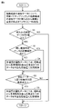
- FIG. 4 is a flowchart showing control for storing operating data of the air conditioning system 100 in the external storage device 7 according to Embodiment 1.
- FIG. 4 is a timing chart showing the timing of storage control of operating data of the air conditioning system 100 according to Embodiment 1.
- FIG. 4 is a diagram showing a specific example of storage control of operating data of the air-conditioning system 100 according to Embodiment 1.
- FIG. 9 is a diagram showing a specific example of storage control of operating data of the air conditioning system 100 according to Embodiment 2; 7 is a flow chart showing control for storing operating data of the air conditioning system 100 in the external storage device 7 according to Embodiment 2.
- FIG. 10 is a flow chart showing control for storing operating data of the air conditioning system 100 in the external storage device 7 according to Embodiment 3.
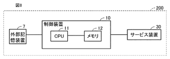
- FIG. 11 is a block diagram showing the configuration of an air conditioning system 200 according to Embodiment 4; 10 is a flow chart showing analysis processing of operation data in the air conditioning system 200 according to Embodiment 4.
- FIG. 1 is a diagram showing configurations of a refrigerant circuit and a control circuit of an air conditioning system 100 according to Embodiment 1. As shown in FIG. FIG. 1 shows states of the refrigerant circuit of the air conditioning system 100 during heating operation and during heating operation.
- the air conditioning system 100 includes a refrigerant circuit including a first heat exchanger 1, a second heat exchanger 2, a compressor 3, a flow control device 4, and a flow switching device 5.
- a refrigerant circuit is a refrigerant path used in the air conditioning system 100 .
- the direction in which the refrigerant flows during cooling is indicated by a solid arrow, and the direction in which the refrigerant flows during heating is indicated by a dashed arrow.
- the direction in which the refrigerant flows during cooling is indicated by a solid line arrow, and the direction in which the refrigerant flows during heating is indicated by a broken line arrow.
- the channel switching device 5 the channel through which the refrigerant flows during cooling is indicated by a solid line, and the channel through which the refrigerant flows during heating is indicated by a broken line.
- the first heat exchanger 1 is an air heat exchanger that exchanges heat between outdoor air and refrigerant.
- the first heat exchanger 1 functions as a refrigerant condenser during cooling operation, and functions as a refrigerant evaporator during heating operation.
- a blower fan for supplying air to the first heat exchanger 1 is provided near the first heat exchanger 1 .
- the blower fan has a function of sucking outdoor air and discharging the air heat-exchanged with the refrigerant by the first heat exchanger 1 to the outdoor.
- the second heat exchanger 2 is a water heat exchanger that exchanges heat between the water in the indoor unit (not shown) and the refrigerant.
- the second heat exchanger 2 functions as a refrigerant evaporator during cooling operation, and functions as a refrigerant condenser during heating operation.
- a compressor 3 that compresses the refrigerant is provided in the refrigerant path between the first heat exchanger 1 and the second heat exchanger 2 .
- the compressor 3 is driven by, for example, an inverter-controlled motor.
- a flow control device 4 is provided in the refrigerant path between the first heat exchanger 1 and the second heat exchanger 2 .
- the flow rate adjusting device 4 has a function of decompressing and expanding the refrigerant, and is configured by, for example, an electronic expansion valve capable of adjusting the flow rate.
- the flow rate adjusting device 4 can adjust the flow rate of the refrigerant in the refrigerant path both during the cooling operation and during the heating operation, and is used to decompress and expand the refrigerant.
- a path on the discharge side of the compressor 3 in the refrigerant path is connected to either the first heat exchanger 1 or the second heat exchanger 2 via the flow path switching device 5 .
- the channel switching device 5 switches the channel through which the refrigerant flows, and is composed of, for example, a four-way valve.
- the flow path switching device 5 switches the refrigerant flow path so that the path on the discharge side of the compressor 3 is connected to the first heat exchanger 1, as indicated by the solid line.
- the flow path switching device 5 switches the flow path of the refrigerant so that the path on the discharge side of the compressor 3 is connected to the second heat exchanger 2 as indicated by the dashed line.
- the control device 10 includes a CPU (Central Processing Unit) 11, a memory 12 (ROM (Read Only Memory) and RAM (Random Access Memory)), and an input/output buffer (not shown) for inputting/outputting various signals. Consists of In the control device 10, various electronic components are mounted on the control board.
- the control board includes, for example, a plurality of input ports used for inputting signals such as detection signals of various sensors, and for controlling various devices such as control signals for the flow rate adjusting device 4, the flow switching device 5, and the compressor 3. and a plurality of output ports for outputting the required signals.
- the CPU 11 expands the program stored in the ROM into the RAM or the like and executes it.
- the program stored in the ROM is a program in which processing procedures of the control device 10 are described.
- the control device 10 controls each device in the air conditioning system 100 according to these programs. This control is not limited to processing by software, and processing by dedicated hardware (electronic circuit) is also possible.
- the external storage device 7 is connected to the control device 10 .
- the external storage device 7 is a storage device for storing and saving operating data, which is data indicating the operating state detected by various sensors, as will be described later.
- memorizing and preserving is a term used to distinguish from temporary memory, and unlike temporary memory that is automatically erased over time, it is necessary to intentionally erase it. It is meant to be remembered for the time being until it occurs.
- the external storage device 7 is composed of a nonvolatile storage device such as flash memory, hard disk drive, or solid state drive. Since the external storage device 7 is a non-volatile storage device, the stored operating data is not erased even when the air conditioning system 100 is powered off.
- the air conditioning system 100 is provided with various sensors that detect operating data, which is data indicating the operating state.
- the following sensors are provided.
- a discharge pressure sensor 21 for detecting the discharge pressure P of the compressor 3 is provided on the discharge side of the compressor 3 .
- the compressor 3 is provided with a current sensor 22 that detects the driving current I of the compressor 3 .
- the compressor 3 is provided with a frequency sensor 23 that detects the frequency F of the compressor 3 .
- the air conditioning system 100 is also provided with the following sensors as sensors for detecting data indicating the operating state.
- a discharge temperature sensor for detecting the temperature of the refrigerant discharged from the compressor 3 (hereinafter referred to as discharge temperature) is provided on the discharge side of the compressor 3 .
- the first heat exchanger 1 is provided with a heat exchanger temperature sensor that detects the temperature of the first heat exchanger 1 .
- the heat exchanger temperature sensor detects the temperature of frost adhering to the first heat exchanger 1 .
- An inlet temperature sensor that detects the temperature of the refrigerant is provided on the inlet side of the second heat exchanger 2 .
- An outlet temperature sensor that detects the temperature of the refrigerant is provided on the outlet side of the second heat exchanger 2 .
- a detection signal of the ejection pressure P detected by the ejection pressure sensor 21, a detection signal of the drive current I detected by the current sensor 22, and a detection signal of the frequency F detected by the frequency sensor 23 are shown as typical examples.
- a detection signal from the sensor is input to the control device 10 .
- the control device 10 gives a control signal to each of the compressor 3, the flow rate adjusting device 4, and the channel switching device 5.
- the control device 10 controls the operating frequency of the compressor 3 based on the control signal.
- the control device 10 controls the opening degree of the flow control device 4 based on the control signal.
- the control device 10 controls switching of the flow path of the flow path switching device 5 based on the control signal.
- the flow path in the flow path switching device 5 is controlled by the control device 10 to become the flow path indicated by the solid line in the figure.
- the opening degree of the flow control device 4 is controlled by the control device 10 based on the degree of superheat.
- the control device 10 opens the flow rate adjusting device 4 so that the suction superheat degree of the compressor 3 obtained from the temperatures detected by the inlet temperature sensor and the outlet temperature sensor of the first heat exchanger 1 becomes a target value. degree and controls the opening degree of the flow rate regulator 4 .
- the high-temperature and high-pressure gas refrigerant compressed by the compressor 3 and discharged passes through the flow path switching device 5 and flows into the first heat exchanger 1 .
- the high-temperature, high-pressure refrigerant that has flowed into the first heat exchanger 1 radiates heat to the outdoor air or the like, and is condensed to become a high-pressure liquid refrigerant.
- the high-pressure liquid refrigerant that has flowed out of the first heat exchanger 1 flows into the flow control device 4, where it is expanded and decompressed to become a low-temperature, low-pressure gas-liquid two-phase refrigerant.
- the gas-liquid two-phase refrigerant that has flowed out of the flow regulating device 4 flows into the second heat exchanger 2 .
- the gas-liquid two-phase refrigerant that has flowed into the second heat exchanger 2 exchanges heat with water and evaporates to become a low-temperature, low-pressure gas refrigerant.
- the gas refrigerant that has flowed out of the second heat exchanger 2 is sucked into the compressor 3 via the flow switching device 5 and compressed again.
- the flow path in the flow path switching device 5 is controlled by the control device 10 to become the flow path indicated by the dashed line.
- the opening degree of the flow control device 4 is controlled by the control device 10 based on the degree of subcooling. Specifically, the controller 10 adjusts the degree of subcooling at the outlet of the second heat exchanger 2, which is obtained from the temperatures detected by the inlet temperature sensor and the outlet temperature sensor of the second heat exchanger 2, to a target value. , determines the opening of the flow control device 4 .
- the high-temperature and high-pressure gas refrigerant compressed by the compressor 3 and discharged passes through the flow path switching device 5 and flows into the second heat exchanger 2 .
- the high-temperature, high-pressure refrigerant that has flowed into the second heat exchanger 2 radiates heat to water, is condensed, and becomes high-pressure liquid refrigerant.
- the high-pressure liquid refrigerant that has flowed out of the second heat exchanger 2 flows into the flow control device 4, where it is expanded and decompressed to become a low-temperature, low-pressure gas-liquid two-phase refrigerant.
- the gas-liquid two-phase refrigerant that has flowed out of the flow control device 4 flows into the first heat exchanger 1 .
- the gas-liquid two-phase refrigerant that has flowed into the first heat exchanger 1 exchanges heat with the outdoor air, evaporates, and becomes a low-temperature, low-pressure gas refrigerant.
- the gas refrigerant that has flowed out of the first heat exchanger 1 is sucked into the compressor 3 via the flow switching device 5 and compressed again.
- FIG. 2 is a flowchart showing control for storing operating data of the air conditioning system 100 in the external storage device 7 according to Embodiment 1.
- FIG. 2 The control shown in FIG. 2 is executed by the CPU 11 of the control device 10 .
- FIG. 2 as an example of storage control of the operating data of the air-conditioning system 100 according to Embodiment 1, a plurality of types of discharge pressure P detected by the discharge pressure sensor 21 and drive current I detected by the current sensor 22 are shown. An example of storage control of operating data when determining an abnormal state based on the operating data will be described.
- the CPU 11 of the control device 10 executes the following processing in the storage control of the driving data.
- step S1 a plurality of types of operating data detected by a plurality of types of sensors for detecting data indicating the operating state described above are sampled at a period C, and the sampled plurality of types of operating data are stored for a period A in the past from the present time. are temporarily stored in a memory 12 in chronological order up to the point of time going back to . As a result, the operating data is temporarily held in the memory 12 .
- period C is set to a period such as a period of one minute.
- control device 10 causes the memory 12 to temporarily retain operational data over a period A (for example, several tens of minutes) in time series during the operation of the air conditioning system 100 .
- temporary storage means that the time-series operation data over the period A is stored in the memory 12 while being constantly updated in a first-in, first-out manner, so that the newly stored data will be stored after a certain period of time (after the period A has elapsed). means to be temporarily stored, such as to be erased. In this manner, in the control device 10, the operating data indicating the operating state of the air conditioning operation is temporarily stored and held in the memory 12 for a certain period of time, the period A, while being constantly updated.
- step S2 it is determined whether any of the plurality of types of operation data detected by the plurality of types of sensors described above is equal to or greater than a threshold set as an abnormal value for each data. . Any of the operating data determined in step S2 does not include the concept of all operating data, but rather the concept of part of the operating data. If it is determined in step S2 that any of the operating data is not equal to or greater than the threshold value, the process returns. On the other hand, if it is determined in step S2 that any of the operating data exceeds the threshold, then in step S3 described later, the operating data exceeding the threshold has already been stored in the external storage device 7 in step S3. It is determined whether there is data saved by
- step S4 If it is determined in step S3 that there is no data already stored and saved in the external storage device 7 corresponding to the operating data exceeding the threshold value, in step S4 all types of operating data are stored from the current time point.
- the data up to the point in time going back by the reference period B is read out from the memory 12, stored in the external storage device 7 and saved, and the process proceeds to step S5.
- both the discharge pressure P and the drive current I are set to the reference value from the present time.
- the data up to the point in time going back by the period B is stored in the external storage device 7 and saved.
- the reference period B is a certain period shorter than the period A, and is a predetermined period expected to enable the cause of the operating data exceeding the threshold to be specified based on the transition of the operating data. is the period As an example, the reference period B is set to a fixed period such as 15 minutes.
- step S4 is not executed. Proceed to S5. As a result, it is possible to prevent redundant operation data from being saved. However, if there is enough capacity, the process of step S4 may be executed to store additional data. For example, in consideration of the possibility that the driving data may repeatedly exceed the threshold or fall below the threshold, data for several times in the past may be left.
- step S5 based on multiple types of operating data detected by multiple types of sensors that detect data indicating the operating state, it is determined whether an abnormality determination condition for certifying that an abnormality has occurred in the air conditioning system 100 has been established. to decide.
- An example of the abnormality determination condition in step S5 is that both the discharge pressure P and the drive current I in the operation data are equal to or greater than threshold values.
- step S5 If it is determined in step S5 that the abnormality determination condition is not satisfied, return. On the other hand, if it is determined in step S5 that the abnormality determination condition is satisfied, in step S6, data of all types of operation data from the current time to the point in time preceding the reference period B is stored from the memory 12. Read out, store and save in the external storage device 7, and return. For example, when the discharge pressure P and the drive current I are used as the operating data, in step S6, data for both the discharge pressure P and the drive current I from the present time to the point in time preceding the reference period B is is stored in the external storage device 7 and saved.
- FIG. 3 is a timing chart showing the timing of storage control of the operating data of the air conditioning system 100 according to Embodiment 1.
- FIG. 3 is a timing chart showing the timing of storage control of the operating data of the air conditioning system 100 according to Embodiment 1.
- the operating data indicating the operating state of the air conditioning operation is temporarily held in the memory 12 for a fixed period of time A, while being constantly updated. Then, when it is determined that any of the operating data is equal to or higher than the threshold value, for all types of operating data, the data from the current point to the point in time preceding the reference period B is read out from the memory 12 and stored in the external memory. It is stored and saved in the storage device 7 .
- the period A during which the operating data is temporarily stored in the memory 12 is longer than the reference period B, for example.
- the length of the period during which the operation data is temporarily stored in the memory 12 may be the same as the length of the reference period.
- the length of the period during which the operation data is temporarily stored in the memory 12 may be equal to or longer than the length of the reference period.
- the length of the period during which the driving data is temporarily stored in the memory 12 is at least the length of the reference period, and may be set longer than the reference period within a range that does not impose a storage capacity of the memory 12 .
- the data from the present time to the point in time preceding the reference period B is read from the memory 12 and stored in the external storage device 7 for all types of operation data. stored and saved in
- FIG. 4 is a diagram showing a specific example of storage control of the operating data of the air conditioning system 100 according to Embodiment 1.
- the abnormality determination condition is established.
- FIG. 4A1 and 4A2 show the relationship between the operating data when the operating data storage control according to Embodiment 1 is executed and the period of the operating data stored and saved in the external storage device 7. It is shown.
- FIG. 4A1 shows the current value of the drive current I over time.
- FIG. 4A2 shows the pressure value of the discharge pressure P over time.
- FIG. 4(B1) and (B2) show, as a comparative example of the storage control of the driving data according to the first embodiment, only when the abnormality determination condition is met, the point in time which is a reference period B before the present point in time.
- 1 shows an example of storage control of operation data in which the data up to and including the above are read out from the memory 12 and stored in the external storage device 7 to be saved.
- FIG. 4B1 shows the current value of the drive current I over time.
- FIG. 4B2 shows the pressure value of the discharge pressure P over time.
- the operating data storage control according to the first embodiment when executed, as will be described below, the operating data that is a sign of an abnormal state is reliably acquired in the state before the abnormality determination condition is established. be able to.
- the external storage device 7 stores and saves the data for both the discharge pressure P and the drive current I from the present time to the time point before the reference period B.
- the abnormality determination condition is established when the driving current I is equal to or higher than the threshold value and the discharge pressure P is equal to or higher than the threshold value.
- both the discharge pressure P and the drive current I are stored from the present time to the point of time preceding the reference period B in the past.
- the data is stored and saved in the external storage device 7 .
- the control device 10 temporarily holds the data detected by the sensor, and when the data detected by the sensor exceeds the threshold, it becomes the threshold.
- the external storage device 7 which is a storage device, the data temporarily held during the period from the time when the reference period was reached to the time before the reference period, the operating data that becomes a sign of the abnormal state in the state before the abnormal state occurs. can be reliably obtained, and the amount of operation data to be obtained can be suppressed.
- the external storage device 7 stores the data of both the discharge pressure P and the drive current I from the present time to the point of time preceding the reference period B in the past. saved as As a result, in the storage control of the operating data in the first embodiment, based on the data before the reference period from the time when any of the operating data becomes equal to or greater than the threshold value, the sign of an abnormal state is detected in the state before the abnormality determination condition is established. It is possible to reliably acquire the driving data that becomes In addition, in the first embodiment, since it is possible to reliably acquire the operating data that is a sign of an abnormal state, the accuracy of identifying the sign of an abnormal state is improved.
- the operating data when the abnormality determination condition is satisfied since it is possible to reliably acquire the operating data that is a sign of an abnormal state, when the abnormality determination condition is satisfied, the operating data when the abnormality determination condition is satisfied and the operation data indicating the abnormal state are obtained.
- the fundamental cause of the abnormal state By analyzing the operating state together with the predictive operating data, the fundamental cause of the abnormal state can be easily analyzed.
- the first embodiment since it is possible to reliably acquire the operating data that is a sign of an abnormal state, when it is confirmed that a sign of an abnormal state has occurred, information on the occurrence of a sign of an abnormal state is provided as a service. By contacting maintenance personnel such as engineers by various communication methods such as e-mail, it is possible to analyze the operating state before the abnormality determination condition is established.
- the first embodiment since it is possible to reliably acquire the operating data that is a sign of an abnormal state, various operation adjustment measures for improving the operating state can be performed before the abnormality determination condition is satisfied. In addition, parts can be replaced to improve operating conditions, and adverse effects on the user of the air conditioning system 100 can be suppressed.
- Embodiment 2 in the storage control of the operation data of the air conditioning system 100, the reference period such as the reference period B described in Embodiment 1 is set as a level that has not reached the threshold level described above. An example of setting the period required to reach the threshold level from the reference value will be described.
- FIG. 5 is a diagram showing a specific example of storage control of the operating data of the air conditioning system 100 according to the second embodiment.
- the reference period D used when the driving current I reaches the threshold value after passing through the reference value among the operation data will be described.
- the reference value is set, for example, to the maximum value to which each operating data can change in the normal operating state in which the air conditioning system 100 is in a normal operating state.
- the operating data reaches the threshold level after exceeding the reference value level.
- it is considered important to store the driving data when it reaches the level of such a reference value and use it for analysis.
- the period required for reaching the threshold level from the reference value level may differ, even for the same type of driving data, depending on the driving situation and the abnormal situation. For example, as shown in FIG. 5, when the operating data exceeds a threshold value, the external storage device 7 stores the data up to a point in time preceding the threshold value by a relatively short constant reference period H. If the change speed of the operation data is relatively slow, the operation data may not be obtained when the operation data reaches the level of the reference value, as shown in area b.
- the reference period that changes according to the change speed of the operating data D is used to store and save the operating data in the external storage device 7 .
- the operation data in order to reliably store and save the operation data in the external storage device 7 when the operation data reaches the level of the reference value, the operation data reaches the level of the reference value.
- the control device 10 determines the point in time. Then, when the operating data reaches the threshold level, the control device 10 sets a reference period D as a period from when the operating data reaches the threshold level to when it reaches the reference value level. Then, the control device 10 causes the external storage device 7 to store and save the data from the time when the level of the threshold is reached to the time before the reference period D.
- the control device 10 can reliably store the data in the external storage device 7 .
- FIG. 6 is a flow chart showing control for storing the operating data of the air conditioning system 100 in the external storage device 7 according to Embodiment 2.
- FIG. The control shown in FIG. 6 is executed by the CPU 11 of the control device 10 .
- FIG. 6 as an example of storage control of the operating data of the air-conditioning system 100 according to Embodiment 1, a plurality of types of discharge pressure P detected by the discharge pressure sensor 21 and drive current I detected by the current sensor 22 are shown. An example of storage control of operating data when determining an abnormal state based on the operating data will be described.
- the CPU 11 of the control device 10 executes the following processing in the storage control of the driving data.
- step S11 similar to step S1 in FIG. 2, the plurality of types of operation data detected by the plurality of types of sensors described above are sampled at period C, and the plurality of types of operation data are sampled for period A in the past from the present time. Temporarily stored in a memory 12 in chronological order up to the point in time going back.
- step S12 it is determined whether or not any of the plurality of types of operation data detected by the plurality of types of sensors has reached the reference value as described with reference to FIG. do.
- step S13 the elapsed time from the point in time when the reference value is reached in step S12 is started, and the process proceeds to step S14.
- step S14 the process proceeds to step S14.
- step S14 similarly to step S2 in FIG. 2, any one of the plurality of types of operation data detected by the plurality of types of sensors described above is equal to or greater than the threshold set as an abnormal value for each data. It is determined whether or not If it is determined in step S14 that any of the operating data does not exceed the threshold value, the process returns. On the other hand, if it is determined in step S14 that any of the operating data exceeds the threshold, in step S15, similar to step S3 in FIG. 7, it is determined whether or not there is data already stored and saved in step S16, which will be described later.
- step S16 If it is determined in step S15 that there is no data already stored and saved in the external storage device 7 corresponding to the operating data exceeding the threshold value, in step S16 all types of operating data are stored from the present time.
- the data in the reference period D going back to the time when the reference value determined in S12 was reached is read out from the memory 12, stored in the external storage device 7 and saved, and the process proceeds to step S17.
- step S16 the data of the elapsed time from which time measurement was started in step S13 is confirmed, the confirmed elapsed time is set as the reference period D, the data in the reference period D is read from the memory 12, and the read data is read out. is stored in the external storage device 7 and saved.
- step S15 is performed to prevent redundant operation data from being saved. Proceed to S17.
- step S17 as in step S5 of FIG. 2, based on multiple types of operating data detected by multiple types of sensors, whether or not an abnormality determination condition has been established to recognize that an abnormal state has occurred in the air conditioning system 100. to judge whether
- step S17 If it is determined in step S17 that the abnormality determination condition is not satisfied, the process returns. On the other hand, if it is determined in step S17 that the abnormality determination condition is established, in step S18, similar to step S6 in FIG. The data up to the point in time is read out from the memory 12, stored in the external storage device 7 and saved, and the process returns.
- the control device 10 stores the operation data in the external storage device 7 using the reference period D that changes according to the change speed of the operation data, as described with reference to FIG. Remember and save.
- the control device 10 stores the operation data in the external storage device 7 using the reference period D that changes according to the change speed of the operation data, as described with reference to FIG. Remember and save.
- the second embodiment it is possible to reliably store and save the operating data in the external storage device 7 when the operating data reaches the level of the reference value.
- Embodiment 3 in the storage control of the operation data of the air conditioning system 100, the change rate of the operation data within a predetermined unit period is used as a reference period such as the reference period B described in the first embodiment. An example of setting a period that changes according to is described.
- the reference period which is the past period for which the data is stored when the threshold is reached, is changed according to the period from the level of the reference value to the level of the threshold for the driving data. I explained an example.
- different reference periods are set depending on whether the change rate of the operating data is less than the change rate judgment value or is equal to or greater than the change rate judgment value. Change the reference time as follows.
- change rate determination in which the rate of change of the operating data is set to exceed the standard rate of change during the period from the level of the reference value described in Embodiment 2 until the level of the threshold value is reached. If it is greater than or equal to the value, the driving data will reach the threshold level in a shorter period of time than the standard period of time. In that case, it is possible to acquire the operating data required for analyzing the abnormal state in a reference period shorter than the standard set reference period.
- the period that changes according to the rate of change of the operating data is defined as the above-described reference period. Storage control of the operating data set as .
- FIG. 7 is a flowchart showing control for storing the operating data of the air conditioning system 100 in the external storage device 7 according to Embodiment 3.
- the control shown in FIG. 7 is executed by the CPU 11 of the control device 10 .
- FIG. 7 as an example of storage control of the operating data of the air-conditioning system 100 according to Embodiment 1, a plurality of types of discharge pressure P detected by the discharge pressure sensor 21 and drive current I detected by the current sensor 22 are shown. An example of storage control of operating data when determining an abnormal state based on the operating data will be described.
- the CPU 11 of the control device 10 executes the following processing in the storage control of the driving data.
- step S21 similar to step S1 in FIG. 2, the plurality of types of operation data detected by the plurality of types of sensors described above are sampled at period C, and the plurality of types of operation data are sampled for period A from the current point in the past. Temporarily stored in a memory 12 in chronological order up to the point in time going back.
- step S22 the rate of change of the operating data is calculated for each of the plurality of types of operating data based on the operating data within a predetermined unit period (for example, one minute).
- step S23 it is determined whether or not the rate of change of any of the operating data whose rate of change has been calculated in step S22 is equal to or greater than the rate of change determination value. For example, in step S23, a change rate higher than the standard change rate of each driving data is set as the change rate determination value. As an example, if the standard rate of change is "R", the rate of change determination value is set to "2 ⁇ R".
- step S23 If it is determined in step S23 that the change rate of any of the operating data is greater than or equal to the change rate judgment value, then in step S23, the sampling period of all the operating data is changed from the standard period C to a shorter period than the period C. Change to G and proceed to step S25. As an example, the period G is set to 1/2 period of the period C. If it is determined in step S23 that the change rate of any of the operating data is not equal to or greater than the change rate determination value, the sampling cycle is not changed from the standard cycle C, and the process proceeds to step S25.
- step S25 similarly to step S2 in FIG. 2, any one of the plurality of types of operation data detected by the plurality of types of sensors described above is equal to or greater than the threshold set as an abnormal value for each data. It is determined whether or not If it is determined in step S25 that any of the operating data does not exceed the threshold value, the process returns. On the other hand, if it is determined in step S25 that any of the operating data is equal to or greater than the threshold, in step S26 similar to step S3 in FIG. 7, it is determined whether or not there is data already stored and saved in step S27.
- step S27 If it is determined in step S26 that there is no data already stored and saved in the external storage device 7 corresponding to the operating data exceeding the threshold value, in step S27 all types of operating data are stored from the current time point. , the data in the reference period E according to the rate of change of the operating data exceeding the threshold is read out from the memory 12 and stored in the external storage device 7, and the process proceeds to step S28.
- the reference period E is used as an example of the reference period E. If the rate of change corresponding to the operating data exceeding the threshold is less than the above-described rate of change determination value, the standard reference period E1 similar to the above-described reference period B is set, and the operating data exceeding the threshold is set. is equal to or greater than the above-described change rate determination value, the reference period E2 is set to 1/2 of the above-described reference period B. As a result, when the rate of change corresponding to the operating data exceeding the threshold value is less than the aforementioned rate of change determination value, the period is as short as 1/2 of the standard reference period E1 similar to the aforementioned reference period B. The operating data for the reference period E2 is stored and saved in the external storage device 7 .
- step S26 determines whether there is data already stored and saved in the external storage device 7 corresponding to the operation data exceeding the threshold. If it is determined in step S26 that there is data already stored and saved in the external storage device 7 corresponding to the operation data exceeding the threshold, step Proceed to S28.
- step S28 as in step S5 of FIG. 2, based on the plurality of types of operating data detected by the plurality of types of sensors described above, whether an abnormality determination condition for certifying that an abnormality has occurred in the air conditioning system 100 has been established. determine whether or not
- step S28 If it is determined in step S28 that the abnormality determination condition is not satisfied, the process returns. On the other hand, if it is determined in step S28 that the abnormality determination condition is established, in step S29, similar to step S6 in FIG. The data up to the point in time is read out from the memory 12, stored in the external storage device 7 and saved, and the process returns.
- the control device 10 stores and saves the operating data in the external storage device 7 using the reference period E that changes according to the change rate of the operating data. Furthermore, the operating data is sampled at a sampling period that varies according to the rate of change of the operating data. As a result, in the third embodiment, it is possible to store and save the operating data required for analyzing the abnormal state in the external storage device 7 during the reference period shorter than the standard set reference period. can. Also, the operation data can be sampled at an appropriate timing according to the length of the period of the operation data to be stored and saved in the external storage device 7 .
- the control device 10 can change the storage time of the operation data and the sampling period of the operation data according to the change rate of the operation data. Therefore, the operating data necessary for analyzing the abnormal state of the air conditioning system 100 can be stored in the external storage device 7 at the required density.
- Embodiment 4 As a fourth embodiment, a service device 30 as an analysis device can be connected to the control device 10 corresponding to each of the above-described embodiments, and when the service device 30 is connected to the control device 10, external storage An air conditioning system 200 that reads data stored in the device 7 and analyzes the operating state of the air conditioning operation based on the data stored in the external storage device 7 will be described.
- FIG. 8 is a block diagram showing the configuration of an air conditioning system 200 according to Embodiment 4. As shown in FIG.
- a service device 30 as an analysis device can be connected to the air conditioning system 100 as described above.
- the service device 30 is a device capable of executing a program for analyzing the cause of occurrence of an abnormal state based on the operating data stored in the external storage device 7 .
- the air conditioning system 200 is a system including a service device 30 in addition to the configuration of the air conditioning system 100 described above.
- the service device 30 may be configured by a computer dedicated to the maintenance of the air conditioning system 200, which includes a processor that executes an analysis program for analyzing the abnormal state of the air conditioning system 200, and such an analysis program as one program. It may be configured by a general-purpose computer that is installed and executes the analysis program.
- the service device 30 is connected to the control device 10 via a converter device at a communication line terminal block provided in the air conditioning system 200 .
- the service device 30 reads the operating data stored in the external storage device 7 as described above by executing the analysis program while connected to the control device 10 .
- the cause of the abnormal state is analyzed.
- FIG. 9 is a flowchart showing analysis processing of operating data in the air conditioning system 200 according to Embodiment 4.
- the refrigerant circuit including the first heat exchanger 1, the second heat exchanger 2, the compressor 3, the flow rate adjusting device 4, and the flow switching device 5 as shown in FIG. are provided, but these descriptions are omitted.
- step S31 the operating data stored in the external storage device 7 is read.
- step S32 the cause of the abnormal state is analyzed based on the operation data read out in step S31, and the process returns.
- step S32 the following processing is executed as an example.
- the detected discharge temperature is stored in the external storage device 7 as operating data before reaching a threshold value for determining the abnormal state of the discharge temperature.
- the air conditioning system 200 was operated with an insufficient amount of refrigerant in the refrigerant circuit.
- the cause of such an abnormal state is analyzed, it is necessary to perform control to increase the amount of refrigerant as coping control.
- the following effects can be obtained. For example, when a maintenance worker such as a service person is dispatched to the site in response to an abnormal state in which an abnormality determination condition is satisfied, operation data within a reference period when the abnormality determination condition is satisfied, and The operating data within the reference period when the operating data reaches the threshold value before the abnormality determination condition is satisfied can be read out from the external storage device 7 to easily analyze the cause of the abnormal state. In particular, by comprehensively analyzing the operating data within the reference period when the abnormality determination condition is satisfied and the operating data within the reference period when the operation data reaches the threshold value before the abnormality determination condition is satisfied , it is possible to further investigate the cause of the occurrence of the abnormal state.
- the operating data within the reference period when the operating data reaches the threshold value before the abnormality determination condition is satisfied is read from the external storage device 7. Accordingly, it is possible to confirm the current operating state of the air conditioning system 200 and to predict an abnormal state that may occur in the air conditioning system 200 in the future.
- the operating data stored in the external storage device 7 can be It may be read from the system 200 via the centralized management controller to the service device 30 or other computers existing outside, and furthermore, the service device 30 or other computers existing externally via the centralized management controller and server may be read out.
- the air conditioning system 200 may attach the operating data to an e-mail and read out the operating data to the outside.
- the transmission of the operating data read from the external storage device 7 by e-mail may be performed at regular timing. Then, by selecting and using an appropriate reading method according to the operating status of the air conditioning system 200 from among various reading methods of the operation data in this manner, quick maintenance services for the air conditioning system 200 can be provided. It can be carried out.
- the destination of the e-mail may be maintenance personnel such as service personnel, or the designer of the air conditioning system 200. .
- the operating data within the reference period when the abnormality determination condition is satisfied, and the operating data within the reference period when the operation data reaches the threshold value before the abnormality determination condition is satisfied may be stored according to the data capacity of the external storage device 7 .
- a plurality of pieces of operation data are detected as the operation data to be stored in the external storage device 7.
- the sampling period of these pieces of operation data may be the same for all the pieces of operation data.
- the period may be different depending on the characteristics of .
- the sampling period may be set to be longer for operation data with a smaller width of data change.
- Operation data within the reference period when the abnormality determination condition to be stored in the external storage device 7 is satisfied, and operation data within the reference period when the operation data reaches the threshold value before the abnormality determination condition is satisfied may be arbitrarily determined according to the characteristics of the main operating data subject to abnormality determination. For example, even if 10 kinds of operation data are sampled as operation data for abnormality determination, if the operation data related to the operation data of the main abnormality target can be narrowed down to 5 kinds, only such related operation data may be selected and stored in the external storage device 7.
- Embodiment 3 an example in which the sampling period is changed has been described. However, if the storage capacity of the external storage device 7 is small, the sampling period may not be changed. In addition, when the operating data already stored in the external storage device 7 reduces the storage capacity of the external storage device 7, the controller controls the subsequent sampling cycle of the operating data to be longer than the specified cycle. 10 may be changed.
- the reference period described in each of the above embodiments is basically determined at the design stage.
- such a reference period is determined by providing a selection device such as a selection switch for selecting the reference period from a plurality of reference periods in the air conditioning systems 100 and 200, and allowing a person such as an administrator of the air conditioning systems 100 and 200 to select the air conditioning period.
- the selection device may be operated according to the installation environment of the harmonization systems 100 and 200 to enable selection.
- the sampling period described is basically determined at the design stage.
- such a sampling period is determined by providing a selection device such as a selection switch for selecting the sampling period from a plurality of sampling periods in the air conditioning system 100, 200, and allowing a person such as an administrator of the air conditioning system 100, 200 to select the air conditioning system.
- the selection device may be operated according to the installation environment of the harmonization systems 100 and 200 to enable selection.
- the reference period which is the period during which the operating data described in each of the above embodiments is stored in the external storage device 7, may be set according to the characteristics of the operating data. For example, for driving data that has the characteristic of reaching the threshold slowly, the reference period is set longer than the standard reference period, and for driving data that has the characteristic of rapidly reaching the threshold, the reference period is set to the standard period. It may be set longer than the reference period.
- the control device 10 and the external storage device 7 may be installed at a remote location away from the locations where the refrigerant circuits of the air conditioning systems 100 and 200 are arranged.
- various devices of the refrigerant circuit to be controlled by the control device 10 may be connected to the control device 10 via a network such as the Internet.
- the control device 10 is installed near the refrigerant circuit
- the external storage device 7 may be installed at a remote location away from the location where the refrigerant circuit is arranged.
- the temporarily stored operation data for period A data whose state does not change over time other than ON or OFF, such as switch input information, may be used.
- the data may be stored only when the input changes, eg, when it switches from ON to OFF. In this way, the required storage capacity can be reduced by excluding data from being stored while the state is maintained without changing from ON or OFF.
- Data such as threshold values for determining an abnormal state and a modified example of a sampling method for operation data will be described.
- the type of abnormal state, data related to the abnormal state, and data related to determination of the abnormal state such as a threshold value corresponding to the abnormal state are stored in the control device 10 in association with each type of abnormal state. good too.
- Data related to determination of such an abnormal state may be stored in the control device 10 in the form of a table for each type of abnormal state. Based on the data stored in this way, the control device 10 may determine whether or not the abnormality determination condition as described above is satisfied.
- the data related to determination of an abnormal state stored in the control device 10 in this manner is derived from, for example, maintenance information including a history of responses to abnormalities that occurred in the past, information possessed by the designer, and the like.
- the sampling method of the operation data as described above it may be stored in the control device 10 in association with the type of abnormal state, and the operation data may be sampled by a sampling method based on the stored data.
- the operation data is stored in the control device 10 in association with the data related to the determination of the abnormal state described above, and the operation data is sampled by a sampling method based on the stored data. may be executed.
- the operation history information and the like of one air conditioning system 100, 200 or a plurality of air conditioning systems 100, 200 are aggregated in the cloud, and based on the aggregated operation history information, a machine learning function using artificial intelligence The accuracy of parameters such as the threshold may be increased.
- the degree to which the data values fluctuate differs depending on the type of operating data. For driving data that fluctuates greatly and may drop below the threshold immediately after exceeding the threshold for a moment, if the threshold is exceeded for a certain period of time (for example, if the threshold is exceeded for X seconds in a row) , the control device 10 may store the operation data.
- Embodiments 1 to 4 data stored in the external storage device 7, that is, operation data that enables analysis of signs of an abnormal state are transmitted to maintenance personnel such as service personnel. , the driving state can be analyzed.
- the maintenance personnel may be contacted at various timings. For example, maintenance personnel may be contacted on a regular basis (eg, every three months) and the data sent to the maintenance personnel's computer. Alternatively, each time preset data such as data that is a sign of an abnormal state is stored in the external storage device 7, the maintenance staff may be contacted and the data may be sent to the maintenance staff's computer. Alternatively, maintenance personnel may be contacted when controller 10 determines that anomalous operational data is present, and the data may be transmitted to the maintenance personnel's computer. In addition to the abnormal operation data, data that is a sign of an abnormal state may also be sent to the maintenance personnel's computer.
- only the main data may be transmitted at the stage of contacting the maintenance personnel, and the maintenance personnel may be able to retrieve other past data from the external storage device 7 when the maintenance personnel arrive at the site.
- the communication and data transmission to the maintenance personnel described above may be automatically executed by the control device 10 or the centralized control controller.
- the control device 10 may store data in the external storage device 7 in response to requests from maintenance personnel who are remote from the air conditioning systems 100 and 200 .
- the control device 10 may add, to the data to be stored in the external storage device 7, the type of operation data requested by the maintenance personnel.
- the control device 10 may change the length of the data storage period in response to a request from maintenance personnel.
- the air conditioning system 100 described above may be configured as one air conditioner.
- the present disclosure relates to air conditioning systems 100 and 200.
- the air conditioning systems 100 and 200 include sensors such as a discharge pressure sensor 21 and a current sensor 22 that detect data indicating the operating state of air conditioning operation, a control device 10 that controls the air conditioning operation, and an external storage device 7 that is a storage device. and
- the control device 10 temporarily holds the data detected by the sensor (step S1 in FIG. 2, step S11 in FIG. 6, step S21 in FIG. 7), and when the data detected by the sensor satisfies the abnormality determination condition, Second, the data temporarily held during the period from the time when the data detected by the sensor satisfies the abnormality determination condition to the time before the reference period is stored in the external storage device 7 which is a storage device. (Steps S2 to S4 in FIG. 2, steps S14 to S16 in FIG. 6, steps S25 to S27 in FIG. 7).
- control device 10 temporarily holds the data detected by the sensor, and when the data detected by the sensor exceeds the threshold, By storing the data temporarily held during the period in the external storage device 7, which is a storage device, the operational data that is a sign of the abnormal state can be reliably acquired in the state before the abnormal state occurs. Data volume of data can be suppressed.
- control device 10 sets a predetermined fixed period as the reference period B (step S4 in FIG. 2).
- control device 10 sets a predetermined fixed period as the reference period B, so that the setting of the reference period can be simplified.
- the control device 10 sets the reference period D as the period required for the data detected by the sensor to reach the threshold level from the reference value set to a level that has not yet reached the threshold level ( Set the reference period D) (step S16 in FIG. 6)
- the control device 10 sets, as the reference period D, the period required for the data detected by the sensor to reach the threshold level from the reference value set to a level that has not yet reached the threshold level. Therefore, the operating data at the point when the operating data reaches the level of the reference value can be reliably stored and saved in the external storage device 7 which is a storage device.
- control device 10 sets, as the reference period E, a period that changes according to the change rate of the data detected by the sensor (step S27 in FIG. 7).
- control device 10 sets a period that changes according to the change rate of the data detected by the sensor as the reference period E. Therefore, in the reference period E shorter than the standard set reference period, Operation data required for analyzing an abnormal state can be stored and saved in the external storage device 7 .
- control device 10 samples the data detected by the sensor and temporarily holds it (step S21 in FIG. 7), and according to the change rate of the data detected by the sensor, the data detected by the sensor is changed (step S24 in FIG. 7).
- control device 10 samples and temporarily holds the data detected by the sensor, and changes the sampling period of the data detected by the sensor according to the change rate of the data detected by the sensor. Therefore, the operation data can be sampled at an appropriate timing according to the length of the period of the operation data stored and saved in the external storage device 7 .
- the external storage device 7, which is a storage device is a non-volatile storage device.
- the external storage device 7, which is a storage device is a non-volatile storage device, even if the power supply of the air conditioning system 100, 200 is turned off, the data stored in the external storage device 7, which is a storage device, Operation data can be prevented from being erased.
- the control device 10 determines that the operating state is abnormal based on the data detected by the sensor (step S28 in FIG. 7), and when the operating state is determined to be abnormal, the control device 10 determines the timing based on the determined time.
- the data temporarily held during the period up to the period before the period B is stored in the external storage device 7, which is a storage device (step S29 in FIG. 7).
- the control device 10 makes an abnormality determination regarding the operating state based on the data detected by the sensor, and when it is determined that the operating state is abnormal, from the determined time to the time before the reference period B Since the data temporarily held during the period is stored in the external storage device 7, which is a storage device, the operating state is determined by combining the operating data when the abnormality determination condition is satisfied and the operating data that is a sign of an abnormal state.
- the analysis makes it easier to analyze the root cause of the abnormal state.
- the air conditioning system 200 further includes a service device 30, which is an analysis device for analyzing data stored in the external storage device 7 as a storage device, in addition to the configuration of the air conditioning system 100, and the service device 30 , is connectable to the control device 10, and when it is connected to the control device 10, the data stored in the external storage device 7, which is a storage device, is read (step S31 in FIG. 9); Based on the data stored in 7, the operating state of the air conditioning operation is analyzed (step S32 in FIG. 9).
- a service device 30 is an analysis device for analyzing data stored in the external storage device 7 as a storage device, in addition to the configuration of the air conditioning system 100, and the service device 30 , is connectable to the control device 10, and when it is connected to the control device 10, the data stored in the external storage device 7, which is a storage device, is read (step S31 in FIG. 9); Based on the data stored in 7, the operating state of the air conditioning operation is analyzed (step S32 in FIG. 9).
- the service device 30 is connectable to the control device 10, and when connected to the control device 10, reads data stored in the external storage device 7, which is a storage device, Since the operating state of the air conditioning operation is analyzed based on the data stored in the external storage device 7, which is a storage device, the operating state of the air conditioning system 200 can be easily determined based on the data stored in the external storage device 7. can be analyzed.
Landscapes
- Engineering & Computer Science (AREA)
- Chemical & Material Sciences (AREA)
- Combustion & Propulsion (AREA)
- Mechanical Engineering (AREA)
- General Engineering & Computer Science (AREA)
- Signal Processing (AREA)
- Health & Medical Sciences (AREA)
- Biomedical Technology (AREA)
- Physics & Mathematics (AREA)
- Fuzzy Systems (AREA)
- Mathematical Physics (AREA)
- Air Conditioning Control Device (AREA)
Priority Applications (2)
| Application Number | Priority Date | Filing Date | Title |
|---|---|---|---|
| JP2023533016A JPWO2023281735A1 (https=) | 2021-07-09 | 2021-07-09 | |
| PCT/JP2021/025967 WO2023281735A1 (ja) | 2021-07-09 | 2021-07-09 | 空気調和システム |
Applications Claiming Priority (1)
| Application Number | Priority Date | Filing Date | Title |
|---|---|---|---|
| PCT/JP2021/025967 WO2023281735A1 (ja) | 2021-07-09 | 2021-07-09 | 空気調和システム |
Publications (1)
| Publication Number | Publication Date |
|---|---|
| WO2023281735A1 true WO2023281735A1 (ja) | 2023-01-12 |
Family
ID=84800608
Family Applications (1)
| Application Number | Title | Priority Date | Filing Date |
|---|---|---|---|
| PCT/JP2021/025967 Ceased WO2023281735A1 (ja) | 2021-07-09 | 2021-07-09 | 空気調和システム |
Country Status (2)
| Country | Link |
|---|---|
| JP (1) | JPWO2023281735A1 (https=) |
| WO (1) | WO2023281735A1 (https=) |
Citations (3)
| Publication number | Priority date | Publication date | Assignee | Title |
|---|---|---|---|---|
| JP2008232604A (ja) * | 2006-03-23 | 2008-10-02 | Daikin Ind Ltd | 冷凍装置、及び冷凍装置の分析装置 |
| JP2008249234A (ja) * | 2007-03-30 | 2008-10-16 | Mitsubishi Electric Corp | 冷凍サイクル装置の故障診断装置及びそれを搭載した冷凍サイクル装置 |
| JP2012107800A (ja) * | 2010-11-17 | 2012-06-07 | Daikin Industries Ltd | 運転データ収集装置 |
Family Cites Families (8)
| Publication number | Priority date | Publication date | Assignee | Title |
|---|---|---|---|---|
| JP4288928B2 (ja) * | 2002-11-06 | 2009-07-01 | ダイキン工業株式会社 | 空気調和機 |
| JP2007026134A (ja) * | 2005-07-19 | 2007-02-01 | Matsushita Electric Works Ltd | 異常判定装置 |
| JP2016202647A (ja) * | 2015-04-24 | 2016-12-08 | 三菱電機株式会社 | 電気炊飯器、家電機器、電力指令装置及び家電機器の運転管理システム |
| EP3745055B1 (en) * | 2018-01-25 | 2024-03-06 | Mitsubishi Electric Corporation | State analysis system and state analysis device |
| CN111684214A (zh) * | 2018-02-13 | 2020-09-18 | 三菱电机株式会社 | 远程控制器和空调热水供应系统 |
| WO2019224890A1 (ja) * | 2018-05-21 | 2019-11-28 | 三菱電機株式会社 | 空気調和機システム用リモートコントローラおよび空気調和機システム |
| JP7003285B2 (ja) * | 2018-09-21 | 2022-02-04 | 三菱電機株式会社 | 空気調和装置 |
| JP7112039B2 (ja) * | 2019-08-06 | 2022-08-03 | 三菱電機株式会社 | 診断システム |
-
2021
- 2021-07-09 JP JP2023533016A patent/JPWO2023281735A1/ja active Pending
- 2021-07-09 WO PCT/JP2021/025967 patent/WO2023281735A1/ja not_active Ceased
Patent Citations (3)
| Publication number | Priority date | Publication date | Assignee | Title |
|---|---|---|---|---|
| JP2008232604A (ja) * | 2006-03-23 | 2008-10-02 | Daikin Ind Ltd | 冷凍装置、及び冷凍装置の分析装置 |
| JP2008249234A (ja) * | 2007-03-30 | 2008-10-16 | Mitsubishi Electric Corp | 冷凍サイクル装置の故障診断装置及びそれを搭載した冷凍サイクル装置 |
| JP2012107800A (ja) * | 2010-11-17 | 2012-06-07 | Daikin Industries Ltd | 運転データ収集装置 |
Also Published As
| Publication number | Publication date |
|---|---|
| JPWO2023281735A1 (https=) | 2023-01-12 |
Similar Documents
| Publication | Publication Date | Title |
|---|---|---|
| CN113357746B (zh) | 电子膨胀阀异常检测控制方法、装置、空调器和存储介质 | |
| JP5063346B2 (ja) | 冷媒漏洩検知機能を有した冷凍空調システム、冷凍空調装置および冷媒漏洩検知方法 | |
| JP6201872B2 (ja) | 空気調和機 | |
| US12405019B2 (en) | Air conditioning system, abnormality estimation method for air conditioning system, air conditioner, and abnormality estimation method for air conditioner | |
| US7716936B2 (en) | Method and apparatus for affecting defrost operations for a refrigeration system | |
| EP2426433A2 (en) | Performance evaluation device for centrifugal chiller | |
| WO2023005323A1 (zh) | 空调机组的故障监测方法 | |
| CN113654182A (zh) | 检测冷媒泄漏的方法和计算机可读存储介质以及空调器 | |
| AU2018423601B2 (en) | Failure diagnosis system | |
| CN110107983B (zh) | 空调机组及其四通阀换向状态检测方法、装置、系统 | |
| CN111023272A (zh) | 多联机空调系统的控制方法、装置和多联机空调系统 | |
| US20240044539A1 (en) | Data processing apparatus and data processing method | |
| CN104344621A (zh) | 制冷系统的回油控制方法和装置 | |
| CN111609665A (zh) | 化霜控制方法和装置 | |
| CN106014946A (zh) | 一种压缩机寿命的控制方法、装置及制冷系统 | |
| CN112524781B (zh) | 一种控制方法、装置、设备及存储介质 | |
| JP6926046B2 (ja) | 異常判定装置、この異常判定装置を備える冷凍装置、及び圧縮機の異常判定方法 | |
| WO2021256119A1 (ja) | 異常検出装置、プログラムおよび電気機器システム | |
| WO2023281735A1 (ja) | 空気調和システム | |
| JP3191719B2 (ja) | 冷凍装置の油戻し運転制御装置 | |
| JP2011012839A (ja) | 熱源システム又は空調システムの性能評価方法及び性能評価装置 | |
| EP3879197A1 (en) | Air-conditioning control device, refrigerant circuit control device, inspection method, and program | |
| EP1643193A2 (en) | Method of determining the configuration of an air conditioning system | |
| CN115183401B (zh) | 空调器和空调器除霜控制方法 | |
| US20200408459A1 (en) | Air-conditioning apparatus |
Legal Events
| Date | Code | Title | Description |
|---|---|---|---|
| 121 | Ep: the epo has been informed by wipo that ep was designated in this application |
Ref document number: 21949367 Country of ref document: EP Kind code of ref document: A1 |
|
| ENP | Entry into the national phase |
Ref document number: 2023533016 Country of ref document: JP Kind code of ref document: A |
|
| NENP | Non-entry into the national phase |
Ref country code: DE |
|
| 122 | Ep: pct application non-entry in european phase |
Ref document number: 21949367 Country of ref document: EP Kind code of ref document: A1 |