WO2023277091A1 - 製函装置 - Google Patents
製函装置 Download PDFInfo
- Publication number
- WO2023277091A1 WO2023277091A1 PCT/JP2022/026056 JP2022026056W WO2023277091A1 WO 2023277091 A1 WO2023277091 A1 WO 2023277091A1 JP 2022026056 W JP2022026056 W JP 2022026056W WO 2023277091 A1 WO2023277091 A1 WO 2023277091A1
- Authority
- WO
- WIPO (PCT)
- Prior art keywords
- arm
- cardboard sheet
- plate
- flap
- cardboard
- Prior art date
- Legal status (The legal status is an assumption and is not a legal conclusion. Google has not performed a legal analysis and makes no representation as to the accuracy of the status listed.)
- Ceased
Links
Images



















Classifications
-
- B—PERFORMING OPERATIONS; TRANSPORTING
- B31—MAKING ARTICLES OF PAPER, CARDBOARD OR MATERIAL WORKED IN A MANNER ANALOGOUS TO PAPER; WORKING PAPER, CARDBOARD OR MATERIAL WORKED IN A MANNER ANALOGOUS TO PAPER
- B31B—MAKING CONTAINERS OF PAPER, CARDBOARD OR MATERIAL WORKED IN A MANNER ANALOGOUS TO PAPER
- B31B50/00—Making rigid or semi-rigid containers, e.g. boxes or cartons
- B31B50/004—Closing boxes
- B31B50/0044—Closing boxes the boxes having their opening facing upwardly
-
- B—PERFORMING OPERATIONS; TRANSPORTING
- B31—MAKING ARTICLES OF PAPER, CARDBOARD OR MATERIAL WORKED IN A MANNER ANALOGOUS TO PAPER; WORKING PAPER, CARDBOARD OR MATERIAL WORKED IN A MANNER ANALOGOUS TO PAPER
- B31B—MAKING CONTAINERS OF PAPER, CARDBOARD OR MATERIAL WORKED IN A MANNER ANALOGOUS TO PAPER
- B31B50/00—Making rigid or semi-rigid containers, e.g. boxes or cartons
- B31B50/26—Folding sheets, blanks or webs
- B31B50/262—Folding sheets, blanks or webs involving folding, leading, or trailing flaps of blanks
-
- B—PERFORMING OPERATIONS; TRANSPORTING
- B31—MAKING ARTICLES OF PAPER, CARDBOARD OR MATERIAL WORKED IN A MANNER ANALOGOUS TO PAPER; WORKING PAPER, CARDBOARD OR MATERIAL WORKED IN A MANNER ANALOGOUS TO PAPER
- B31B—MAKING CONTAINERS OF PAPER, CARDBOARD OR MATERIAL WORKED IN A MANNER ANALOGOUS TO PAPER
- B31B50/00—Making rigid or semi-rigid containers, e.g. boxes or cartons
- B31B50/005—Making rigid or semi-rigid containers, e.g. boxes or cartons involving a particular layout of the machinery or relative arrangement of its subunits
-
- B—PERFORMING OPERATIONS; TRANSPORTING
- B31—MAKING ARTICLES OF PAPER, CARDBOARD OR MATERIAL WORKED IN A MANNER ANALOGOUS TO PAPER; WORKING PAPER, CARDBOARD OR MATERIAL WORKED IN A MANNER ANALOGOUS TO PAPER
- B31B—MAKING CONTAINERS OF PAPER, CARDBOARD OR MATERIAL WORKED IN A MANNER ANALOGOUS TO PAPER
- B31B50/00—Making rigid or semi-rigid containers, e.g. boxes or cartons
- B31B50/006—Controlling; Regulating; Measuring; Improving safety
-
- B—PERFORMING OPERATIONS; TRANSPORTING
- B31—MAKING ARTICLES OF PAPER, CARDBOARD OR MATERIAL WORKED IN A MANNER ANALOGOUS TO PAPER; WORKING PAPER, CARDBOARD OR MATERIAL WORKED IN A MANNER ANALOGOUS TO PAPER
- B31B—MAKING CONTAINERS OF PAPER, CARDBOARD OR MATERIAL WORKED IN A MANNER ANALOGOUS TO PAPER
- B31B50/00—Making rigid or semi-rigid containers, e.g. boxes or cartons
- B31B50/02—Feeding or positioning sheets, blanks or webs
- B31B50/04—Feeding sheets or blanks
- B31B50/042—Feeding sheets or blanks using rolls, belts or chains
-
- B—PERFORMING OPERATIONS; TRANSPORTING
- B31—MAKING ARTICLES OF PAPER, CARDBOARD OR MATERIAL WORKED IN A MANNER ANALOGOUS TO PAPER; WORKING PAPER, CARDBOARD OR MATERIAL WORKED IN A MANNER ANALOGOUS TO PAPER
- B31B—MAKING CONTAINERS OF PAPER, CARDBOARD OR MATERIAL WORKED IN A MANNER ANALOGOUS TO PAPER
- B31B50/00—Making rigid or semi-rigid containers, e.g. boxes or cartons
- B31B50/26—Folding sheets, blanks or webs
- B31B50/52—Folding sheets, blanks or webs by reciprocating or oscillating members, e.g. fingers
-
- B—PERFORMING OPERATIONS; TRANSPORTING
- B31—MAKING ARTICLES OF PAPER, CARDBOARD OR MATERIAL WORKED IN A MANNER ANALOGOUS TO PAPER; WORKING PAPER, CARDBOARD OR MATERIAL WORKED IN A MANNER ANALOGOUS TO PAPER
- B31B—MAKING CONTAINERS OF PAPER, CARDBOARD OR MATERIAL WORKED IN A MANNER ANALOGOUS TO PAPER
- B31B50/00—Making rigid or semi-rigid containers, e.g. boxes or cartons
- B31B50/60—Uniting opposed surfaces or edges; Taping
- B31B50/72—Uniting opposed surfaces or edges; Taping by applying and securing strips or sheets
- B31B50/722—Uniting opposed surfaces or edges; Taping by applying and securing strips or sheets on already formed boxes
-
- B—PERFORMING OPERATIONS; TRANSPORTING
- B31—MAKING ARTICLES OF PAPER, CARDBOARD OR MATERIAL WORKED IN A MANNER ANALOGOUS TO PAPER; WORKING PAPER, CARDBOARD OR MATERIAL WORKED IN A MANNER ANALOGOUS TO PAPER
- B31B—MAKING CONTAINERS OF PAPER, CARDBOARD OR MATERIAL WORKED IN A MANNER ANALOGOUS TO PAPER
- B31B50/00—Making rigid or semi-rigid containers, e.g. boxes or cartons
- B31B50/74—Auxiliary operations
- B31B50/76—Opening and distending flattened articles
- B31B50/78—Mechanically
- B31B50/784—Mechanically for setting up boxes having their opening facing upwardly
-
- B—PERFORMING OPERATIONS; TRANSPORTING
- B31—MAKING ARTICLES OF PAPER, CARDBOARD OR MATERIAL WORKED IN A MANNER ANALOGOUS TO PAPER; WORKING PAPER, CARDBOARD OR MATERIAL WORKED IN A MANNER ANALOGOUS TO PAPER
- B31B—MAKING CONTAINERS OF PAPER, CARDBOARD OR MATERIAL WORKED IN A MANNER ANALOGOUS TO PAPER
- B31B50/00—Making rigid or semi-rigid containers, e.g. boxes or cartons
- B31B50/74—Auxiliary operations
- B31B50/76—Opening and distending flattened articles
- B31B50/78—Mechanically
- B31B50/786—Mechanically by introducing opening fingers in the collapsed blanks
-
- B—PERFORMING OPERATIONS; TRANSPORTING
- B65—CONVEYING; PACKING; STORING; HANDLING THIN OR FILAMENTARY MATERIAL
- B65B—MACHINES, APPARATUS OR DEVICES FOR, OR METHODS OF, PACKAGING ARTICLES OR MATERIALS; UNPACKING
- B65B43/00—Forming, feeding, opening or setting-up containers or receptacles in association with packaging
- B65B43/26—Opening or distending bags; Opening, erecting, or setting-up boxes, cartons, or carton blanks
- B65B43/34—Opening or distending bags; Opening, erecting, or setting-up boxes, cartons, or carton blanks by internal pressure
-
- B—PERFORMING OPERATIONS; TRANSPORTING
- B31—MAKING ARTICLES OF PAPER, CARDBOARD OR MATERIAL WORKED IN A MANNER ANALOGOUS TO PAPER; WORKING PAPER, CARDBOARD OR MATERIAL WORKED IN A MANNER ANALOGOUS TO PAPER
- B31B—MAKING CONTAINERS OF PAPER, CARDBOARD OR MATERIAL WORKED IN A MANNER ANALOGOUS TO PAPER
- B31B2100/00—Rigid or semi-rigid containers made by folding single-piece sheets, blanks or webs
- B31B2100/002—Rigid or semi-rigid containers made by folding single-piece sheets, blanks or webs characterised by the shape of the blank from which they are formed
-
- B—PERFORMING OPERATIONS; TRANSPORTING
- B31—MAKING ARTICLES OF PAPER, CARDBOARD OR MATERIAL WORKED IN A MANNER ANALOGOUS TO PAPER; WORKING PAPER, CARDBOARD OR MATERIAL WORKED IN A MANNER ANALOGOUS TO PAPER
- B31B—MAKING CONTAINERS OF PAPER, CARDBOARD OR MATERIAL WORKED IN A MANNER ANALOGOUS TO PAPER
- B31B2110/00—Shape of rigid or semi-rigid containers
- B31B2110/30—Shape of rigid or semi-rigid containers having a polygonal cross section
- B31B2110/35—Shape of rigid or semi-rigid containers having a polygonal cross section rectangular, e.g. square
-
- B—PERFORMING OPERATIONS; TRANSPORTING
- B31—MAKING ARTICLES OF PAPER, CARDBOARD OR MATERIAL WORKED IN A MANNER ANALOGOUS TO PAPER; WORKING PAPER, CARDBOARD OR MATERIAL WORKED IN A MANNER ANALOGOUS TO PAPER
- B31B—MAKING CONTAINERS OF PAPER, CARDBOARD OR MATERIAL WORKED IN A MANNER ANALOGOUS TO PAPER
- B31B2120/00—Construction of rigid or semi-rigid containers
- B31B2120/30—Construction of rigid or semi-rigid containers collapsible; temporarily collapsed during manufacturing
- B31B2120/302—Construction of rigid or semi-rigid containers collapsible; temporarily collapsed during manufacturing collapsible into a flat condition
Definitions
- the present invention relates to a box-making device that opens a cardboard sheet folded into a plate to form a cardboard box.
- a suction device such as a vacuum pump is required to generate a suction force. put away.
- An object of the present invention is to provide a configuration that can reduce the size of a box making device.
- the box-making device of the present invention has a pair of opposing plate-like portions of a cardboard sheet folded into a plate-like shape.
- An opening arm having a narrow thickness and a moving means for moving the opening arm are provided, and the opening arm is inserted into the gap between the pair of flaps and moves between the pair of plate-shaped portions.
- the opening arm pushes the flap provided on the other plate-like portion so as to move the other plate-like portion.
- the opening arm is moved so that the shaped portion is separated from the one plate-shaped portion.
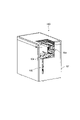
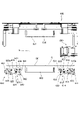
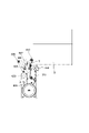
- FIG. 1 is a perspective view of a box-making apparatus according to an embodiment
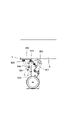
- FIG. 1 is a front view of a box making device according to an embodiment
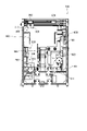
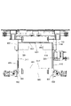
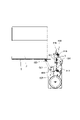
- FIG. Sectional drawing which looked at the box-making apparatus which concerns on embodiment from the front side.
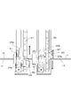
- FIG. 2 is a cross-sectional view mainly showing a corrugated cardboard sheet conveying system of the box making apparatus according to the embodiment.
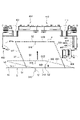
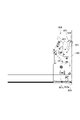
- FIG. 3 is a cross-sectional view of the box manufacturing apparatus according to the embodiment along the direction of insertion of the cardboard sheet.
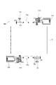
- the perspective view which extracts and shows the structure regarding the opening arm which concerns on embodiment.
- the top view which extracts and shows the structure regarding the opening arm which concerns on embodiment.
- FIG. 9 is a perspective view seen from the side opposite to FIG. 8 ;
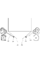
- FIG. 4 is a plan view showing a pressing arm and a tape unit according to the embodiment, together with a state in which the cardboard sheet is being opened.
- FIG. 4 is a perspective view extracting and showing the configuration of the pressing arm and the first flap bending arm according to the embodiment;
- FIG. 4 is a side view showing the configuration of the pressing arm and the first flap bending arm extracted from the embodiment;
- FIG. 4 is a side view showing the configuration of one side of the pressing arm and the first flap bending arm extracted from the embodiment;
- FIG. 4 is a plan view showing the configuration of the pressing arm and the restricting arm according to the embodiment;
- FIG. 4 is a plan view showing a state in which a corrugated cardboard sheet is shaped into a box shape by a pressing arm and a regulating arm according to the embodiment;
- the top view which extracts and shows the 2nd flap bending arm which concerns on embodiment.
- the perspective view which extracts and shows the 2nd flap bending arm which concerns on embodiment.
- FIG. 4 is a front view showing a state before bending the second flap by the second flap bending arm according to the embodiment; The front view which shows the bending state of the 2nd flap by the 2nd flap bending arm which concerns on embodiment.
- FIG. 11 is a front view showing a state when the second flap is finished being bent by the second flap bending arm according to the embodiment;
- FIG. 2 is a side view showing an extracted tape unit according to the embodiment;
- FIG. 23 is a side view seen from the opposite side of FIG. 22;
- FIG. 4 is a side view showing a state before the tape is pasted by the tape unit according to the embodiment; 4 is a perspective view showing the tape unit extracted from the embodiment;
- FIG. FIG. 25 is a side view seen from the side opposite to FIG. 24;
- FIG. 25 is a side view seen from the opposite side of FIG. 25;
- FIG. 4 is a cross-sectional view showing a standby state of the tape unit according to the embodiment;
- FIG. 4 is a cross-sectional view showing a state where the tape of the tape unit according to the embodiment starts to be attached.
- FIG. 4 is a cross-sectional view showing a state in the middle of attaching the tape of the tape unit according to the embodiment;
- FIG. 5 is a cross-sectional view showing a state in which the first tape pressing roller is detached from the bottom surface while the tape is being applied to the tape unit according to the embodiment;
- FIG. 4 is a cross-sectional view showing a cut state of the tape of the tape unit according to the embodiment;
- FIG. 4 is a cross-sectional view showing a state after cutting the tape of the tape unit according to the embodiment;
- FIG. 5 is a cross-sectional view showing a state in which the second tape pressing roller has reached a corner portion while the tape is being applied to the tape unit according to the embodiment;
- FIG. 4 is a cross-sectional view showing a state in which the tape of the tape unit according to the embodiment has been pasted.
- FIG. 4 is a perspective view showing a state in which the tape of the tape unit according to the embodiment is exposed;
- FIG. 4 is a perspective view showing a state in which the tape fixing plate of the tape unit according to the embodiment is removed; The perspective view seen from the direction different from FIG. 36A.
- FIG. 4 is a perspective view showing a state in which the tape is removed from the tape unit according to the embodiment; The side view which shows the state which the tape unit which concerns on embodiment contact
- FIG. 2 is a control block diagram of the box manufacturing device according to the embodiment; 4 is a flow chart of control from insertion of the cardboard sheet to the insertion position according to the embodiment. 4 is a flow chart of control from unboxing of the cardboard sheet to bending of the first flap according to the embodiment. 6 is a flow chart of control from bending of the second flap to tape attachment according to the embodiment. 4 is a flow chart of preparation for taking out the cardboard according to the embodiment.
- FIG. 1 An embodiment will be described with reference to FIGS. 1 to 44.
- FIG. 1 First, the overall configuration of a box manufacturing apparatus 100 of the present embodiment will be described with reference to FIGS. 1 to 4.
- FIG. 1 the overall configuration of a box manufacturing apparatus 100 of the present embodiment will be described with reference to FIGS. 1 to 4.
- FIG. 1 the overall configuration of a box manufacturing apparatus 100 of the present embodiment will be described with reference to FIGS. 1 to 4.
- the box manufacturing apparatus 100 of this embodiment includes a housing 101, a transport mechanism 200, an opening mechanism 300, a first pressing mechanism 400, a first flap bending mechanism 500, and a regulating mechanism 600 (see FIGS. 15, etc.), a second flap bending mechanism 700 (see FIG. 18, etc.), a tape unit 800, and the like.
- the box making apparatus 100 of the present embodiment when a cardboard sheet folded into a plate shape is inserted, the inserted cardboard sheet is opened inside the housing 101 to form a tubular shape, and one side flap of the tubular shape is folded. A box-shaped corrugated cardboard with a flap on the other side of the cylinder is automatically assembled by pasting the tape.
- the housing 101 is formed with an insertion opening 102 for a cardboard sheet and an ejection opening 103 for an assembled cardboard box on the front side when the operator operates the front side.
- an insertion opening 102 and an ejection opening 103 are formed in the front surface of the apparatus so that the cardboard sheet can be inserted and the assembled cardboard can be ejected from the same direction.
- An operation unit 104 such as an apparatus start button and a stop button is provided on the front surface of the housing 101 .
- the operation unit 104 may be provided with a display unit such as a lamp or a screen for displaying the status of the apparatus.
- the insertion opening 102 is a slit that is formed along the top and bottom of the housing 101 from the center to the left in the left-right direction and from the center in the up-down direction to the bottom. Therefore, the operator inserts the corrugated cardboard sheet upright into the box manufacturing apparatus 100 through the insertion opening 102 .
- the position of the insertion opening 102 will be described by exemplifying the arrangement on the left side of the center, but the insertion opening 102 may be positioned on the right side of the center.
- the extraction port 103 is formed above the insertion port 102 continuously with the insertion port 102 and has a wider opening area than the insertion port 102 . Specifically, it has an opening area from which the assembled corrugated cardboard can be taken out.
- the take-out port 103 is open from the front surface to the upper surface of the housing 101, making it easy to take out the assembled corrugated cardboard.
- the left side edge of the ejection port 103 and the left side edge of the insertion port 102 are formed on the same line in the vertical direction.
- FIG. 3 is a cross-sectional view of the internal configuration of the box manufacturing device 100 as seen from the front side.
- mechanisms and units such as a transport mechanism 200, an opening mechanism 300, a first pressing mechanism 400, and a first flap bending mechanism 500 are arranged inside the housing 101.
- the transport mechanism 200 is arranged at a position overlapping the insertion port 102 with respect to the cardboard sheet insertion direction (the direction from the front side to the rear side).
- a conveying roller 201 for conveying a cardboard sheet inserted through an insertion port 102 is arranged below the apparatus, and the cardboard sheet is nipped between the conveying roller 201 and conveyed above the apparatus.
- a driven roller 202 is arranged for this purpose.
- an opening mechanism 300 for opening the cardboard sheet is arranged above the device and below the driven roller 202 .
- the opening mechanism 300 has a first opening arm 310 and a second opening arm 320 arranged to sandwich the cardboard sheet inserted from the insertion opening 102 at the home position in the thickness direction.
- the first opening arm 310 and the second opening arm 320 are arranged so as to face the upper flap of the cardboard sheet.
- a tape unit 800 is arranged in the substantially central portion in the left-right direction inside the housing 101 .
- the tape unit 800 moves in the front-rear direction (direction parallel to the insertion direction of the cardboard sheet) to apply the tape to the lower flap of the cardboard, as will be described later in detail. Since the tape unit 800 is positioned substantially in the center in the left-right direction, when opening the cardboard sheet in the left-right direction as will be described later, the tape unit 800 is positioned in either the front-rear direction (the front side in this embodiment) so as not to interfere with the cardboard sheet. are evacuating.
- a first pressing mechanism 400 and a first flap bending mechanism 500 are arranged on the right side of the tape unit 800 .
- the first pressing mechanism 400 has first pressing portions 410 (420) arranged on both sides in the front-rear direction, and moves in the front-rear direction so as to approach each other. Then, the front and rear sides of the opened cardboard sheet are pressed by the opening mechanism 300 to shape the cardboard sheet into a cylindrical shape.
- the first flap bending mechanism 500 has first bending arms 510 (520) supported below first pressing portions 410 (420) on both sides in the front-rear direction.
- the first bending arm 510 (520) is movable in the front-rear direction together with the first pressing portion 410 (420), and when the first pressing portion 410 (420) presses the front and rear side surfaces of the cardboard sheet, Fold the first flaps connected to the front and back sides of the lower side of the cardboard sheet.
- a one-side regulating member 650 that regulates the position of the right side of the cardboard sheet opened by the opening mechanism 300 is provided.
- the other-side regulating member 660 is provided to regulate the position of the left side surface of the cardboard sheet.
- the other-side regulating member 660 guides the left side surface of the cardboard sheet when the cardboard sheet is inserted through the insertion opening 102 .
- an upper flap pressing roller 670 is arranged to press the upper flap of the opened cardboard sheet.
- the upper flap pressing roller 670 is a driven roller having a rotation axis parallel to the left-right direction, and can guide the upper flap of the opened cardboard sheet in the front-rear direction.
- a scooping member 671 is provided below the first pressing mechanism 400 and the first flap bending mechanism 500 .
- the range in which the tape unit 800 moves includes the opening during opening. A member that supports the bottom edge of the cardboard sheet cannot be placed.
- the pick-up member 671 is arranged on the right side of the tape unit 800 and below the first pressing mechanism 400 and the first flap bending mechanism 500 so that the lower end of the cardboard sheet being opened is taped in the left-right direction.
- the lower end After passing through the unit 800, the lower end is scooped up by a scooping member 671 to prevent the cardboard sheet from tilting. Further, the scooping member 671 is inclined downward toward the left side, so that even if the lower end of the cardboard sheet being opened is slightly lowered, it can be guided to be lifted upward.
- a regulation mechanism 600 (see FIGS. 3, 15, etc.) and a second flap bending mechanism 700 (see FIGS. 3, 18, etc.) are arranged.
- the regulating mechanism 600 is arranged on the left side of FIG. 3, and as will be described later, regulates the positions of the front and rear side surfaces of the cardboard sheet together with the first pressing portions 410 (420) by means of regulating arms 610 and 620 arranged in the front-rear direction. to shape the cardboard sheet into a cylinder.
- the second flap bending mechanism 700 bends the second flap on the lower side of the cardboard sheet by means of second bending arms 710 and 720 arranged on both sides in the left-right direction in FIG. Each configuration will be described in detail below.
- FIG. 1 A configuration for inserting a cardboard sheet will be described with reference to FIGS. 4 and 5.
- FIG. The cardboard sheet inserted through the insertion port 102 as described above is conveyed to the back side (rear side) by the conveying mechanism 200 .
- the transport mechanism 200 has a transport roller 201 , a driven roller 202 , a first detection sensor 203 , a second detection sensor 204 , a tip stopper 205 , a transport roller driving mechanism 210 and a roller elevating mechanism 220 .
- the conveying roller 201 is arranged substantially in the center in the front-rear direction, and conveys the cardboard sheet to the back side by coming into contact with the lower end of the inserted cardboard sheet.
- the conveying roller 201 is rotationally driven by a conveying roller driving mechanism 210 . Further, the conveying roller 201 can be vertically moved by a roller elevating mechanism 220 .
- the conveying roller 201 is positioned at a retracted position (lower position) where the cardboard sheet is not nipped with the driven roller 202. After the cardboard sheet is inserted to some extent, the conveying roller 201 is moved to the conveying position ( upper position), the cardboard sheet is nipped with the driven roller 202, and conveyed to the back side.
- the reason why the conveying roller 201 is positioned at the retracted position when inserting the cardboard sheet is as follows. First, if the conveying roller 201 is at the conveying position when the cardboard sheet is inserted, the operator may come into contact with the conveying roller 201 when inserting the cardboard sheet manually, which may interfere with the insertion. That is, since the operator may feel a sense of incongruity such as a feeling of bumping into the cardboard sheet when inserting the cardboard sheet, the conveying roller 201 is positioned at the retracted position when the cardboard sheet is inserted manually.
- the transport roller 201 when the transport roller 201 is moved from the retracted position to the transport position, the transport roller 201 is rotated. This is because it can be smoothly conveyed without giving a sense of discomfort. If the cardboard sheet is nipped and then the conveying roller 201 is rotated, the cardboard sheet inserted by the operator is temporarily stopped and then conveyed. This may cause the operator to feel as if the cardboard sheet is being pulled suddenly, and may feel a sense of incompatibility.
- a plurality of driven rollers 202 are arranged in the front-rear direction, and guide the cardboard sheet to the depth side while regulating the upper end position of the cardboard sheet by coming into contact with the upper end of the inserted cardboard sheet.
- the two driven rollers 202 arranged on the outer side in the front-rear direction are spaced apart from each other in the front-rear direction, and are arranged so as to sandwich the conveying roller 201 in the front-rear direction.
- the central driven roller 202 is located between the first open arm 310 and the second open arm 320 in the front-rear direction, as shown in FIG. 7, which will be described later. This is done by bringing the driven roller 202 into contact with the portion of the cardboard sheet (in this embodiment, one of the plate-like portions S1) to which force acts during the opening operation of the cardboard sheet, thereby preventing the cardboard sheet from tilting during the opening operation. This is for more efficient suppression.
- the driven roller 202 is positioned between the conveying roller 201 and the cardboard sheet in the vertical direction, which is a direction orthogonal to the conveying direction of the conveying roller 201 . can be nipped.
- the first detection sensor 203 is arranged in the vicinity (entrance) of the insertion port 102 and detects that a cardboard sheet has been inserted through the insertion port 102 .
- the first detection sensor 203 is composed of, for example, a sensor flag that protrudes into the conveying path of the cardboard sheet and is swingably provided so as to be retractable from the conveying path, and a sensor that detects the swinging position of the sensor flag. ing.
- This sensor is, for example, a photointerrupter.
- the tip of the cardboard sheet hits the sensor flag, causing the sensor flag to fall down, thereby changing the logic of the sensor.
- the insertion of the cardboard sheet is detected by the first detection sensor 203 .
- the driving of the conveying roller 201 is started.
- the first detection sensor 203 also detects the driving stop timing of the conveying roller 201, as will be described later. That is, when the cardboard sheet is conveyed to a predetermined insertion position, the rear end of the cardboard sheet passes the first detection sensor 203 and the sensor flag is raised. Then, the logic of the sensor changes and it is detected that the rear end of the cardboard sheet has passed the first detection sensor 203 . Then, the transportation of the cardboard sheet is stopped by stopping the driving of the transportation roller 201 based on the timing when the first detection sensor 203 detects that the rear end of the cardboard sheet has passed.
- the second detection sensor 204 is arranged near the downstream side of the transport roller 201 in the transport direction. Similarly to the first detection sensor 203, the second detection sensor 204 also has, for example, a sensor flag that protrudes into the conveying path of the cardboard sheet and is swingably provided so as to be retracted from the conveying path. It is composed of a sensor that detects the position. When the tip of the cardboard sheet hits the sensor flag and the sensor flag falls, the logic of the sensor changes. Thereby, it is detected that the cardboard sheet has passed the position of the second detection sensor 204 . In this embodiment, when the passage of the cardboard sheet is detected by the second detection sensor 204, the conveying roller 201 from the retracted position starts to move to the upper position, as will be described later. By bringing the conveying roller 201 into contact with the lower end of the cardboard sheet, the cardboard sheet is nipped between the conveying roller 201 and the driven roller 202, and the conveying roller 201 starts conveying the cardboard sheet.
- the leading end stopper 205 is provided further downstream in the transport direction than the second detection sensor 204, and the leading end of the cardboard sheet transported by the transport roller 201 abuts against it to restrict further transport of the cardboard sheet.
- a state in which the cardboard sheet abuts against the front end stopper 205 is a predetermined insertion position, and expansion of the cardboard sheet is started based on this insertion position.
- the transport roller drive mechanism 210 has a roller drive motor 211 and a drive transmission mechanism 212 .
- the driving force of the roller drive motor 211 is transmitted to the conveying roller 201 via the drive transmission mechanism 212 .
- the drive transmission mechanism 212 has a first pulley 213 , a second pulley 214 , a third pulley 215 , a fourth pulley 216 , a first belt 217 and a second belt 218 .
- a first pulley 213 is fixed to the drive shaft of the roller drive motor 211 , and a first belt 217 is stretched between the first pulley 213 and the second pulley 214 .
- a third pulley 215 is arranged coaxially with the second pulley 214 and rotates with the second pulley 214 .
- a second belt 218 is stretched between the third pulley 215 and the fourth pulley 216 .
- a fourth pulley 216 is fixed to the rotation shaft of the conveying roller 201 .
- the rotation of the roller drive motor 211 is transmitted to the conveying roller 201 through the first pulley 213, first belt 217, second pulley 214, third pulley 215, second belt 218, and fourth pulley 216 in this order.
- the conveying roller 201 can swing vertically about the rotation shafts of the second pulley 214 and the third pulley 215 as the swing shaft 219 .
- driving is transmitted from the motor to the transport roller 201 by two pulley transmission mechanisms in order to swing the transport roller 201 up and down. It should be noted that other mechanisms such as a gear mechanism may be used as long as both the vertical movement of the conveying roller 201 and the drive transmission from the motor can be achieved.
- the roller elevating mechanism 220 as a nip releasing means is capable of nipping the cardboard sheet by the conveying roller 201 and the driven roller 202 and releasing the nip.
- a roller elevating mechanism 220 has an elevating drive motor 221 , an elevating arm 222 and an elevating cam 223 .
- the rotational driving force of the elevation drive motor 221 is transmitted to the elevation cam 223 by a drive transmission mechanism such as a pulley.
- the elevation cam 223 is an eccentric cam, and the distance from the rotation center to the outer peripheral surface (cam surface) varies depending on the rotation angle.
- the elevating arm 222 is supported so as to be able to swing about the above-described swing shaft 219.
- One end of the elevating arm 222 rotatably supports the conveying roller 201, and the other end of the elevating arm 222 is in contact with the lower surface of the elevating cam 223. are placed in
- the elevation cam 223 When the elevation cam 223 is rotated by driving the elevation drive motor 221, the elevation arm 222 swings around the swing shaft 219 to move the conveying roller 201 in the vertical direction. In FIG. 5, both the case where the conveying roller 201 is at the conveying position and the case where it is at the retracted position are superimposed.
- the elevating cam 223 lifts the elevating arm 222, the transport roller 201 descends to the retracted position.
- the elevating cam 223 rotates from this position and the elevating arm 222 descends, the transport roller 201 rises to the transport position.
- the elevation of the conveying roller 201 is detected by a conveying roller elevation sensor 224 .
- the transport roller elevation sensor 224 detects the position of the elevation arm 222, for example.
- the conveying roller 201 stands by at a position retracted downward from the conveying path. This position is the default position of the conveying roller 201 .
- the elevation drive motor 221 starts rotating, and the conveying roller 201 is raised to the transport position (S104). That is, by rotating the elevation drive motor 221, the elevation cam 223 is rotated, and the elevation arm 222 in contact with the cam surface swings around the swing shaft 219. FIG. Then, the conveying roller 201 is moved from the retracted position to the conveying path (conveying position) and brought into contact with the lower end of the cardboard sheet.
- the conveying roller 201 After the conveying roller 201 contacts the cardboard sheet, the cardboard sheet is conveyed by the conveying roller 201 . At this time, the operator feels an operational feeling that the cardboard sheet is automatically conveyed while the cardboard sheet is being inserted. Then, even if the trailing edge of the cardboard sheet passes the first detection sensor 203 and the logic of the sensor changes (OFF), the rotation of the conveying roller 201 continues for a while (S105).
- the rotation of the conveying roller is continued for a time corresponding to a distance longer than the predetermined distance at which the leading end of the cardboard sheet abuts against the leading end stopper 205 .
- the cardboard sheet is stopped and the conveying roller 201 is slipping. This is to stop the cardboard sheet in a state in which the cardboard sheet is reliably in contact with the tip stopper 205 . That is, the reason is that the stop position of the cardboard sheet is to be determined.
- the elevation drive motor 221 is driven to swing the elevation arm 222 and lower the conveying roller 201 to the retracted position (S107). That is, after the cardboard sheet is conveyed to the insertion position by the conveying roller 201, the nip between the conveying roller 201 and the driven roller 202 is released. Further, after a certain period of time has elapsed, the rotation of the conveying roller 201 is stopped (S108). In this state, the cardboard sheet is positioned at a predetermined insertion position within the housing 101 .
- the cardboard sheet when the cardboard sheet is conveyed, the cardboard sheet is nipped by the conveying roller 201 and the driven roller 202, and the vertical position of the cardboard sheet is regulated.
- the transport roller 201 is retracted to release the vertical positional regulation of the cardboard sheet (that is, release the nip). This is to smoothly open the folded cardboard sheet in the opening operation described below.
- FIG. 6 A structure relating to the opening of the cardboard sheet will be described with reference to FIGS. 6 to 11.
- FIG. The corrugated cardboard sheet S inserted into the insertion position as described above is opened by the opening mechanism 300 and shaped into a substantially cylindrical shape with a substantially rectangular cross section.
- the opening mechanism 300 has a first opening arm 310, a second opening arm 320, and the like. As shown in FIGS. 6 and 7, the first opening arm 310 and the second opening arm 320 are arranged at the home position so as to sandwich the upper flap of the cardboard sheet S in the insertion position in the thickness direction. As shown in FIGS. 2 and 3, the first opening arm 310 is on standby at a position on the left side of the other side regulating member 660 .
- the second open arm 320 waits at a position on the right side of the right edge of the insertion opening 102 . These standby positions allow the cardboard sheet S inserted by the operator to be guided between the first opening arm 310 and the second opening arm 320 . Also, the first opening arm 310 and the second opening arm 320 are arranged at positions shifted from each other in the front-rear direction.
- the cardboard sheet S is conveyed between the first opening arm 310 and the second opening arm 320 by the above-described conveying configuration.
- the distance from the tip of the cardboard sheet S to be inserted to a gap (slit) between flaps, which will be described later, is defined in advance, and the first opening arm 310 and the opening arm 310 are positioned at the defined position.
- a second opening arm 320 is arranged.
- the arrangement of the first opening arm 310 and the second opening arm 320 is based on the tip stopper 205 . Therefore, as described above, the tip of the corrugated cardboard sheet S is reliably brought into contact with the tip stopper 205 . In order to ensure that the leading edge of the cardboard sheet S abuts against the leading edge stopper 205 , as described above, after the cardboard sheet is detected by the second detection sensor 204 , a pulse or The conveying roller 201 is rotated more than the distance.
- the corrugated cardboard sheet S used in the box making device 100 of the present embodiment has a rectangular shape when viewed from the flap side when assembled (box made) as a box-shaped corrugated cardboard. Therefore, the pair of plate-like portions S1 and S2 facing each other in a state in which the cardboard is folded into a plate-like shape has a pair of flaps of different lengths. A pair of flaps are provided adjacent to each other in the state of a cardboard sheet. A pair of flaps having different lengths are provided on both end sides of the plate-like portions S1 and S2 (both ends in the vertical direction at the insertion position). Generally, there is a gap between a pair of adjacent flaps, but in the case of corrugated cardboard having a rectangular shape when viewed from the flap side as described above, the position of this gap is between the pair of plate-like portions S1 and S2. different in
- the flaps located on both sides in the front-back direction are referred to as the first flaps F1
- the flaps located on both sides in the left-right direction are referred to as the second flaps F2.
- the first opening arm 310 is arranged downstream (rear side) in the insertion direction of the cardboard sheet S from the second opening arm 320, and as will be described later, the first opening arm 310
- the corrugated cardboard sheet S is opened by moving to the right side.
- the first flap F1 is shorter in length than the second flap F2, and the pair of plate-like portions S1 and S2 provided on one of the plate-like portions S1 on the left in the insertion position has a pair of The gap between the flaps F1 and F2 (hereinafter referred to as the first gap G1) is behind the gap between the pair of flaps F1 and F2 (hereinafter referred to as the second gap G2) provided on the other plate-shaped portion S2 on the right side. To position.
- the shape of the cardboard and the direction in which the cardboard sheet S is inserted are predetermined, and the first gap G1 and the second gap G2 are formed in the state of the cardboard sheet folded into a plate. It is suitable for making corrugated cardboard boxes that do not overlap. That is, the box making apparatus 100 of the present embodiment opens the cardboard sheet S by utilizing the fact that there is a flap facing the gap in the state of the folded cardboard sheet.
- FIG. 6 there is a second flap F2 on the side of the plate-like portion S2 facing the first gap G1 on the side of the plate-like portion S1, and the second flap F2 on the side of the plate-like portion S2 faces the second gap G2. Then, there is a second flap F2 on the side of the plate-like portion S1. Then, by inserting the first opening arm 310 into the first gap G1 and further moving the first opening arm 310, the second flap F2 of the opposing plate-like portion S2 is pushed. Similarly, by inserting the second opening arm 320 into the second gap G2 and further moving the second opening arm 320, the second flap F2 of the opposing plate-like portion S1 is pushed. In this embodiment, the cardboard sheet S is opened by moving the first opening arm 310 by a large amount.
- the order of the first gap G1 and the second gap G2 is always the same with respect to the insertion direction (front-rear direction).
- the positions of the labels affixed to the corrugated cardboard and the printing position are almost the same for the same type of corrugated cardboard. Therefore, in actual work, it is common to insert the cardboard sheets S in the same direction.
- the opening structure of the cardboard sheet will be specifically described below.
- the first opening arm 310 as an opening arm is attached to one plate-like portion S1 of a pair of opposing plate-like portions S1 and S2 of the cardboard sheet S folded into a plate shape. It is a plate-shaped member having a thickness narrower than the gap (first gap G1) between a pair of flaps (between the first flap F1 and the second flap F2) provided so as to be adjacent to each other.
- the length of the first opening arm 310 is shorter than the length of the first gap G1.
- the first opening arm 310 is fixed to a first moving block 310a, and the first moving block 310a is movable along a first guide rail 311 arranged in the left-right direction.
- the first opening arm 310 is moved by a first opening motor (left opening motor) 312 as moving means. Specifically, the drive of the first opening motor 312 is transmitted to the first opening arm 310 via the first opening mechanism 313 to move the first opening arm 310 in the left-right direction.
- the first opening mechanism 313 has a pulley 314 , a pulley 315 and a belt 316 .
- the pulley 314 is connected to the drive shaft of the first opening motor 312 by a drive transmission mechanism such as a pulley mechanism.
- a belt 316 is stretched between the pulleys 314 and 315 .
- a first moving block 310 a is fixed to the belt 316 .
- the pulley 314 rotates and the belt 316 moves around.
- the movement of the belt 316 causes the first moving block 310 a and the first opening arm 310 to move along the first guide rail 311 .
- a first home position detection sensor (left opening arm_HP sensor) 317 that detects that the first opening arm 310 is positioned at the home position, and the first opening arm 310 move to the first predetermined position.
- a first arm position detection sensor (left open arm position sensor) 318 that detects the opening.
- Both detection sensors 317 and 318 are photointerrupters having a light-emitting portion and a light-receiving portion facing each other, and can pass through the first flag 310b provided on the first moving block 310a. Both detection sensors 317 and 318 detect the position of the first opening arm 310 by detecting passage of the first flag 310b.
- the second opening arm 320 is arranged so as to be adjacent to the other plate-like portion S2 of the pair of opposing plate-like portions S1 and S2 of the cardboard sheet S folded into a plate. It is a plate-shaped member having a thickness narrower than the gap (second gap G2) between the provided pair of flaps (between the first flap F1 and the second flap F2). The length of the second opening arm 320 is shorter than the length of the second gap G2.
- the second opening arm 320 is fixed to a second moving block 320a, and the second moving block 320a is movable along a second guide rail 321 arranged in the horizontal direction.
- the second opening arm 320 is moved by a second opening motor (right opening motor) 322, as shown in FIG. Specifically, the drive of the second opening motor 322 is transmitted to the second opening arm 320 via the second opening mechanism 323 to move the second opening arm 320 in the left-right direction.
- the second opening mechanism 323 has a pulley 324 , a pulley 325 and a belt 326 .
- the pulley 324 is connected to the drive shaft of the second opening motor 322 by a drive transmission mechanism such as a pulley mechanism.
- a belt 326 is stretched between the pulleys 324 and 325 .
- a second moving block 320 a is fixed to the belt 326 .
- the pulley 324 rotates and the belt 326 circulates.
- the movement of the belt 326 causes the second moving block 320 a and the second opening arm 320 to move along the second guide rail 321 .
- a second home position detection sensor (right opening arm_HP sensor) 327 that detects that the second opening arm 320 is positioned at the home position, and the second opening arm 320 move to the second predetermined position.
- a second arm position detection sensor (right opening arm position sensor) 328 for detecting that the opening has been opened.
- Both of these detection sensors 327 and 328 are photointerrupters having a light-emitting portion and a light-receiving portion facing each other, through which the second flag 320b provided on the second moving block 320a can pass. Both detection sensors 327 and 328 detect the position of the second opening arm 320 by detecting passage of the second flag 320b.
- the first arm position detection sensor 318 and the second arm position detection sensor 328 may be omitted if position control is possible using motor pulses or the like.
- the first opening motor 312 When opening the cardboard sheet S with the above configuration, the first opening motor 312 is driven to move the first opening arm 310 rightward from the home position shown in FIGS. At this time, as shown in FIGS. 10 and 11, the first opening arm 310 pushes the second flap F2 provided on the other plate-like portion S2 so that the other plate-like portion S2 is separated from the one plate-like portion S1. move away. Further, the first opening arm 310 is arranged so as to push the second flap F2 and move the other plate-like portion S2 with reference to the insertion position described above.
- the cardboard sheet S When the cardboard sheet S is inserted into the insertion position by the above-described transport configuration, the cardboard sheet S is nipped by the transport roller 201 and the driven roller 202 . Since it is difficult to open the cardboard sheet S in this state, in this embodiment, after the cardboard sheet S is inserted into the insertion position by the transport roller 201, the roller elevating mechanism 220 is operated to form a nip between the transport roller 201 and the driven roller 202. cancel. Then, after the nip is released, the movement of the first opening arm 310 is started.
- the corrugated cardboard sheet S is nipped again after a predetermined time has passed since the first opening arm 310 started to move.
- This predetermined time is the time required for the other plate-like portion S ⁇ b>2 to reach a position away from the conveying roller 201 with respect to the rotational axis direction of the conveying roller 201 . That is, the other plate-like portion S2 is moved to a position where the other plate-like portion S2 is not nipped even if the nipping operation is performed again, and only one plate-like portion S1 is nipped.
- the predetermined time is preferably set to the time before the other plate-like portion S2 moved by the first opening arm 310 reaches the moving path of the tape unit 800. This is because the corrugated cardboard sheet tends to tilt when it moves to this point.
- the second opening arm 320 is in the second gap G2 while the first opening arm 310 pushes the second flap F2 provided on the other plate-like portion S2 to move the other plate-like portion S2.
- it abuts on the second flap F2 provided on one plate-like portion S1 and at a position facing the second gap G2. That is, when the first opening arm 310 moves to the right to enter the first gap G1, the second opening arm 320 also moves to the left to enter the second gap G2 and abut the second flap F2.
- the other plate-like portion S2 is moved away from the one plate-like portion S1 by the first opening arm 310.
- FIG. As a result, the cardboard sheet S is opened.
- the shape of the cardboard sheet S changes from a plate shape to a parallelogram.
- the four sides of the parallelogram shown in FIG. 11 constitute four side plate portions D11, D12, D21 and D22 of the cylindrical cardboard.
- one plate-like portion S1 is formed by the side plate portions D11 and D12
- the other side plate portion S1 is formed by the side plate portions D11 and D12.
- a plate-like portion S2 is composed of a side plate portion D21 and a side plate portion D22.
- a first flap F1 is provided on the short side plate portions D11 and D21
- a second flap F2 is provided on the long side plate portions D12 and D22.
- the first opening arm 310 pushes the second flap F2 provided on the other plate-like portion S2 to move the other plate-like portion S2 upward in FIG. 11, the side plate portion D11 of the one plate-like portion S1, The side plate portion D21 of the other plate-like portion S2 rises clockwise in FIG. Then, the side plate portion D22 of the other plate-like portion S2 moves away from the side plate portion D12 of the one plate-like portion S1. At this time, since the movement of the second flap F2 provided on the side plate portion D12 of one plate-like portion S1 is restricted by the second opening arm 320, the side plate portion D12 does not move. Also, the second opening arm 320 passes through the second gap G2 between the flaps provided in the other plate-like portion S2. The width of the second opening arm 320 (the length in the vertical direction in FIG. 11) is set to a length such that the second gap G2 can be smoothly removed from the second opening arm 320 .
- the side plate portions D11 and D21 are rotated clockwise to open the cardboard sheet S. ing.
- one plate-like portion S1 is deformed so as to stand up from the back side. This is because the tape unit 800 is located at the front side in the housing 101 at the home position, and is located at the home position during the opening operation, as will be described later.
- the tape unit 800 is separated from the area where the cardboard sheet S is opened in order to prevent interference with the tape unit 800. can be considered. In this case, the size of the device is increased. On the other hand, if the rising direction of one plate-like portion S1 is set in relation to the home position of the tape unit 800 as in this embodiment, interference between the cardboard sheet S and the tape unit 800 during the opening operation can be prevented.
- the home position of the tape unit 800 is set to the rear side of the housing 101, and one plate-like portion S1 is raised from the front side during the opening operation, that is, the side plate portions D11 and D21 are rotated counterclockwise.
- the first opening arm 310 moves until it is detected by the first arm position detection sensor 318, that is, to the first predetermined position.
- the cardboard sheet S is opened only to the state of a parallelogram. Then, with the cardboard sheet S in this shape, the first pressing mechanism 400 is operated. This point will be described later.
- the opening arms move in opposite directions. That is, if the positional relationship of the gaps between the flaps provided on the pair of plate-shaped portions is opposite to that described above, for example, the positions of the first opening arm 310 and the second opening arm 320 at the home positions are reversed left and right, The cardboard sheet S is opened by largely moving the second opening arm 320 to the right.
- the front and rear positions of the first opening arm 310 and the second opening arm 320 can be adjusted, even if the shapes of the cardboard boxes are different and the positions of the first gap G1 and the second gap G2 are misaligned, it can be handled. It is possible. That is, in the case of the configuration described above, the positions of the first opening arm 310 and the second opening arm 320 are fixed in the front-rear direction, but they can also be configured to be movable in the direction in which the cardboard sheet is conveyed.
- a sensor is provided for measuring the distance from the tip of the cardboard sheet to the gap between the flaps, and at least one of the first opening arm 310 and the second opening arm 320 is adjusted according to the length detected by the sensor.
- the position of the opening arm of is moved in the conveying direction of the cardboard sheet.
- the second detection sensor 204 detects in the same manner as described above in order to ensure that the front end of the corrugated cardboard sheet material hits the front end stopper 205. After that, the conveying roller 201 is rotated more than the expected pulse or distance at which the front end of the cardboard sheet hits the front end stopper 205 .
- the cardboard sheet since the cardboard sheet is opened by the first opening arm 310 and the second opening arm 320 as described above, the cardboard sheet can be made smaller than, for example, a configuration in which the side surface of the cardboard sheet is sucked and opened. That is, when the cardboard sheet is opened by suction, a suction device such as a vacuum pump is required, which increases the size of the device.
- the opening arm in the case of the configuration in which the cardboard sheet is opened by moving the opening arm as in the present embodiment, the opening arm can be moved by driving the motor, so that the size can be significantly reduced compared to the configuration using a vacuum pump or the like. I can plan.
- the cardboard sheet is opened by inserting the opening arm into the gap between the flaps and pressing and moving the flap facing the gap, it can be used as long as the cardboard is rectangular, so it is highly versatile. .
- the first opening arm 310 and the second opening arm 320 remain inside the opened cardboard sheet.
- a suction device such as a vacuum pump
- excessive force is less likely to be applied during the opening operation, it is possible to suppress damage to the corrugated cardboard when assembling the cardboard.
- FIG. 11 A configuration relating to cylindrical shaping of the cardboard sheet and bending of the first flap F1 will be described with reference to FIGS. 11 to 14.
- FIG. 11 As described above, in the opening operation of the cardboard sheet S by the first opening arm 310 and the second opening arm 320, the cardboard sheet S is opened only to the parallelogram state as shown in FIG.
- the first pressing mechanism 400 is operated with the cardboard sheet S in this shape to shape the cardboard sheet S into a rectangular shape when viewed from the flap side. Further, in this embodiment, the first flap bending mechanism 500 is operated in conjunction with the movement of the first pressing mechanism 400 .
- the first pressing portions 410 and 420 of the first pressing mechanism 400 are brought into contact with the sides of the cardboard box unfolded by the first opening arm 310 and the second opening arm 320 to regulate the position of the cardboard box in the device. .
- the first pressing parts 410 and 420 of the first pressing mechanism 400 are moved toward the center of the apparatus in order to shape the unfolded cardboard sheet S into a rectangular shape.
- the first flap bending mechanism 500 bends the first flap F1 in conjunction with the operation of the first pressing mechanism 400 .
- the first pressing mechanism 400 has first pressing portions 410 and 420 and the like. As shown in FIGS. 11 to 13, the first pressing portions 410 and 420 are arranged on both sides in the front-rear direction inside the housing 101 so as to sandwich an opening area ⁇ where the opening operation of the cardboard sheet S is performed. . In addition, the first pressing portions 410 and 420 have surfaces facing the opening region ⁇ parallel to the left-right direction and the up-down direction (surfaces perpendicular to the insertion direction of the cardboard sheet S). Further, the first pressing portions 410 and 420 are positioned so as to face the side plate portions D11 and D21 in the height direction, and press the side plate portions D11 and D21 when the corrugated cardboard sheet S is shaped.
- the first pressing portion 410 on the front side is provided with a biasing plate portion 440 via a compression spring 442 on the side facing the opening region ⁇ , that is, on the rear side surface.
- a compression spring 442 is arranged within the cylinder 441 .
- the biasing plate portion 440 has a pressing surface 440a facing the open area ⁇ that is parallel to the left-right direction. The urging plate portion 440 is urged toward the opening region ⁇ , and prevents the side plate portion D21 from being pushed too much when the corrugated cardboard sheet S is formed into a tubular shape, as will be described later.
- the second pressing portion 420 on the rear side has a pressing surface 420a facing the open area ⁇ that is parallel to the left-right direction.
- the second pressing portion 420 is not provided with the biasing plate portion as described above, it may be provided.
- the biasing plate portion 440 or the like may be provided on the second pressing portion 420 side instead of the first pressing portion 410 side.
- Such first pressing parts 410 and 420 are moved in the front-rear direction by driving the first pressing part moving motors 411 and 421, respectively.
- a first pressing portion guide rail 430 (FIG. 12) is arranged in the front-rear direction.
- first pressing portion moving motors 411 and 421 and first pressing portion moving mechanisms 412 and 422 are arranged.
- a first pressing portion guide rail 430 and first pressing portion moving motors 411 and 421 are provided on the side opposite to the transport path of the cardboard sheet S (the position where the transport roller 201 and the driven roller 202 are arranged) across the opening region ⁇ . and first pressing portion moving mechanisms 412 and 422 are arranged.
- the first pressing portions 410 and 420 have surfaces perpendicular to the direction in which the cardboard sheet S is inserted in order to press the side plate portions D11 and D21 when the cardboard sheet S is shaped.
- the first pressing parts 410 and 420 are arranged on the same side as the transport path of the cardboard sheet S, they must be arranged outside the cardboard sheet S (the combined length of D21 and D22) to be inserted into the apparatus. must.
- the cardboard sheet S is opened, the length in the front-rear direction is shortened (length by D22). Since it can be arranged, the apparatus can be made smaller than if it were arranged on the conveying path side.
- the first pressing parts 410 and 420 are supported by the first pressing part guide rails 430 via moving blocks 431 and 432 so as to be freely movable in the front-rear direction. Then, the first pressing portion 410 is driven by the first pressing portion moving motor (right first flap bending and pressing motor) 411, and the second pressing portion 420 is driven by the first pressing portion moving motor (left first flap bending and pressing motor). ) 421 to move along the first pressing portion guide rail 430 .
- the driving of the first pressing portion moving motors 411 and 421 is transmitted to the first pressing portions 410 and 420 via the first pressing portion moving mechanisms 412 and 422 .
- the first pressing portion moving mechanism 412 has pulleys 412a and 412b and belts 412c and 412d.
- a belt 412c is stretched between a drive pulley (not shown) provided on the drive shaft of the first pressing portion moving motor 411 and the pulley 412a, and a belt 412d is stretched between the pulley 412a and the pulley 412b.
- a moving block 431 is fixed to the belt 412d.
- the drive of the first pressing portion moving motor 411 is transmitted to the belt 412c, the pulley 412a, and the belt 412d, and the belt 412d rotates, thereby moving the moving block 431 and the first pressing portion 410 along with the belt 412d to the first pressing portion. It moves along the part guide rail 430 . Therefore, the forward and reverse rotation of the first pressing portion moving motor 411 causes the first pressing portion 410 to move in both the front and rear directions.
- the first pressing portion moving mechanism 422 has pulleys 422a, 422b and belts 422c, 422d.
- a belt 422c is stretched between a drive pulley (not shown) provided on the drive shaft of the first pressing portion moving motor 421 and the pulley 422a, and a belt 422d is stretched between the pulley 422a and the pulley 422b.
- a moving block 432 is fixed to the belt 422d. Therefore, the drive of the first pressing portion moving motor 421 is transmitted to the belt 422c, the pulley 422a, and the belt 422d, and the belt 422d rotates, thereby moving the moving block 432 and the first pressing portion 420 along with the belt 422d to the first pressing portion.
- the forward and reverse rotation of the first pressing portion moving motor 421 causes the first pressing portion 420 to move in both the front and rear directions.
- the drive motor for the first pressing portions 410 and 420 may be shared, in the present embodiment, as described below, the movement start timings of the first pressing portions 410 and 420 are staggered. is driven by a motor of
- the first pressing portion 420 on the rear side starts to move before the first pressing portion 410 on the front side. This is because the opening operation by the first opening arm 310 lifts the other plate-like portion S2 from the rear side, as described above. That is, the corrugated cardboard can be shaped more efficiently by pushing the side of the corrugated cardboard from the lifted side. Note that the first pressing portion 410 on the front side comes into contact with the side surface of the corrugated cardboard pressed by the first pressing portion 420 on the rear side.
- the first pressing portion 410 on the front side and the first pressing portion 420 on the rear side of the cardboard to be shaped move too far toward the center of the device due to variations in the size of the cardboard sheet S, the sides of the cardboard are pushed too much. Become. For this reason, the first pressing portion 410 on the front side is provided with the biasing plate portion 440 via the compression spring 442 as described above.
- the urging plate portion 440 abuts on the side surface of the cardboard with the compression spring 442 stretched.
- the movement of the first pressing part 410 is set to a position in which the compression spring 442 is not completely compressed and is moved according to the predetermined size of the corrugated cardboard to be shaped.
- the variation can be absorbed within the range in which the compression spring 442 is compressed, and deformation of the cardboard can be suppressed.
- the first flap bending mechanism 500 operates in conjunction with the movement of the first pressing mechanism 400 as described above.
- the first flap bending mechanism 500 has first bending arms 510, 520, and the like.
- the first bending arms 510 and 520 open the cardboard sheet S on both sides in the front-rear direction inside the housing 101 in the same manner as the first pressing parts 410 and 420. They are arranged so as to sandwich the open area ⁇ .
- the first bending arms 510, 520 are respectively supported by the first pressing portions 410, 420 and move forward and backward together with the first pressing portions 410, 420.
- each of the first bending arms 510 and 520 is a plate-shaped member whose surface facing the open area ⁇ is parallel to the left-right direction.
- the first bending arm 510 on the front side is swingably supported by the lower end of the first pressing portion 410 .
- the first bending arm 510 is fixed to a rotating shaft 511 that is rotatably supported by the lower end of the first pressing portion 410 .
- the rotation axis direction of the rotation shaft 511 is parallel to the left-right direction, and the first bending arm 510 can swing back and forth about the rotation axis of the rotation shaft 511 .
- the first bending arm 520 on the rear side is swingably supported by the lower end of the first pressing portion 420 .
- the first bending arm 520 is fixed to a rotating shaft 521 that is rotatably supported by the lower end of the first pressing portion 420 .
- the rotation axis direction of the rotation shaft 521 is parallel to the left-right direction, and the first bending arm 520 can swing back and forth about the rotation axis of the rotation shaft 521 .
- Interlocking arms 512 and 522 are fixed to the rotating shafts 511 and 521 described above, respectively, and the interlocking arms 512 and 522 also swing around the rotation axes of the rotating shafts 511 and 521, respectively. That is, the interlocking arm 512 and the first bending arm 510 integrally swing together, and the interlocking arm 522 and the first bending arm 520 integrally swing about the rotational axes of the rotational shafts 511 and 521, respectively.
- Cam followers 513 and 523 are arranged at the tips of the interlocking arms 512 and 522, respectively.
- the cam followers 513 and 523 are rollers rotatably supported at the tips of the interlocking arms 512 and 522, respectively.
- Cam followers 513 and 523 contact cam surfaces 515 and 525 of cam members 514 and 524 arranged below first pressing portion guide rail 430 .
- the cam surface 515 that contacts the cam follower 513 on the front side is an inclined surface that slopes upward toward the rear side.
- the cam surface 525 that contacts the cam follower 523 on the rear side is an inclined surface that is inclined upward toward the front side. That is, the cam surfaces 515 and 525 are slanted surfaces that are slanted in opposite directions.
- the cam followers 513 and 523 are positioned on the lower portions (lower ends in this embodiment) of the cam surfaces 515 and 525. no contact. In this state, the first bending arms 510 and 520 hang down substantially vertically. Then, when the first pressing portions 410 and 420 respectively move in the front-rear direction toward the opening region ⁇ , the cam followers 513 and 523 come into contact with the cam surfaces 515 and 525, and the cam followers 513 and 523 and the cam surfaces 515 and 525 engage with each other.
- the interlocking arms 512 and 522 rotate so that the tips of the interlocking arms 512 and 522 move upward.
- the first bending arms 510 and 520 connected to the interlocking arms 512 and 522 via the rotating shafts 511 and 521 also rotate in the same direction.
- the interlocking arms 512 and 522, the cam followers 513 and 523, and the cam surfaces 515 and 525 cause the first bending arms 510 and 520 to bend in conjunction with the movement of the first pressing portions 410 and 420.
- Interlocking mechanisms 531 and 532 are configured to perform this operation.
- the first flap F1 is folded.
- the opened cardboard sheet S is called cardboard.
- the bending angle of the first flap F1 is an angle at which the first flap F1 is substantially horizontal, or an angle at which the tip is inclined with respect to the horizontal direction so as to point downward.
- the second flap F2 is bent as will be described later. , the first flap F1 is further bent.
- the installation space can be made smaller than when these are provided separately, and the size of the device can be reduced.
- the rotating motion of the first bending arms 510 and 520 is interlocked with the movement of the first pressing portions 410 and 420, the operating mechanism can be simplified and the installation space can be reduced. Therefore, the cost and size of the device can be reduced.
- the first pressing portions 410 and 420 are brought into contact with the side plate portions D11 and D21 of the cardboard. , D21 is folded. That is, these operations are performed in one operation.
- the edge F11 of the first flap F1 may interfere with the edge F21 (see FIG. 9) of the second flap F2, making it difficult to open.
- the first flap F1 if the first flap F1 is folded in a parallelogram state as in the present embodiment, the first flap F1 pushes the second flap F2. It can be smoothly folded without interfering with the edge F21 of the second flap F2.
- FIG. 15 A configuration relating to regulation of cardboard boxes will be described with reference to FIGS. 15 and 16.
- FIG. As described above, in the opening operation of the cardboard sheet S by the first opening arm 310 and the second opening arm 320, the cardboard sheet S is opened only to the parallelogram state as shown in FIG.
- the regulation mechanism 600 is operated, and the side plate portions D11 and D21 extending in the front-rear direction are arranged so that the shape of the corrugated cardboard sheet S viewed from the flap side becomes a rectangular shape. Regulate position.
- first pressing mechanism 400 and the regulation mechanism 600 described above are interlocked with each other to shape the cardboard sheet S into a rectangular shape. At this time, either the first pressing mechanism 400 or the regulation mechanism 600 may start operating first, but in the present embodiment, the regulation mechanism 600 starts operating first.
- the regulation mechanism 600 has regulation arms 610, 620 and the like.
- the regulating arms 610, 620 are rotatable around the rotation axes of the rotation shafts 616, 626, respectively.
- the regulation arms 610 and 620 are on the opposite side to the first pressing portions 410 and 420 in the left-right direction.
- the regulating arms 610 and 620 are arranged at positions facing the first pressing portions 410 and 420 with the insertion position of the cardboard sheet S interposed therebetween.
- the regulation mechanism 600 is arranged on the left side (lower side in FIG. 15) of the transport path of the cardboard sheet S, and the regulation arms 610 and 620 are retracted from the transport path, thereby hindering the transport of the cardboard sheet S. prevent you from doing so.
- the regulation surfaces 610a and 620a of the regulation arms 610 and 620 are parallel to the direction in which the cardboard sheet S is inserted. are evacuating.
- the corrugated cardboard sheet S is opened into a rectangular shape, it rotates across the conveying path to regulate the side surface of the corrugated cardboard.
- restriction arms 610 and 620 are arranged on both sides of the housing 101 in the front-rear direction, similarly to the first pressing portions 410 and 420 .
- the regulating arms 610 and 620 are plate-like members, respectively, and have regulating surfaces 610a and 620a that are parallel to the vertical direction.
- the regulation arms 610 and 620 are driven by the regulation arm drive motors 611 and 621 to rotate about the rotation axes of the rotation shafts 616 and 626 . Drives of the restriction arm drive motors 611 and 621 are transmitted to the restriction arms 610 and 620 via restriction arm drive mechanisms 612 and 622, respectively.
- a regulation arm drive mechanism 612 that transmits drive to the regulation arm 610 on the front side has pulleys 613 and 614 , a belt 615 and a gear train 617 .
- a pulley 613 is provided on the drive shaft of the regulating arm drive motor 611 , and a belt 615 is stretched between the pulleys 613 and 614 .
- Pulley 614 and regulating arm 610 are connected via a gear train 617 .
- Rotation of the regulating arm drive motor 611 is transmitted to the pulley 613 , belt 615 and pulley 614 , and rotation of the pulley 614 is transmitted to the regulating arm 610 via the gear train 617 .
- the regulation arm 610 rotates around the rotation axis of the rotation shaft 616 .
- the rotation direction of the front regulation arm 610 from the retracted position to the regulation position is counterclockwise.
- a regulation arm drive mechanism 622 that transmits drive to the regulation arm 620 on the rear side has pulleys 623 and 624, a belt 625, and a gear train 627.
- a pulley 623 is provided on the drive shaft of the regulating arm drive motor 621 , and a belt 625 is stretched between the pulleys 623 and 624 .
- Pulley 624 and regulating arm 620 are connected via a gear train 627 .
- Rotation of the regulating arm drive motor 621 is transmitted to a pulley 623 , a belt 625 and a pulley 624 , and rotation of the pulley 624 is transmitted to the regulating arm 620 via a gear train 627 .
- the regulation arm 620 rotates around the rotation axis of the rotation shaft 626 .
- the rotation direction of the rear regulation arm 620 from the retracted position to the regulation position is clockwise.
- sensor flags 630 and 631 are provided at the proximal end of the regulation arm (right regulation arm) 610, respectively.
- the sensor flags 630 and 631 are provided at positions with different phases in the rotational direction around the rotary shaft 616, and are detected by a rotational position detection sensor 632 of the right regulating arm.
- the rotational position detection sensor 632 is a photointerrupter and detects that the sensor flag 630 or 631 has passed.
- the sensor flag 630 can detect that the regulation arm 610 is positioned at the retracted position shown in FIG. 15, and the sensor flag 631 can detect that the regulation arm 610 is positioned at the regulation position shown in FIG.
- the retracted position is the home position of the regulation arm 610, and the regulation arm drive motor 611 is stopped at the regulation position by controlling the pulse or time.
- the regulation arm 610 is set to the home position, and the regulation arm drive motor 621 is stopped at the retracted position by controlling the pulse or time.
- sensor flags 640 and 641 are provided at the proximal end of the regulation arm (left regulation arm) 620, respectively.
- the sensor flags 640 and 641 are provided at positions with different phases in the rotational direction around the rotary shaft 626, and are detected by a rotational position detection sensor 642 of the left regulation arm.
- the rotational position detection sensor 642 is a photointerrupter and detects that the sensor flag 640 or 641 has passed.
- a sensor flag 640 can detect that the regulation arm 620 is positioned at the retracted position shown in FIG. 15, and a sensor flag 641 can detect that the regulation arm 620 is positioned at the regulation position shown in FIG.
- the retracted position is the home position of the regulation arm 620, and the regulation arm drive motor 621 is stopped at the regulation position by controlling the pulse or time.
- the regulation arm 620 is set to the home position, and the regulation arm drive motor 621 is stopped at the retracted position by controlling the pulse or time.
- the one-side regulating member 650 and the other-side regulating member 660 are provided on both sides in the left-right direction of the open area ⁇ .
- the one-side regulating member 650 on the right side (upper side in FIG. 15) is arranged between the first pressing portions 410 and 420 in the front-rear direction.
- a one-side restricting surface 651, which is a surface parallel to the vertical direction, is provided on the side of the opening area ⁇ of the one-side restricting member 650, and the one-side restricting surface 651 restricts the position of the side plate portion D22 of the corrugated cardboard opened in a rectangular shape.
- the left (lower side in FIG. 15) other side regulating member 660 is arranged between the regulating arms 610 and 620 in the front-rear direction.
- another-side regulating surface 661 which is a surface parallel to the vertical direction, is provided. regulate.
- the other-side restricting surface 661 also has the function of guiding the left side surface of the cardboard sheet S when the cardboard sheet is inserted through the insertion opening 102, as described above.
- the regulating arms 610, 620 start rotating from the retracted position shown in FIG. 15 toward the regulated position shown in FIG. Then, at the regulating position, the regulating surfaces 651 and 652 are brought into contact with the side plate portions D11 and D21 of the corrugated cardboard opened in the parallelogram by the first opening arm 310 and the second opening arm 320 . At this time, the side plate portions D11 and D21 are pressed in cooperation with the first pressing portions 410 and 420 to shape the corrugated cardboard sheet S in the process of unfolding into a rectangular corrugated cardboard and to regulate the position of the corrugated cardboard in the front-rear direction. . At this time, the lateral position of the cardboard is regulated by the one-side regulating member 650 and the other-side regulating member 660 .
- the member that contacts the side surface of the cardboard in the front-rear direction and regulates the position in the front-rear direction performs different operations. That is, the first pressing portions 410 and 420 regulate the side plate portions D11 and D21 of the corrugated cardboard while sliding. On the other hand, the regulation arms 610 and 620 regulate the corrugated cardboard side plate portions D11 and D21 while rotating.
- the first pressing portions 410, 420 and the restricting arms 610, 620 are arranged substantially diagonally on the corrugated cardboard. That is, the rear regulation arm 620 is arranged substantially diagonally from the front first pressing portion 410 , and the front regulation arm 610 is substantially diagonally arranged from the rear first pressing portion 420 . Therefore, when the corrugated cardboard is shaped and regulated by these members, it is possible to suppress deformation of the corrugated cardboard due to the force acting on the corrugated cardboard.
- the front restricting arm 610 since the first pressing portion 420 on the rear side begins to press the cardboard before the first pressing portion 410 on the front side, if the front restricting arm 610 is not on the diagonal line, the force required to form the cardboard into a rectangular shape is reduced. There is a possibility that the corrugated cardboard may be deformed because the cardboard cannot be received. Therefore, by providing at least the front restricting arm 610, such deformation of the corrugated cardboard can be suppressed.
- the regulation arm 620 on the rear side also receives the force when the first pressing portion 410 on the front side pushes the cardboard box, and has a role of suppressing deformation of the cardboard box.
- the corrugated cardboard has been shaped into a substantially rectangular shape, and the force received is not large.
- the regulation arm 620 on the rear side may be omitted.
- the presence of the rear regulation arm 620 ensures that the cardboard can be shaped into a rectangular shape, so it is preferable to provide the rear regulation arm 620 in order to compensate for the shape of the cardboard.
- it is preferable to provide the regulation arm 620 on the rear side because the regulation in the front-rear direction can be strengthened when the tape is applied by the tape unit 800, which will be described later.
- the first opening arm (left opening arm) 310 is moved toward the first gap G1 between the first flap F1 and the second flap F2 provided on one plate-like portion S1. Then, the first opening arm 310 is inserted into the first gap G1 and brought into contact with the second flap F2 of the other opposing plate-like portion S2 (S202). Further, the first opening arm 310 is moved to move the other plate-like portion S2 away from the one plate-like portion S1.
- This predetermined time is the time required for the other plate-like portion S2 to move to the position where it is separated from the conveying roller 201, as described above.
- the conveying roller 201 Since the conveying roller 201 is brought into contact with the cardboard sheet (here, one plate-like portion S1) while being rotated, the one plate-like portion S1 is conveyed rearward by the conveying roller 201.
- the first opening arm 310 is moved to open the cardboard sheet, and the cardboard sheet is conveyed further rearward.
- the amount of relative movement between the first opening arm 310 and the second flap F2 in the front-rear direction is suppressed, and the cardboard sheet can be smoothly opened. Further, by conveying the cardboard sheet to the rear side, interference with the tape unit 800 on the front side can be suppressed.
- the transport roller 201 is lowered (S207) and stopped (S208).
- This fixed time is, for example, the time until the other plate-like portion S2 moved by the first opening arm 310 reaches the scooping member 671.
- the corrugated cardboard sheet in the middle of opening is passing through the conveying path of the tape unit 800, the corrugated cardboard sheet is nipped between the conveying roller 201 and the driven roller 202, and the lower end is supported by the scooping member 671. release this nip. As a result, even if the nip is released, it is possible to prevent the cardboard sheet from tilting while it is being opened.
- the rear regulation arm (left regulation arm) 620 starts to rotate (S210).
- the rotation of the front regulation arm (right regulation arm) 610 is started (S211).
- the reason why the rear regulation arm 620 is rotated first is that the cardboard sheet is opened by the opening operation of the first opening arm 310 so that the cardboard sheet rises later. This is because the corrugated cardboard can be stably shaped by setting it to .
- the rear first pressing portion (first left flap and pressing arm) 420 moves forward (center side of the device). start moving toward it (S213).
- the front-side first pressing portion (first right flap and pressing arm) 410 moves toward the rear side (the center of the device). Movement is started (S215).
- the first pressing portion 420 on the rear side is moved first for the same reason as the regulation arm 620 on the rear side is moved first.
- FIG. 17 After folding the first flap F1 in the front-rear direction as described above, the second flap F2 in the left-right direction is folded by the second flap bending mechanism 700 .
- the second flap bending mechanism 700 has second bending arms 710, 720 and the like. As shown in FIGS. 17 and 18, the second bending arms 710 and 720 are arranged on both sides in the left and right direction inside the housing 101 so as to sandwich an opening area ⁇ where the opening operation of the cardboard sheet S is performed. Further, in the present embodiment, the second bending arms 710 and 720 are plate-like members, and the surfaces facing the open area ⁇ are parallel to the front-rear direction (the insertion direction of the cardboard sheet S).
- the second bending arm 710 on the right side is fixed to a rotating shaft 711 .
- the rotation shaft 711 is rotatably supported by a frame (not shown) inside the housing 101 so that the rotation axis direction is parallel to the front-rear direction.
- the second bending arm 710 can swing in the left-right direction around the rotation axis of the rotation shaft 711 .
- the second bending arm 710 is substantially parallel to the vertical direction, and is positioned to the left of the rotation axis of the rotation shaft 711 from the standby position. 21 to the bending position (position shown in FIG. 21).
- the second bending arm 720 on the left side (lower side in FIG. 17) is fixed to a rotating shaft 721 .
- the rotation shaft 721 is rotatably supported by a frame (not shown) inside the housing 101 so that the rotation axis direction is parallel to the front-rear direction.
- the second bending arm 720 can swing in the left-right direction around the rotation axis of the rotation shaft 721 .
- the second bending arm 720 is substantially parallel to the vertical direction, and is positioned to the right of the rotation axis of the rotation shaft 721 from the standby position. 21 to the bending position (position shown in FIG. 21).
- the second bending arm 720 on the left side is retracted to the left side of the transport path of the cardboard sheet S in the same manner as the regulation arms 610 and 620 at the standby position where the bending operation is not performed. so as not to impede transportation.
- the second bending arms 710 and 720 are driven by the second bending arm drive motors 712 and 722 to rotate about the rotation axes of the rotation shafts 711 and 721 .
- Drives of the second bending arm drive motors 712 and 722 are transmitted to the second bending arms 710 and 720 via second bending arm drive transmission mechanisms 713 and 723, respectively.
- Each of the second bending arm drive transmission mechanisms 713 and 723 is configured by combining a pulley and belt mechanism and a gear train.
- the drive of the second bending arm drive motors 712 and 722 is transmitted to the gear train via pulleys and belts, and the gears of the gear train mesh with the gears fixed to the rotating shafts 711 and 721, It is transmitted to the second bending arms 710,720. Then, the second bending arms 710 and 720 are rotated in the horizontal direction by the forward and reverse rotation of the second bending arm driving motors 712 and 722, respectively.
- the rotary shafts 711 and 721 are provided with sensor flags 730 and 740, respectively. Further, rotational position detection sensors 731, 732, 741, 742 are arranged at positions where the sensor flags 730, 740 pass and the phases of the rotational directions of the rotary shafts 711, 721 are different.
- the rotational position detection sensors 731, 732, 741, 742 are photointerrupters and detect that the sensor flags 730, 740 have passed.
- Rotational position detection sensors 731 and 741 detect that the second bending arms 710 and 720 are positioned at the standby position, respectively, and rotational position detection sensors 732 and 742 detect that the second bending arms 710 and 720 are positioned at the bending position. to detect.
- rollers 714 and 724 are rotatably supported at the tips of the second bending arms 710 and 720 . Thereby, when the second bending arms 710 and 720 bend the second flap F2, the rollers 714 and 724 come into contact with the second flap F2. This reduces the friction between the second bending arms 710, 720 and the second flap F2 during the bending operation, allowing the bending operation to be performed smoothly.
- the second flap F2 is longer than the first flap F1, and the load when bending is large.
- rollers 714 and 724 are provided at the tips of the second bending arms 710 and 720, although no rollers are provided at the tips of the first bending arms 510 and 520 as described above.
- Rollers may also be provided on the first bending arms 510 and 520, but they are not provided in the present embodiment for the following reasons. That is, the first bending arms 510, 520 bend the first flap F1, which is bent before the second flap F2. The first flap F1 is maintained in a folded state. Therefore, with the second bending arms 710 and 720 bending the second flap F2, the first bending arms 510 and 520 are sandwiched between the first flap F1 and the second flap F2.
- the tape After folding the second flap F2, the tape is applied to the bottom surface of the cardboard by the tape unit 800, as will be described later. Since the first bending arms 510, 520 are extracted from between the first flap F1 and the second flap F2 during this attachment, the first bending arms 510, 520 are preferably configured as thin as possible. Rollers are not provided at the tips of the first bending arms 510 and 520 because the thickness of the first bending arms 510 and 520 is increased by the thickness of the rollers. Since the first flap F1 is shorter than the second flap F2, the bending load is small, and the first bending arms 510 and 520 can be smoothly bent without rollers at their ends.
- FIG. 19 shows a standby position in which no bending operation is performed, and the second bending arms 710 and 720 are positioned substantially parallel to the vertical direction. Then, as described above, when the first bending arms 510 and 520 bend the first flap F1 to a predetermined position, the first bending arms 510 and 520 stop at that position. At this time, the corrugated cardboard is supported by the first bending arms 510 and 520 at its lower surface, and is held down by the driven roller 202 and the upper flap pressing roller 670 at its upper surface.
- the driven roller 202 and the upper flap pressing roller 670 are in contact with the flap (second flap F2 in this embodiment) that is not closed on the upper side of the corrugated cardboard.
- the vertical position of the cardboard is regulated by the first bending arms 510 and 520 , the driven roller 202 and the upper flap pressing roller 670 .
- the second bending arms 710 and 720 start rotating to bend the second flap F2. Also at this time, the first bending arms 510 and 520 remain at the position where the first flap F1 is bent, and are in a state of supporting the cardboard. Further, the second bending arms 710, 720 are rotated to the bending position shown in FIG. 21, and the rotation of the second bending arms 710, 720 is stopped.
- the pair of second flaps F2 facing each other are not completely closed. That is, the tip of the pair of second flaps F2 is lower than the horizontal state.
- the position where the rotation of the second bending arms 710 and 720 is stopped is the position where the second flap F2 is tilted, for example, by 3 degrees with respect to the horizontal so that the tip is positioned downward.
- This angle with respect to the horizontal is not limited to 3 degrees, and can be set as appropriate within the range of 1 degree or more and 10 degrees or less.
- the first bending arm 510 sandwiched between the second flap F2 and the first flap F1, 520 is made easy to pull out. Also, if the second flap F2 were to be closed horizontally, the first bending arms 510, 520 and the first flap F1 would be pushed up by the second flap F2, and the first bending arms 510, 520 would be pulled out. Not only is it difficult, but there is also a risk of deforming the cardboard. For this reason, in this embodiment, the rotation of the second bending arms 710 and 720 is stopped at a position where the second flap F2 is not bent to the horizontal state.
- the tip of the second flap F2 is stopped at an inclined position so that the tip of the second flap F2 is lowered, and in such a state that the pair of second flaps F2 are in a valley shape, a tape to be described later is attached. This makes it easier to neatly stick the tape without overlapping the tips of the pair of second flaps F2.
- the first bending arms 510, 520 are pulled out from between the first flap F1 and the second flap F2.
- the first bending arms 510 and 520 are bent again to bring the first bending arms 510 and 520 into contact with the lower surface of the second flap F2.
- This operation is performed by moving the above-described first pressing portions 410 and 420 in the front-rear direction in conjunction with this movement.
- the corrugated cardboard is in a state where the lower surface is supported by the first bending arms 510 and 520 and the second bending arms 710 and 720 .
- a tape is applied to the lower surface of the cardboard by the tape unit 800, which will be described later.
- tape unit 800 for attaching a tape to the bottom surface of the corrugated cardboard will be described.
- the tape unit 800 is located on the front side inside the housing 101 at the home position. 22 and 23 show the position of the tape unit 800 at the home position, with FIG. 22 viewing the tape unit 800 from the left and FIG. 23 viewing from the right. 22 and 23, in the home position, the tape unit 800 is located forward of the cardboard box D with the first and second lower flaps F1 and F2 closed as described above.
- FIGS. 24 to 27 the tape unit 800 is arranged on a guide rail 880 so as to be movable in the front-rear direction. 24 to 27 also show the state in which the tape unit 800 is at the home position.
- FIG. 24 is a plan view seen from the left side
- FIG. 25 is a perspective view seen from the rear left side
- FIG. 26 is a view seen from the right side.
- FIG. 27 is a perspective view seen from the right rear side.
- Moving blocks 802 a and 802 b are fixed to both left and right side surfaces of the base 801 placed on the guide rails 880 of the tape unit 800 .
- pulleys 881a, 881b, 882a, 882b and belts 883a, 883b are arranged on both left and right sides of the tape unit 800 in the housing 101, respectively.
- the pulleys 881a and 882a and the belt 883a are arranged on the left side of the tape unit 800, and the belt 883a stretched over the pulleys 881a and 882a is arranged in the front-rear direction.
- the pulleys 881b and 882b and the belt 883b are arranged on the right side of the tape unit 800, and the belt 883b stretched over the pulleys 881b and 882b is arranged in the longitudinal direction.
- Moving blocks 802a and 802b are fixed to the belts 883a and 883b, respectively.
- a tape unit moving motor (tape applying motor) 886 is arranged on the right side of the tape unit 800, and the drive of the tape unit moving motor 886 is driven to the right side of the tape unit 800 via a power transmission mechanism such as a pulley and belt (not shown). It is transmitted to pulley 881b.
- the pulley 881b on the right side and the pulley 881a on the left side are connected by the same rotating shaft, and the drive of the tape unit moving motor 886 is also transmitted to the pulley 881a on the left side.
- the forward and reverse rotation of the tape unit moving motor 886 causes the pulleys 881a and 881b to synchronously rotate in the forward and reverse directions.
- the pulleys 882a and 882b on the rear side are not connected to each other because they are driven pulleys, but are arranged so that their rotation axes are coaxial.
- the belts 883a and 883b stretched over these pulleys 881a, 881b, 882a and 882b rotate when the pulleys 881a and 881b are driven to rotate by driving the tape unit moving motor 886, and the belts 883a and 883b become moving blocks.
- the tape unit 800 connected via 802a and 802b moves forward and backward along the guide rail 880. As shown in FIG.
- sensor flags 803a and 803b are provided on both left and right sides of the base 801, respectively.
- a home position sensor 884 and a stop position sensor 885 are provided on both front and rear sides inside the housing 101 . These sensors 884 and 885 are photointerrupters and detect passage of the sensor flag 803a or 803b.
- the home position sensor 884 is arranged on the left side of the tape unit 800 and the stop position sensor 885 is arranged on the right side of the tape unit 800 .
- the right sensor flag 803a passes the home position sensor 884, it is detected that the tape unit 800 is at the home position, and when the left sensor flag 803b passes the stop position sensor 885, the tape unit It senses that 800 is at the stop position.
- the sensors 884 and 885 may be arranged only on the left and right sides, and the sensor flag may also be arranged only on one side.
- FIG. 28 is a diagram of the tape unit 800 viewed from the right side.
- each structure for attaching the tape T is supported by a frame 860 provided on the left side of the tape unit 800.
- FIG. 28 showing the tape unit 800 from the right side will be used for explanation.
- the frame that supports each component may be on the right side or on both the left and right sides.
- the tape unit 800 has a first pressing roller 810, a second pressing roller 820, a tape cutter 840, a flap pressing portion 850, a tape holding portion 870, and the like.
- the first pressing roller 810 is rotatably supported at the tip of the tape roller arm 811 .
- the tape roller arm 811 is rotatably supported by a rotating shaft 812 , and a tension spring 813 attaches the first pressing roller 810 to the front side of the housing 101 so as to rotate about the rotating shaft 812 . are being forced.
- the first pressing roller 810 is a roller that moves while affixing the tape T to the cardboard. 833 and a final outfeed roller 830.
- the first pressing roller 810 affixes the tape T from the front side surface of the cardboard D, it is positioned higher than the lower surface of the cardboard D when the affixing of the tape T starts. Then, as will be described later, the tape T is attached to the front side surface rising from the bottom surface of the cardboard D, and the first pressing roller 810 is moved by the biasing force of the tension spring 813 as the tape unit 800 moves backward. The tape unit 800 falls backward against the moving direction of the tape unit 800 and sticks the tape T to the lower surface of the cardboard D while moving along the lower surface of the cardboard D as it is.
- the tape roller arm 811 that supports the first pressing roller 810 has a bent shape so as not to interfere with the corners of the cardboard D when the first pressing roller 810 moves from the side surface to the bottom surface. That is, the tape roller arm 811 does not linearly connect the rotating shaft 812 and the first pressing roller 810, and when the first pressing roller 810 is at the position shown in FIG. It extends rearward from 812 in the moving direction of the tape unit 800, rises upward, and further extends forward. That is, the tape roller arm 811 forms a concave shape 811 a between the first pressing roller 810 and the rotating shaft 812 .
- the second pressing roller 820 is arranged on the front side of the first pressing roller 810, that is, on the upstream side with respect to the direction in which the tape T is applied.
- the second pressing roller 820 is supported at the tip of a second roller arm 821 , and the second roller arm 821 is rotatably supported by a rotating shaft 822 .
- the position of the rotation shaft 822 is downstream of the center of rotation of the second pressing roller 820 in the attaching direction.
- the size of the tape unit 800 can be reduced more than when the rotating shaft 822 is positioned upstream of the center of rotation of the second pressing roller 820 .
- the second roller arm 821 is supported by a slide member 823 via a rotation shaft 822 , and the slide member 823 is supported to be vertically movable with respect to the frame 860 .
- the second roller arm 821 is urged by an urging spring 824 in a direction in which the second pressing roller 820 moves forward with respect to the moving direction of the tape unit 800 about the rotating shaft 822 .
- the slide member 823 is urged upward by an urging spring (not shown) arranged on the back side of the tape unit 800 in the direction shown in FIG. Also, the slide member 823 slides vertically along the slide groove 825 .
- the second pressing roller 820 further presses the tape T attached to the cardboard D by the first pressing roller 810 to the cardboard D, and also presses the tape T on the rear side of the cardboard D.
- the tape cutter 840 is provided on a tape cutter arm 841. As shown in FIGS. 24 and 27, the tape cutter arm 841 is rotatably supported on the left side surface of the frame 860 and is rotatable independently of the first pressing roller 810 . The tape cutter arm 841 is provided so as to protrude from the tape cutter arm 841 toward the first pressing roller 810 , and as the tape cutter arm 841 rotates as described later, the first pressing roller 810 adheres to the cardboard D. Cut the attached tape T.
- a tape cutter arm abutting portion 842 is provided at the tip of the tape cutter arm 841 so as to protrude above the first bending arm 510 in the state of FIGS. 24 and 28 .
- the tape cutter arm abutting portion 842 is arranged at a position deviated to the left from the rotation track of the first bending arm 510 when viewed from the front surface of the housing 101, It rotates together with the tape cutter arm 841 .
- the tape cutter arm 841 is urged by a tension spring 843 so that the tape cutter 840 and the tape cutter arm abutting portion 842 move forward in the moving direction of the tape unit 800. .
- the flap pressing portion 850 is provided on the tape cutter arm 841 and is rotatable together with the tape cutter arm 841 .
- the flap pressing portion 850 is positioned on the tip side (downstream side) in the tape application direction, and moves while pressing the butted portion of the pair of second flaps F2 with the lower surface of the cardboard D when the tape is applied.
- the pressing surface of the flap pressing portion 850 is a flat surface parallel to the horizontal direction, and by pressing the butted portions of the pair of second flaps F2 with this surface, the tips of the pair of second flaps F2 overlap each other. You can hit it almost horizontally without any trouble.
- the first tape pressing roller 810 applies the tape T to this portion.
- FIG. 36A is a perspective view of the tape holding portion 870 holding the tape body and the tape holding plate 871 holding down the tape body.
- FIG. 36B is a perspective view of a state in which the tape pressing plate 871 is removed.
- 37 is a perspective view showing a state in which the tape T is pulled out from the tape body held by the tape holding portion 870 to the first tape pressing roller 810 via the tape guide rollers 831, 832, 833 and the final delivery roller 830.
- FIG. 38 is a perspective view showing a state in which the tape holding portion 870 does not hold the tape body portion.
- the tape holding portion 870 is formed in a tubular shape so that the tubular tape main body portion can be loosely fitted on the outside. Further, the tape holding portion 870 is provided so as to protrude rightward from the left frame 860 . Therefore, the tape body can be replaced from the right side of the tape holding portion 870 .
- a screw 872 is provided so as to project from the center of the tape holding portion 870. After passing the screw 872 through a through hole provided at the center of the tape holding plate 871, the tape holding portion 870 is tightened with a nut 873, thereby A plate 871 can be fixed to a screw 872 . With the tape main body portion fitted onto the tape holding portion 870, the side surface of the tape main portion is pressed by the tape pressing plate 871 and tightened with the nut 873, so that the tape main portion can be freely rotated on the tape holding portion 870 and prevented from falling off. It can be kept in a prevented state.
- FIG. 29 When the tape unit 800 is viewed from the front side of the housing 101, it starts to move from the home position toward the rear side. Then, as shown in FIG. 29, the flap pressing portion 850 presses the abutting portion of the second flap F2 on the lower surface of the cardboard D, and the first tape pressing roller 810 hits the front side surface of the cardboard D, thereby pressing the first tape pressing portion. The tip of the tape T supported by the roller 810 is attached to the front side surface.
- the first tape pressing roller 810 rotates forward against the biasing force of the tension spring 813 and enters the bottom surface of the cardboard D as shown in FIG. At this time, the first tape pressing roller 810 moves so as to trace the corner between the bottom surface and the front side surface of the cardboard D, so that the tape T is applied to this corner as well.
- the tape cutter arm contacting portion 842 contacts the cardboard D, rotates forward, and the tape cutter arm contacting portion 842 also enters the lower surface of the cardboard D. As shown in FIG.
- the L-shaped push-in portion 844 provided on the tape cutter arm 841 abuts on the projecting portion 826 provided on the slide member 823 .
- the tape cutter arm abutting portion 842 intrudes into the lower surface of the cardboard D, so that the slide member 823 moves downward against the urging force of the urging spring (not shown). also invade the bottom surface of the cardboard D.
- the tape unit 800 moves further to the rear side, so that the first tape pressing roller 810 sticks the tape T to the bottom surface of the cardboard D, and the second pressing roller 820 moves the tape T further to the bottom surface. keep pushing.
- the tension of the tape T attached to the bottom surface of the cardboard D keeps the first pressing roller 810 pressed down. state.
- the tape cutter 840 is pulled out from the lower surface of the corrugated cardboard D and cuts the tape T stretched over the first pressing roller 810 .
- the length of cutting the tape T can be adjusted by adjusting the position of the tape cutter arm contact portion 842 .
- the first tape pressing roller 810 rotates rearward due to the biasing force of the tension spring 813, as shown in FIG.
- the second pressing roller 820 is positioned on the bottom surface of the cardboard D.
- the tape T is attached to the bottom surface of the cardboard D, but is not yet attached to the rear side surface.
- the second pressing roller 820 reaches the corner between the bottom surface and the rear side surface of the cardboard D as shown in FIG.
- the sliding member 823 moves upward due to the biasing force of the biasing spring, thereby moving the second pressing roller 820 upward.
- the second pressing roller 820 is urged forward by the urging force of the urging spring 824 . Therefore, the second pressing roller 820 moves along the rear corner of the corrugated cardboard D, and further moves along the rear side while being biased by this side.
- the remaining tape T cut by the tape cutter 840 is applied to the rear corner and rear side of the cardboard D by the second pressing roller 820 .
- the operation of attaching the tape T by the tape unit 800 is completed.
- the tape unit 800 stops moving when it reaches the stop position sensor 885 .
- the first bending arms 510, 520 and the second bending arms 710, 720 are returned to release the support of the cardboard, and the cardboard is dropped downward.
- This is to make it easier to take out the cardboard D from the take-out opening 103 on the front surface of the housing 101 as shown in FIG. That is, when the cardboard D is supported by the first bending arms 510, 520 and the second bending arms 710, 720, the cardboard D is positioned above the housing 101, and the upper surface of the cardboard D is caught when it is taken out. It is difficult to take out from the takeout port 103 . For this reason, in this embodiment, the cardboard D is once dropped and then taken out.
- a cardboard presence/absence sensor 101a (see FIG. 40) for detecting the presence or absence of the cardboard D is provided in the housing 101. Therefore, it is possible to detect that the cardboard box D has been taken out by the cardboard presence/absence sensor 101a. When it is detected that the cardboard D has been taken out, the tape unit 800 moves toward the home position.
- the tape unit 800 when the tape unit 800 returns to the home position, it is positioned near the front side wall 105 of the housing 101 in order to reduce the size of the apparatus.
- the second tape pressing roller 820 is present on the front side of the tape unit 800 and protrudes forward.
- the second tape pressing roller 820 is rotatably supported via a second roller arm 821 . Therefore, as shown in FIG. 39, when the tape unit 800 returns to the home position, even if the second tape pressing roller 820 comes into contact with the side wall 105 on the front side, it rotates away from the side wall 105 . That is, it moves from the position indicated by the dashed line to the position indicated by the solid line. As a result, the home position of the tape unit 800 can be brought closer to the side wall 105, and the size of the device can be reduced.
- the rear first pressing portion 420 and the first bending arm (left first flap bending arm) 520 are moved to the home position (the rear end of the first pressing portion guide rail 430) (S303).
- the home position of the first bending arm 520 is detected by a home position sensor (left first flap bending and pushing arm HP sensor) 520a (see FIG. 40). This causes the first bending arm 520 to be pulled out from between the first flap F1 and the second flap F2.
- the front first pressing portion 410 and the first bending arm (right first flap bending arm) 510 are moved to the home position (the front end of the first pressing portion guide rail 430) (S304).
- the home position of the first bending arm 510 is detected by a home position sensor (right first flap bending and pressing arm HP sensor) 510a (see FIG. 40). This causes the first bending arm 510 to be pulled out from between the first flap F1 and the second flap F2. In addition, it does not matter which one is pulled out first, or they may be pulled out at the same time.
- the first pressing portion 420 on the rear side and the first bending arm (left first flap bending arm) 520 are again moved toward the cardboard box, and the first bending arm 520 presses the lower surface of the second flap F2 (S305). ).
- the first pressing portion 410 on the front side and the first bending arm (left first flap bending arm) 510 are again moved toward the cardboard box, and the first bending arm 510 presses the lower surface of the second flap F2 (S306).
- the first bending arms 510, 520 together with the second bending arms 710, 720 support the bottom surface of the cardboard. It should be noted that the timing of pressing the second flap F2 may be either first or at the same time.
- the tape unit 800 is moved, and the tape is applied to the rising portions of the front, bottom, and rear surfaces of the cardboard (S307).
- the moving speed of the tape unit 800 is switched to low speed (S309).
- the predetermined position is, for example, the position where the second tape pressing roller 820 reaches the rear corner of the cardboard. Thereafter, by switching the tape unit 800 to a low speed, the second tape pressure roller 820 can reliably apply the tape to the rear side surface of the cardboard.
- the left second bending arm (front second flap bending arm) 720 is moved to the home position (S404).
- the right second bending arm (rear second flap bending arm) 710 is moved to the home position (S405).
- the support of the lower surface of the cardboard by the second bending arms 710 and 720 is released. It should be noted that either of them may be moved first, or they may be moved at the same time.
- the rear regulation arm (left regulation arm) 620 is moved to the home position (S406), and then the front regulation arm (right regulation arm) 610 is moved to the home position (S407). That is, the regulating arms 610, 620 are separated from the sides of the cardboard. It should be noted that either of them may be moved first, or they may be moved at the same time. This completes the preparation for taking out the cardboard.
- Control configuration A control configuration of the box manufacturing apparatus 100 of the present embodiment will be described with reference to FIG. 40 .
- the box making apparatus 100 is controlled by a microcomputer 1001 of a control section 1000 .
- Various motors and various sensors are connected to the microcomputer 1001 via drivers, and various motors are controlled based on programs and signals from various sensors to perform the above-described flow charts of FIGS. perform an action.
- Power is supplied to the control unit 1000 from a power source 1002 .
- the box manufacturing device 100 has various display LEDs for displaying the operation status of the device.
- a stop switch display LED 1010 is provided, and lighting is controlled by the microcomputer 1001 .
- the operator is notified of the completion of the assembly by turning on any of the display LEDs 1011 to 1013 .
- the names of various motors and sensors shown in FIG. 40 do not match the names described above, the same reference numerals refer to the same items.
- insertion of the cardboard sheet and removal of the assembled cardboard can be performed from the front of the device. Therefore, it is suitable for the work of assembling cardboard boxes one by one by an operator.
- the size of the apparatus can be reduced by devising the arrangement of each component as described above. Therefore, according to the box making apparatus 100 of the present embodiment, a small amount of corrugated cardboard boxes can be efficiently assembled in a small space.
- the box-making device according to the present invention is suitable for a box-making device that opens a cardboard sheet folded into a plate to form a cardboard box.
Landscapes
- Engineering & Computer Science (AREA)
- Mechanical Engineering (AREA)
- Making Paper Articles (AREA)
Priority Applications (3)
| Application Number | Priority Date | Filing Date | Title |
|---|---|---|---|
| CN202610113141.7A CN121777494A (zh) | 2021-06-30 | 2022-06-29 | 盒形成设备 |
| CN202280045096.6A CN117545698A (zh) | 2021-06-30 | 2022-06-29 | 盒形成设备 |
| US18/540,729 US20240116260A1 (en) | 2021-06-30 | 2023-12-14 | Box forming apparatus |
Applications Claiming Priority (4)
| Application Number | Priority Date | Filing Date | Title |
|---|---|---|---|
| JP2021109424 | 2021-06-30 | ||
| JP2021-109424 | 2021-06-30 | ||
| JP2022-100039 | 2022-06-22 | ||
| JP2022100039A JP7842649B2 (ja) | 2021-06-30 | 2022-06-22 | 展開装置 |
Related Child Applications (1)
| Application Number | Title | Priority Date | Filing Date |
|---|---|---|---|
| US18/540,729 Continuation US20240116260A1 (en) | 2021-06-30 | 2023-12-14 | Box forming apparatus |
Publications (1)
| Publication Number | Publication Date |
|---|---|
| WO2023277091A1 true WO2023277091A1 (ja) | 2023-01-05 |
Family
ID=84691810
Family Applications (1)
| Application Number | Title | Priority Date | Filing Date |
|---|---|---|---|
| PCT/JP2022/026056 Ceased WO2023277091A1 (ja) | 2021-06-30 | 2022-06-29 | 製函装置 |
Country Status (4)
| Country | Link |
|---|---|
| US (1) | US20240116260A1 (enExample) |
| JP (1) | JP2026042989A (enExample) |
| CN (1) | CN121777494A (enExample) |
| WO (1) | WO2023277091A1 (enExample) |
Families Citing this family (1)
| Publication number | Priority date | Publication date | Assignee | Title |
|---|---|---|---|---|
| TWM650274U (zh) * | 2023-10-16 | 2024-01-01 | 長諺工業股份有限公司 | 紙箱開箱裝置 |
Citations (2)
| Publication number | Priority date | Publication date | Assignee | Title |
|---|---|---|---|---|
| JPS5125067U (enExample) * | 1974-08-12 | 1976-02-24 | ||
| JPS5363328U (enExample) * | 1976-10-28 | 1978-05-29 |
-
2022
- 2022-06-29 CN CN202610113141.7A patent/CN121777494A/zh active Pending
- 2022-06-29 WO PCT/JP2022/026056 patent/WO2023277091A1/ja not_active Ceased
-
2023
- 2023-12-14 US US18/540,729 patent/US20240116260A1/en active Pending
-
2026
- 2026-01-09 JP JP2026003001A patent/JP2026042989A/ja active Pending
Patent Citations (2)
| Publication number | Priority date | Publication date | Assignee | Title |
|---|---|---|---|---|
| JPS5125067U (enExample) * | 1974-08-12 | 1976-02-24 | ||
| JPS5363328U (enExample) * | 1976-10-28 | 1978-05-29 |
Also Published As
| Publication number | Publication date |
|---|---|
| US20240116260A1 (en) | 2024-04-11 |
| JP2026042989A (ja) | 2026-03-11 |
| CN121777494A (zh) | 2026-04-03 |
Similar Documents
| Publication | Publication Date | Title |
|---|---|---|
| EP0802859B1 (en) | A card affixing and form folding system | |
| US4909374A (en) | Flat article direction changing device | |
| JP2026042989A (ja) | 製函装置 | |
| US5024640A (en) | Method and apparatus for storing flat-folded cases in a pile, and for opening and sealing said cases | |
| US9061860B2 (en) | Drive mechanism for a device for laying a fibrous material web in a Leporello fold | |
| JP2023007448A (ja) | 製函装置 | |
| JP2026042989A5 (enExample) | ||
| US12049056B2 (en) | Paper folding device | |
| JPH0958616A (ja) | 包装機における包装用フイルムの自動接続装置 | |
| JP2012158409A (ja) | 紙折装置 | |
| US8205876B2 (en) | Sheet ejector and sheet feeder having the same for inserting later-ejected sheets under earlier-ejected sheets | |
| JP4627906B2 (ja) | 用紙搬送スリッタ装置 | |
| JPH0596664A (ja) | 製函機における折畳みシートの開函装置 | |
| US5116042A (en) | Document ejection apparatus with reduced document ejection speed | |
| JP7850406B2 (ja) | 糊付装置 | |
| CN117545698A (zh) | 盒形成设备 | |
| JP3776219B2 (ja) | 用紙のナイフ折り装置 | |
| JP4766761B2 (ja) | 用紙搬送シール装置および該装置を用いるメーリング・マシン | |
| JP3564611B2 (ja) | 段ボール箱の製函方法 | |
| JP4345006B2 (ja) | ブランクシートの折曲げ搬送装置 | |
| JP3111308B2 (ja) | 自動封書作成装置 | |
| JP5830734B2 (ja) | 封筒供給装置及び封緘装置 | |
| JP2009226624A (ja) | 製本装置 | |
| JP4300422B2 (ja) | ブランクシートの取出し供給方法および装置 | |
| JPH05238637A (ja) | 紙折り機 |
Legal Events
| Date | Code | Title | Description |
|---|---|---|---|
| 121 | Ep: the epo has been informed by wipo that ep was designated in this application |
Ref document number: 22833237 Country of ref document: EP Kind code of ref document: A1 |
|
| WWE | Wipo information: entry into national phase |
Ref document number: 202280045096.6 Country of ref document: CN |
|
| NENP | Non-entry into the national phase |
Ref country code: DE |
|
| 122 | Ep: pct application non-entry in european phase |
Ref document number: 22833237 Country of ref document: EP Kind code of ref document: A1 |