WO2023276941A1 - 構造体 - Google Patents
構造体 Download PDFInfo
- Publication number
- WO2023276941A1 WO2023276941A1 PCT/JP2022/025546 JP2022025546W WO2023276941A1 WO 2023276941 A1 WO2023276941 A1 WO 2023276941A1 JP 2022025546 W JP2022025546 W JP 2022025546W WO 2023276941 A1 WO2023276941 A1 WO 2023276941A1
- Authority
- WO
- WIPO (PCT)
- Prior art keywords
- electret
- ceramic
- charge
- resin
- flexible member
- Prior art date
- Legal status (The legal status is an assumption and is not a legal conclusion. Google has not performed a legal analysis and makes no representation as to the accuracy of the status listed.)
- Ceased
Links
Images


Classifications
-
- H—ELECTRICITY
- H01—ELECTRIC ELEMENTS
- H01G—CAPACITORS; CAPACITORS, RECTIFIERS, DETECTORS, SWITCHING DEVICES, LIGHT-SENSITIVE OR TEMPERATURE-SENSITIVE DEVICES OF THE ELECTROLYTIC TYPE
- H01G7/00—Capacitors in which the capacitance is varied by non-mechanical means; Processes of their manufacture
- H01G7/02—Electrets, i.e. having a permanently-polarised dielectric
- H01G7/025—Electrets, i.e. having a permanently-polarised dielectric having an inorganic dielectric
- H01G7/026—Electrets, i.e. having a permanently-polarised dielectric having an inorganic dielectric with ceramic dielectric
-
- G—PHYSICS
- G01—MEASURING; TESTING
- G01L—MEASURING FORCE, STRESS, TORQUE, WORK, MECHANICAL POWER, MECHANICAL EFFICIENCY, OR FLUID PRESSURE
- G01L1/00—Measuring force or stress, in general
- G01L1/16—Measuring force or stress, in general using properties of piezoelectric devices
-
- H—ELECTRICITY
- H01—ELECTRIC ELEMENTS
- H01G—CAPACITORS; CAPACITORS, RECTIFIERS, DETECTORS, SWITCHING DEVICES, LIGHT-SENSITIVE OR TEMPERATURE-SENSITIVE DEVICES OF THE ELECTROLYTIC TYPE
- H01G7/00—Capacitors in which the capacitance is varied by non-mechanical means; Processes of their manufacture
- H01G7/02—Electrets, i.e. having a permanently-polarised dielectric
- H01G7/021—Electrets, i.e. having a permanently-polarised dielectric having an organic dielectric
- H01G7/023—Electrets, i.e. having a permanently-polarised dielectric having an organic dielectric of macromolecular compounds
-
- H—ELECTRICITY
- H10—SEMICONDUCTOR DEVICES; ELECTRIC SOLID-STATE DEVICES NOT OTHERWISE PROVIDED FOR
- H10N—ELECTRIC SOLID-STATE DEVICES NOT OTHERWISE PROVIDED FOR
- H10N30/00—Piezoelectric or electrostrictive devices
- H10N30/30—Piezoelectric or electrostrictive devices with mechanical input and electrical output, e.g. functioning as generators or sensors
-
- H—ELECTRICITY
- H10—SEMICONDUCTOR DEVICES; ELECTRIC SOLID-STATE DEVICES NOT OTHERWISE PROVIDED FOR
- H10N—ELECTRIC SOLID-STATE DEVICES NOT OTHERWISE PROVIDED FOR
- H10N30/00—Piezoelectric or electrostrictive devices
- H10N30/80—Constructional details
- H10N30/85—Piezoelectric or electrostrictive active materials
- H10N30/852—Composite materials, e.g. having 1-3 or 2-2 type connectivity
-
- H—ELECTRICITY
- H10—SEMICONDUCTOR DEVICES; ELECTRIC SOLID-STATE DEVICES NOT OTHERWISE PROVIDED FOR
- H10N—ELECTRIC SOLID-STATE DEVICES NOT OTHERWISE PROVIDED FOR
- H10N30/00—Piezoelectric or electrostrictive devices
- H10N30/80—Constructional details
- H10N30/85—Piezoelectric or electrostrictive active materials
- H10N30/853—Ceramic compositions
-
- H—ELECTRICITY
- H10—SEMICONDUCTOR DEVICES; ELECTRIC SOLID-STATE DEVICES NOT OTHERWISE PROVIDED FOR
- H10N—ELECTRIC SOLID-STATE DEVICES NOT OTHERWISE PROVIDED FOR
- H10N30/00—Piezoelectric or electrostrictive devices
- H10N30/80—Constructional details
- H10N30/88—Mounts; Supports; Enclosures; Casings
- H10N30/883—Additional insulation means preventing electrical, physical or chemical damage, e.g. protective coatings
Definitions
- the present disclosure relates to a structure that exhibits a flexoelectric effect.
- the piezoelectric effect is an electrical polarization phenomenon that occurs in proportion to the stress applied to the material
- the flexoelectric effect occurs in proportion to the spatial rate of change in strain in the material, i.e., the "strain gradient.”
- It is an electric polarization phenomenon (for example, Non-Patent Document 1).
- the electric polarization due to such a phenomenon appears conspicuously because the liquid crystal can easily undergo a large change in shape.
- ordinary solid materials are rarely deformed with a large strain gradient, and that the polarization due to the piezoelectric effect is generally greater.
- Flexoelectret An Electret with a Tunable Flexoelectriclike Response, Xin Wen, Dongfan Li, Kai Tan, Qian Deng, and Shengping Shen, PHYSICAL REVIEW LETTERS 122, 148001 (2019).
- the inventor of the present invention has found that there is still room for development of a solid material capable of exhibiting a flexoelectric effect.
- the present invention has been made in view of the above problems. That is, the main object of the present invention is to provide a new structure capable of exhibiting a flexoelectric effect.
- the inventors of the present application have attempted to solve the above problems by dealing with them in a new direction, rather than dealing with them on the extension of the conventional technology. As a result, the inventors have invented a structure that achieves the above-described main object.
- the structure according to the present disclosure has an electret part,
- the structure has a flexible member on the outside of the electret part,
- the electret portion is a ceramic electret containing a ceramic component, and includes a charge retention ceramic portion and an internal electrode positioned inside the charge retention ceramic portion,
- the electret part has flexibility.
- the structure according to the present disclosure is a new structure capable of exhibiting a flexoelectric effect.
- the structure of the present disclosure is a structure that has a ceramic electret and exhibits a flexoelectric effect, and is a new flexo-electret structure in at least that respect.
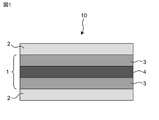
- FIG. 1 is a schematic cross-sectional view schematically showing a structure according to the first embodiment of the present disclosure.
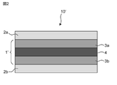
- FIG. 2 is a schematic cross-sectional view schematically showing a modification of the structure according to the first embodiment of the present disclosure.
- FIG. 3 is a schematic cross-sectional view schematically showing a structure according to the second embodiment of the present disclosure.
- FIG. 4 is a schematic cross-sectional view schematically showing a structure according to a third embodiment of the present disclosure;
- FIG. 5 is a schematic cross-sectional view schematically showing a structure according to a fourth embodiment of the present disclosure;
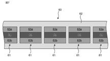
- FIG. 6 is a schematic cross-sectional view schematically showing a structure according to the fifth embodiment of the present disclosure.
- FIG. 1 is a schematic cross-sectional view schematically showing a structure according to the first embodiment of the present disclosure.
- FIG. 2 is a schematic cross-sectional view schematically showing a modification of the structure according to the first embodiment of the present disclosure.
- FIG. 3 is a
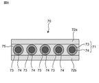
- FIG. 7 is a schematic cross-sectional view schematically showing a structure according to the sixth embodiment of the present disclosure.
- FIG. 8 is a schematic cross-sectional view schematically showing a structure according to the seventh embodiment of the present disclosure.
- FIG. 9 is a schematic diagram schematically showing a flexo-electret structure.
- FIG. 10 is a schematic diagram for schematically explaining the principle of the flexoelectric effect.
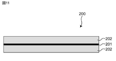
- FIG. 11 is a schematic cross-sectional view schematically showing a conventional polymer flexo-electret structure.
- 12 is a graph showing the electromotive force of the flexo electret structure measured in Example 1.
- cross-sectional view directly or indirectly described in this specification is based on, for example, a virtual cross section obtained by cutting the structure along the stacking direction of the layers that make up the structure.
- the "thickness” direction described herein, either directly or indirectly, is based on, for example, the stacking direction of the layers that make up the structure.
- Up-down direction and “left-right direction” used directly or indirectly in this specification correspond to the up-down direction and left-right direction in the drawing, respectively.
- the same reference numerals or symbols indicate the same members or parts or the same meanings.
- the stacking direction of the structure can correspond to the vertical direction
- the vertical downward direction that is, the direction in which gravity acts
- the opposite direction corresponds to the “bottom side”. It can be regarded as corresponding to "upward direction"/"top surface side”.
- FIG. 9 schematically shows how a “strain gradient” occurs in a conventional flexo-electret structure.
- the flexoelectric effect is a phenomenon that does not depend on the polarization treatment of the solid material product, and it is thought that the magnitude of the polarization due to the flexoelectric effect will be even greater when the polarization treatment is applied.
- ⁇ (flexoelectric coefficient) is a fourth-order tensor quantity and represents the constant of proportionality between the strain gradient and the polarization quantity.
- formula (I) can be represented by the following formula (II).
- formula (II) [Formula II] [Formula III]
- the flexoelectric effect in solid material products especially the flexoelectric effect due to bending, can be evaluated by the flexoelectric coefficient.
- the flexoelectric coefficient is 1.0 ⁇ 10 ⁇ 8 C/m.
- PVDF polyvinylidene fluoride
- a polymer flexo-electret formed by sandwiching a thin film 201 of charged polymer (e.g., polytetrafluoroethylene (PTFE)) that retains charge between two outer polymer (PTFE) thin films 202
- PTFE polytetrafluoroethylene
- the two outer polymer films 202 are pre-polarized by a charged polymer film 201, resulting in a flexoelectric coefficient approximately five times that of a normal polymer, specifically 5.3 ⁇ 10 ⁇ 8 C/m.
- the problem was that the flexoelectric effect was smaller than the piezoelectric effect.
- the problem was that the flexoelectric coefficient was small with respect to the piezoelectric constant.
- the flexoelectric coefficient due to the bending mode is proportional to the thickness of the entire flexo-electret structure and the charge density of the electret portion, as shown by the following formula (IV) (for example, Non-Patent Document 2). [Formula IV]
- the present inventors considered using a ceramic electret having a higher charge density than a polymer electret such as a charged polymer.
- a ceramic electret having a higher charge density than a polymer electret such as a charged polymer.
- the structure comprises a flexible member outside the electret portion, the electret portion being a ceramic electret comprising a ceramic component, a charge-retaining ceramic portion and an interior of the charge-retaining ceramic portion. and an internal electrode positioned in the electret portion having flexibility.
- Such structures of the present disclosure exhibit flexoelectric coefficients, flexoelectric effectiveness, durability such as weatherability, and loss of charge even when in contact with or immersed in liquids such as water and/or organic solvents. It is possible to obtain a structure having improved flexoelectric performance in at least one respect, such as being difficult to remove and maintaining the flexoelectric effect for a longer time (the effects described in this specification are only examples). and is not limited to, and may have additional effects).
- the present disclosure relates to structures with improved flexoelectric performance (hereinafter also referred to as “flexo-electret articles” or “flexo-electret structures”).
- flexoelectric performance particularly “improved flexoelectric performance” mainly means achieving a larger flexoelectric coefficient and a larger flexoelectric effect.
- durability such as weather resistance, and even when it is in contact with or immersed in liquid such as water and / or organic solvent, the electric charge is difficult to disappear, and the flexoelectric effect can be maintained for a long time. It may have performance such as
- the structure of the present disclosure is a structure capable of producing a flexoelectric effect. Therefore, the structure of the present disclosure can also be referred to as a "flexo electret body,” a “flexo electret product,” or a “flexo electret structure.”
- the "flexoelectric effect” means an electric polarization phenomenon that can occur in proportion to the spatial rate of change of the strain of the structure, that is, the "strain gradient" (see Fig. 9).
- the flexoelectric effect is a phenomenon that can occur in dielectrics, but it is an electric polarization phenomenon that is completely different from the piezoelectric effect that can occur in proportion to stress.
- the "flexoelectric coefficient" ( ⁇ ) is a fourth-order tensor quantity and means a constant of proportionality between the strain gradient and the polarization quantity.
- formula (I) can be represented by the following formula (II). [Formula II] [Formula III]
- bending mode means a system in which strain can occur in a structure when bending is applied to the structure, in other words, a system in which a bending moment can act on the structure.
- the flexoelectric effect in the present disclosure is not necessarily limited to the flexoelectric effect in bending mode.
- the “flexoelectric coefficient” of the flexo-electret structures of the present disclosure is, for example, approximately greater than 1.0 ⁇ 10 ⁇ 8 C/m, preferably greater than 1.3 ⁇ 10 ⁇ 8 C/m, and more Preferably greater than 5.0 ⁇ 10 ⁇ 8 C/m, even more preferably greater than 5.3 ⁇ 10 ⁇ 8 C/m. When the flexoelectric coefficient is within such a range, a greater flexoelectric effect can be achieved.
- the upper limit of the flexoelectric coefficient is not particularly limited, and is, for example, about 50 ⁇ 10 ⁇ 8 C/m, about 40 ⁇ 10 ⁇ 8 C/m, about 30 ⁇ 10 ⁇ 8 C/m, 20 ⁇ 10 ⁇ It may be on the order of 8 C/m, or on the order of 10 ⁇ 10 ⁇ 8 C/m.
- the shape of the flexo electret structure is not particularly limited.
- the flexo-electret structure may have any shape, such as plate-like or sheet-like (including strip-like), rod-like, or fiber-like (including fibers), and therefore its cross-sectional shape is not particularly limited. no.
- the cross-sectional shape of the flexo-electret structure may have any geometric shape, for example rectangular and/or circular.
- the flexo electret structure may have a shape and configuration that can be bent by an external force.
- the flexo-electret structure may be flexible. It is preferable that the flexo-electret structure has flexibility as a whole.
- the “flexibility” of a flexo-electret structure broadly refers to the ability of the structure (and structural components such as ceramic electrets and flexible members) to flex under external force. It means to bend or deform, preferably that the structure flexes without cracking and/or chipping. In a narrow sense, “flexibility” means that the structure bends at an arbitrary radius of curvature when the structure is bent, for example, as shown in FIG. bends at any radius of curvature (preferably without cracking and/or chipping).
- the flexo-electret structure When the flexo-electret structure receives a force from the outside and bends, for example, as shown in FIG. portion) may have a radius of curvature of approximately 5000 mm or less, e.g. It preferably has a radius of curvature of 1000 mm or less. That is, in a preferred aspect, when the structure of the present disclosure receives an external force and the electret portion is displaced, the electret portion has a radius of curvature of 1000 mm or less in a cross-sectional view. When the radius of curvature is within such a range, greater flexibility can be easily exhibited, and a greater flexoelectric effect can be brought about.
- the lower limit of the radius of curvature is not particularly limited, it may be, for example, about 500 mm, 600 mm, 700 mm, 800 mm, 900 mm, or 950 mm.
- the above radius of curvature is, for example, in a cross-sectional view or a side view of a structure obtained as an image such as an optical micrograph or an electron micrograph (for example, a cross-sectional view as typically shown in FIG. 9B), It may be based on the contour of the structure or its electret portion (particularly the contour of the main surface), and may be based on the contour portion of the contour where the bending is greatest.
- the "thickness" of the flexo electret structure is not particularly limited.
- the structure has a thickness that contributes to bending of the structure and that contributes to the above flexibility, particularly the above curvature radius.
- the overall thickness of the flexo-electret structure may be approximately 50 mm or less, 40 mm or less, 30 mm or less, 20 mm or less, for example 10 mm or less. Furthermore, the thickness of the entire flexo-electret structure may be 5 mm or less, such as 3 mm or less, 2.2 mm or less, or 2 mm or less (the lower limit of such a value is, for example, about 0.5 mm or 1 mm). may be). When the thickness of the structure is within such a range, a greater flexoelectric effect is likely to be produced.
- FIG. 1 shows the flexo electret structure of the present disclosure as a first embodiment.
- the structure shown in FIG. 1 is for explaining the concept of the flexo-electret structure of the present disclosure, and the illustrated contents are only schematically and exemplarily shown for understanding of the present invention. No.
- the structure (10) shown in FIG. 1 is a structure having an electret part (1).
- the structure (10) comprises a flexible member (2) on the outside of the electret part (1).
- the structure (10) comprises flexible members (2) on the outside corresponding to both sides of the electret part (1). It can also be said that the structure (10) has the electret part (1) inside the flexible member (2).
- Such an electret part (1) is a ceramic electret containing a ceramic component, and includes a charge retention ceramic part (3) and an internal electrode (4) located inside or inside the charge retention ceramic part (3). ), and the electret part (1) has flexibility.
- the electret part (1) provided as a ceramic electret containing a ceramic component has an internal electrode (4) and a charge retention ceramic part (3) outside thereof, and has flexibility as a whole. .
- the structure (10) of the present disclosure flexible members (2) are provided outside (preferably on both sides) of the flexible electret portion (1).
- two types of flexible members are provided so as to overlap each other or to be laminated.
- the structure of the present disclosure is It can exhibit flexibility.
- the structure (10) of the present disclosure is preferably bendable as a whole structure, preferably such that a bending moment is suitably induced. Bending the structure, for example as shown in FIG. 9, preferably induces a bending moment, resulting in a flexoelectric effect.
- the structure (10) is characterized in that the electret part (1) is a ceramic electret comprising a ceramic component, and that the electret part (1) is a charge retention ceramic part (3) and an internal electrode positioned therein. (4) is provided as one of the features.
- ceramic electrets can produce technical effects that are different from polymer electrets.
- the ceramic electret can have a higher charge density in the charge retaining ceramic portion (3) and a higher flexoelectric coefficient compared to conventional polymer electrets.
- structures of the present disclosure may provide greater flexoelectric effects (see formula (IV) below). Compared to conventional polymer electrets, it is possible to generate a larger voltage or electromotive force with the same amount of displacement.
- the flexible member (2) may have a thickness greater than the respective thicknesses of the internal electrode (4) and the charge retaining ceramic portion (3).
- the flexoelectric coefficient in the bending mode can be proportional to the "thickness" of the entire flexo-electret structure and the "charge density” of the electret portion, as shown in the following formula (IV). It can be understood. [Formula IV]
- the structure of the present disclosure by using a ceramic electret, durability such as weather resistance can be improved compared to conventional polymer electrets, and preferably such durability is improved more significantly.
- a ceramic electret even when it is brought into contact with or immersed in a liquid such as water and/or an organic solvent, the electric charge is less likely to disappear and the flexoelectric effect can be easily maintained for a longer period of time. Therefore, the structure of the present disclosure can be used favorably even in harsher environments, particularly outdoors or in higher temperature environments.
- the electret part (1) included in the structure (10) can be regarded as a dielectric, as will be described in detail below. Therefore, although not bound by a specific theory, the occurrence of electric polarization in the electret portion (1) suitably induces electric polarization in the flexible member (2) positioned outside the electret portion (1). This makes it easier to produce a greater flexoelectric effect, and can generate a greater voltage.
- the radius of curvature of the structure (10) in the bending mode is, for example, 1500 mm or less, 1300 mm or less, 1200 mm or less, or 1100 mm or less, preferably 1000 mm or less.
- the structure of the present disclosure can exhibit suitable flexibility even though it is a laminate containing ceramic elements, and can bring about a more suitable flexoelectric effect.
- the overall thickness of the structure (10) may be 0.1 mm to 10 mm or less, or such as 0.1 mm to 5 mm.
- the structure has a thickness relationship of flexible member (2)>internal electrode (4)>charge retaining ceramic portion (3). That is, the thickness of the flexible member (2) may be greater than the thickness of the internal electrode (4), and the thickness of the internal electrode (4) may be greater than the thickness of the charge retaining ceramic portion (3) (i.e. The thickness of the flexible member (2) may be greater than the thickness of the charge retaining ceramic portion (3)).
- the thickness of the charge retention ceramic portion (3) here refers to the thickness of the charge retention ceramic portion positioned either above or below the internal electrode (4) in a cross-sectional view of the structure. be.
- the thickness of the flexible member (2) also means the thickness of the flexible member positioned either above or below the internal electrode (4) in a cross-sectional view of the structure.
- the flexoelectric coefficient of the structure (10) is for example greater than 1.3 ⁇ 10 ⁇ 8 C/m, preferably greater than 5.0 ⁇ 10 ⁇ 8 C/m, more preferably 5.3 ⁇ Greater than 10 ⁇ 8 C/m (eg, greater than 5.5 ⁇ 10 ⁇ 8 C/m).
- a flexoelectric coefficient within such a range can provide greater flexoelectric effect to the structures of the present disclosure.
- the upper limit of the flexoelectric coefficient of the structure (10) is not particularly limited, and is 30 ⁇ 10 ⁇ 8 C/m, 20 ⁇ 10 ⁇ 8 C/m, 10 ⁇ 10 ⁇ 8 C/m, 9 ⁇ It may be 10 ⁇ 8 C/m, 8 ⁇ 10 ⁇ 8 C/m, etc. (the upper limit may include the value itself).
- the structure (10) may have a larger flexoelectric coefficient, and may have a unique flexoelectricity in that it is a ceramic electret that may at least have a favorable flexoelectric effect (preferably a more pronounced flexoelectric effect). It can be provided as a xo-electret structure.
- an “electret part” (1) is typically a part capable of carrying either positive or negative charge on its surface. Therefore, the electret portion can also be called a “charge holding portion”.
- the electret part (1) can polarize the surface of the flexible member (2) by carrying either positive or negative charge on its surface.
- the electret part (1) is a ceramic electret containing a ceramic component.
- a ceramic electret (1) comprises a charge-retaining ceramic portion (3) and an electrode located inside or inside the charge-retaining ceramic portion (3), ie, an internal electrode (4) (see FIG. 1). At least a ceramic component is included in the charge retention ceramic portion (3).
- the electret part (1) When the structure (10) receives an external force and the electret part (1) is displaced, especially when a bending moment acts (see FIG. 9), the electret part (1) has a radius of curvature of 5000 mm or less in cross section. and may have a radius of curvature of, for example, 4000 mm or less, 3000 mm or less, 2000 mm or less, 1500 mm or less, 1300 mm or less, 1200 mm or less, or 1100 mm or less, preferably 1000 mm or less.
- a radius of curvature of the electret part (1) within such a range means that a greater or better flexibility can be brought to the structure, thus a greater flexoelectric effect is produced in the structure. can be played in
- the lower limit of the radius of curvature is not particularly limited, but may be, for example, approximately 500 mm, 600 mm, 700 mm, 800 mm, 900 mm, or 950 mm.
- the ceramic electret located inside the flexible member may be thinner than the flexible member. That is, in a cross-sectional view of the structure, the thickness of the ceramic electret located inside the flexible member may be smaller than the thickness of the flexible member.
- the structure as a whole tends to exhibit suitable flexibility. That is, since the thickness of the ceramic electret positioned relatively inside is smaller than the thickness of the flexible member positioned relatively outside, the structure bends at an arbitrary radius of curvature when the structure is bent. (preferably able to bend without cracking and/or chipping) and the structure is more likely to have a suitable flexoelectric effect (preferably a more pronounced flexoelectric effect).
- ceramic electret means an electret comprising a “ceramic component” as detailed below.
- the ceramic electret does not necessarily have to consist entirely of ceramic components.
- the ceramic electret may be composed of a ceramic component and other components (for example, resin), or a partial region of the ceramic electret may be a non-semi-rack region.
- the "charge retaining ceramic portion” (3) is capable of retaining charge on its surface through dielectric polarization.
- the charge retaining ceramic portion (3) may be a material capable of producing dielectric polarization upon application of an electric field, ie a dielectric.
- dielectric polarization refers to a phenomenon in which charges in a dielectric are divided into positive and negative poles by the action of an external electric field.
- dielectric polarization may be used interchangeably with electrical polarization.
- the charge-retaining ceramic portion which is a member containing a ceramic component, may be provided with an electrode.
- the charge retaining ceramic part (3) has an internal electrode (4) inside or inside it, which can be used for earth connection or ground (GND) connection.
- GND earth connection
- the charge retaining ceramic portion (3) is electrostatically shielded by the ground, and the charge retaining ceramic portion (3) Only negative charges can be retained outside (3).
- only positive charges can be retained outside the charge retaining ceramic portion (3). In this way, when polarized by dielectric or electrical polarization, it can be charged to either a positive or negative polarity.
- the internal electrode (4) is interposed in the charge retention ceramic portion (3) so that the charge retention ceramic portion (3) and the internal electrode (4) are in contact with each other. It can be said that the internal electrode (4) is interposed so as to be sandwiched between the two members of the charge retention ceramic portion (3).
- the internal electrode (4) is positioned geometrically in the center of the charge retaining ceramic portion (3). For example, as shown in FIG. 1, the internal electrode (4) is arranged so that the internal electrode (4) exists in the middle position in the thickness direction (overall thickness) of the charge retention ceramic part (3). It may be positioned.
- the charge retention ceramic part (3) may have a plate-like or sheet-like shape. That is, the charge retention ceramic part (3) may have a form extending on the same plane.
- the charge-retaining ceramic part (3) may have a layered shape (preferably in the form of layers extending in the same plane or in the form of layers extending on a curved surface).
- the charge retention ceramic part (3) may have an elongated shape, for example, a strip shape (preferably an elongated strip shape).
- the charge-retaining ceramic portion (3) may have a fibrous shape (especially an elongated shape).
- the cross-sectional shape of the charge-retaining ceramic part (3) (for example, the outer contour in cross-section) may be square, rectangular, circular, or any other geometric shape.
- the charge retention ceramic part (3) has a circular contour or an elliptical contour (for example, a circular or elliptical outer contour) when viewed in cross section. good.
- the charge retaining ceramic part (3) has, for example, a tubular shape (see FIG. 8).
- the charge retention ceramic part (3) preferably has flexibility and/or softness.
- the thickness of the charge retention ceramic portion (3) may be 1 mm or less, for example, 0.005 mm or more and 1 mm or less, 0.005 mm or more and 0.05 mm or less. It may be 5 mm or less, 0.005 mm or more and 0.3 mm or less, or 0.01 mm or more and 0.1 mm or less.
- a charge retaining ceramic part (3) having such a thickness tends to exhibit suitable flexibility and/or softness.
- the "inner electrode” (4) has electrical conductivity.
- the internal electrodes contain at least a conductive material.
- the internal electrodes comprise a "metal” and/or a “conductive material” described below, and optionally other components.
- the internal electrode (4) is conductive, it can be used as an electrode of the electret for ground connection or ground (GND) connection.
- the charge retentive ceramic part (3) when the charge retentive ceramic part (3) is polarized by dielectric or electrical polarization, the charge retentive ceramic part (3), especially its surface, can be charged either positively or negatively.
- two members of the charge retaining ceramic part (3) provided outside the internal electrode (4) so as to form a pair i.e., the charge retaining ceramic located above the internal electrode (4)
- Both the member of the section (3) and the member of the charge retaining ceramic section (3) located below the internal electrode (4) are positively charged, or the charge retaining ceramic section (3) is Charge retention can be achieved in either way that both members are negatively charged.
- such a charge retaining ceramic part (3) can retain either charge, especially over its entire surface.
- the "metal” that can be contained in the internal electrode (4) may be a metal (for example, a single metal) or an alloy that can be composed of the metal elements described below.
- the metal or alloy that can be contained in the internal electrode (4) may be a sintered body.
- a simple metal made of a sintered body may be used in the internal electrode (4).
- the electrodes of the structure of the present disclosure ie, "internal electrodes" in the first embodiment
- the internal electrodes are sintered electrodes.
- the internal electrode is provided with a flexible member on the outer side, which preferably contributes to the flexibility and / or flexibility of the structure. It is a thing.
- the "sintered body” may generally be a sintered body (inorganic solid material body) obtained by heating and sintering an inorganic substance (for example, a paste of a composition containing an inorganic substance).
- the electrode (“internal electrode” in the first embodiment) of the structure of the present disclosure is formed by baking raw material powder (preferably inorganic powder such as metal raw material powder) or paste obtained therefrom by heat treatment. It may be a sintered body.
- Examples of “metals” that can be contained in the electrodes (“internal electrodes” in the first embodiment) in the structure of the present disclosure include gold (Au), silver (Ag), copper (Cu), iron (Fe), At least one selected from the group consisting of aluminum (Al), chromium (Cr), titanium (Ti), nickel (Ni), palladium (Pd) and platinum (Pt) can be used.
- the “conductive material” that can be included in the electrode (“internal electrode” in the first embodiment) in the structure of the present disclosure means a material having electrical conductivity, and if it has electrical conductivity There is no particular limitation on its specific type.
- Conductive material includes, for example, "conductive filler”.
- the conductive filler may be combined with a resin. That is, the conductive material that can be included in the electrodes (“internal electrodes” in the first embodiment) in the structure of the present disclosure may be a composite of conductive filler and resin. When the conductive material is provided as a composite, it tends to provide greater flexibility and/or softness to the internal electrode (4), which in turn tends to improve the flexibility of the ceramic electret and structure.
- Conductive filler means a material or substance that can impart conductivity (make it easier for electricity/electrons to pass) to a polymer material such as a resin, and if it can impart conductivity There is no particular limitation on its specific type. Examples include conductive fillers such as carbon-based, metal-based and/or metal oxide-based fillers. Examples of conductive fillers include carbon black, acetylene black, ketjen black, nanocarbon material, gold, silver, platinum, nickel, copper, zinc, aluminum, tin, manganese, stainless steel, tin oxide, indium oxide, zinc oxide, Conductive fillers comprising zinc oxide nickel, magnesium, tungsten, cobalt, chromium and/or titanium and the like.
- resin is meant, for example, a polymeric material.
- the specific type of resin is not particularly limited, and thermoplastic resin and/or thermosetting resin may be included in the electrodes (“internal electrodes” in the first embodiment) in the structure of the present disclosure.
- the resin may have a volume resistivity of 10 14 [ ⁇ m] or less (resistivity under temperature and humidity conditions of 23 ⁇ 5° C. and 50 ⁇ 20% relative humidity), for example.
- phenol resin epoxy resin, bismaleimide resin, vinyl chloride resin, urethane resin, nylon resin, ether resin, polyether resin, ketone resin, wholly aromatic polyester resin, polyamide resin, polyester resin, acrylic resin, polymethyl Resins such as methacrylate resins, melamine resins and/or silicone resins may be included in the electrodes (“internal electrodes” in the first embodiment) in the structure of the present disclosure.
- Composite in the present disclosure means a material in which two or more materials are combined, that is, a composite material.
- the composite may be a material in which the above-described "conductive filler” and “resin” are combined.
- the present disclosure is not necessarily limited to filler forms. That is, the electrodes (“internal electrodes” in the first embodiment) of the structure of the present disclosure preferably comprise a composite material, which comprises a metal component, an alloy component and/or a carbon component and a resin components.
- such a composite material may also be a mixture (or blend) in which two or more materials are simply mixed (or blended).
- the ratio of the conductive filler to the resin (conductive filler/resin) of the composite used for the electrode of the structure is, for example, 99/1 to 1/99, preferably 80/20 to 40/60 on a weight basis.
- the shape of the internal electrode (4) is not particularly limited, and may have a plate-like or sheet-like shape when more emphasis is placed on the charge density. That is, the internal electrodes (4) may have a form extending on the same plane. For example, the internal electrodes (4) may have a layered shape (preferably in the form of layers extending in the same plane or in the form of layers extending on curved surfaces). Similarly, when more emphasis is placed on the charge density, the internal electrode (4) may have an elongated shape, for example, a strip shape (preferably an elongated strip shape). Alternatively, if more emphasis is placed on flexibility and/or softness, the internal electrodes (4) may have a fibrous shape (especially an elongated shape).
- the cross-sectional shape of the internal electrode (4) (e.g. cross-sectional profile outside the view) may be square, rectangular or circular, or any other geometric shape.
- the internal electrode (4) preferably has flexibility and/or softness.
- the thickness of the internal electrode (4) thickness dimension when viewed in cross section
- the thickness of the internal electrode (4) is 2 mm or less, 1.5 mm or less, 1 mm or less, and 0.1 mm or less.
- a thickness of 0.05 mm or less for example, 0.005 mm or more and 2 mm or less, 0.005 mm or more and 1.5 mm or less, 0.01 mm or more and 1 mm or less, 0.01 mm or more and 0.5 mm or less, 0.01 mm or more and 0.5 mm or less. It may be 01 mm to 0.3 mm, 0.01 mm to 0.1 mm, or 0.01 mm to 0.05 mm.
- An internal electrode (4) having such a thickness tends to exhibit suitable flexibility and/or softness.
- the thickness of the internal electrode (4) may be greater than the thickness of the charge retention ceramic portion (3).
- the internal electrode (4) may be a member that supports the charge retention ceramic portion (3). Therefore, the internal electrode (4) makes it easier to increase the strength of the ceramic electret, which in turn makes it easier to increase the strength of the electret (1). Also, the internal electrode (4) may function as a shield. In such a case, the internal electrode (4) can serve as a shield member.
- the internal electrodes (4) contain metal and/or conductive fillers and contribute to electrical connection with the outside.
- the internal electrode (4) is connected to the ground or GND, so that the charge retention ceramic part (3) ) (preferably over the surface of the charge-retentive ceramic portion (3), more preferably over its entire surface), either positive or negative surface potential can be provided.
- the internal electrode (4) thus preferably prevents the two charge-retaining ceramic parts (3), for example shown in FIG. xoelectric effect) can be brought to the structure.
- flexible member (2) means a member having at least flexibility.
- the flexible member (2) may be a member capable of being polarized by the electret portion (1) described above, in particular the charged charge retaining ceramic portion (3).
- the flexible member (2) preferably contains a resin component.
- the resin component may be the component with the highest content (in such a case, the flexible member is particularly referred to as a "resin member” or a “flexible resin member”). can also be called).
- the resin component By including the resin component in the flexible member (2), it becomes easier to impart more suitable flexibility and chargeability to the structure.
- the resin that can be contained in the flexible member (2) may be a polymeric material.
- thermoplastic resins and/or thermosetting resins may be included in the flexible members of the structure.
- More specific resin components of the flexible member include, for example, phenol resin, epoxy resin, bismaleimide resin, vinyl chloride resin, urethane resin, nylon resin, ether resin, polyether resin, ketone resin, and wholly aromatic resin.
- polyester resins, polyamide resins, polyester resins, acrylic resins, polymethyl methacrylate resins, melamine resins, silicone resins, fluorine-based resins (e.g. polyvinylidene fluoride (PVDF) and/or polytetrafluoroethylene (PTFE)), etc. can be done.
- the thickness of the flexible member (2) may be 10 mm or less, or 5 mm or less, for example, 0.05 mm or more and 10 mm or less, 0.05 mm or more and 8 mm or less, The thickness may be 0.1 mm or more and 5 mm or less, 0.5 mm or more and 5 mm or less, 0.5 mm or more and 4 mm or less, 0.5 mm or more and 3 mm or less, or 0.5 mm or more and 2 mm or less.
- the thickness of the flexible member (2) is easily deformed following the electret portion (1), resulting in more suitable flexibility and/or softness. It becomes easier for the structure to have properties.
- the thickness of the flexible member (2) is the same as that of the internal electrode (4). It is preferably larger than the thickness.
- the thickness of the flexible member (2) is within the above range, it becomes easy to provide the flexible member as a member having a thickness relatively larger than that of the electret portion (1). The amount of deformation or displacement can be made larger than that of the electret portion (1). Therefore, a more suitable flexoelectric effect (for example, a larger flexoelectric effect) is likely to be brought about to the structure.
- the electrets of the structures of the present disclosure include ceramic components.
- the ceramic component is included in the charge-retaining ceramic portion provided in the ceramic electret of the structure.
- ceramic component means an inorganic compound component (oxide, carbide and/or nitride) containing metallic elements.
- the ceramic component may correspond to a sintered body (inorganic solid material body) obtained by heating and sintering an inorganic material (preferably a paste of a composition containing an inorganic material) as a raw material thereof.
- a ceramic component of a ceramic electret may be a component that can be used as a ceramic-based biomaterial.
- apatite which has biocompatibility as a biomaterial and has high mechanical strength, fracture toughness, and excellent electronic properties, may be used in the structure of the present disclosure (particularly, its ceramic electret). In such cases, apatite can be unique in that it is used in fields such as electrets, even though it is a ceramic known as a biomaterial.
- Apatite is a ceramic known as a calcium phosphate-based functional inorganic material, typically containing phosphorus (P) and calcium (Ca) as main components.
- Apatite generally has high mechanical strength and fracture toughness, and is excellent in electronic physical properties, biocompatibility, ion exchange properties, surface adsorption properties, optical properties, and the like.
- the use of such materials in the ceramic electret facilitates imparting high mechanical strength and fracture toughness to the electret portion (1), as well as flexibility and/or charge-holding ability. It becomes easier to give electronic physical properties such as the expression and control of
- Apatite is preferably at least one selected from the group consisting of fluoroapatite, chloroapatite and hydroxyapatite. Among them, it is particularly preferable to use hydroxyapatite. Although hydroxyapatite is a ceramic known as a biomaterial, it can offer peculiarities in that it is used in fields such as electrets. Hydroxyapatite can provide the structure of the present disclosure with excellent electronic properties such as charge retention ability as well as high mechanical strength and fracture toughness.
- Fluorapatite (FAp) (fluorapatite) is not limited to its specific type.
- fluoroapatite may be represented by the chemical formula: Ca 5 (PO 4 ) 3 F, although there is no particular limitation.
- a fluoroapatite called “fluoroapatite” or “fluoroapatite” may be used.
- Chlorapatite (CAp) (chlorapatite) is not limited to its specific type.
- chloroapatite may be represented by the chemical formula: Ca 5 (PO 4 ) 3 Cl, although there is no particular limitation.
- Chloroapatite also called “chlorapatite”, “chlorapatite” may be used
- hydroxyapatite (HAp) (hydroxyapatite) is not limited to its specific type.
- hydroxyapatite may be represented by the chemical formula: Ca 5 (PO 4 ) 3 OH, although there is no particular limitation.
- Hydroxyapatite also called “hydroxyapatite”, “hydroxyapatite” may be used.
- the "ceramic component” in the present disclosure is not particularly limited as long as it is a component (element) that can form ceramics (ceramic crystals, especially metal oxides).
- a component element
- metal oxides For example, lithium (Li), sodium (Na), potassium (K), magnesium (Mg), calcium (Ca), strontium (Sr), barium (Ba), yttrium (Y), zirconium (Zr), titanium (Ti ), vanadium (V), chromium (Cr), manganese (Mn), iron (Fe), cobalt (Co), nickel (Ni), copper (Cu), zinc (Zn), boron (B), aluminum (Al ), silicon (Si), indium (In), tin (Sn), antimony (Sb), barium (Ba), tantalum (Ta), tungsten (W), lead (Pb), bismuth (Bi), lanthanum (La ), Cesium (Ce), Neodymium (Nd), Samarium
- a glass component may be included as a ceramic component of the ceramic electret.
- glass components include soda lime glass, potash glass, borate-based glass, borosilicate-based glass, barium borosilicate-based glass, zinc borate-based glass, barium borate-based glass, and bismuth borosilicate-based glass. , bismuth zinc borate glass, bismuth silicate glass, phosphate glass, aluminophosphate glass and zinc phosphate glass.
- the ceramic component may include grains or crystallites.
- the components of the ceramic electret are lead zirconate titanate (PZT), barium titanate (BaTiO 3 ) (BT), bismuth sodium titanate ((Bi 1/2 Na 1/2 )TiO 3 ) (BNT), It may be zirconia, yttrium-stabilized zirconia, or glass, and grains or crystallites containing such components may be included in the ceramic electret.
- the "charge retaining ceramic portion” (3) is a portion or member containing the above ceramic component. Therefore, the charge retention ceramic portion (3) may be composed of the above ceramic component, or may be a composite composed of the above ceramic component and other components such as resin. When the charge retentive ceramic part (3) comprises a composite, it is easier to impart flexibility and/or flexibility to the charge retentive ceramic part (3), thus making the ceramic electret and structure more flexible. becomes easier.
- composite means two or more kinds of materials.
- charge retention ceramic part (3) at least a “ceramic component” and “another component” are compounded (composite material). material).
- the composite used for the charge retention ceramic portion (3) may be a mixture (or compound) in which two or more materials are simply mixed (or compounded).
- the "resin” provided as another component of the composite used for the charge retention ceramic part (3) may be a polymer material.
- the type of resin as long as it is a polymeric material, and thermoplastic resin and/or thermosetting resin may be included in the charge retention ceramic portion.
- the charge retention ceramic portion may include resin components such as phenolic resin, epoxy resin, bismaleimide resin, polypropylene resin, polyimide resin, polyamideimide resin, and/or acrylonitrile resin.
- the ratio (ceramic component/resin) of the ceramic component of the composite contained in the charge retention ceramic portion to the resin is, on a volume basis, for example, 99/1 to 1/99, preferably 64/36 to 1/99, more preferably 64/36 to 1/99. It is in the range of 30/70 to 1/99, even more preferably 20/80 to 1/99.
- the electret part (1) which is provided as a ceramic electret containing a ceramic component, is composed of a charge-retaining ceramic part (3) and an internal electrode (4). It is easy to improve (preferably significantly improve) the strength and/or charge density of the structure.
- a flexible member (2) is provided outside the electret portion (1). More preferably, flexible members (2) are provided so as to sandwich or surround the electret portion (1).
- flexible members (2) may be provided at positions facing each other in contact with the electret portion (1) (for example, a first flexible member provided as two members as shown in FIG. 1). Both the elastic member and the second flexible member may be provided so as to face each other while being in contact with the outer main surface of the electret portion (1)).
- the electret part (1) in the present disclosure is easily positioned at the center of the flexo-electret structure (10).
- the electret part (1) can be a member that is relatively difficult to deform with respect to the flexible member (2), while the flexible member (2) is relatively deformable with respect to the electret part (1).
- the electret part (1) can have a relatively high Young's modulus (eg, apparent Young's modulus) with respect to the flexible member (2), while the flexible member (2) may have a relatively low Young's modulus (eg, apparent Young's modulus) relative to the electret portion (1).
- Young's modulus eg, apparent Young's modulus
- Young's modulus eg, apparent Young's modulus
- the flexible member (2) can be displaced large (preferably selectively large displacement), and a larger strain gradient is applied to the flexible member (2). easily brought about.
- the structure of the present disclosure can exhibit a more suitable (preferably more pronounced) flexoelectric effect, and can achieve a larger electromotive force (increased power generation, increased sensor sensitivity, etc.). can be done).
- conventional polymer flexo-electrets may have a uniform Young's modulus, which may differ from the flexoelectric expression described above.
- the flexo-electret structure (10) of the present disclosure comprises an electret portion (1), in particular a charge retentive ceramic portion (3), and a flexible member (2) covering the charge retentive ceramic portion (3).
- the flexible member (2) can effectively protect the charge retention ceramic portion (3) from water and/or organic solvents. In other words, the flexible member (2) can act as a protective layer.
- the structure (10) of the present disclosure can exhibit more suitable durability such as weather resistance (preferably more improved durability such as weather resistance) compared to conventional polymer electrets, In addition, it can be used in more severe high-temperature environments (for example, in cars, etc.) including outdoors.
- FIG. 2 shows a structure 10' as a modification of the structure according to the first embodiment.
- Structure 10' may basically correspond to structure 10 shown in FIG.
- An electret portion 1' that may be included in the structure 10' shown in FIG. 2 may correspond to the electret portion 1 of the structure 10 shown in FIG.
- the modification of FIG. 2 corresponds to an aspect in which the constituent elements of the structure are composed of sub-members.
- the charge retentive ceramic portion is composed of a plurality of sub-members.
- the charge retention ceramic portion 3 included in the electret portion 1 is composed of at least a first charge retention ceramic layer 3a and a second charge retention ceramic layer 3b
- An internal electrode 4 is positioned between the first charge-retaining ceramic layer 3a and the second charge-retaining ceramic layer 3b, as in the structure 10 shown in FIG.
- the first charge-retaining ceramic layer 3a and the second charge-retaining ceramic layer 3b can be configured similarly to the charge-retaining ceramic layer 3 included in the electret portion 1 of the structure 10 shown in FIG.
- the first charge retention ceramic layer 3a and the second charge retention ceramic layer 3b may be made of the same material.
- the first charge retention ceramic layer 3a and the second charge retention ceramic layer 3b may be made of different materials.
- the internal electrode 4 is positioned between the first charge-retaining ceramic layer 3a and the second charge-retaining ceramic layer 3b, the first charge-retaining ceramic layer 3a and the second charge-retaining ceramic layer 3b 3b can be charged with either positive or negative charges, especially at its surface, which can lead to a better (preferably more pronounced) electrical effect.
- the surfaces of the first charge-retaining ceramic layer 3a and the second charge-retaining ceramic layer 3b can both have charges of the same sign (+ or -), and at least in that respect have a more favorable electrical effect (preferably more noticeable electrical effects) can be produced.
- the thickness of the first charge retaining ceramic layer 3a and the thickness of the second charge retaining ceramic layer 3b may be the same.
- the thicknesses of the first charge-retaining ceramic layer 3a and the second charge-retaining ceramic layer 3b may be different from each other.
- the Young's modulus eg., apparent Young's modulus
- the strength of the structure is likely to be improved together with the flexible member.
- the flexible member 2 is also made up of a plurality of sub-members. More specifically, in the structure 10' shown in FIG. 2, the flexible member 2 is composed of at least a first flexible member 2a and a second flexible member 2b. An electret portion 1' is positioned between the member 2a and the second flexible member 2b.
- the first flexible member 2a and the second flexible member 2b may be made of the same material. Alternatively, the first flexible member 2a and the second flexible member 2b may be made of different materials.
- the first flexible member 2a and the second flexible member 2b in FIG. 2 can be configured in the same manner as the flexible member 2 included in the structure 10 shown in FIG. can.
- the thicknesses of the first flexible member 2a and the second flexible member 2b in the structure 10' may be the same. Alternatively, the thicknesses of the first flexible member 2a and the second flexible member 2b may differ from each other.
- Each of the elastic members 2b may have a plate-like or sheet-like shape.
- each of these members may have a form such that each extends on the same plane.
- the structure 10' as a laminated body formed by laminating the first charge-retaining ceramic layer 3a, the second charge-retaining ceramic layer 3b, the internal electrode 4, the first flexible member 2a, and the second flexible member 2b. may be provided.
- the first charge-retaining ceramic layer 3a, the second charge-retaining ceramic layer 3b, the internal electrode 4, the first flexible member 2a, and the second flexible member 2b may have an elongated shape, such as a strip shape. (particularly elongate strips). With such a shape, the structure 10′ shown in FIG. 2 tends to take a plate-like or sheet-like shape as a whole, and a more suitable electric effect (preferably a more pronounced electric effect) is produced due to the higher charge density. easier to bring.
- FIG. 3 shows a structure 20 according to the second embodiment.
- Structure 20 may basically correspond to structure 10 shown in FIG.
- the electret part 21 included in the structure 20 shown in FIG. 3 can correspond to the electret part 1 of the structure 10 shown in FIG.
- the second embodiment corresponds to a mode in which the constituent elements of the structure are composed of sub-members, and the flexible member is composed of a resin member.
- An internal electrode 24 is positioned between the first charge retaining ceramic layer 23a and the second charge retaining ceramic layer 23b.
- the first charge-retaining ceramic layer 23a and the second charge-retaining ceramic layer 23b can be configured similarly to the charge-retaining ceramic portion 3 of the structure 10 shown in FIG.
- the first charge retention ceramic layer 23a and the second charge retention ceramic layer 23b may be made of the same or different materials, as in the structure described above.
- the thicknesses of the first charge-retaining ceramic layer 23a and the second charge-retaining ceramic layer 23b may be the same or different.
- the internal electrodes 24 shown in FIG. 3 can also be configured in the same manner as the internal electrodes 4 of the structure 10 shown in FIG.
- the flexible member is composed of at least the first resin layer 22a and the second resin layer 22b, and the electret portion is formed between the first resin layer 22a and the second resin layer 22b. 21 are positioned. Since the first resin layer 22a and the second resin layer 22b can have a relatively lower Young's modulus than the electret portion 21, they are easily displaced greatly (preferably, they are easily displaced largely selectively), and have a larger strain gradient. can occur. Therefore, the electromotive force generated in the structure 20 tends to increase.
- the first resin layer 22a and the second resin layer 22b may each be a layer containing the above resin component. That is, each of the first resin layer 22a and the second resin layer 22b may be a member made of the above resin component.
- the first resin layer 22a and the second resin layer 22b may be made of the same material.
- the first resin layer 22a and the second resin layer 22b may be made of different materials.
- the thickness of the first resin layer 22a and the thickness of the second resin layer 22b may be the same.
- the thicknesses of the first resin layer 22a and the second resin layer 22b may be different from each other.
- the first charge retention ceramic layer 23a, the second charge retention ceramic layer 23b, the internal electrode 24, the first resin layer 22a, and the second resin layer 22b included in the electret portion 21 are each , plate-like or sheet-like shape.
- each of these members may have a form such that each extends on the same plane.
- the structure 20 is provided as a laminate formed by stacking the first charge retention ceramic layer 23a, the second charge retention ceramic layer 23b, the internal electrode 24, the first resin layer 22a and the second resin layer 22b. good.
- the first charge retention ceramic layer 23a, the second charge retention ceramic layer 23b, the internal electrode 24, the first resin layer 22a, and the second resin layer 22b may have an elongated shape, such as a strip shape (especially an elongated strip). shape). With such a shape, the structure 20 shown in FIG. 3 tends to take a plate-like or sheet-like shape as a whole, and a higher electric charge density results in a more suitable electric effect (preferably a more pronounced electric effect). ) is more likely to occur.
- FIG. 4 shows a structure 30 according to the third embodiment.
- Structure 30 may basically correspond to structure 20 shown in FIG.
- the electret portion 31 included in the structure 30 shown in FIG. 4 can correspond to the electret portion 21 of the structure 20 shown in FIG.
- the third embodiment corresponds to a mode in which the constituent elements of the structure are composed of sub-members, the flexible member is composed of a resin member, and external electrodes are additionally provided.
- the electret portion 31 includes at least a first charge-retaining ceramic layer 33a and a second charge-retaining ceramic layer 33b, and an internal electrode 34 is provided between the first charge-retaining ceramic layer 33a and the second charge-retaining ceramic layer 33b. positioned.
- the first charge-retaining ceramic layer 33a and the second charge-retaining ceramic layer 33b can be configured similarly to the first charge-retaining ceramic layer 23a and the second charge-retaining ceramic layer 23b, respectively, of the structure 20 shown in FIG. .
- the first charge-retaining ceramic layer 33a and the second charge-retaining ceramic layer 33b may be made of the same or different materials as in the structure described above.
- the thicknesses of the first charge-retaining ceramic layer 33a and the second charge-retaining ceramic layer 33b may be the same or different.
- the internal electrodes 34 shown in FIG. 4 can be configured similarly to the internal electrodes 24 of the structure 20 shown in FIG.
- the structure 30 shown in FIG. 4 includes a first resin layer 32a and a second resin layer 32b, and the electret portion 31 is positioned between the first resin layer 32a and the second resin layer 32b.
- the first resin layer 32a and the second resin layer 32b can be configured similarly to the first resin layer 22a and the second resin layer 22b of the structure 20 shown in FIG. 3, respectively.
- the first resin layer 32a and the second resin layer 32b may be made of the same material or may be made of different materials. Also, the thicknesses of the first resin layer 32a and the second resin layer 32b may be the same or different.
- the structure 30 according to the third embodiment shown in FIG. 4 includes the first external electrodes 5a on at least part of the outer surface of the first resin layer 32a, and the outer surface of the second resin layer 32b.
- a second external electrode 5b is provided.
- the first external electrode 5a and the second external electrode 5b may be electrodes for extracting charges generated by the flexoelectric effect in the structure 30 or for measuring the generated potential.
- the material of the first external electrode 5a and the second external electrode 5b is a conductive resin (for example, a volume resistivity of 10 14 [ ⁇ m] or less (at a temperature of 23 ⁇ 5° C. and a relative humidity of 50 ⁇ 20%). resistivity under humidity conditions).
- the conductive resin may be a thermoplastic resin and/or a thermosetting resin, etc.
- the material of the first external electrode 5a and the second external electrode 5b is , a composite of a conductive filler and a resin, in which case the conductive filler is carbon black, acetylene black, ketjen black, nanocarbon materials, gold, silver, platinum, nickel, copper, zinc,
- the filler may include components such as aluminium, tin, manganese, stainless steel, tin oxide, indium oxide, zinc oxide, zinc nickel oxide, magnesium, tungsten, cobalt, chromium and/or titanium, etc.
- the resin is, for example, a phenolic resin.
- first external electrode 5a and the second external electrode 5b epoxy resin, bismaleimide resin, vinyl chloride resin, urethane resin, nylon resin, ether resin, polyether resin, ketone resin, wholly aromatic polyester resin, polyamide resin, polyester resin, acrylic resin, polymethyl methacrylate resin, melamine resin and/or silicone resin).
- a conventionally known electrode material may be used for the first external electrode 5a and the second external electrode 5b.
- the first external electrode 5a and the second external electrode 5b may be made of at least one metal element selected from the group consisting of:
- the first external electrode 5a and the second external electrode 5b may be composed of a metal oxide film such as ITO.
- the shapes of the first external electrode 5a and the second external electrode 5b are not particularly limited, and may be plate-like, for example.
- the first external electrode 5a and the second external electrode 5b have a thin film-like or sheet-like shape.
- the first external electrode 5a may be arranged on at least part of or the entire outer surface of the first resin layer 32a, and is preferably arranged at the geometric center of the outer surface of the first resin layer 32a.
- the second external electrode 5b may be arranged on at least part of or the entire outer surface of the second resin layer 32b, and is preferably arranged at the geometric center of the outer surface of the second resin layer 32b.
- each of the first external electrode 5a and the second external electrode 5b is, for example, 1 nm or more and 0.01 mm or less. When the thickness is within the above range, it becomes easy to successfully take out the electric charge while ensuring the flexibility of the structure.
- the thickness of the first external electrode 5a and the second external electrode 5b may be smaller than the thickness of the first resin layer 32a and the second resin layer 32b. In a preferred embodiment, the thicknesses of the first external electrode 5a and the second external electrode 5b are equal to the thicknesses of the first charge retaining ceramic layer 33a, the second charge retaining ceramic layer 33b, the internal electrode 34, the first resin layer 32a and the second external electrode 5b. It is smaller than the thickness of any one, any two, any three, any four, or all of the resin layers 32b.
- Each of the first external electrode 5a and the second external electrode 5b preferably has a plate-like or sheet-like shape.
- each of these members may have a form such that each extends on the same plane. Lamination in which the first charge retention ceramic layer 33a, the second charge retention ceramic layer 33b, the internal electrode 34, the first resin layer 32a, the second resin layer 32b, the first external electrode 5a, and the second external electrode 5b are laminated together
- a structure 30 may be provided as the body.
- the first charge retention ceramic layer 33a, the second charge retention ceramic layer 33b, the internal electrode 34, the first resin layer 32a, the second resin layer 32b, the first external electrode 5a and the second external electrode 5b have elongated shapes.
- it may have a strip shape (especially an elongated strip shape).
- the structure 30 shown in FIG. 4 tends to take a plate-like or sheet-like shape as a whole, and a higher electric charge density results in a more suitable electric effect (preferably a more pronounced electric effect). ) is more likely to occur.
- FIG. 5 shows a structure 40 according to a fourth embodiment.
- Structure 40 may basically correspond to structure 30 shown in FIG.
- the electret portion 41 included in the structure 40 shown in FIG. 5 can correspond to the electret portion 31 of the structure 30 shown in FIG.
- the fourth embodiment particularly corresponds to a mode in which a polarization electrode is provided as an auxiliary electrode.
- the electret portion 41 includes at least a first charge-retaining ceramic layer 43a and a second charge-retaining ceramic layer 43b, and an internal electrode 44 is interposed between the first charge-retaining ceramic layer 43a and the second charge-retaining ceramic layer 43b. positioned.
- the first charge-retaining ceramic layer 43a and the second charge-retaining ceramic layer 43b can be configured similarly to the first charge-retaining ceramic layer 33a and the second charge-retaining ceramic layer 33b, respectively, of the structure 30 shown in FIG. .
- the first charge retention ceramic layer 43a and the second charge retention ceramic layer 43b may be made of the same material or different materials, as in the structure described above.
- the thicknesses of the first charge-retaining ceramic layer 43a and the second charge-retaining ceramic layer 43b may be the same or different.
- the internal electrodes 44 shown in FIG. 5 can be configured similarly to the internal electrodes 34 of the structure 30 shown in FIG.
- the structure 40 includes a first resin layer 42a and a second resin layer 42b, and between the first resin layer 42a and the second resin layer 42b, an electret portion 41 is formed by a first polarization electrode, which will be described in detail below. 6a and a second polarizing electrode 6b.
- the first resin layer 42a and the second resin layer 42b can be configured similarly to the first resin layer 32a and the second resin layer 32b of the structure 30 shown in FIG. 4, respectively.
- the first resin layer 42a and the second resin layer 42b may be made of the same material or different materials.
- the thicknesses of the first resin layer 42a and the second resin layer 42b may be the same or different.
- the structure 40 shown in FIG. 5 includes a first external electrode 45a on at least part of the outer surface of the first resin layer 42a, and a second external electrode 45b on at least part of the outer surface of the second resin layer 42b.
- the first external electrode 45a and the second external electrode 45b can be configured similarly to the first external electrode 5a and the second external electrode 5b of the structure 30 shown in FIG. 4, respectively.
- the first external electrode 45a and the second external electrode 45b may be made of the same material or may be made of different materials.
- the thickness of the first external electrode 45a and the thickness of the second external electrode 45b may be the same or different.
- the structure 40 shown in FIG. 5 includes electrodes for polarization. Specifically, a polarization electrode is further provided between the resin layer and the electret portion.
- the first polarization electrode is interposed between the first resin layer 42a and the electret portion 41 (more specifically, between the first resin layer 42a and the first charge retention ceramic layer 43a). 6a, and a second polarization electrode 6b between the second resin layer 42b and the electret portion 41 (more specifically, between the second resin layer 42b and the second charge retention ceramic layer 43b).
- the first polarization electrode 6a and the second polarization electrode 6b are electrodes for dielectrically or electrically polarizing the first charge retention ceramic layer 43a and the second charge retention ceramic layer 43b, respectively, in the structure 40. good.
- the charge retention ceramic layer 43a and the second charge retention ceramic layer 43b can be easily dielectrically polarized or electrically polarized after the structure 40 is manufactured. Become.
- the material of the first polarization electrode 6a and the second polarization electrode 6b is a conductive resin (for example, a volume resistivity of 10 14 [ ⁇ m] or less (at a temperature of 23 ⁇ 5° C. and a relative humidity of 50 ⁇ 20%).
- the conductive resin may be a thermoplastic resin and/or a thermosetting resin.
- the first polarizing electrode 6a and the second polarizing electrode 6b The material may be a composite of conductive filler and resin, in which case the conductive filler may be carbon black, acetylene black, ketjen black, nano carbon material, gold, silver, platinum, nickel, copper, Fillers may include components such as zinc, aluminum, tin, manganese, stainless steel, tin oxide, indium oxide, zinc oxide, zinc nickel oxide, magnesium, tungsten, cobalt, chromium and/or titanium.
- Phenol resin epoxy resin, bismaleimide resin, vinyl chloride resin, urethane resin, nylon resin, ether resin, polyether resin, ketone resin, wholly aromatic polyester resin, polyamide resin, polyester resin, acrylic resin, polymethyl methacrylate resin , melamine resins and/or silicone resins).
- Conventionally known electrode materials may be used for the first polarization electrode 6a and the second polarization electrode 6b.
- the first polarizing electrode 6a and the second polarizing electrode 6b may be made of at least one metal element selected from the group consisting of:
- the first polarization electrode 6a and the second polarization electrode 6b may be metal oxide films such as ITO.
- first polarization electrode 6a and the second polarization electrode 6b may be plate-shaped.
- first polarizing electrode 6a and the second polarizing electrode 6b have a thin film-like or sheet-like shape.
- the first polarization electrode 6a may be arranged on at least part of or the entire surface of the first charge retention ceramic layer 43a.
- the second polarization electrode 6b may be arranged on at least part of or the entire surface of the second charge retention ceramic layer 43b.
- the thicknesses of the first polarization electrode 6a and the second polarization electrode 6b are, for example, 1 nm or more and 0.01 mm or less. When the thickness is within the above range, the charge retention ceramic layer 43a and the second charge retention ceramic layer 43b can be easily dielectrically or electrically polarized while providing flexibility to the structure.
- the first external electrode 45a, the second external electrode 45b, the first polarization electrode 6a, and the second polarization electrode 6a may each have a plate-like or sheet-like shape.
- each of these members may have a form such that each extends on the same plane.
- the structure 40 may be provided as a stack of the second polarizing electrode 6a and the second polarizing electrode 6a stacked on top of each other.
- First charge retention ceramic layer 43a, second charge retention ceramic layer 43b, internal electrode 44, first resin layer 42a, second resin layer 42b, first external electrode 45a, second external electrode 45b, first polarization electrode 6a and the second polarizing electrode 6a may have an elongated shape, for example, a strip shape (especially an elongated strip shape). With such a shape, the structure 40 shown in FIG. 5 tends to take a plate-like or sheet-like shape as a whole, and a higher electric charge density results in a more suitable electric effect (preferably a more pronounced electric effect). ) is more likely to occur.
- FIG. 6 shows a structure 50 according to the fifth embodiment.
- Structure 50 may basically correspond to structure 20 shown in FIG.
- the electret portion 51 that can be included in the structure 50 shown in FIG. 6 can correspond to the electret portion 21 of the structure 20 shown in FIG.
- the electret portion 51 includes at least a first charge-retaining ceramic layer 53a and a second charge-retaining ceramic layer 53b, and an internal electrode 54 is provided between the first charge-retaining ceramic layer 53a and the second charge-retaining ceramic layer 53b. positioned.
- the first charge-retaining ceramic layer 53a and the second charge-retaining ceramic layer 53b can be configured similarly to the first charge-retaining ceramic layer 23a and the second charge-retaining ceramic layer 23b, respectively, of the structure 20 shown in FIG. .
- the materials of the first charge retention ceramic layer 53a and the second charge retention ceramic layer 53b may be the same or different. good.
- the thickness of the first charge retention ceramic layer 53a and the second charge retention ceramic layer 53b may be the same or different.
- the electret portion is provided inside the flexible member.
- the electret portion 51 is positioned inside the resin member or resin layer 52 .
- the flexible member is provided so as to surround the electret portion. A part of the electret part 51 may not be covered with the resin member or the resin layer 52, and a part of the electret part 51 may be exposed.
- the resin member or resin layer 52 may contain the above resin component. That is, the resin layer 52 may be a surrounding member made of the above resin component.
- the thickness of the resin member or resin layer 52 is, for example, 0.03 mm or more and 10 mm or less. Resin member or resin layer 52 may or may not be uniform. When the thickness of the resin member or resin layer 52 is within the above range, a more suitable electric effect (preferably a more remarkable electric effect) is likely to be brought about to the structure 50 .
- external electrodes may be provided on at least part of the outer surface of the resin layer 52 (see the external electrodes 45a and 45b shown in FIG. 5), as in the embodiment shown in FIG. matter).
- a polarization electrode may be provided between the resin layer 52 and the electret portion 51, specifically between the resin layer 52 and the charge retention ceramic layers (53a, 53b) (the polarization electrode 6a shown in FIG. 5). , 6b).
- FIG. 7 shows a structure 60 according to the sixth embodiment.
- the structural body 60 can basically correspond to the structural body 50 shown in FIG.
- the number of electret portions 61 is not particularly limited.
- the plurality of electret portions 61 may be the same or different.
- the electret portion 61 includes at least a first charge-retaining ceramic layer 63a and a second charge-retaining ceramic layer 63b, and an internal electrode 64 is interposed between the first charge-retaining ceramic layer 63a and the second charge-retaining ceramic layer 63b. positioned.
- the first charge-retaining ceramic layer 63a and the second charge-retaining ceramic layer 63b can be configured similarly to the first charge-retaining ceramic layer 53a and the second charge-retaining ceramic layer 53b, respectively, of the structure 50 shown in FIG. .
- the internal electrodes 64 shown in FIG. 7 can be formed using the same material as the internal electrodes 54 shown in FIG.
- the resin member or resin layer 62 shown in FIG. 7 may comprise the resin component described above. That is, the resin layer 62 may be a surrounding member made of the above resin component.
- external electrodes may be provided on at least part of the outer surface of the resin layer 62 (see the external electrodes 45a and 45b shown in FIG. 5), as in the embodiment shown in FIG. matter).
- Polarizing electrodes may be provided between the resin layer 62 and the electret portion 61 shown in FIG. 7, specifically between the resin layer 62 and the charge retention ceramic layers (63a, 63b) (shown in FIG. 5). see polarizing electrodes 6a, 6b).
- FIG. 8 shows a structure 70 according to the seventh embodiment.
- the structure 70 can basically correspond to the structure 10 shown in FIG. 1, and the shape of the electret part 1 of the structure 10 shown in FIG. shape).
- There is no particular limit to the number of electret portions 71 hereinafter, electret portions 71 may also be referred to as electret fibers 71).
- the electret portion 71 includes a charge retention ceramic portion 73 and an internal electrode 74 positioned inside the charge retention ceramic portion 73 . It is preferable that the charge retention ceramic portion 73 and the internal electrode 74 are arranged concentrically with each other (for example, they are arranged concentrically with each other in a cross-sectional view as shown in the drawing).
- the electret part 71 may have a fiber shape in which the charge holding ceramic part 73 has, for example, a cylindrical shape as a sheath and the internal electrode 74 is provided as a core part.
- the internal electrode 74 may be, for example, a metal wire containing the metal element described above.
- the charge retention ceramic portion 73 can be formed using the same material as the charge retention ceramic portion 3 shown in FIG.
- the internal electrodes 74 shown in FIG. 8 can be formed using the same material as the internal electrodes 4 shown in FIG.
- the cross-sectional area ratio of the internal electrode 74 and the charge retention ceramic portion 73 (internal electrode/charge retention ceramic portion) is not particularly limited, and is, for example, 1/99 to 99/1, preferably 1/8 to 8/1.
- a plurality of electret fibers 71 may be arranged in parallel with each other.
- a first flexible member 72a and a second flexible member 72b may be arranged as flexible members so as to sandwich the electret fiber 71 from above and below.
- the first flexible member 72a and the second flexible member 72b can each be configured similarly to the flexible member 2 shown in FIG.
- a third flexible member 75 may be arranged between the first flexible member 72a and the second flexible member 72b.
- the third flexible member 75 may be similarly constructed from the same materials as the flexible member 2 shown in FIG.
- the materials forming the first flexible member 72a, the second flexible member 72b and the third flexible member 75 may be the same or different. If more emphasis is placed on uniformly polarizing and retaining the charge, the first flexible member 72a, the second flexible member 72b and the third flexible member 75 may be made of the same material. The first flexible member 72a, the second flexible member 72b and the third flexible member 75 may all be resin members.
- the first external electrode may be provided on at least a part of the outer surface of the first flexible member 72a (the first external electrode shown in FIG. 5), similarly to the embodiment shown in FIG. See external electrode 45a), and at least a portion of the outer surface of second flexible member 72b may be provided with a second external electrode (see second external electrode 45b shown in FIG. 5).
- a polarizing electrode may be provided between the first flexible member 72a and the electret portion 71, more specifically between the first flexible member 72a and the charge retaining ceramic portion 73.
- a poling electrode may be provided between the second flexible member 72b and the electret portion 71, more specifically between the second flexible member 72b and the charge retaining ceramic portion 73.
- the polarizing electrode may have a cylindrical shape, for example, and may be arranged in a sleeve shape on the outside of the electret portion 71, more specifically, on the outer circumference of the charge holding ceramic portion 73, and arranged concentrically with the internal electrode 74. good.
- the thickness of the polarization electrode is, for example, 1 nm or more and 0.01 mm or less. When the thickness is within the above range, it becomes easier to successfully polarize the charge retaining ceramic portion 73 by dielectric or electric polarization while providing flexibility to the structure.
- the structure 70 includes a plurality of electret portions (electret fibers) 71 having a fibrous shape, the strength of the structure 70 can be secured and the flexibility of the structure 70 can be easily improved. A suitable electric effect (preferably a more prominent electric effect) is likely to be produced.
- the radius of curvature when the electret fiber 71 is bent alone is, for example, about 1000 mm or less.
- the tensile strength (breaking elongation load) of the electret fiber 71 is, for example, about 5 kgf/mm 2 or more.
- each configuration may be used in combination as appropriate.
- a ceramic electret for example, the electret portion 1 shown in FIG. 1 including a charge retention ceramic portion and an internal electrode positioned therein may be integrally formed using a technique such as firing. Both flexibility and strength may be enhanced by simultaneously fabricating the charge retaining ceramic portion and the internal electrodes, preferably by co-sintering. Internal electrodes, external electrodes, electrodes for polarization, etc. may also be integrally formed using a technique such as firing. Alternatively, internal electrodes, external electrodes, electrodes for polarization, etc.
- the flexible member can be formed on the outside of the electret portion using techniques such as resin coating and/or resin molding.
- the flexoelectric coefficient of the structures of the present disclosure is preferably greater than 1.3 ⁇ 10 ⁇ 8 C/m, as described above. Such a "flexoelectric coefficient" in the present disclosure is calculated based on formula (III).
- Example 1 A flexo-electret structure 10 shown in FIG. 1 was produced by the following procedure.
- the flexoelectric coefficient of the flexo-electret structure 10 was 6 ⁇ 10 ⁇ 8 C/m. Also, the radius of curvature of the flexo electret structure 10 and the electret portion 1 was 1000 mm.
- the flexo-electret structures of the present disclosure can be used in sensors such as flexible sensors.
- the flexo-electret structure of the present disclosure can also be used, for example, in outdoor environments and high-temperature environments.
- the flexo-electret structure of the present disclosure can also be used in vehicles and the like.
- the flexo-electret structures of the present disclosure can also be used in fields such as energy capture, artificial skin, and self-powered devices.
Landscapes
- Engineering & Computer Science (AREA)
- Power Engineering (AREA)
- Chemical & Material Sciences (AREA)
- Microelectronics & Electronic Packaging (AREA)
- Ceramic Engineering (AREA)
- Physics & Mathematics (AREA)
- Inorganic Chemistry (AREA)
- Composite Materials (AREA)
- Materials Engineering (AREA)
- General Physics & Mathematics (AREA)
- Spectroscopy & Molecular Physics (AREA)
- Electrostatic, Electromagnetic, Magneto- Strictive, And Variable-Resistance Transducers (AREA)
Priority Applications (4)
| Application Number | Priority Date | Filing Date | Title |
|---|---|---|---|
| CN202280042945.2A CN117501860A (zh) | 2021-06-29 | 2022-06-27 | 构造体 |
| EP22833088.2A EP4366491A4 (en) | 2021-06-29 | 2022-06-27 | STRUCTURE |
| JP2023531930A JP7704200B2 (ja) | 2021-06-29 | 2022-06-27 | 構造体 |
| US18/364,758 US12347629B2 (en) | 2021-06-29 | 2023-08-03 | Structure exhibiting a flexoelectric effect |
Applications Claiming Priority (2)
| Application Number | Priority Date | Filing Date | Title |
|---|---|---|---|
| JP2021-107860 | 2021-06-29 | ||
| JP2021107860 | 2021-06-29 |
Related Child Applications (1)
| Application Number | Title | Priority Date | Filing Date |
|---|---|---|---|
| US18/364,758 Continuation US12347629B2 (en) | 2021-06-29 | 2023-08-03 | Structure exhibiting a flexoelectric effect |
Publications (1)
| Publication Number | Publication Date |
|---|---|
| WO2023276941A1 true WO2023276941A1 (ja) | 2023-01-05 |
Family
ID=84691427
Family Applications (1)
| Application Number | Title | Priority Date | Filing Date |
|---|---|---|---|
| PCT/JP2022/025546 Ceased WO2023276941A1 (ja) | 2021-06-29 | 2022-06-27 | 構造体 |
Country Status (5)
| Country | Link |
|---|---|
| US (1) | US12347629B2 (https=) |
| EP (1) | EP4366491A4 (https=) |
| JP (1) | JP7704200B2 (https=) |
| CN (1) | CN117501860A (https=) |
| WO (1) | WO2023276941A1 (https=) |
Cited By (1)
| Publication number | Priority date | Publication date | Assignee | Title |
|---|---|---|---|---|
| CN117451221A (zh) * | 2023-10-24 | 2024-01-26 | 上海大宫新材料有限公司 | 一种柔性力电耦合传感器及其制备方法 |
Citations (6)
| Publication number | Priority date | Publication date | Assignee | Title |
|---|---|---|---|---|
| JP2008053527A (ja) * | 2006-08-25 | 2008-03-06 | Nsk Ltd | 誘電性ゴム積層体及びその製造方法 |
| JP2008064866A (ja) * | 2006-09-05 | 2008-03-21 | Kochi Univ Of Technology | 液晶流動を利用した発電機構 |
| WO2014017184A1 (ja) * | 2012-07-25 | 2014-01-30 | 株式会社ビスキャス | 振動発電体およびその製造方法 |
| JP2014121201A (ja) * | 2012-12-18 | 2014-06-30 | Viscas Corp | 積層発電体 |
| CN109950045A (zh) | 2019-03-19 | 2019-06-28 | 西安交通大学 | 一种具有可调控类挠曲电效应的挠曲电驻极体及其制备方法 |
| WO2020049912A1 (ja) * | 2018-09-06 | 2020-03-12 | 東邦化成株式会社 | 圧電素子 |
Family Cites Families (4)
| Publication number | Priority date | Publication date | Assignee | Title |
|---|---|---|---|---|
| FR2397120A1 (fr) * | 1977-07-04 | 1979-02-02 | Lewiner Jacques | Perfectionnements aux transducteurs electromecaniques |
| JP5859370B2 (ja) * | 2012-04-23 | 2016-02-10 | 富士フイルム株式会社 | エネルギ変換素子およびその製造方法 |
| WO2014069477A1 (ja) * | 2012-10-31 | 2014-05-08 | 日本バルカー工業株式会社 | 圧電積層体 |
| JP6232047B2 (ja) * | 2013-03-19 | 2017-11-22 | 仙台スマートマシーンズ株式会社 | 静電誘導型の振動発電装置及びその製造方法 |
-
2022
- 2022-06-27 CN CN202280042945.2A patent/CN117501860A/zh active Pending
- 2022-06-27 JP JP2023531930A patent/JP7704200B2/ja active Active
- 2022-06-27 WO PCT/JP2022/025546 patent/WO2023276941A1/ja not_active Ceased
- 2022-06-27 EP EP22833088.2A patent/EP4366491A4/en not_active Withdrawn
-
2023
- 2023-08-03 US US18/364,758 patent/US12347629B2/en active Active
Patent Citations (6)
| Publication number | Priority date | Publication date | Assignee | Title |
|---|---|---|---|---|
| JP2008053527A (ja) * | 2006-08-25 | 2008-03-06 | Nsk Ltd | 誘電性ゴム積層体及びその製造方法 |
| JP2008064866A (ja) * | 2006-09-05 | 2008-03-21 | Kochi Univ Of Technology | 液晶流動を利用した発電機構 |
| WO2014017184A1 (ja) * | 2012-07-25 | 2014-01-30 | 株式会社ビスキャス | 振動発電体およびその製造方法 |
| JP2014121201A (ja) * | 2012-12-18 | 2014-06-30 | Viscas Corp | 積層発電体 |
| WO2020049912A1 (ja) * | 2018-09-06 | 2020-03-12 | 東邦化成株式会社 | 圧電素子 |
| CN109950045A (zh) | 2019-03-19 | 2019-06-28 | 西安交通大学 | 一种具有可调控类挠曲电效应的挠曲电驻极体及其制备方法 |
Non-Patent Citations (3)
| Title |
|---|
| "Proceedings of Academic Lecture of Autumn Meeting of the Japan Society for Precision Engineering", 2019, SHINSHU UNIVERSITY, article "Flexoelectric effect of solid material and its applicability", pages: 336 - 337 |
| See also references of EP4366491A4 |
| XIN WENDONGFAN LIKAI TANQIAN DENGSHENGPINGSHEN: "Flexoelectret: An Electret with a Tunable Flexoelectriclike Response", PHYSICAL REVIEW LETTERS, vol. 122, 2019, pages 148001 |
Cited By (1)
| Publication number | Priority date | Publication date | Assignee | Title |
|---|---|---|---|---|
| CN117451221A (zh) * | 2023-10-24 | 2024-01-26 | 上海大宫新材料有限公司 | 一种柔性力电耦合传感器及其制备方法 |
Also Published As
| Publication number | Publication date |
|---|---|
| CN117501860A (zh) | 2024-02-02 |
| JP7704200B2 (ja) | 2025-07-08 |
| US12347629B2 (en) | 2025-07-01 |
| US20230386755A1 (en) | 2023-11-30 |
| EP4366491A1 (en) | 2024-05-08 |
| JPWO2023276941A1 (https=) | 2023-01-05 |
| EP4366491A4 (en) | 2025-06-04 |
Similar Documents
| Publication | Publication Date | Title |
|---|---|---|
| Wankhade et al. | PVDF–PZT nanohybrid based nanogenerator for energy harvesting applications | |
| CA2777666C (en) | Energy conversion materials fabricated with boron nitride nanotubes (bnnts) and bnnt polymer composites | |
| Kwon et al. | Flexoelectric sensing using a multilayered barium strontium titanate structure | |
| JP5721738B2 (ja) | 圧電性および/または焦電性固体複合材料、その材料の取得方法ならびに使用 | |
| EP2301994B1 (en) | Polymer composite piezoelectric material and piezoelectric device using the same | |
| Xi et al. | Electret, piezoelectret and piezoresistivity discovered in steels, with application to structural self-sensing and structural self-powering | |
| Bhattacharjee et al. | Dielectric and piezoelectric augmentation in self-poled magnetic Fe3O4/poly (vinylidene fluoride) composite nanogenerators | |
| Pan et al. | A self-powered vibration sensor based on electrospun poly (vinylidene fluoride) nanofibres with enhanced piezoelectric response | |
| US11968904B2 (en) | Flexible piezoceramic composites and method for fabricating thereof | |
| JP5860350B2 (ja) | 高分子複合圧電体及びそれを用いた圧電素子 | |
| Veeralingam et al. | Bifunctional NiFe LDH as a piezoelectric nanogenerator and asymmetric pseudo-supercapacitor | |
| Khade et al. | A comparative study on rigid and flexible magnetoelectric composites | |
| KR20140021506A (ko) | 비쓰무트 아연 티타네이트-비쓰무트 칼륨 티타네이트-비쓰무트 나트륨 티타네이트계 납-부재 압전 재료 | |
| JP6099096B2 (ja) | 複合圧電素子 | |
| Raj et al. | A lead-free ferroelectric Bi 0.5 Na 0.5 TiO 3 based flexible, lightweight nanogenerator for motion monitoring applications | |
| Yan | Modeling of a piezoelectric/piezomagnetic nano energy harvester based on two dimensional theory | |
| Bian et al. | A three-electrode structured ionic polymer carbon-composite actuator with improved electromechanical performance | |
| JP5702125B2 (ja) | 静電誘導型変換素子 | |
| Naik et al. | Self-powered flexible piezoelectric nanogenerator made of poly (vinylidene fluoride)/Zirconium oxide nanocomposite | |
| Park et al. | Ferroelectric nanoparticle-embedded sponge structure triboelectric generators | |
| Nivedhitha et al. | Polyvinylidene fluoride as an advanced polymer for multifunctional applications-a review | |
| WO2023276941A1 (ja) | 構造体 | |
| Kato et al. | Processing and energy-harvesting ability of (Na, K) NbO3 particle-dispersed fibrous polyvinylidene fluoride multilayer composite | |
| Mahale et al. | High power density low-lead-piezoceramic–polymer composite energy harvester | |
| CN104446451B (zh) | 一种具有压电增强结构的含铋压电材料及其制备方法 |
Legal Events
| Date | Code | Title | Description |
|---|---|---|---|
| WWE | Wipo information: entry into national phase |
Ref document number: 2023531930 Country of ref document: JP |
|
| WWE | Wipo information: entry into national phase |
Ref document number: 202280042945.2 Country of ref document: CN |
|
| WWE | Wipo information: entry into national phase |
Ref document number: 2022833088 Country of ref document: EP |
|
| NENP | Non-entry into the national phase |
Ref country code: DE |
|
| ENP | Entry into the national phase |
Ref document number: 2022833088 Country of ref document: EP Effective date: 20240129 |
|
| WWW | Wipo information: withdrawn in national office |
Ref document number: 2022833088 Country of ref document: EP |