WO2023276317A1 - 排尿量管理システム - Google Patents
排尿量管理システム Download PDFInfo
- Publication number
- WO2023276317A1 WO2023276317A1 PCT/JP2022/011651 JP2022011651W WO2023276317A1 WO 2023276317 A1 WO2023276317 A1 WO 2023276317A1 JP 2022011651 W JP2022011651 W JP 2022011651W WO 2023276317 A1 WO2023276317 A1 WO 2023276317A1
- Authority
- WO
- WIPO (PCT)
- Prior art keywords
- urination
- voice instruction
- unit
- management system
- weight measurement
- Prior art date
- Legal status (The legal status is an assumption and is not a legal conclusion. Google has not performed a legal analysis and makes no representation as to the accuracy of the status listed.)
- Ceased
Links
Images


Classifications
-
- A—HUMAN NECESSITIES
- A61—MEDICAL OR VETERINARY SCIENCE; HYGIENE
- A61B—DIAGNOSIS; SURGERY; IDENTIFICATION
- A61B5/00—Measuring for diagnostic purposes; Identification of persons
- A61B5/20—Measuring for diagnostic purposes; Identification of persons for measuring urological functions restricted to the evaluation of the urinary system
-
- G—PHYSICS
- G01—MEASURING; TESTING
- G01G—WEIGHING
- G01G19/00—Weighing apparatus or methods adapted for special purposes not provided for in the preceding groups
- G01G19/44—Weighing apparatus or methods adapted for special purposes not provided for in the preceding groups for weighing persons
Definitions
- the present invention relates to a urine volume management system.
- a urine volume management system in which the patient's weight before and after urination is measured using a weight scale, and the urine volume is obtained from the amount of weight loss (Patent Document 1). ).
- This system includes a weight scale and a urine volume management terminal connected to the weight scale via a wireless or wired communication line.
- the terminal for managing the amount of urine output receives the measured weight values before and after urination transmitted from the weight scale through the communication line, it calculates the difference between the measured weight values as the amount of urine output.
- the calculated urine volume data is stored in a storage unit included in the urine volume management terminal or in a management device connected to the urine volume management terminal through a communication line.
- the patient can measure and record the volume of urination each time by simply stepping on the scale and measuring the weight before and after urination.
- normal weight measurement that is, it is necessary to measure weight twice before and after urination
- the problem to be solved by the present invention is to improve convenience for the subject in a urine volume management system that calculates the urine volume of the subject from the results of measuring the subject's weight before and after urination.
- a urine volume management system which has been made to solve the above problems, a subject terminal having a voice instruction unit and a first control unit that controls the voice instruction unit; a urination volume meter configured to be able to wirelessly communicate with the terminal for subject, and having a weight measurement unit and a second control unit that causes the weight measurement unit to perform a weight measurement step;
- a urine volume measurement system comprising: The urination volume meter transmits a trigger signal to the first control unit of the subject terminal when each measurement step included in the two weight measurement steps is completed, When the first control section receives the trigger signal, the first control section causes the voice instruction section to output a voice instruction message instructing an operation corresponding to the trigger signal.
- the examinee can hear the voice instruction message output from the voice instruction unit of the subject terminal while the weight measurement process is being performed twice. Since the subject can easily recognize the action to be performed, convenience for the subject can be improved.
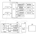
- FIG. 1 is a schematic overall configuration diagram of a urination information management system according to an embodiment of the present invention
- FIG. FIG. 2 is a schematic block diagram of a urination amount measuring device and a user terminal that constitute the urination information management system
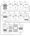
- FIG. 10 is a diagram showing an example of a display screen of a user terminal for explaining the flow of urine volume measurement processing
- FIG. 4 is an enlarged view of the operation instruction screen of FIG. 3(2);
- FIG. 1 is a diagram schematically showing a urine volume management system 1 of this embodiment.
- FIG. 2 is a schematic block diagram of the urine volume management system 1.
- This urine volume management system 1 includes a measuring device 100 for measuring body weight, a user terminal 200 as a subject terminal, and an administrator terminal 300 .
- a urine volume management system 1 is set in a medical institution such as a hospital, a subject's home, or the like. When the urine volume management system 1 is installed in a medical institution, a plurality of user terminals 200 can be used.
- the measurement device 100 corresponds to the urination volume meter of the present invention, and includes a flat casing 101.
- the user terminal 200 is composed of, for example, a smart phone or a tablet terminal.
- the measuring device 100 and the user terminal 200 are provided with short-range wireless communication circuits (hereinafter simply referred to as "communication circuits") 180 and 280, respectively, and are configured to be able to communicate wirelessly with each other.
- the administrator terminal 300 is, for example, a desktop, notebook, or tablet personal computer, and is connected to the user terminal 200 by short-range wireless communication. Note that the administrator terminal 300 and the user terminal 200 may be connected via a local network in the facility where the urine output management system 1 is installed, or via the Internet.
- the measurement apparatus 100 includes a CPU 170, a communication circuit 180, a power supply control circuit 160, an LED control circuit 165, an A/D conversion circuit 130, a USB/serial conversion circuit 145, a memory (ROM (Read Only Memory) and RAM (Random Access Memory)) 171, power supply battery 140, LED 175, and load cell 110 are mounted.
- the A/D conversion circuit 130 and the load cell 110 correspond to the weight measurement section, and the CPU 170 corresponds to the second control section.
- the load cell 110 is a type of weight sensor in which strain caused by the weight of a patient or the like sitting on the housing 101 appears as a change in resistance value.
- the load cell 110 outputs a change in resistance value as a voltage signal or a current signal.
- a signal output from the load cell 110 is converted into a digital value by the A/D conversion circuit 130 and then input to the CPU 170 .
- the USB/serial conversion circuit 145 converts various signals input/output from the USB port 173 into serial data and inputs the serial data to the CPU 170 .
- the ROM stores a program in which the processing procedure of the CPU 170 is described, and the CPU 170 functions as a control section by deploying the program in the RAM or the like and executing it. Various tables (maps) used for various calculations are also stored in the ROM.
- the CPU 170 executes various processes in the measuring device 100 according to these programs and tables. Various types of processing are not limited to those performed by software, and processing can also be performed by dedicated hardware (electronic circuits).
- the power supply control circuit 160 controls charging and discharging of the built-in power supply battery 140 and monitors the remaining amount.
- the power supply control circuit 160 converts the fluctuating voltage of the battery 140 into a required constant voltage, and supplies the constant voltage to the CPU 170, the memory 171, the load cell 110, the A/D conversion circuit 130, the communication circuit 180, and the like.
- Battery 140 is configured to be rechargeable via USB port 173 .
- the power switch 176 is a switch for turning the measuring device 100 ON/OFF. Even if the measuring device 100 is turned on by the power switch 176, in principle it is in a sleep state when not weighing in order to achieve low power consumption.
- the communication circuit 180 and some functions of the CPU 170 that controls the communication circuit 180 are activated with low power.
- the communication circuit 180 is activated periodically, and the CPU 170 is fully activated when communication is established with any of the user terminals 200 .
- the communication circuit 180 for example, it is preferable to use one that complies with the low power standard called Bluetooth (registered trademark) Low Energy.
- the CPU 170 externally displays the operating state of the measuring device 100 by means of the LED 175, which is an indicator of RGB.
- the CPU 170 changes from the low-power startup state to the state capable of high-function computation, and causes the power supply control circuit 160 to energize other units such as the load cell 110. During weight measurement, the CPU 170 starts the signal calculation of the load cell 110, so power consumption increases.
- the CPU 170 has high processing power capable of performing high-speed calculations up to floating point numbers in order to realize weight measurement. Therefore, power consumption is large if the load cell 110 and the subsequent processing circuit are kept in a standby state all the time in order to detect the load. Therefore, in the urine volume management system 1 of the present embodiment, in the sleep state, the low power consumption communication circuit 180 and the CPU 170 for controlling it are periodically turned on and off. Then, after the CPU 170 of the measuring device 100 receives the wireless communication request from the user terminal 200, the entire device including the load cell 110 is activated.
- the power consumption of the measuring device 100 in the sleep state can be limited to the power consumption of the communication circuit 180 and the CPU 170 in the low power state.
- the weight is measured twice before and after urination each time the patient urinates, so the power consumption of the measuring device 100 is significantly lower than when the weight is measured once a day, for example. increase to
- the power consumption in the sleep state is reduced in the measuring device 100 of the present embodiment, the life of the battery 40 can be dramatically extended.
- the user terminal 200 is configured by, for example, a smart phone or a tablet terminal, and configured separately from the measuring device 100 .
- the user terminal 200 includes a CPU 270, a memory 271, an input operation unit 274 consisting of a touch panel or buttons for accepting input operations, a display unit 210 for displaying a screen, a voice instruction unit 276, and a short-range wireless communication circuit 280.
- the CPU 270 functions as a first control section and an arithmetic device of the present invention.
- a plurality of user terminals 200 (for example, 1 to N; N is a natural number) may be provided. If there are multiple terminals, identification information for identifying each terminal from other terminals is stored in advance in the memory 271 .
- a control program (system software) is stored in the memory 271, and the CPU 270 functions as a control unit of the user terminal 200 by executing this program.
- the memory 271 stores application software dedicated to the urination amount management system 1. Only when the CPU 270 executes this software and transmits a wireless communication request, and the measurement device 100 receives the request, Communication is performed between the measuring device 100 and the user terminal 200 . In other words, the measuring device 100 does not react even if a wireless communication request is transmitted from a general smart phone or tablet terminal. With such a configuration, the personal information of the user who owns the user terminal 200, which is transmitted and received between the measuring device 100 and the user terminal 200, is prevented from being leaked to a third party.
- FIG. 3 is an example of a screen displayed on the display section of the user terminal 200 when the urine volume measurement process is being executed.
- the measurement device 100 is powered on by the power switch 176 when the urination amount measurement process is executed.
- the CPU 170 activates the communication circuit 180 and determines whether or not communication is established. Then, when it is determined that communication is not established, the CPU 170 enters a sleep state for a certain period of time. After a certain period of time has elapsed, CPU 170 activates communication circuit 180 again and determines whether or not communication is established.
- the measurement device 100 in the sleep state periodically repeats the process of activating the communication circuit 180 and determining whether or not communication is established.
- an initial screen for weight measurement before urination is displayed on the screen of the display unit 210 ((1) in FIG. 3).
- This initial screen displays the name and identification number of the user (subject) who owns the user terminal 200, as well as a graphical user interface (GUI) for confirming the intention to start the urination volume measurement process.
- GUI graphical user interface
- Interface button 211 is displayed. This GUI button 211 consists of a rectangular frame and the characters "start" displayed therein.
- the CPU 270 When the CPU 270 detects that the user has touched the GUI button 211, the CPU 270 activates the communication circuit 280 to transmit a wireless communication request, and determines whether or not communication with the measuring device 100 is established. . Communication is not established when the measuring device 100 is not nearby or when the main power of the measuring device 100 is turned off. When a preset timeout period in which communication is not established elapses, the CPU 270 turns off the user terminal 200 .
- the CPU 270 transmits a command C1 to the measuring device 100.
- the CPU 170 of the measuring device 100 that has received the command “C1” returns the command A1 to the user terminal 200 .
- the CPU 170 of the user terminal 200 displays a screen (operation instruction screen) for instructing the user to perform the next operation on the display unit 210 ((2) in FIG. 3).
- a command transmitted from the measuring device 100 to the user terminal 200 is given a symbol consisting of a combination of "A” and a number
- a command transmitted from the user terminal 200 to the measuring device 100 is Both are distinguished by a symbol consisting of a combination of "C” and a number.
- a command A transmitted from the measuring device 100 to the user terminal 200 corresponds to a trigger signal.
- FIG. 4 is an enlarged view of the operation instruction screen of FIG. 3(2).
- This action instruction screen includes a text message 221 (“Please step on the measuring device”) instructing the user to step on the housing 101 of the measuring device 100 in order to measure the weight, and An image 222 representing the state of trying to climb on is displayed.
- the action instruction screen also displays a bar (progress bar) 223 representing the progress of the urine volume measurement process and supplementary explanation 224 regarding the state of the measuring device 100 .
- the image 222 may be a still image or a moving image.
- the CPU 270 causes the voice instruction unit 276 to output a voice message ("Please get on the measuring device") instructing an operation.
- the user can see the text message 221 and the image 222 displayed on the screen of the display unit 210 or listen to the voice message to determine the action to be performed next.
- both the visual information such as the text message 221 and the image 222 and the auditory information such as the voice message are used to instruct the next action to be performed.
- the system is easy to use even for people with cognitive problems.
- the content of the operation instruction is represented by the image 222, the system is easy to use even for infants and foreign patients who cannot understand the content of instructions in text or voice.
- the user can visually grasp the progress of the urination measurement process from the progress bar 223 displayed on the operation instruction screen. Further, from the supplemental explanation 224, the user can proceed with the urine volume measurement process in association with the state of the measuring device 100.
- FIG. 1 A block diagram illustrating an exemplary computing environment in accordance with the present disclosure.
- the CPU 270 transmits the command "C1" again. do. If the command “A1” is not transmitted from the measuring device 100 even after repeating the process of transmitting the command “C1” a plurality of times (for example, ten times), an error screen is displayed on the display unit 210 .
- the CPU 170 of the measuring device 100 causes circuits necessary for measurement, such as the load cell 110, to transition from the sleep state to the measurable state. After that, the CPU 170 observes the change in the resistance value of the load cell 110 for a certain period of time based on the digital value obtained from the A/D conversion circuit 130 .
- a digital value representing the change in the resistance value of the load cell 110 is input from the A/D conversion circuit 130 to the CPU 170 .
- the CPU 170 detects from the digital value that the user is on the housing 101 and transmits a command A2 to the user terminal 200 .
- CPU 270 of user terminal 200 switches the screen of display unit 210 to a screen indicating that weight measurement is in progress ((3) in FIG. 3) and outputs a voice message from voice instruction unit 276.
- a character message "Measurement is in progress, please do not move on the measuring device” is displayed as a text message for explaining precautions during measurement, and the user is standing upright on the measuring device 100.
- An image of a person is displayed, and voice instruction unit 276 outputs a voice message having the same contents as the text message.
- the CPU 170 calculates the weight measurement value of the user while averaging the digital values input from the load cell 110 . As a result, even if the user moves on the housing 101 and the change in the resistance value of the load cell 110 is not stable, the weight can be stably measured.
- the CPU 170 sends a command A3 to the user terminal 200 after completing the calculation of the weight measurement value of the user.
- the CPU 270 of the user terminal 200 switches the screen of the display unit 210 to a screen indicating that the measurement has ended ((4) in FIG. 3) and outputs a voice message from the voice instruction unit 276.
- a character message "Measurement is complete, please get off the measuring device” is displayed as a text message for explaining the operation after the measurement is completed, and an image showing a state in which a person has stepped down from the measuring device 100 is displayed. be done.
- the voice instruction unit 276 outputs a voice message having the same contents as the text message.
- the digital value input from the A/D conversion circuit 130 sharply decreases.
- the CPU 170 detects that the user got off the measuring device 100 from the change in the digital value, and transmits a command A4 to the user terminal 200.
- FIG. Further, the CPU 170 obtains the weight value of the user by subtracting the measured weight value calculated from the digital value at that time from the measured weight value when the user is on the measuring device 100 .
- the determined weight value is stored in the memory 171 as the weight value before urination.
- the CPU 270 of the user terminal 200 that has received the command A4 from the measuring device 100 transmits the command C2 to the measuring device 100.
- the CPU 170 of the measuring device 100 that has received the command C2 reads out the weight value before urination from the memory 171 and transmits it to the user terminal 200 .
- the CPU 270 of the user terminal 200 that has received the weight value before urination stores the value in the memory 271 .
- CPU 270 also switches the screen of display unit 210 to an operation instruction screen ((5) in FIG. 3) for the user to instruct the next operation to be performed, and outputs a voice message from voice instruction unit 276 .
- the user terminal 200 transmits a command C3 to the measuring device 100.
- a text message "Measure again after urinating in the toilet” and an image representing the action of urinating in the toilet and the action of getting on the measuring device 100 are displayed. Also, a voice message having the same content as the text message is output from voice instruction section 276 .
- CPU 170 of measuring device 100 Upon receiving command C3 from user terminal 200, CPU 170 of measuring device 100 transmits command A5 to user terminal 200.
- the CPU 270 of the user terminal 200 that has received the command A5 disconnects communication with the measuring device 100 and puts the user terminal 200 into a sleep state.
- the CPU 270 causes the screen of the display unit 210 to display an initial screen for weight measurement after urination ((6) in FIG. 3).
- This initial screen displays a GUI button 212 for confirming the user's intention to start weight measurement processing after urination.
- This GUI button 211 is composed of a rectangular frame and the characters "Proceed to measurement after urination" displayed therein.
- the CPU 270 When the CPU 270 detects that the user has touched the GUI button 212 , the CPU 270 activates the communication circuit 280 to transmit a wireless communication request, and determines whether or not communication with the measuring device 100 is established. . Communication is not established when the measuring device 100 is not nearby or when the main power of the measuring device 100 is turned off. When the state in which communication is not established continues for a preset timeout period, the CPU 270 returns the user terminal 200 to sleep mode.
- the CPU 270 puts the user terminal 200 into the sleep state. back to When a predetermined time has elapsed after the user terminal 200 returns to the sleep state, the CPU 270 causes the screen of the display unit 210 to display the initial screen for weight measurement after urination again.
- the process of returning the user terminal 200 to the sleep state and displaying the initial screen again on the display unit 210 is repeated a plurality of times (for example, 10 times). (Snooze function). If communication is not established between the user terminal 200 and the measuring device 100 even after the above process is repeated multiple times, or if the GUI button 212 is not touch-operated, the CPU 270 stores data in the memory 271. The body weight value data is discarded, and the urination amount measurement process ends.
- the CPU 270 transmits a command C1 to the measuring device 100 .
- operations of the measuring device 100 and the user terminal 200 performed until the user's weight measurement is completed, screens displayed on the display unit 210 of the user terminal 200 ((7) to (9) in FIG. 3), And the voice message output from the voice instruction unit 276 is the same as that at the time of weight measurement before urination, so the description is omitted here.
- the CPU 170 of the measuring device 100 transmits this weight value to the user terminal 200 .
- the CPU 270 of the user terminal 200 that has received the weight value after urination reads out the weight value before urination stored in the memory 271 and calculates the amount of urination.
- the voided volume is obtained by subtracting the postvoid weight value from the prevoid weight value. If desired, weight values may be converted to volume using standard densities of urine.
- the urine volume obtained by the calculation is displayed on the screen of the display unit 210 ((10) in FIG. 3) and stored in the memory 271.
- FIG. This screen displays a GUI button 213 prompting the user to move to the next screen along with the amount of urination.
- This button 213 is composed of a rectangular frame and characters "next" displayed therein.
- the CPU 270 causes the display unit 210 to display a screen (additional information selection screen) for allowing the user to input additional information.
- a screen for selecting whether or not to urinate during sleep as additional information
- FIG. This is a screen for selecting the presence/absence of GUI buttons as selection buttons are displayed on these additional information selection screens.
- additional information in addition to the above, evaluation of the amount of urination, presence or absence of hematuria, presence or absence of pain during urination, etc. may be selected.
- the CPU 270 stores the calculated urination volume and additional information in the memory 271 together with the date and time. In addition, the CPU 270 transmits data such as urine output and additional information stored in the memory 271 to the administrator terminal 300 .
- FIG. 3(13) shows a standby screen showing that data is being transmitted from the user terminal 200 to the administrator's terminal 300, and FIG. It is an end screen showing that the amount measurement process has ended.
- the present invention is not limited to the above embodiments and can be modified as appropriate.
- an operation instruction screen is displayed on the display unit 210 of the user terminal and a voice instruction message is output from the voice instruction unit 276 at the same time. Only the message may be output from the voice instruction section 276.
- the voice message is always output from the voice instruction unit 276, but when a part of the operation instruction screen is displayed on the display unit 210 A voice message may be output from the voice instruction unit 276 at the same time.
- the urination volume management system of paragraph 1 a subject terminal having a voice instruction unit and a first control unit that controls the voice instruction unit; a urination volume meter configured to be able to wirelessly communicate with the terminal for subject, and having a weight measurement unit and a second control unit that causes the weight measurement unit to perform a weight measurement step;
- a urine volume measurement system comprising: The urination volume meter transmits a trigger signal to the first control unit of the subject terminal when each measurement step included in the two weight measurement steps is completed, When the first control section receives the trigger signal, the first control section causes the voice instruction section to output a voice instruction message instructing an operation corresponding to the trigger signal.
- the weight measurement process twice is a process in which the subject steps on the urination volume meter and measures the weight before and after urination.
- the "movement corresponding to the trigger signal" includes, for example, a movement of the subject getting on the urine volume measuring meter, a movement of getting off the urine volume measuring instrument, or going to the toilet after the first weight measurement process. Includes the act of urinating.
- the subject by listening to the voice instruction message output from the voice instruction unit of the subject terminal while the urination volume meter is performing the weight measurement process, the subject can The user can easily recognize the action to be performed next.
- the subject terminal further has a display unit,
- the first control section may display an instruction screen corresponding to the voice instruction message on the display section in conjunction with the voice instruction section.
- the instruction screen may be a character string and/or an image indicating the content of the voice instruction message.
- the subject can be instructed to perform actions by both auditory information such as a voice instruction message and visual information such as an instruction screen displayed on the display unit. can be done.
- a voice instruction message can be output from the voice instruction unit of the subject terminal.
- the first control unit receives a signal transmitted from the urine volume measuring instrument when the first weight measurement process is completed. After a predetermined time has elapsed since the first time, the voice instruction unit may output a voice instruction message prompting execution of the second weight measurement step.
- the terminal for the subject urinates. It will be in a state where it can not receive the signal from the weighing meter. Even in such a case, the urination amount management system in Section 5 outputs a voice instruction message from the voice instruction unit of the terminal for subject to instruct the subject to perform the second weight measurement (after urination). can call attention.
- the power consumption of the urination amount meter can be reduced because the weight measurement unit is in a sleep state until the weight measurement process is performed in the weight measurement unit.
- Urination amount management system 100... Measuring device 110... Load cell 130... A/D conversion circuit 140... Battery for power supply 145... USB/serial conversion circuit 160... Power supply control circuit 165... LED control circuit 170... CPU 171... Memory 173... USB port 175... LED 176...Power switch 180...Communication circuit 200...User terminal 210...Display unit 270...CPU 271...Memory 274...Input operation unit 276...Voice instruction unit 280...Near field wireless communication circuit 300...Administrator terminal
Landscapes
- Health & Medical Sciences (AREA)
- Life Sciences & Earth Sciences (AREA)
- Physics & Mathematics (AREA)
- Medical Informatics (AREA)
- Surgery (AREA)
- Biophysics (AREA)
- Pathology (AREA)
- Engineering & Computer Science (AREA)
- Biomedical Technology (AREA)
- Heart & Thoracic Surgery (AREA)
- Physiology (AREA)
- Molecular Biology (AREA)
- Urology & Nephrology (AREA)
- Animal Behavior & Ethology (AREA)
- General Health & Medical Sciences (AREA)
- Public Health (AREA)
- Veterinary Medicine (AREA)
- General Physics & Mathematics (AREA)
- Measuring And Recording Apparatus For Diagnosis (AREA)
- Measurement Of The Respiration, Hearing Ability, Form, And Blood Characteristics Of Living Organisms (AREA)
Priority Applications (1)
| Application Number | Priority Date | Filing Date | Title |
|---|---|---|---|
| JP2023531420A JP7747046B2 (ja) | 2021-06-30 | 2022-03-15 | 排尿量管理システム |
Applications Claiming Priority (2)
| Application Number | Priority Date | Filing Date | Title |
|---|---|---|---|
| JP2021-109724 | 2021-06-30 | ||
| JP2021109724 | 2021-06-30 |
Publications (1)
| Publication Number | Publication Date |
|---|---|
| WO2023276317A1 true WO2023276317A1 (ja) | 2023-01-05 |
Family
ID=84691155
Family Applications (1)
| Application Number | Title | Priority Date | Filing Date |
|---|---|---|---|
| PCT/JP2022/011651 Ceased WO2023276317A1 (ja) | 2021-06-30 | 2022-03-15 | 排尿量管理システム |
Country Status (2)
| Country | Link |
|---|---|
| JP (1) | JP7747046B2 (https=) |
| WO (1) | WO2023276317A1 (https=) |
Citations (4)
| Publication number | Priority date | Publication date | Assignee | Title |
|---|---|---|---|---|
| JP3178848U (ja) * | 2012-07-23 | 2012-10-04 | 株式会社アコーズ | 健康増進装置 |
| KR20150098709A (ko) * | 2014-02-20 | 2015-08-31 | 경운대학교 산학협력단 | 휴대기기를 이용한 작업치료 장치 및 방법 |
| CN111579040A (zh) * | 2020-06-09 | 2020-08-25 | 华中科技大学同济医学院附属协和医院 | 医疗智能马桶及其使用方法 |
| WO2021111686A1 (ja) * | 2019-12-02 | 2021-06-10 | 株式会社島津製作所 | 排尿量測定装置、排尿量管理システム、排尿量測定方法、およびプログラム |
-
2022
- 2022-03-15 JP JP2023531420A patent/JP7747046B2/ja active Active
- 2022-03-15 WO PCT/JP2022/011651 patent/WO2023276317A1/ja not_active Ceased
Patent Citations (4)
| Publication number | Priority date | Publication date | Assignee | Title |
|---|---|---|---|---|
| JP3178848U (ja) * | 2012-07-23 | 2012-10-04 | 株式会社アコーズ | 健康増進装置 |
| KR20150098709A (ko) * | 2014-02-20 | 2015-08-31 | 경운대학교 산학협력단 | 휴대기기를 이용한 작업치료 장치 및 방법 |
| WO2021111686A1 (ja) * | 2019-12-02 | 2021-06-10 | 株式会社島津製作所 | 排尿量測定装置、排尿量管理システム、排尿量測定方法、およびプログラム |
| CN111579040A (zh) * | 2020-06-09 | 2020-08-25 | 华中科技大学同济医学院附属协和医院 | 医疗智能马桶及其使用方法 |
Also Published As
| Publication number | Publication date |
|---|---|
| JPWO2023276317A1 (https=) | 2023-01-05 |
| JP7747046B2 (ja) | 2025-10-01 |
Similar Documents
| Publication | Publication Date | Title |
|---|---|---|
| EP3340882B1 (en) | Uroflowmetry systems, devices, and methods | |
| JP5997453B2 (ja) | 情報処理装置およびユーザ端末 | |
| US20090187121A1 (en) | Diary and method for medical monitoring | |
| US9126088B2 (en) | Body movement amount measuring apparatus | |
| US20130331659A1 (en) | User interface of a measurement device and system | |
| JP2008301938A (ja) | 生体電気インピーダンス測定装置、低栄養測定システム、低栄養測定方法 | |
| US20220205830A1 (en) | Secret scale and method of use thereof | |
| CN105798916A (zh) | 一种智能护理机器人控制方法及系统 | |
| JP6650534B2 (ja) | 複数の生体情報を測定する携帯用複合センサー装置および測定方法 | |
| WO2023276317A1 (ja) | 排尿量管理システム | |
| JP7484932B2 (ja) | 排尿量測定装置、排尿量管理システム、排尿量測定方法、およびプログラム | |
| WO2020054487A1 (ja) | 計測装置及び計測システム | |
| JP2000333927A (ja) | 体脂肪率計 | |
| JP7800742B2 (ja) | 排尿量計測装置 | |
| JP2005342121A (ja) | 計測報知システム、生体計測装置および携帯端末 | |
| CN104720789A (zh) | 单开关心电测量仪及测量方法 | |
| KR20160050354A (ko) | 기저귀 용변 감지 시스템 | |
| JP5465964B2 (ja) | 体重計 | |
| KR20050105783A (ko) | 휴대폰을 이용한 체지방 측정장치 및 이를 이용한 체지방측정방법 | |
| JP7679880B2 (ja) | 排尿量管理方法 | |
| JP2020075153A (ja) | 睡眠状態評価装置 | |
| KR20060057287A (ko) | 다기능 변기를 이용한 건강관리 시스템 및 그 방법 | |
| EP2789295A1 (en) | Improved measurement device, system and method | |
| JP2026023264A (ja) | トイレシステム | |
| JP2011069739A (ja) | 体重計 |
Legal Events
| Date | Code | Title | Description |
|---|---|---|---|
| 121 | Ep: the epo has been informed by wipo that ep was designated in this application |
Ref document number: 22832480 Country of ref document: EP Kind code of ref document: A1 |
|
| WWE | Wipo information: entry into national phase |
Ref document number: 2023531420 Country of ref document: JP |
|
| NENP | Non-entry into the national phase |
Ref country code: DE |
|
| 122 | Ep: pct application non-entry in european phase |
Ref document number: 22832480 Country of ref document: EP Kind code of ref document: A1 |