WO2023248985A1 - 塞栓デバイス - Google Patents
塞栓デバイス Download PDFInfo
- Publication number
- WO2023248985A1 WO2023248985A1 PCT/JP2023/022629 JP2023022629W WO2023248985A1 WO 2023248985 A1 WO2023248985 A1 WO 2023248985A1 JP 2023022629 W JP2023022629 W JP 2023022629W WO 2023248985 A1 WO2023248985 A1 WO 2023248985A1
- Authority
- WO
- WIPO (PCT)
- Prior art keywords
- basket
- proximal
- distal
- binding part
- wires
- Prior art date
- Legal status (The legal status is an assumption and is not a legal conclusion. Google has not performed a legal analysis and makes no representation as to the accuracy of the status listed.)
- Ceased
Links
Images




Classifications
-
- A—HUMAN NECESSITIES
- A61—MEDICAL OR VETERINARY SCIENCE; HYGIENE
- A61B—DIAGNOSIS; SURGERY; IDENTIFICATION
- A61B90/00—Instruments, implements or accessories specially adapted for surgery or diagnosis and not covered by any of the groups A61B1/00 - A61B50/00, e.g. for luxation treatment or for protecting wound edges
- A61B90/39—Markers, e.g. radio-opaque or breast lesions markers
-
- A—HUMAN NECESSITIES
- A61—MEDICAL OR VETERINARY SCIENCE; HYGIENE
- A61B—DIAGNOSIS; SURGERY; IDENTIFICATION
- A61B17/00—Surgical instruments, devices or methods
- A61B17/12—Surgical instruments, devices or methods for ligaturing or otherwise compressing tubular parts of the body, e.g. blood vessels or umbilical cord
- A61B17/12022—Occluding by internal devices, e.g. balloons or releasable wires
- A61B17/12099—Occluding by internal devices, e.g. balloons or releasable wires characterised by the location of the occluder
- A61B17/12109—Occluding by internal devices, e.g. balloons or releasable wires characterised by the location of the occluder in a blood vessel
- A61B17/12113—Occluding by internal devices, e.g. balloons or releasable wires characterised by the location of the occluder in a blood vessel within an aneurysm
-
- A—HUMAN NECESSITIES
- A61—MEDICAL OR VETERINARY SCIENCE; HYGIENE
- A61B—DIAGNOSIS; SURGERY; IDENTIFICATION
- A61B17/00—Surgical instruments, devices or methods
- A61B17/12—Surgical instruments, devices or methods for ligaturing or otherwise compressing tubular parts of the body, e.g. blood vessels or umbilical cord
- A61B17/12022—Occluding by internal devices, e.g. balloons or releasable wires
- A61B17/12131—Occluding by internal devices, e.g. balloons or releasable wires characterised by the type of occluding device
- A61B17/1214—Coils or wires
- A61B17/12145—Coils or wires having a pre-set deployed three-dimensional shape
-
- A—HUMAN NECESSITIES
- A61—MEDICAL OR VETERINARY SCIENCE; HYGIENE
- A61B—DIAGNOSIS; SURGERY; IDENTIFICATION
- A61B17/00—Surgical instruments, devices or methods
- A61B17/12—Surgical instruments, devices or methods for ligaturing or otherwise compressing tubular parts of the body, e.g. blood vessels or umbilical cord
- A61B17/12022—Occluding by internal devices, e.g. balloons or releasable wires
- A61B17/12131—Occluding by internal devices, e.g. balloons or releasable wires characterised by the type of occluding device
- A61B17/12168—Occluding by internal devices, e.g. balloons or releasable wires characterised by the type of occluding device having a mesh structure
- A61B17/12172—Occluding by internal devices, e.g. balloons or releasable wires characterised by the type of occluding device having a mesh structure having a pre-set deployed three-dimensional shape
-
- A—HUMAN NECESSITIES
- A61—MEDICAL OR VETERINARY SCIENCE; HYGIENE
- A61B—DIAGNOSIS; SURGERY; IDENTIFICATION
- A61B17/00—Surgical instruments, devices or methods
- A61B2017/00831—Material properties
- A61B2017/00862—Material properties elastic or resilient
-
- A—HUMAN NECESSITIES
- A61—MEDICAL OR VETERINARY SCIENCE; HYGIENE
- A61B—DIAGNOSIS; SURGERY; IDENTIFICATION
- A61B17/00—Surgical instruments, devices or methods
- A61B17/12—Surgical instruments, devices or methods for ligaturing or otherwise compressing tubular parts of the body, e.g. blood vessels or umbilical cord
- A61B17/12022—Occluding by internal devices, e.g. balloons or releasable wires
- A61B2017/1205—Introduction devices
- A61B2017/12054—Details concerning the detachment of the occluding device from the introduction device
-
- A—HUMAN NECESSITIES
- A61—MEDICAL OR VETERINARY SCIENCE; HYGIENE
- A61B—DIAGNOSIS; SURGERY; IDENTIFICATION
- A61B90/00—Instruments, implements or accessories specially adapted for surgery or diagnosis and not covered by any of the groups A61B1/00 - A61B50/00, e.g. for luxation treatment or for protecting wound edges
- A61B90/39—Markers, e.g. radio-opaque or breast lesions markers
- A61B2090/3966—Radiopaque markers visible in an X-ray image
Definitions
- the present invention relates to an embolic device for forming an embolus in a diseased part of a blood vessel.
- Endovascular treatment is one of the treatments for vascular lesions such as head and neck aneurysms, arteriovenous malformations, arteriovenous fistulas, pulmonary vascular malformations, renal vascular malformations, renal arteries, and abdominal aneurysms.
- embolization is known, in which a basket-shaped device is placed in a vascular lesion such as an aneurysm to modify blood flow and prevent the aneurysm from rupturing.
- U.S. Pat. a self-expanding type having a radially constrained elongate state and an expanded relaxed state configured to allow blood flow through the opening at a velocity below the thrombus critical velocity;
- a device with a resilient transparent shell is described.
- U.S. Pat. No. 5,002,001 discloses a filament device including a self-expanding resilient transparent shell having a proximal end, a distal end, and a longitudinal axis, the transparent shell also having at its proximal and distal ends It is described to include a plurality of elongated elastic filaments with a woven structure that is secured relative to each other.
- 5,001,000 includes a delivery catheter having a lumen extending therethrough and a left atrial appendage closure implant including a proximal collar, a distal collar, and a monolithic support frame extending between the proximal collar and the distal collar.
- the monolithic support frame has a first flexure extending from the proximal collar toward the second flexure, a first segment extending from the second flexure toward the third flexure, and a third flexure to the fourth flexure.
- a second segment extending toward the distal collar and a third segment extending from the fourth bend toward the distal collar, the monolithic support frame moves from the first restraining position to the second open position to the third semi-open position.
- US Pat. No. 5,001,202 includes an implant comprising a woven braided mesh, the implant having a proximal end with a hub, a distal end, a longitudinal axis extending from the proximal end to the distal end, a distal region and a proximal region. and a transition region located substantially perpendicular to the longitudinal axis of the implant and extending between the distal region and the proximal region, the implant having an expanded configuration when deployed, the implant having an expanded configuration.
- the implant has a region of greatest diameter extending from the proximal portion of the distal region through the transition region to the distal portion of the proximal region, the diameter of the pores in the proximal portion of the distal region describe a device in which all pores in the distal portion of the proximal region are larger.
- US Pat. No. 5,001,301 describes a device consisting of a collapsible member adapted to span the neck of an aneurysm and contact the inner wall when the device is deployed.
- U.S. Pat. No. 5,003,200 describes an apparatus having a wire, a selectively removable joint, and an expandable cage, the joint coupling the cage to the wire, and the expandable cage being configured to be configured in a collapsed configuration and expanded. It has been described that the cage can assume an expanded configuration and an expanded configuration is self-assumed by the cage when the cage is released from confinement, and that the cage expands to deploy within the body lumen. .
- embolization material such as a coil is placed inside the aneurysm to fill the aneurysm and promote thrombosis, causing the aneurysm to rupture.
- embolization technique that can prevent this from happening.
- embolization techniques in which an embolus is placed inside an aneurysm if the opening of the aneurysm or the like in the blood vessel wall is large, the embolus placed inside the aneurysm may come out from within the aneurysm.
- an indwelling device may be used that is placed within the aneurysm or in a blood vessel near the opening of the aneurysm.
- a basket-shaped device is placed in the aneurysm, and an embolus such as a coil is placed inside the device, thereby preventing the placed embolus from falling into the parent artery.
- the present invention has been made in view of the above-mentioned circumstances, and its purpose is to provide an embolic device that allows easy filling of the entire interior with an embolic material and that does not easily damage blood vessel walls and the like.
- An embolic device for an intraluminal aneurysm, the device comprising: It has a basket for storing the embolus, The basket has a plurality of wires, The basket includes a distal binding part that bundles and fixes the plurality of wires on the distal side of the basket, and a proximal side that bundles and fixes the plurality of wires on the proximal side of the basket.
- the embolic device has a binding part and an accommodating part which is a part between the distal binding part and the proximal binding part of the plurality of wires,
- the distal end of the proximal binding part is distal to the proximal end of the accommodating part.
- At least one of the wires included in the basket includes a nickel-titanium alloy, The embolic device according to any one of [1] to [6], wherein the basket is extendable in a longitudinal direction and a radial direction of the basket. [8] Any of [1] to [7], wherein at least one of the distal side binding part and the proximal side binding part is provided with an X-ray opaque part containing an X-ray opaque material. The embolic device described in .
- the embolic device has a basket pusher disposed on the proximal side of the proximal end of the proximal binding part, further comprising a connecting member that is disposed proximal to the proximal end of the proximal binding part and distal to the distal end of the basket pusher, and connects the basket and the basket pusher.
- the embolic device according to any one of [1] to [8], comprising: [10] The embolic device according to [9], wherein the connecting member is detachable.
- the basket has an outer cylinder having a distal end and a proximal end, the basket is positionable in the inner lumen of the outer cylinder;
- the distal side binding part In a state where the basket is housed in the outer cylinder, the distal side binding part has a first end that is a side far from the proximal side binding part and a first end that is close to the proximal side binding part. a second end that is a side end; In a state where the entire basket comes out of the outer cylinder and no external force is applied to the basket, the second end is located more distally than the first end [1] to [ 10].
- the distal end of the proximal binding part of the basket is distal to the proximal end of the accommodating part, so that when filling the basket with an embolic substance, The embolus sent into the interior easily comes into contact with the proximal binding part and the wire located distal to the distal end of the proximal binding part.
- the direction of movement of the embolus being fed into the basket is deflected. This makes it easier to move toward both ends of the proximal part of the basket.
- the embolic material can easily enter both ends of the proximal portion of the basket, making it easier to fill the entire interior of the basket with the embolic material.
- the embolus being fed into the basket can be The proximal binding part comes into contact with the wire located distal to the distal end of the binding part, and even if the inside of the basket is excessively filled with embolus, the proximal binding part is difficult to protrude outside the basket. Therefore, the proximal binding portion of the basket is less likely to protrude toward the parent artery, making it less likely that a thrombus will form in the parent artery and damaging other objects such as the blood vessel wall.
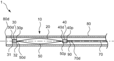
- FIG. 1 shows a cross-sectional view parallel to the longitudinal axis of an embolic device according to an embodiment of the present invention.
- FIG. 2 shows a cross-sectional view of the embolic device shown in FIG. 1 in a state where the basket is housed in the outer cylinder, parallel to the longitudinal axis direction.
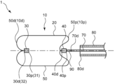
- 2 is a cross-sectional view parallel to the longitudinal axis of the embolic device shown in FIG. 1 in a state where the basket is out of the outer cylinder and no external force is applied to the basket;
- FIG. FIG. 7 is a cross-sectional view parallel to the longitudinal axis of an embolic device according to another embodiment of the present invention in a state where the basket is out of the outer cylinder and no external force is applied to the basket.
- 1 is a schematic diagram showing a state in which a conventional basket is indwelled within an aneurysm and an embolus is accommodated inside the basket.
- 1 is a schematic diagram showing a state in which a conventional basket is indwelled in an aneurysm and an embolus is excessively contained inside the basket.
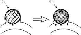
- 2 is a schematic diagram showing a state in which the embolization device shown in FIG. 1 is indwelled in an aneurysm and an embolus is housed inside a basket.
- FIG. 1 is a cross-sectional view parallel to the longitudinal axis direction of an embolic device 1 according to an embodiment of the present invention.
- some of the wires 20 of the basket 10 are shown so that the positional relationship between the distal side binding part 30, the proximal side binding part 40, and the accommodating part 50 can be easily understood. Only the wire shown in FIG. 1 is shown, and illustration of other wires is omitted.
- the proximal side refers to the user's proximal side with respect to the extending direction of the embolic device 1
- the distal side refers to the side opposite to the proximal side, that is, the side where treatment is performed with the embolic device 1 ( This refers to the lesion side).
- the direction in which the embolic device 1 extends is referred to as the longitudinal direction.
- the longitudinal axis direction can be translated as the perspective direction of the embolic device 1.
- the radial direction of the basket 10 refers to the radial direction of the basket 10
- the radially inward direction refers to the direction toward the axial center of the basket 10
- the radially outward direction refers to the direction opposite to the inward direction.
- the right side of the figure is the proximal side
- the left side of the figure is the distal side.
- the embolization device 1 of the present invention is an embolization device 1 for an intraluminal aneurysm, and includes a basket 10 for accommodating an embolus.
- the basket 10 has a distal side binding part 30 that bundles and fixes the plurality of wires 20 on the distal side of the basket 10, and a distal side binding part 30 that bundles and fixes the plurality of wires 20 on the proximal side of the basket 10.
- proximal side binding part 40 which is a part of the plurality of wires 20 between the distal side binding part 30 and the proximal side binding part 40
- housing part 50 which is a part between the distal side binding part 30 and the proximal side binding part 40 of the plural wires 20.
- the distal end 40d of the portion 40 is located on the more distal side than the proximal end 50p of the accommodating portion 50.
- the embolization device 1 is a device for embolizing an intraluminal aneurysm.
- the embolization device 1 can be used in embolization techniques, etc., in which a basket 10 for accommodating an embolus is placed in a vascular lesion such as an aneurysm to promote thrombosis and prevent the aneurysm from rupturing.
- the basket 10 is introduced into a blood vessel and placed at a target site. Specifically, the basket 10 is placed inside the aneurysm at the end of the blood vessel or the side wall, or at the distal end of the main vessel of the blood vessel, and the embolus is placed inside the basket 10 placed within the aneurysm or the distal end of the main vessel. It is placed in place to promote thrombosis of the aneurysm.
- the embolic device 1 has a basket 10. Basket 10 contains an embolus therein.
- the embolus examples include long objects such as coils, wires, and string-like objects, granular objects, and bag-like objects. Furthermore, the embolus may be solid, semi-solid, fluid, gel, liquid, or the like. Examples of the liquid embolus include a liquid that hardens, a liquid that precipitates, and the like. Among these, it is preferable that the embolus is a solid elongated object such as a coil. Since the embolic material is long, it is easy to fill the basket 10 with the embolic material, and embolization using the embolic device 1 can be performed efficiently.
- the basket 10 has a plurality of wires 20.
- the basket 10 is expandable and retractable.
- the outer shape of the basket 10 is deflated and the diameter is reduced when receiving an external force, and the outer shape is expanded and the diameter is enlarged when the basket 10 is not receiving an external force. Note that when the basket 10 is placed inside the aneurysm, the basket 10 may come into contact with the wall surface of the aneurysm, receive external force, and deform.
- the material constituting the wire 20 is preferably elastic, and includes, for example, stainless steel such as SUS304 and SUS316, platinum, nickel, cobalt, chromium, titanium, tungsten, aluminum, gold, silver, nickel-titanium alloy, Examples include a single wire, a flat wire, a double wire, a composite material wire, or a stranded metal wire made of a cobalt chromium alloy or the like. Among these, it is more preferable that the material constituting the wire 20 is a superelastic metal wire such as a nickel titanium alloy.
- the material constituting the wire 20 is a metal wire, the elasticity of the wire 20 is increased, and even if the amount of deformation of the basket 10 is large, the amount of return to the original shape becomes large. As a result, the shape of the basket 10 can be made less likely to collapse.
- the number of wires 20 that the basket 10 has may be plural, and the number of wires 20 can be selected depending on the inner diameter of the in-vivo lumen such as an aneurysm. Note that in the drawings, the number of wires 20 in the basket 10 is limited. However, in an embodiment of the present invention, the basket 10 may be made up of, for example, 8 to 64 wires 20.
- the wire diameter of the wire 20 can be set depending on the size of the basket 10, the number of wires 20, the material, etc.
- the number of wires 20 that the basket 10 has is preferably 16 or more and 32 or less.
- the basket 10 includes a distal side binding part 30 that bundles and fixes the plurality of wires 20 on the distal side of the basket 10, and a distal side binding part 30 that bundles and fixes the plurality of wires 20 on the proximal side of the basket 10. It has a proximal side binding part 40 which is fixedly fixed, and a housing part 50 which is a part between the distal side binding part 30 and the proximal side binding part 40 of the plurality of wires 20.
- a distal side of basket 10 refers to a distal portion of basket 10 and a proximal side of basket 10 refers to a proximal portion of basket 10.
- the basket 10 includes a distal side binding part 30 that bundles and fixes a plurality of wires 20, and a proximal side binding part 30 that bundles and fixes a plurality of wires 20 on the proximal side of the distal side binding part 30. It has a side binding part 40 and a housing part 50 which is a part between the distal binding part 30 and the proximal binding part 40 in the part where the wire 20 extends.
- the plurality of wires 20 can be welded, caulked together with a separate member, or bonded using an adhesive.
- Methods include fixing with brazing material, etc.
- the separate members for bundling and fixing the plurality of wires 20 include, for example, a ring-shaped member, a member having a C-shaped cross section with a cut in the ring, a wire rod. Examples include a coil-shaped member wound with a material, a member tied and fixed with a string-like material, and the like.
- the separate member for bundling and fixing the plurality of wires 20 is preferably a ring-shaped member, and more preferably the ring-shaped member is swaged.
- the separate member for bundling and fixing the plurality of wires 20 is a ring-shaped member, and by swaging, the plurality of wires 20 can be firmly fixed, and the plurality of wires 20 can be bundled. It becomes difficult to cancel.
- the material constituting the separate member for bundling and fixing the plurality of wires 20 for example, a material having less elasticity than the material constituting the wires 20 of the basket 10 can be used.
- the material constituting the separate member for bundling and fixing the plurality of wires 20 is preferably a platinum alloy such as Pt-W, Pt-Ir, or Pt-Pd. Since the material constituting the separate member for bundling and fixing the plurality of wires 20 is a platinum alloy, the fixing strength of the plurality of wires 20 can be increased. Durability can be improved.
- the basket 10 is formed into a basket shape by braiding a plurality of bent wires 20 or right-handed and left-handed helical wires 20 in the housing portion 50.
- the accommodating portion 50 of the basket 10 is constructed by braiding a right-handed helical wire 20 and a left-handed helical wire 20. Since the accommodating portion 50 of the basket 10 is constructed by braiding the right-handed helical wire 20 and the left-handed helical wire 20, a mesh-like shape formed by crossing a plurality of wires 20 is formed.
- the basket-like basket 10 can have a wall surface of .
- the distal end 40d of the proximal binding part 40 is located further distal than the proximal end 50p of the accommodating part 50. Since the distal end 40d of the proximal binding part 40 is distal to the proximal end 50p of the accommodating part 50, the proximal binding part 40 protrudes toward the distal side, and the proximal binding part 40 protrudes toward the distal side.
- a section 40 is located inside the basket 10.
- FIG. 5 is a schematic diagram showing a state in which a conventional basket 10 is placed in a aneurysm and an embolus is accommodated inside the basket 10.
- FIG. 7 is a schematic diagram of a state in which an embolic material is excessively accommodated
- FIG. 7 is a schematic diagram of a state in which the embolic device 1 of the present invention is indwelled in an aneurysm and an embolic material is accommodated inside the basket 10.
- the figure to the left of the white arrow shows the basket 10 placed within the aneurysm
- the figure to the right of the white arrow shows the state in which the embolus is accommodated inside the basket 10 placed within the aneurysm. Indicates the condition.
- the lower side of the figure is the proximal side
- the upper side of the figure is the distal side.
- the binding part that bundles and fixes the plurality of wires 20 constituting the basket 10 is located at the center of the proximal part of the basket 10, as shown in FIG.
- the binding part is pushed out from the inside of the basket 10 to the side of the parent artery.
- the proximal binding portion of the basket 10 protrudes toward the distal side, so that the embolic device 1 can be fed into the basket 10.
- the embolus is likely to come into contact with the proximal binding part and the wire 20 located distal to the distal end of the proximal binding part.
- the direction of movement of the embolus is changed. It tends to deviate and head toward both ends of the proximal portion of the basket 10.
- the embolic material easily enters both ends of the proximal portion of the basket 10, and the entire interior of the basket 10 is filled with the embolic material, making it easier to embolize the aneurysm.
- the proximal binding part 40 of the basket 10 is less likely to protrude toward the parent artery, making it difficult for thrombus to form in the parent artery, and preventing the proximal binding part 40 from coming into contact with other objects such as the blood vessel wall. It can be used to prevent damage to other objects.
- the embolic device 1 of the present invention has a case where the basket 10
- the distal end 40d of the proximal binding part 40 is distal to the proximal end 50p of the accommodating part 50 in a state where the proximal binding part 40 is outside and is not receiving any external force other than gravity.
- the outer cylinder 80 will be described later.
- the wire 20 may be present on the distal side, and the proximal portion of the basket 10 may have a concave shape, and as shown in FIG.
- the wire 20 may be present on the proximal side, and at least a portion of the proximal binding portion 40 may be located inside the basket 10. That is, the proximal binding part 40 may be located outside the basket 10 or may be located inside the basket 10.
- the basket 10 preferably has a recess 60 in which the proximal portion of the basket 10 including the proximal binding portion 40 is recessed toward the distal side. Since the basket 10 has the recess 60, the embolus sent into the basket 10 is located further distally than the proximal binding part 40 or the distal end 40d of the proximal binding part 40. This makes it easier for the embolus to come into contact with the wire 20 , which directs the advancing direction of the embolus toward both ends of the proximal portion of the basket 10 , making it easier for the embolus to enter both ends of the proximal portion of the basket 10 .
- the proximal binding portion 40 is less likely to protrude outward from the basket 10 even if the basket 10 is filled with an excessive amount of embolus. Therefore, the proximal binding part 40 is less likely to protrude toward the parent artery, making it difficult for a blood clot to form in the parent artery, and also making it difficult for the proximal binding part 40 to come into contact with other objects and cause injury. .
- the maximum depth of the recess 60 of the basket 10 is preferably greater than the length from the distal end 40d to the proximal end 40p of the proximal binding section 40.
- the maximum depth of the recess 60 of the basket 10 refers to the maximum depth of the recess of the recess 60 in the direction from the proximal side to the distal side of the basket 10. Since the maximum depth of the recess 60 is greater than the length from the distal end 40d to the proximal end 40p of the proximal binding part 40, the proximal binding part 40 protrudes inside the basket 10.
- the embolus sent into the basket 10 is likely to come into contact with the proximal binding part 40 and the wire 20 located further distal than the distal end 40d of the proximal binding part 40. Furthermore, since the maximum depth of the recess 60 is greater than the length from the distal end 40d to the proximal end 40p of the proximal binding part 40, when the inside of the basket 10 is filled with an embolic substance excessively, Also, the proximal side binding part 40 becomes difficult to protrude outward from the basket 10.
- the proximal binding part 40 of the basket 10 is less likely to protrude toward the parent artery, making it difficult for thrombus formation to occur in the parent artery, and making it difficult for the proximal binding part 40 to come into contact with other objects.
- the maximum depth of the recess 60 of the basket 10 is preferably 1.1 times or more the length from the distal end 40d to the proximal end 40p of the proximal binding part 40, and is 1.2 It is more preferably 1.3 times or more, and even more preferably 1.3 times or more.
- the proximal side binding part 40 can be It is possible to make it easier to protrude from the proximal side to the distal side of the basket 10 inside the basket 10, and to make it difficult to protrude from the distal side to the proximal side of the basket 10 outside the basket 10.
- the maximum depth of the recess 60 of the basket 10 is preferably 10 times or less, and 5 times or less, the length from the distal end 40d to the proximal end 40p of the proximal binding part 40. More preferably, it is 3 times or less.
- the length from the distal end 10d of the basket 10 to the proximal end 40p is unlikely to become too long than necessary, making it possible to make the embolization device 1 less invasive.
- the embolic device 1 preferably includes a basket pusher 70 disposed closer to the proximal end 40p of the proximal binding section 40.
- the basket pusher 70 is directly or indirectly connected to the basket 10, and the basket 10 can be moved by pushing or pulling the basket pusher 70 from the hand side.
- the material constituting the basket pusher 70 is preferably metal, and examples thereof include metals such as stainless steel, carbon steel, and nickel-titanium alloy. Among these, it is preferable that the material forming the basket pusher 70 is stainless steel. By making the material of the basket pusher 70 stainless steel, the rigidity of the basket pusher 70 can be increased. As a result, the force applied to the basket pusher 70 can be efficiently transmitted to the basket 10, making it easier to move the basket 10 in the longitudinal direction.
- the basket pusher 70 may include a handle at its proximal end to control its position and rotation in the longitudinal direction. Since the basket pusher 70 has a handle, it becomes easier to push and pull the basket pusher 70.
- the distance D1 between the straight line L1 passing through the proximal end 50p of the accommodating part 50 and perpendicular to the extending direction of the basket pusher 70 and the distal end 40d of the proximal binding part 40 is the distance D1 of the basket 10. It is preferable that the diameter is 1/10 or more of the maximum outer diameter d1. Since the distance D1 between the straight line L1 and the distal end 40d of the proximal binding part 40 is 1/10 or more of the maximum outer diameter d1 of the basket 10, the proximal binding part 40 can be held inside the basket 10. The length protruding from the proximal side to the distal side can be increased.
- the embolus sent into the inside of the basket 10 is located on the wire 20 distal side of the proximal side binding part 40 and the distal end 40d of the proximal side binding part 40. This makes it easier for the embolus to come into contact with the embolus, and the advancing direction of the embolus to move toward both ends of the proximal portion of the basket 10, making it easier to fill the entire interior of the basket 10 with the embolus.
- the distance D1 between the straight line L1 passing through the proximal end 50p of the accommodating part 50 and perpendicular to the extending direction of the basket pusher 70 and the distal end 40d of the proximal binding part 40 is 1/ of the maximum outer diameter d1 of the basket 10. It is preferably 10 or more, more preferably 1/8 or more, and even more preferably 1/5 or more.
- the distance D1 between the straight line L1 passing through the proximal end 50p of the accommodating part 50 and perpendicular to the extending direction of the basket pusher 70 and the distal end 40d of the proximal binding part 40 is equal to the maximum outer diameter d1 of the basket 10. It is preferably 1/2 or less, more preferably 1/3 or less.
- the inside of the basket 10 can be This prevents the length of the proximal side binding part 40 protruding from the proximal side to the distal side from becoming too long, making it easier for the embolus to spread throughout the basket 10. It can be filled easily.
- a straight line L1 passing through the proximal end 50p of the accommodating part 50 and perpendicular to the extending direction of the basket pusher 70, the proximal end 50p of the accommodating part 50, and the distal end of the proximal binding part 40 is 5 degrees or more and 60 degrees or less. Since the angle ⁇ 1 between the straight line L1 and the straight line L2 is 5 degrees or more and 60 degrees or less, a chevron-shaped protrusion is formed in the proximal part of the basket 10 including the proximal binding part 40 inside the basket 10. can be formed.
- the embolus being fed into the basket 10 comes into contact with the proximal binding part 40 and the wire 20 located distal to the distal end 40d of the proximal binding part 40.
- the direction of movement of the embolus tends to be directed toward both ends of the proximal portion of the basket 10, making it easier for the embolus to enter both ends of the proximal portion of the basket 10.
- a straight line L1 passing through the proximal end 50p of the accommodating part 50 and perpendicular to the extending direction of the basket pusher 70, and a straight line L2 connecting the proximal end 50p of the accommodating part 50 and the distal end 40d of the proximal binding part 40. is preferably 5 degrees or more, more preferably 15 degrees or more, even more preferably 25 degrees or more, even more preferably 30 degrees or more.
- the angle ⁇ 1 formed by L2 is preferably 60 degrees or less, more preferably 50 degrees or less, and even more preferably 40 degrees or less.
- the protrusion formed at the proximal part of the basket 10 including the proximal binding part 40 inside the basket 10 can be
- the basket 10 is less likely to become excessively large, and the internal volume of the basket 10 is less likely to decrease. As a result, it becomes possible to accommodate a large amount of embolization material inside the basket 10, and the embolization device 1 can easily fill the inside of the aneurysm.
- FIG. 2 is a sectional view parallel to the longitudinal axis direction of the embolic device 1 in a state where the basket 10 is housed in the outer tube 80.
- FIG. 4 is a cross-sectional view parallel to the longitudinal axis direction in a state in which the basket 10 has come out and no external force is applied to it
- FIG. FIG. 2 is a cross-sectional view parallel to the longitudinal axis direction in a state where no external force is applied to the basket 10. 2 to 4 as well, only some of the wires 20 included in the basket 10 are illustrated, and illustration of the other wires is omitted.
- the right side of the figure is the proximal side
- the left side of the figure is the distal side.
- the basket 10 has an outer tube 80 having a distal end 80d and a proximal end, and that the basket 10 can be placed in the inner cavity of the outer tube 80. That is, it is preferable that the basket 10 is disposed in a lumen that the outer cylinder 80 has. Since the basket 10 can be placed in the inner cavity of the outer cylinder 80, the basket 10 can be transported to a target site while being housed in the inner cavity of the outer cylinder 80. Therefore, the basket 10 is less likely to get caught on other objects such as blood vessel walls, and the basket 10 can be smoothly transported to the target site.
- the basket 10 is expandable once it exits the outer tube 80. That is, it is preferable that the basket 10 is disposed in the inner cavity of the outer cylinder 80, and that the basket 10 can be expanded when released from the outer cylinder 80.
- the basket 10 is disposed in the inner cavity of the outer cylinder 80, it is preferably in contact with the inner wall of the outer cylinder 80, and receives an external force from the outer cylinder 80 so that its outer shape is deflated and its diameter is reduced. Further, once the basket 10 is released from the outer cylinder 80, it is no longer subjected to the external force, and when there is no other external force, it is preferable that the outer shape expands and the basket 10 is expanded in diameter.
- the outer diameter can be reduced when the basket 10 is placed in the inner cavity of the outer cylinder 80. As a result, it becomes easy to transport the basket 10 to the target site, and it becomes easier to perform a procedure such as embolization using the embolization device 1.
- the outer cylinder 80 is a cylindrical member extending in the longitudinal direction, and has at least one lumen extending in the longitudinal direction. Although the number of lumens that the outer cylinder 80 has may be plural, it is preferable that the number of lumens is one. Since the outer tube 80 has one lumen, the outer diameter of the outer tube 80 can be reduced, and the embolic device 1 can be made less invasive.
- the material constituting the outer cylinder 80 is preferably resin or metal.
- the resin constituting the outer cylinder 80 include polyamide resin, polyester resin, polyurethane resin, polyolefin resin, fluorine resin, vinyl chloride resin, silicone resin, and natural rubber. These may be used alone or in combination of two or more.
- the resin constituting the outer cylinder 80 is preferably at least one of a polyamide resin, a polyester resin, a polyurethane resin, a polyolefin resin, and a fluororesin.
- the material constituting the outer cylinder 80 is at least one of a polyamide resin, a polyester resin, a polyurethane resin, a polyolefin resin, and a fluorine resin
- the surface of the outer cylinder 80 has increased slipperiness, and can be used for blood vessels, etc.
- the insertion into the lumen can be improved.
- the tube made of resin that forms the outer cylinder 80 can be manufactured using a conventional method such as extrusion molding or injection molding.
- Examples of the metal constituting the outer cylinder 80 include stainless steel such as SUS304 and SUS316, platinum, nickel, cobalt, chromium, titanium, tungsten, gold, nickel-titanium alloy, cobalt-chromium alloy, or a combination thereof.
- the tube made of metal, which becomes the outer cylinder 80 may be a tube made by spirally winding a metal wire, a tube made by knitting a metal wire, or the like. Further, the outer cylinder 80 may be a tube made of a combination of metal and resin.
- the outer cylinder 80 may be a tubular member made of resin and provided with a reinforcing material such as a metal wire.
- the wire arranged in the resin tubular member may be a fibrous material such as the above-mentioned metal, polyarylate fiber, aramid fiber, ultra-high molecular weight polyethylene fiber, PBO fiber, or carbon fiber.
- the fiber material constituting the wire may be a monofilament or a multifilament.
- the outer cylinder 80 may be composed of a single layer or a plurality of layers. Moreover, in the longitudinal axis direction, a part of the outer cylinder 80 may be composed of a single layer, and other parts may be composed of a plurality of layers.
- the outer surface of the outer cylinder 80 is coated with a hydrophilic resin. That is, it is preferable that the outer cylinder 80 has a hydrophilic resin layer on the outside of the outer cylinder 80. Since the outer surface of the outer tube 80 is coated with a hydrophilic resin, the slipperiness of the outer tube 80 is increased, and the insertability within the lumen of the living body can be improved.
- the inner surface of the outer cylinder 80 is coated with a fluororesin. That is, it is preferable that the outer cylinder 80 has a fluororesin layer inside the outer cylinder 80.
- the cross-sectional shape of the outer cylinder 80 in a cross section perpendicular to the longitudinal axis direction may be circular, elliptical, polygonal, or a combination thereof. Further, the cross-sectional shape of the lumen of the outer tube 80 in a cross section perpendicular to the longitudinal axis direction may also be circular, elliptical, polygonal, or a combination thereof.
- the basket 10 is preferably deformable and capable of sliding inside a cylinder with an inner diameter of 0.021 inch (0.5334 mm) or less, and preferably can slide inside a cylinder with an inner diameter of 0.017 inch (0.4318 mm) or less. It is more preferable that it is possible.
- the outer cylinder 80 has one lumen, it is preferable that the inner diameter of the outer cylinder 80 is 0.017 inches or less, and that the basket 10 is disposed in the inner cavity of the outer cylinder 80. . Further, when the outer cylinder 80 has a plurality of lumens, it is preferable that the inner diameter of the lumen in which the basket 10 is placed is 0.017 inch or less.
- the outer diameter of the outer cylinder 80 can be reduced, providing a minimally invasive embolization device with good insertability. It can be set to 1.
- the basket 10 has a mesh-like wall surface where the plurality of wires 20 intersect. Since the basket 10 has a mesh-like wall surface formed by a plurality of wires 20 intersecting, embolization can be carried out inside the basket 10 through the mesh-like opening where the plurality of wires 20 intersect. It can make it easier to store things. Further, since the basket 10 has a mesh-like wall surface, the opening of the wall surface of the basket 10 has a mesh-like shape in which a plurality of wires 20 intersect, so that the embolus housed inside the basket 10 can be It is possible to prevent objects from coming out of the basket 10. As a result, it becomes easier to embolize the aneurysm using the embolization device 1.
- the distal end 40d of the proximal binding part 40 is located closer to the proximal side than the proximal end 50p of the accommodating part 50. It is preferable. Further, as shown in FIG. 3, when the entire basket 10 is out of the outer cylinder 80 and no external force is applied to the basket 10, the distal end 40d of the proximal binding part 40 is connected to the housing part 50. It is preferable to distal the proximal end 50p of the proximal end 50p. When the basket 10 is housed in the outer cylinder 80, the distal end 40d of the proximal binding part 40 is located closer to the proximal end 50p of the accommodating part 50.
- the wire 20 is less likely to be disposed radially outward of the proximal binding portion 40. Therefore, the outer diameter of the basket 10 disposed in the inner cavity of the outer tube 80 can be made smaller, and the outer diameter of the outer tube 80 can also be made smaller accordingly. It can be done.
- the proximal end 30p of the distal side binding part 30 be located closer to the proximal side than the distal end 50d of the accommodating part 50. Since the proximal end 30p of the distal binding portion 30 is located closer to the proximal side than the distal end 50d of the accommodating portion 50, the distal binding portion 30 is less likely to protrude at the distal end 10d of the basket 10.
- a configuration in which the proximal end 30p of the distal side binding part 30 is located more proximally than the distal end 50d of the accommodating part 50 means that the entire basket 10 is protruding from the outer cylinder 80, etc.
- the configuration is such that no external force is applied to 10.
- the distal end 30d of the distal side binding part 30 is located on the distal side of the distal end 50d of the accommodating part 50. It is preferable.
- the distal end 30d of the distal binding part 30 is distal to the distal end 50d of the accommodating part 50.
- the wire 20 is less likely to be disposed radially outward of the distal binding portion 30. Therefore, the outer diameter of the basket 10 disposed in the inner cavity of the outer cylinder 80 can be reduced, and the outer diameter of the outer cylinder 80 can also be reduced accordingly, resulting in a minimally invasive embolization device 1. be able to.
- At least one wire 20 of the basket 10 contains a nickel titanium alloy, and that the basket 10 is extensible in the longitudinal axis direction and the radial direction of the basket 10. Since at least one wire 20 included in the basket 10 contains a nickel titanium alloy, the wire 20 has high elasticity and the basket 10 can be largely deformed. Further, since the basket 10 is extendable in the longitudinal axis direction and the radial direction of the basket 10, the volume of the basket 10 can be expanded. That is, at least one wire 20 of the basket 10 contains a nickel titanium alloy, and the basket 10 is expandable in the longitudinal direction and the radial direction, so that the basket 10 can be expanded to increase the size of the aneurysm in the lumen. The basket 10 can be brought into close contact with the wall of the aneurysm. As a result, it becomes easier to embolize the aneurysm.
- At least one of the distal side binding part 30 and the proximal side binding part 40 is provided with a radiopaque part containing a radiopaque material.
- a radiopaque part containing a radiopaque material.
- Examples of the X-ray opaque material include platinum, gold, tungsten, iridium, palladium, tantalum, and alloys of combinations of at least one of these.
- the material constituting the separate member for bundling and fixing the plurality of wires 20 described above is made of a material that is X-ray opaque.
- a separate member containing a radioactive material and bundling and fixing the plurality of wires 20 may also serve as the X-ray opaque part. Since the separate member for bundling and fixing the plurality of wires 20 also serves as an X-ray opaque part, it is possible to prevent the number of members constituting the basket 10 from increasing and increase the manufacturing efficiency of the embolic device 1. becomes.
- At least one wire 20 included in the basket 10 may include a radiopaque material. Since at least one wire 20 includes a radiopaque material, it becomes possible to confirm the state of expansion of the basket 10 and the position of the basket 10 under X-ray fluoroscopy, and the procedure using the embolic device 1 It becomes easier to carry out smoothly.
- At least one wire 20 included in the basket 10 may have a core and an outer layer covering the core.
- the material forming the core portion and the material forming the outer layer can be different, and various properties can be imparted to the wire 20. It becomes possible to do so.
- the at least one wire 20 of the basket 10 has a core and an outer layer
- materials for forming the core and the outer layer include stainless steel such as SUS304 and SUS316, platinum, nickel, cobalt
- metals include chromium, titanium, tungsten, aluminum, gold, silver, lead, barium, iodine, iridium, stainless steel, titanium, nickel-titanium alloy, and cobalt-chromium alloy.
- at least one wire 20 has a core portion containing an X-ray opaque material and an outer layer portion containing a nickel titanium alloy.
- At least one wire 20 is configured to have a core including a radiopaque material and an outer layer including a nickel titanium alloy, whereby the radiopaque material of the core While increasing the visibility of the basket 10 under X-ray fluoroscopy, the nickel-titanium alloy of the outer layer increases elasticity and makes it easier to expand the basket 10.
- the embolic device 1 is disposed proximal to the proximal end 40p of the proximal binding section 40 and distal to the distal end 70d of the basket pusher 70. It is preferable to further include a connecting member 90 for connecting the basket 10 and the basket pusher 70. Since the embolic device 1 includes the connecting member 90 that connects the basket 10 and the basket pusher 70, the basket 10 and the basket pusher 70 can be easily connected.
- the connecting member 90 is separable. That is, it is preferable that the basket 10 can be detached from the basket pusher 70 by disconnecting the connecting member 90. Since the connecting member 90 is detachable, the basket 10 can be separated from the basket pusher 70 by disconnecting the connecting member 90 after transporting the basket 10 to the target site. Therefore, the basket 10 can be easily placed at the target site.
- connecting member 90 Various methods can be used to disconnect the connecting member 90, such as a mechanical disconnection mechanism, fusing, thermal, electrical, and chemical disconnection.
- the connecting member 90 include a rod-like object, a string-like object, a clip, a member that is integrated by fitting, such as unevenness.
- synthetic resin, metal, etc. can be used as the material constituting the connecting member 90.
- the connecting member 90 may be a member different from the basket 10 or the basket pusher 70, or may be a part thereof.
- the material constituting the connecting member 90 has a property of being melted by heat
- the embolic device 1 preferably has a heating mechanism that heats the connecting member 90. Since the material constituting the connecting member 90 has a property of being melted by heat and the embolic device 1 has a heating mechanism, the connecting member 90 can be melted and broken by heating the connecting member 90 with the heating mechanism. , the basket 10 can be separated from the basket pusher 70. Therefore, the basket 10 and the basket pusher 70 can be firmly connected by the connecting member 90 until the heating mechanism is activated, and once the heating mechanism is activated, the connecting member 90 can be easily separated. As a result, the basket 10 can be placed in the target site reliably and easily.
- the material constituting the connecting member 90 which has the property of melting with heat, is preferably a thermoplastic resin, and more preferably PVA (polyvinyl alcohol). Since the material constituting the connecting member 90 is PVA, the connecting member 90 can be easily separated, and the embolic device 1 can be easily handled.
- PVA polyvinyl alcohol
- the heating mechanism is preferably connected to the basket pusher 70. Since the heating mechanism is connected to the basket pusher 70, the connecting member 90 can be heated via the basket pusher 70. Therefore, there is no need to separately provide a member for transmitting the heat of the heating mechanism to the connecting member 90, and the embolization device 1 can be made smaller. Note that the heating mechanism may be directly connected to the basket pusher 70, or may be indirectly connected to the basket pusher 70 via another member.
- the distal side binding part 30 has a first end 31 which is an end on the side far from the proximal side binding part 40, As shown in FIG. In the unlatched state, the second end 32 is preferably located more distally than the first end 31. That is, the positional relationship between the first end 31 and the second end 32 of the distal side binding part 30 in the far-near direction is different from when the basket 10 is housed in the outer tube 80 and when the entire basket 10 is housed inside the outer tube 80. It is preferable that the basket 10 be replaced with the case where the basket 10 is outside the basket 10 and no external force is applied to the basket 10.
- the distal side in the far-near direction it is preferable that the positional relationship between the first end 31 and the second end 32 of the binding part 30 is reversed.
- the first end 31 is located more distally than the second end 32 , so that the wires forming the basket 10 are not disposed inside the outer cylinder 80 . 20 and the distal side binding part 30 do not overlap. Therefore, the diameter of the basket 10 is less likely to increase, the outer cylinder 80 having a smaller diameter can be used, and the embolization device 1 can be made less invasive.
- the second end 32 is located more distally than the first end 31. The wire 20 located at the distal end of the section 50 is bent. As a result, even if the distal end 10d of the basket 10 comes into contact with another object, such as a blood vessel wall, it can be prevented from damaging the other object.
- the embolus is a coil body, and the coil body has a primary shape formed by winding a wire, and a secondary shape formed by winding a coil portion of the primary shape. is a portion including the proximal end 50p of the accommodating portion 50, and has a curved portion 100 in which the outer shape of the basket 10 is curved, and the minimum radius of curvature of the curved portion 100 is the secondary of the coil body. It is preferably larger than the radius of curvature of the shape.
- the coil body can easily fit into the curved portion 100 of the basket 10. As a result, both ends of the proximal portion of the basket 10 are easily filled with the coil body.
- the embolization device of the present invention is an embolization device for an intraluminal aneurysm, and has a basket for accommodating an embolus, the basket has a plurality of wires, and the basket has a A distal binding part that bundles and fixes multiple wires on the distal side of the basket, a proximal binding part that bundles and fixes multiple wires on the proximal side of the basket, and a It has a housing part that is a part between the distal side binding part and the proximal side binding part, and the distal end of the proximal side binding part is distal to the proximal end of the housing part. It is in.
- the embolic device of the present invention has such a configuration, when the basket is filled with embolic material, the embolic material being sent into the basket is prevented from collapsing into the proximal binding part or far from the proximal binding part. It becomes easier to contact the wire located on the distal side than the proximal end.
- the embolus comes into contact with the proximal binding part or the wire located distal to the distal end of the proximal binding part, the direction in which the embolus is being fed into the basket changes to the basket. It becomes easier to move toward both ends of the proximal part.
- the embolic material easily enters both ends of the proximal portion of the basket, and the entire interior of the basket is easily filled with the embolic material.
- the distal end of the proximal binding part is distal to the proximal end of the accommodating part, when the accommodating part is excessively filled with the embolus sent into the basket, The proximal binding portion is less likely to protrude toward the parent artery, making it less likely that a blood clot will form in the parent artery, thereby making it less likely to damage other objects such as the blood vessel wall.
- Embolic device 10 Basket 10d: Distal end of basket 10p: Proximal end of basket 20: Wire 30: Distal tie 30d: Distal end of distal tie 30p: Distal tie of distal tie Proximal end 31: First end 32: Second end 40: Proximal binding part 40d: Distal end of proximal binding part 40p: Proximal end of proximal binding part 50: Accommodating part 50d: Accommodating part 50p: Proximal end of housing part 60: Recessed part 70: Basket pusher 70d: Distal end of basket pusher 80: Outer tube 80d: Distal end of outer tube 90: Connection member 100: Curved part L1: Accommodation A straight line passing through the proximal end of the storage part and perpendicular to the extending direction of the basket pusher L2: A straight line connecting the proximal end of the storage part and the distal end of the proximal binding part D1: A straight line connecting the straight line L1 and the
Landscapes
- Health & Medical Sciences (AREA)
- Surgery (AREA)
- Life Sciences & Earth Sciences (AREA)
- Heart & Thoracic Surgery (AREA)
- Molecular Biology (AREA)
- Veterinary Medicine (AREA)
- Engineering & Computer Science (AREA)
- Biomedical Technology (AREA)
- Public Health (AREA)
- Medical Informatics (AREA)
- Nuclear Medicine, Radiotherapy & Molecular Imaging (AREA)
- Animal Behavior & Ethology (AREA)
- General Health & Medical Sciences (AREA)
- Reproductive Health (AREA)
- Vascular Medicine (AREA)
- Neurosurgery (AREA)
- Oral & Maxillofacial Surgery (AREA)
- Pathology (AREA)
- Surgical Instruments (AREA)
Abstract
Description
[1]管腔内の瘤の塞栓デバイスであって、
塞栓物を収容するためのバスケットを有しており、
前記バスケットは、ワイヤーを複数有し、
前記バスケットは、前記バスケットの遠位側において複数の前記ワイヤーを束ねて固定している遠位側結束部と、前記バスケットの近位側において複数の前記ワイヤーを束ねて固定している近位側結束部と、複数の前記ワイヤーにおける前記遠位側結束部と前記近位側結束部との間の部分である収容部と、を有しており、
前記近位側結束部の遠位端は、前記収容部の近位端よりも遠位側にある塞栓デバイス。
[2]前記バスケットは、前記近位側結束部を含む前記バスケットの近位部が遠位側に向かって窪んでいる凹部を有している[1]に記載の塞栓デバイス。
[3]前記近位側結束部の近位端よりも近位側に配置されているバスケットプッシャーを有しており、
前記収容部の近位端を通り前記バスケットプッシャーの延在方向に垂直な直線と前記近位側結束部の遠位端との距離は、前記バスケットの最大直径の1/10以上である[1]または[2]に記載の塞栓デバイス。
[4]前記近位側結束部の近位端よりも近位側に配置されているバスケットプッシャーを有しており、
前記収容部の近位端を通り前記バスケットプッシャーの延在方向に垂直な直線と、前記収容部の近位端と前記近位側結束部の遠位端とを結ぶ直線と、がなす角度は、5度以上60度以下である[1]~[3]のいずれかに記載の塞栓デバイス。
[5]遠位端と近位端とを有する外筒を有しており、
前記バスケットは、前記外筒の内腔に配置可能であり、
前記バスケットが前記外筒内に収容されている状態において、前記近位側結束部の遠位端は、前記収容部の近位端よりも近位側にある[1]~[4]のいずれかに記載の塞栓デバイス。
[6]前記遠位側結束部の近位端は、前記収容部の遠位端よりも近位側にある[1]~[5]のいずれかに記載の塞栓デバイス。
[7]前記バスケットが有する少なくとも1つの前記ワイヤーは、ニッケルチタン合金を含んでおり、
前記バスケットは、前記バスケットの長手軸方向および径方向に伸長可能である[1]~[6]のいずれかに記載の塞栓デバイス。
[8]前記遠位側結束部および前記近位側結束部の少なくとも一方に、X線不透過性材料を含んでいるX線不透過部が配されている[1]~[7]のいずれかに記載の塞栓デバイス。
[9]前記近位側結束部の近位端よりも近位側に配置されているバスケットプッシャーを有しており、
前記近位側結束部の近位端よりも近位側であって前記バスケットプッシャーの遠位端よりも遠位側に配置されており、前記バスケットと前記バスケットプッシャーとを接続する接続部材をさらに有している[1]~[8]のいずれかに記載の塞栓デバイス。
[10]前記接続部材は、切り離しが可能である[9]に記載の塞栓デバイス。
[11]遠位端と近位端とを有する外筒を有しており、
前記バスケットは、前記外筒の内腔に配置可能であり、
前記バスケットが前記外筒内に収容されている状態において、前記遠位側結束部は、前記近位側結束部に遠い側の端部である第1端と、前記近位側結束部に近い側の端部である第2端と、を有し、
前記バスケットの全体が前記外筒の外に出て、前記バスケットに外力がかかっていない状態において、前記第2端は、前記第1端よりも遠位側に位置している[1]~[10]のいずれかに記載の塞栓デバイス。
10:バスケット
10d:バスケットの遠位端
10p:バスケットの近位端
20:ワイヤー
30:遠位側結束部
30d:遠位側結束部の遠位端
30p:遠位側結束部の近位端
31:第1端
32:第2端
40:近位側結束部
40d:近位側結束部の遠位端
40p:近位側結束部の近位端
50:収容部
50d:収容部の遠位端
50p:収容部の近位端
60:凹部
70:バスケットプッシャー
70d:バスケットプッシャーの遠位端
80:外筒
80d:外筒の遠位端
90:接続部材
100:湾曲部
L1:収容部の近位端を通りバスケットプッシャーの延在方向に垂直な直線
L2:収容部の近位端と近位側結束部の遠位端とを結ぶ直線
D1:直線L1と近位側結束部の遠位端との距離
d1:バスケットの最大外径
θ1:直線L1と直線L2とがなす角度
Claims (11)
- 管腔内の瘤の塞栓デバイスであって、
塞栓物を収容するためのバスケットを有しており、
前記バスケットは、ワイヤーを複数有し、
前記バスケットは、前記バスケットの遠位側において複数の前記ワイヤーを束ねて固定している遠位側結束部と、前記バスケットの近位側において複数の前記ワイヤーを束ねて固定している近位側結束部と、複数の前記ワイヤーにおける前記遠位側結束部と前記近位側結束部との間の部分である収容部と、を有しており、
前記近位側結束部の遠位端は、前記収容部の近位端よりも遠位側にある塞栓デバイス。 - 前記バスケットは、前記近位側結束部を含む前記バスケットの近位部が遠位側に向かって窪んでいる凹部を有している請求項1に記載の塞栓デバイス。
- 前記近位側結束部の近位端よりも近位側に配置されているバスケットプッシャーを有しており、
前記収容部の近位端を通り前記バスケットプッシャーの延在方向に垂直な直線と前記近位側結束部の遠位端との距離は、前記バスケットの最大直径の1/10以上である請求項1に記載の塞栓デバイス。 - 前記近位側結束部の近位端よりも近位側に配置されているバスケットプッシャーを有しており、
前記収容部の近位端を通り前記バスケットプッシャーの延在方向に垂直な直線と、前記収容部の近位端と前記近位側結束部の遠位端とを結ぶ直線と、がなす角度は、5度以上60度以下である請求項1に記載の塞栓デバイス。 - 遠位端と近位端とを有する外筒を有しており、
前記バスケットは、前記外筒の内腔に配置可能であり、
前記バスケットが前記外筒内に収容されている状態において、前記近位側結束部の遠位端は、前記収容部の近位端よりも近位側にある請求項1に記載の塞栓デバイス。 - 前記遠位側結束部の近位端は、前記収容部の遠位端よりも近位側にある請求項1に記載の塞栓デバイス。
- 前記バスケットが有する少なくとも1つの前記ワイヤーは、ニッケルチタン合金を含んでおり、
前記バスケットは、前記バスケットの長手軸方向および径方向に伸長可能である請求項1に記載の塞栓デバイス。 - 前記遠位側結束部および前記近位側結束部の少なくとも一方に、X線不透過性材料を含んでいるX線不透過部が配されている請求項1に記載の塞栓デバイス。
- 前記近位側結束部の近位端よりも近位側に配置されているバスケットプッシャーを有しており、
前記近位側結束部の近位端よりも近位側であって前記バスケットプッシャーの遠位端よりも遠位側に配置されており、前記バスケットと前記バスケットプッシャーとを接続する接続部材をさらに有している請求項1に記載の塞栓デバイス。 - 前記接続部材は、切り離しが可能である請求項9に記載の塞栓デバイス。
- 遠位端と近位端とを有する外筒を有しており、
前記バスケットは、前記外筒の内腔に配置可能であり、
前記バスケットが前記外筒内に収容されている状態において、前記遠位側結束部は、前記近位側結束部に遠い側の端部である第1端と、前記近位側結束部に近い側の端部である第2端と、を有し、
前記バスケットの全体が前記外筒の外に出て、前記バスケットに外力がかかっていない状態において、前記第2端は、前記第1端よりも遠位側に位置している請求項1に記載の塞栓デバイス。
Priority Applications (2)
| Application Number | Priority Date | Filing Date | Title |
|---|---|---|---|
| US18/876,592 US20250366858A1 (en) | 2022-06-22 | 2023-06-19 | Embolization device |
| JP2024529007A JPWO2023248985A1 (ja) | 2022-06-22 | 2023-06-19 |
Applications Claiming Priority (2)
| Application Number | Priority Date | Filing Date | Title |
|---|---|---|---|
| JP2022100662 | 2022-06-22 | ||
| JP2022-100662 | 2022-06-22 |
Publications (1)
| Publication Number | Publication Date |
|---|---|
| WO2023248985A1 true WO2023248985A1 (ja) | 2023-12-28 |
Family
ID=89379929
Family Applications (1)
| Application Number | Title | Priority Date | Filing Date |
|---|---|---|---|
| PCT/JP2023/022629 Ceased WO2023248985A1 (ja) | 2022-06-22 | 2023-06-19 | 塞栓デバイス |
Country Status (3)
| Country | Link |
|---|---|
| US (1) | US20250366858A1 (ja) |
| JP (1) | JPWO2023248985A1 (ja) |
| WO (1) | WO2023248985A1 (ja) |
Citations (3)
| Publication number | Priority date | Publication date | Assignee | Title |
|---|---|---|---|---|
| JP2011519632A (ja) * | 2008-05-02 | 2011-07-14 | シークエント メディカル, インコーポレイテッド | 血管障害の治療のためのフィラメントデバイス |
| US20210228214A1 (en) * | 2016-02-10 | 2021-07-29 | Microvention, Inc. | Devices For Vascular Occlusion |
| US20210346032A1 (en) * | 2020-03-11 | 2021-11-11 | Microvention, Inc. | Devices for treatment of vascular defects |
-
2023
- 2023-06-19 US US18/876,592 patent/US20250366858A1/en active Pending
- 2023-06-19 WO PCT/JP2023/022629 patent/WO2023248985A1/ja not_active Ceased
- 2023-06-19 JP JP2024529007A patent/JPWO2023248985A1/ja active Pending
Patent Citations (3)
| Publication number | Priority date | Publication date | Assignee | Title |
|---|---|---|---|---|
| JP2011519632A (ja) * | 2008-05-02 | 2011-07-14 | シークエント メディカル, インコーポレイテッド | 血管障害の治療のためのフィラメントデバイス |
| US20210228214A1 (en) * | 2016-02-10 | 2021-07-29 | Microvention, Inc. | Devices For Vascular Occlusion |
| US20210346032A1 (en) * | 2020-03-11 | 2021-11-11 | Microvention, Inc. | Devices for treatment of vascular defects |
Also Published As
| Publication number | Publication date |
|---|---|
| JPWO2023248985A1 (ja) | 2023-12-28 |
| US20250366858A1 (en) | 2025-12-04 |
Similar Documents
| Publication | Publication Date | Title |
|---|---|---|
| JP7438935B2 (ja) | 外科用インプラントのための包装材 | |
| CN101808690B (zh) | 具有被关节连接段分开的可重复扩展的容积段的编织阻塞装置 | |
| CN109770985B (zh) | 植入物、植入物输送系统及其医疗组件 | |
| JP4528826B2 (ja) | 動脈瘤の治療用血管閉塞デバイス | |
| JP7830554B2 (ja) | 血管閉塞デバイス | |
| KR101961530B1 (ko) | 임플란트용 삽입 및 릴리스 시스템 | |
| JPWO2017086477A1 (ja) | 生体内留置部材及び該生体内留置部材を備える生体内留置部材配置装置 | |
| JP7063903B2 (ja) | 生体内留置具、生体内留置具送達システムおよび生体内留置具の製造方法 | |
| US20240423628A1 (en) | Medical device | |
| WO2023248985A1 (ja) | 塞栓デバイス | |
| WO2023248986A1 (ja) | 塞栓デバイス | |
| JP7097365B2 (ja) | 生体内留置具および生体内留置具送達システム | |
| JP2022516573A (ja) | 閉塞および送達を改善するためのシステム、デバイス、および方法 | |
| JP7830339B2 (ja) | 生体内留置具および生体内留置具送達システム | |
| WO2023189387A1 (ja) | 医療デバイス | |
| WO2023189386A1 (ja) | 医療デバイス | |
| JP2023146388A (ja) | 医療デバイス | |
| KR20240158341A (ko) | 조기 이식물 탈거를 방지하기 위한 근위 링크 와이어 | |
| WO2023171374A1 (ja) | 医療デバイス | |
| WO2022075182A1 (ja) | 生体内留置具および生体内留置具送達システム | |
| WO2022138383A1 (ja) | 塞栓デバイス | |
| JP2024142148A (ja) | 医療デバイス | |
| JP2024142147A (ja) | 医療デバイス | |
| JP2024142149A (ja) | 医療デバイス | |
| WO2022138384A1 (ja) | 塞栓システム |
Legal Events
| Date | Code | Title | Description |
|---|---|---|---|
| 121 | Ep: the epo has been informed by wipo that ep was designated in this application |
Ref document number: 23827168 Country of ref document: EP Kind code of ref document: A1 |
|
| ENP | Entry into the national phase |
Ref document number: 2024529007 Country of ref document: JP Kind code of ref document: A |
|
| WWE | Wipo information: entry into national phase |
Ref document number: 18876592 Country of ref document: US |
|
| NENP | Non-entry into the national phase |
Ref country code: DE |
|
| 122 | Ep: pct application non-entry in european phase |
Ref document number: 23827168 Country of ref document: EP Kind code of ref document: A1 |
|
| WWP | Wipo information: published in national office |
Ref document number: 18876592 Country of ref document: US |