WO2023248705A1 - 複合装置 - Google Patents
複合装置 Download PDFInfo
- Publication number
- WO2023248705A1 WO2023248705A1 PCT/JP2023/019677 JP2023019677W WO2023248705A1 WO 2023248705 A1 WO2023248705 A1 WO 2023248705A1 JP 2023019677 W JP2023019677 W JP 2023019677W WO 2023248705 A1 WO2023248705 A1 WO 2023248705A1
- Authority
- WO
- WIPO (PCT)
- Prior art keywords
- housing
- circuit
- switching elements
- switching element
- switching
- Prior art date
- Legal status (The legal status is an assumption and is not a legal conclusion. Google has not performed a legal analysis and makes no representation as to the accuracy of the status listed.)
- Ceased
Links
Images



Classifications
-
- F—MECHANICAL ENGINEERING; LIGHTING; HEATING; WEAPONS; BLASTING
- F04—POSITIVE - DISPLACEMENT MACHINES FOR LIQUIDS; PUMPS FOR LIQUIDS OR ELASTIC FLUIDS
- F04B—POSITIVE-DISPLACEMENT MACHINES FOR LIQUIDS; PUMPS
- F04B39/00—Component parts, details, or accessories, of pumps or pumping systems specially adapted for elastic fluids, not otherwise provided for in, or of interest apart from, groups F04B25/00 - F04B37/00
-
- H—ELECTRICITY
- H02—GENERATION; CONVERSION OR DISTRIBUTION OF ELECTRIC POWER
- H02M—APPARATUS FOR CONVERSION BETWEEN AC AND AC, BETWEEN AC AND DC, OR BETWEEN DC AND DC, AND FOR USE WITH MAINS OR SIMILAR POWER SUPPLY SYSTEMS; CONVERSION OF DC OR AC INPUT POWER INTO SURGE OUTPUT POWER; CONTROL OR REGULATION THEREOF
- H02M7/00—Conversion of AC power input into DC power output; Conversion of DC power input into AC power output
- H02M7/42—Conversion of DC power input into AC power output without possibility of reversal
- H02M7/44—Conversion of DC power input into AC power output without possibility of reversal by static converters
- H02M7/48—Conversion of DC power input into AC power output without possibility of reversal by static converters using discharge tubes with control electrode or semiconductor devices with control electrode
Definitions
- the present invention relates to a composite device having a refrigerant compression function and a heat medium heating function.
- Patent Document 1 describes a vehicle air conditioner that can be applied to vehicles such as hybrid cars and electric cars.
- the vehicle air conditioner described in Patent Document 1 includes an electric compressor that compresses refrigerant, a radiator that radiates heat from the refrigerant discharged from the electric compressor to heat air supplied into the vehicle interior, and a heat radiator that heats the air supplied into the vehicle interior.
- the refrigerant circuit includes an expansion valve that expands the refrigerant under reduced pressure, and a heat exchanger that corresponds to an evaporator that exchanges heat between the refrigerant that has been expanded under reduced pressure and the outside air.
- the vehicle air conditioner described in Patent Document 1 includes a heat medium heating electric heater that heats a heat medium and a heated heat medium that is supplied into the vehicle interior in order to assist heating of the vehicle interior by a radiator. and a heat medium-air heat exchanger that heats the air.
- the vehicle air conditioner described in Patent Document 1 can compensate for the lack of heating capacity due to the radiator.
- an electric compressor, a heat medium heating electric heater, and the like are individually provided. As a result, the overall size of the device has increased, and there is room for improvement in terms of installation space and other aspects.
- the present invention provides a composite device that can contribute to miniaturization of vehicle air conditioners, etc., and also prevents damage to switching elements used for power supply in the composite device due to surge voltage while increasing switching loss.
- the purpose is to suppress
- a composite device having a refrigerant compression function and a heat medium heating function houses a compression mechanism that compresses a refrigerant and an electric motor that drives the compression mechanism, and also has a refrigerant inlet that allows the refrigerant to flow into the inside, and a refrigerant that allows the refrigerant compressed by the compression mechanism to flow out to the outside.
- a compressor housing having an outlet, an electric heater for heating a heat medium housed therein, a heat medium inlet for causing the heat medium to flow into the inside, and a heat medium for causing the heat medium heated by the electric heater to flow out to the outside.
- the present invention includes a heater housing having a medium outlet, and a circuit housing housing therein a circuit board on which an electronic circuit including a motor drive circuit that drives the electric motor and a heater control circuit that controls the electric heater is mounted.
- the compressor housing, the heater housing and the circuit housing are integrally coupled.
- the motor drive circuit and the heater control circuit each include a switching element. The switching frequency of the switching element of the heater control circuit is set lower than the switching frequency of the switching element of the motor drive circuit, and the switching speed of the switching element of the heater control circuit is set lower than the switching frequency of the switching element of the motor drive circuit.
- the switching speed is set to be lower than the switching speed
- the electronic circuit has a parasitic inductance of a wiring connected to a switching element of the motor drive circuit that is smaller than a parasitic inductance of a wiring connected to a switching element of the heater control circuit. It is formed like this.
- the present invention it is possible to provide a composite device that can contribute to downsizing of vehicle air conditioners and the like. Further, according to the present invention, it is possible to prevent damage to switching elements used for power supply, etc. in a composite device due to surge voltage, and to suppress an increase in switching loss.
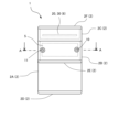
- FIG. 1 is a front view of a multifunction device according to an embodiment.
- FIG. 2 is a right side view of the multifunction device according to the embodiment.
- FIG. 1 is a top view of a multifunction device according to an embodiment.
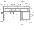
- 3 is a partial schematic sectional view of the composite device according to the embodiment, and is a view corresponding to the AA sectional view of FIG. 2.
- FIG. FIG. 2 is a diagram illustrating an example of a main part configuration of an electronic circuit including a motor drive circuit and a heater control circuit of the multifunction device according to the embodiment.
- 4 is a partial schematic sectional view of the composite device according to the embodiment, and is a view corresponding to the BB sectional view of FIG. 3.
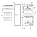
- FIG. 1 is a block diagram showing a schematic configuration of a control system of a multifunction device according to an embodiment.
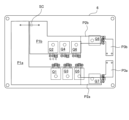
- FIG. FIG. 3 is a diagram showing an example of a wiring pattern of a circuit board on which the electronic circuit is mounted.
- FIG. 1 to 4 show a schematic configuration of a multifunction device 1 according to an embodiment of the present invention.
- FIG. 1 is a front view of the multifunction device 1 according to the embodiment
- FIG. 2 is a right side view of the multifunction device 1 according to the embodiment
- FIG. 3 is a top view of the multifunction device 1 according to the embodiment.
- 4 is a partial schematic sectional view of the composite device according to the embodiment, and is a view corresponding to the AA sectional view of FIG. 2.
- the composite device 1 has a refrigerant compression function that compresses a refrigerant, and a heat medium heating function that heats a heat medium other than the refrigerant. That is, the composite device 1 has a configuration in which a refrigerant compressor and a heat medium heating device are integrated.
- the composite device 1 can be applied to a vehicle air conditioner as described above. That is, the composite device 1 can be used by being incorporated into a refrigerant circuit in which a refrigerant circulates, and a heat medium circuit in which a heat medium is circulated by a pump section including an electric pump or the like.
- the refrigerant compression function section of the composite device 1 is incorporated in the refrigerant circuit, compresses the refrigerant that has passed through the expansion valve and the evaporator (or a heat exchanger equivalent to this), and also compresses the compressed refrigerant.
- the heat medium heating function section of the composite device 1 is incorporated in the heat medium circuit and heats the heat medium that has passed through the heat medium-air heat exchanger that heats the air supplied into the vehicle interior.
- the heating medium may be configured to supply the heating medium to the heating medium-air heat exchanger.
- the refrigerant and the heat medium may be selected arbitrarily, and for example, a gas refrigerant may be used as the refrigerant, and a liquid may be used as the heat medium.
- water including water mixed with antifreeze or the like
- the heat medium heating function may also be referred to as a water heating function (water heating device).
- the composite device 1 has a housing 2. As shown in FIG.
- the housing 2 of the composite device 1 includes a first housing 2A, a second housing 2B, a third housing 2C, a first cover 2D, a second cover 2E, and a third cover 2F, which are not shown. They are integrally connected (fastened) using fastening members such as bolts.
- the first housing 2A is formed into a substantially cylindrical shape.
- a compression mechanism 3 that compresses refrigerant and an electric motor 4 that drives the compression mechanism 3 are housed in the first housing 2A in series in the axial direction.
- the compression mechanism 3 may be a scroll compression mechanism including a fixed scroll and a movable (orbiting) scroll.
- the output shaft 4a of the electric motor 4 is connected to the compression mechanism 3 (for example, the movable (orbiting) scroll).
- first housing 2A One of the two open ends of the first housing 2A (the lower open end in FIGS. 1 and 2), that is, the open end of the first housing 2A on the compression mechanism 3 side is connected to the first cover. occluded by 2D.
- first housing 2A that houses the compression mechanism 3 that compresses refrigerant and the electric motor 4 that drives the same may also be referred to as a "compressor housing.”
- the second housing 2B is arranged on the side of the first housing 2A.
- the second housing 2B is formed into a substantially rectangular cylindrical shape.
- An electric heater 5 that heats the heat medium is housed inside the second housing 2B.
- the second housing 2B that houses the electric heater 5 that heats the heat medium may also be referred to as a "heater housing.”
- the third housing 2C is formed into a box shape with an open top surface.
- a motor drive circuit 20 that drives (controls) the electric motor 4 and a heater control circuit 30 that controls the electric heater 5 are housed inside the third housing 2C.
- a circuit board 6 on which electronic circuits including a motor drive circuit 20 and a heater control circuit 30 are mounted is housed inside the third housing 2C.
- the bottom wall 7 of the third housing 2C is connected to the other open end of the first housing 2A (the upper open end in FIGS. 1 and 2), that is, the open end of the first housing 2A on the electric motor 4 side, and the second The other open end (the upper open end in FIGS. 1 and 2) of the housing 2B is closed.
- the inside of the first housing 2A and the inside of the third housing 2C are partitioned off, and the inside of the second housing 2B and the inside of the third housing 2C are partitioned off.
- the bottom wall 7 of the third housing 2C has a first partition part 71 that partitions the inside of the first housing 2A and the inside of the third housing 2C, and a first partition part 71 that partitions the inside of the second housing 2B and the inside of the third housing 2C. It has a second partition part 72 for partitioning.
- the upper surface (opening end) of the third housing 2C is closed by the third cover 2F.
- the third housing 2C that houses the motor drive circuit 20 and the heater control circuit 30 (specifically, the circuit board 6 on which the electronic circuit including these circuits is mounted) is also referred to as a "circuit housing” or a “board housing.” can be done.
- the refrigerant compression function (electric compressor) is mainly realized by the compression mechanism 3, the electric motor 4, and the motor drive circuit 20, and the heat medium heating function is mainly realized by the electric heater 5 and the heater control circuit 30. (heat medium heating device) is realized.
- a refrigerant inlet 8 for allowing the refrigerant circulating in the refrigerant circuit to flow into the first housing 2A is formed in the first housing 2A.
- the refrigerant to be introduced is, for example, a refrigerant that has passed through an expansion valve and an evaporator (or a heat exchanger equivalent thereto), that is, a low-temperature, low-pressure refrigerant.
- the refrigerant inlet 8 is located in a portion of the first housing 2A on the third housing 2C side, that is, in the vicinity of the first partition portion 71 that partitions the inside of the first housing 2A and the inside of the third housing 2C. It is provided.
- the refrigerant inlet 8 is configured to cause the refrigerant circulating in the refrigerant circuit to flow into the first housing 2A so that at least a portion of the refrigerant flows along the first partition portion 71.
- the refrigerant sucked into the compression mechanism 3 is compressed by the compression mechanism 3, and is discharged from the compression mechanism 3 as a high-temperature, high-pressure refrigerant.
- the discharged (high temperature and high pressure) refrigerant flows out from the refrigerant outlet 9 formed in the first housing 2A, and is supplied to, for example, the above-mentioned radiator (refrigerant-air heat exchanger).
- the refrigerant outlet 9 is provided in a portion of the first housing 2A on the first cover 2D side, that is, at a position away from the refrigerant inlet 8 in the vertical direction in FIGS. 1 and 2. Therefore, in this embodiment, the refrigerant that has flowed into the first housing 2A from the refrigerant inlet 8 flows from the upper side to the lower side in FIGS. 1 and 2 within the first housing 2A.
- the first partition portion 71 may be cooled by a (low-temperature, low-pressure) refrigerant that flows into the first housing 2A through the refrigerant inlet 8.
- the electric motor 4 can be cooled by the refrigerant flowing inside the first housing 2A.
- the refrigerant inlet 8, the inside of the first housing 2A, and the refrigerant outlet 9 constitute a part of the refrigerant circuit.
- a heat medium inlet 10 is formed in the second housing 2B for allowing the heat medium circulating in the heat medium circuit to flow into the second housing 2B.
- the heat medium to be introduced is, for example, a heat medium that has passed through the above-described heat medium-air heat exchanger, that is, a low-temperature heat medium.
- the heat medium inlet 10 is located at a portion of the second housing 2B on the third housing 2C side, that is, near the second partition portion 72 that partitions the inside of the second housing 2B and the inside of the third housing 2C. and is provided on the back side in FIG. 1 (on the right side in FIG. 2).
- the heat medium inlet 10 is configured to cause the heat medium circulating in the heat medium circuit to flow into the second housing 2B so that at least a portion of the heat medium flows along the second partition portion 72. has been done.
- the heated heat medium flows out from the heat medium outlet 11 formed in the second housing 2B, and is supplied to, for example, the above-mentioned heat medium-air heat exchanger.
- the heat medium outlet 11 is located near the second partition part 72 that partitions the inside of the second housing 2B and the inside of the third housing 2C, and on the near side in FIG. 1 (left side in FIG. 2). It is set in. Therefore, in the present embodiment, the heat medium flowing into the second housing 2B from the heat medium inlet 10 flows inside the second housing 2B from the right side in FIGS. 2 and 4 along the second partition part 72. flows towards the left. That is, in the composite device 1, the flow direction of the heat medium is substantially perpendicular to the flow direction of the refrigerant.
- the second partition portion 72 may be cooled by the (low-temperature) heat medium flowing into the second housing 2B through the heat medium inlet 10. Further, the heat medium inlet 10, the inside of the second housing 2B, and the heat medium outlet 11 constitute a part of the heat medium circuit.
- the power supply line from the motor drive circuit 20 to the electric motor 4 and the power supply line from the heater control circuit 30 to the electric heater 5 are connected to the third housing in an airtight and liquidtight state, respectively. It extends through the bottom wall 7 of 2C.
- FIG. 5 is a diagram showing an example of the main part configuration of the electronic circuit including the motor drive circuit 20 and the heater control circuit 30.
- the motor drive circuit 20 drives the electric motor 4 by converting a DC voltage from a high voltage power source HV such as a high voltage battery mounted on a vehicle into a three-phase AC voltage and supplying the voltage to the electric motor 4. It is configured to drive (control). Further, the heater control circuit 30 is configured to control the temperature of the electric heater 5 by controlling the application of the high voltage power supply HV to the electric heater 5 (the energization between the high voltage power supply HV and the electric heater 5). has been done. Furthermore, in this embodiment, the electronic circuit includes a smoothing capacitor SC that smoothes the DC voltage from the high voltage power supply HV.
- the smoothing capacitor SC is connected between the power line (HV+) of the high voltage power supply HV and the ground line (HVGND). Smoothing capacitor SC smoothes the DC voltage supplied from high voltage power supply HV to motor drive circuit 20 and heater control circuit 30.
- the motor drive circuit 20 includes a first power module 21 and a first driver 22. Note that the state including the smoothing capacitor SC is sometimes referred to as the motor drive circuit 20.
- the first power module 21 includes six power switching elements (hereinafter simply referred to as "first switching elements") Q1 to Q6 and six diodes D1 to D6.
- first switching elements Q1 to Q6 may be IGBTs (insulated gate bipolar transistors).
- the first power module 21 converts the DC voltage from the high voltage power supply HV into a three-phase AC voltage and supplies it to the electric motor 4 by subjecting the first switching elements Q1 to Q6 to PWM control.
- the first power module 21 has a U-phase arm, a V-phase arm, and a W-phase arm that are provided in parallel with each other between the power line of the high-voltage power supply HV and the ground line.
- Two first switching elements Q1 and Q2 are connected in series to the U-phase arm, and diodes D1 and D2 are connected in antiparallel to each of the first switching elements Q1 and Q2, respectively.
- Two first switching elements Q3 and Q4 are connected in series to the V-phase arm, and diodes D3 and D4 are connected in antiparallel to each of the first switching elements Q3 and Q4, respectively.
- Two first switching elements Q5 and Q6 are connected in series to the W-phase arm, and diodes D5 and D6 are connected in antiparallel to each of the first switching elements Q5 and Q6, respectively.
- each of the U, V, and W phase arms are connected to the other ends of the U, V, and W phase coils of the electric motor 4, which are star-connected at one end of each. That is, the midpoint between the first switching elements Q1 and Q2 of the U-phase arm is connected to the U-phase coil, the midpoint of the first switching elements Q3 and Q4 of the V-phase arm is connected to the V-phase coil, and the W-phase A midpoint between the first switching elements Q5 and Q6 of the arm is connected to the W-phase coil.
- the first power module 21 has a ratio of the ON period of the first switching elements Q1, Q3, Q5 on the power line side of each phase arm to the ON period of the first switching elements Q2, Q4, Q6 on the ground line side. is controlled (PWM controlled), the DC voltage from the high voltage power supply HV smoothed by the smoothing capacitor SC can be converted into a three-phase AC voltage and supplied to the electric motor 4. Accordingly, the electric motor 4 and the compression mechanism 3 can be driven.
- the first driver 22 turns ON/OFF (switches) the first switching elements Q1 to Q6 (gates thereof) based on a control signal (PWM signal) from the control unit 15, which will be described later.
- the operation of the motor drive circuit 20 switching operation of the first switching elements Q1 to Q6
- the operation of the electric motor 4 and the compression mechanism 3 that is, the refrigerant compression function
- the heater control circuit 30 includes a second power module 31 and a second driver 32.
- the second power module 31 includes two switching elements (hereinafter referred to as "second switching elements") Q7 and Q8 that control the application of the high voltage power supply HV to the electric heater 5.
- the second switching elements Q7 and Q8 may be IGBTs like the first switching elements Q1 to Q6 of the motor drive circuit 20.
- one of the two second switching elements Q7 and Q8 is provided on the output side (voltage side) of the high voltage power supply HV than the electric heater 5, and the other second switching element Q7 is provided on the output side (voltage side) of the high voltage power supply HV than the electric heater 5.
- the switching element Q8 is provided closer to the ground side of the high voltage power supply HV than the electric heater 5 is.
- the second power module 31 turns ON/OFF the current between the high voltage power supply HV and the electric heater 5 by controlling the second switching elements Q7 and Q8 (PWM control). , and further the temperature of the heat medium heated by the electric heater 5.
- the second driver 32 turns ON/OFF (switching) the second switching elements Q7 and Q8 (gates thereof) based on a control signal (PWM signal) from the control unit 15. )do.
- the operation of the heater control circuit 30 (second switching elements Q7, Q8) and, by extension, the operation of the electric heater 5 (thermal medium heating function) are controlled by the control unit 15. .
- FIG. 6 is a partial schematic sectional view of the composite device 1 (corresponding to the BB sectional view in FIG. 3).
- the electronic circuit including the motor drive circuit 20 and the heater control circuit 30 (and the smoothing capacitor SC) is mounted on the circuit board 6 and housed in the third housing space S3.
- the circuit board 6 is attached to, for example, a plurality of board attachment portions 12 provided within the third housing space S3.
- each of the plurality of board attachment parts 12 is formed in the shape of a boss that protrudes upward from the bottom wall 7 of the third housing 2C (in the direction away from the first housing 2A and the second housing 2B).
- a circuit board 6 is attached to the upper surface of the board attachment part 12 with screws 13.
- the smoothing capacitor SC, the first switching elements Q1 to Q6 of the motor drive circuit 20, and the second switching elements Q7 and Q8 of the heater control circuit 30 flow into the first housing 2A from the refrigerant inlet 8. It is placed in a position where it can be cooled by a refrigerant.
- the smoothing capacitor SC, the first switching elements Q1 to Q6 of the motor drive circuit 20, and the second switching elements Q7 and Q8 of the heater control circuit 30 are connected to the bottom surface ( It is mounted on the bottom wall 7 side surface of the third housing 2C, and is arranged so as to be in thermal contact with a first partition part 71 that partitions the inside of the first housing 2A and the inside of the third housing 2C.
- "to be in thermal contact with the first partition part 71” means to be in a state where heat can be exchanged with the first partition part 71, and to be in direct contact with the first partition part 71. This includes being close enough to the first partition part 71 to allow heat exchange, and indirectly contacting the first partition part 71 via a heat exchange member having high thermal conductivity. .
- FIG. 7 is a block diagram showing a schematic configuration of the control system of the multifunction device 1 according to the embodiment.
- the control unit 15 of the composite device 1 receives an operation request (activation (including request and stop request), operation request for the heat medium heating function (including start request and stop request), etc.
- the control unit 15 also includes a first temperature detection unit 51 that detects the temperatures of the first switching elements Q1 to Q6 or their correlation values, and a second temperature detection unit 51 that detects the temperatures of the second switching elements Q7 and Q8 or their correlation values. Detection results from various detection units such as the detection unit 52 are also input.
- control unit 15 supplies the first driver 22 and/or the second driver 32 with a control signal according to the input operation request from the upper control device and/or the detection results of the various detection units, This controls the operation of the first switching elements Q1 to Q6 (that is, the operation of the motor drive circuit 20) and/or controls the second switching elements Q7 and Q8 (that is, the operation of the heater control circuit 30). It is configured as follows.
- the wiring of the electronic circuit that is, the wiring pattern on the circuit board 6 has parasitic inductance.
- the parasitic inductance of wiring tends to increase as the length of the wiring increases.
- the parasitic inductance of the wiring between the smoothing capacitor SC and each of the first switching elements Q1 to Q6 of the motor drive circuit 20 and the second switching elements Q7 and Q8 of the heater control circuit 30 is defined as L.
- di/dt is the slope of the current flowing through the switching element, and depends on the switching (turn-off) speed of the switching element.
- the switching speed of a plurality of switching elements used in the same circuit is usually limited by the parasitic inductance of the wiring related to the switching element located farthest from the smoothing capacitor (having the longest wiring length). That is, the switching speeds of the switching elements other than the switching element located farthest from the smoothing capacitor are set to be slow in the same way as for the switching element located farthest from the smoothing capacitor. Therefore, overall switching loss increases more than necessary.
- the multifunction device 1 employs the following configuration, thereby addressing the above problem.
- the drive frequency (switching frequency) of the second switching elements Q7 and Q8 of the heater control circuit 30 is lower than the drive frequency (switching frequency) of the first switching elements Q1 to Q6 of the motor drive circuit 20.
- the motor drive circuit 20 (the first switching elements Q1 to Q6) converts the DC voltage from the high voltage power supply HV into a three-phase AC voltage, and when the switching frequency of the first switching elements Q1 to Q6 becomes low, There is a possibility that distortion etc. may occur in the output waveform. If distortion or the like occurs in the output waveform, stable operation of the electric motor 4 cannot be obtained. For this reason, the switching frequency of the first switching elements Q1 to Q6 of the motor drive circuit 20 has to be increased to some extent. For example, the switching frequency of the first switching elements Q1 to Q6 needs to be on the order of kHz or higher.
- the heater control circuit 30 (second switching elements Q7, Q8) turns on/off the current between the high voltage power supply HV and the electric heater 5, the switching of the second switching elements Q7, Q8
- the frequency does not need to be that high.
- a switching frequency of the second switching elements Q7 and Q8 on the order of Hz is sufficient.
- the switching frequencies of the second switching elements Q7 and Q8 are set lower than the switching frequencies of the first switching elements Q1 to Q6.
- the switching speed of the second switching elements Q7 and Q8 of the heater control circuit 30 is slower than the switching speed of the first switching elements Q1 to Q6 of the motor drive circuit 20.
- the switching frequency of the second switching elements Q7 and Q8 of the heater control circuit 30 is the same as that of the first switching elements Q1 to Q6 of the motor drive circuit 20. It is set lower than the switching frequency. In other words, the second switching elements Q7 and Q8 have a smaller switching frequency than the first switching elements Q1 to Q6. This means that even if the switching speed of the second switching elements Q7 and Q8 is slowed down, the increase in switching loss is smaller than when the switching speed of the first switching elements Q1 to Q6 is slowed down. This means that an increase in switching loss as a whole can be suppressed.
- the switching speeds of the second switching elements Q7 and Q8 are set to be slower than the switching speeds of the first switching elements Q1 to Q6.
- the gate resistances (not shown) of the second switching elements Q7 and Q8 have a higher resistance value than the gate resistances (not shown) of the first switching elements Q1 to Q6 of the motor drive circuit 20.
- the switching speed of the second switching elements Q7 and Q8 is slower than the switching speed of the first switching elements Q1 to Q6.
- the parasitic inductance of the wiring related to the first switching elements Q1 to Q6 of the motor drive circuit 20 is smaller than the parasitic inductance of the wiring related to the second switching elements Q7 and Q8 of the heater control circuit 30. ing.
- the parasitic inductance of the wiring related to the first switching elements Q1 to Q6 of the motor drive circuit 20 is equal to the parasitic inductance of the wiring related to the second switching elements Q7 and Q8 of the heater control circuit 30. It is formed to be smaller than.
- the parasitic inductance of wiring becomes smaller as the length of the wiring becomes shorter. Therefore, in the electronic circuit of this embodiment, the smoothing capacitor SC is placed closer to the first switching elements Q1 to Q6 of the motor drive circuit 20 than the second switching elements Q7 and Q8 of the heater control circuit 30 (see FIG. 5), as a result, the length of the wiring related to the first switching elements Q1 to Q6 (specifically, the wiring between the smoothing capacitor SC and the first switching elements Q1 to Q6) is reduced to that of the second switching elements Q7, Q8. (specifically, the wiring between the smoothing capacitor SC and the second switching elements Q7 and Q8).
- the parasitic inductance of the wiring becomes smaller as the width of the wiring becomes wider (the thicker the wiring becomes). Therefore, in the electronic circuit of the present embodiment, the wiring for the first switching elements Q1 to Q6 is formed wider (thicker) than the wiring for the second switching elements Q7 and Q8. However, in this embodiment, the wiring for the second switching elements Q7 and Q8 includes a common portion with the wiring for the first switching elements Q1 to Q6. Therefore, in this embodiment, the wiring between the smoothing capacitor SC and the first switching elements Q1 to Q6 (the wiring surrounded by broken lines in FIG. 5) is the wiring between the smoothing capacitor SC and the second switching elements Q7 and Q8. Wider ( thick).
- the smoothing capacitor SC connects the second switching elements Q7 and Q8 of the heater control circuit 30. It is arranged (mounted) closer to the first switching elements Q1 to Q6 of the motor drive circuit 20 than the first switching elements Q1 to Q6 of the motor drive circuit 20. Furthermore, on the upper surface of the circuit board 6 (the surface on the third cover 2F side), the lengths of the wiring patterns P1a and P1b between the smoothing capacitor SC and the first switching elements Q1 to Q6 are the same as the lengths of the wiring patterns P1a and P1b between the smoothing capacitor SC and the second switching elements Q1 to Q6.
- the lengths are shorter than the lengths of the wiring patterns P1a+P2a and P1b+P2b between the elements Q7 and Q8.
- the wiring patterns P1a and P1b between the smoothing capacitor SC and the first switching elements Q1 to Q6 are different from other wiring patterns on the circuit board 6, for example, the first switching elements Q1 to Q6 and the second switching element Q7, It is formed wider than the second wiring patterns P2a, P2b between the electrical heaters Q8 and the third wiring patterns P3a, P3b extending from the second switching elements Q7, Q8 toward the electric heater 5.
- the composite device 1 houses therein a compression mechanism 3 that compresses refrigerant and an electric motor 4 that drives the compression mechanism 3, and has a first housing (compressor) having a refrigerant inlet 8 and a refrigerant outlet 9. a second housing (heater housing) 2B that accommodates therein an electric heater 5 that heats a heat medium and has a heat medium inlet 10 and a heat medium outlet 11; and a motor that drives the electric motor 4.
- the first housing (compressor housing) includes a third housing (circuit housing) 2C that houses therein a circuit board 6 on which an electronic circuit including a heater control circuit 30 that controls the drive circuit 20 and the electric heater 5 is mounted.
- 2A, a second housing 2B (heater housing), and a third housing (circuit housing) 2C are integrally coupled.
- Such a composite device 1 can function as a refrigerant compressor (electric compressor) that compresses a refrigerant and a heat medium heating device that heats a heat medium, and can heat the heat medium while compressing the refrigerant. Can be done. Therefore, the composite device 1 can be applied to a vehicle air conditioner as described above. By applying the composite device 1 to a vehicle air conditioner, it is possible to downsize the vehicle air conditioner compared to a conventional configuration that separately includes an electric compressor and a heat medium heating device. It is.
- a refrigerant compressor electric compressor
- the motor drive circuit 20 includes first switching elements Q1 to Q6 that convert a DC voltage into a three-phase AC voltage, and the heater control circuit 30 includes a second switching element that turns ON/OFF energization to the electric heater 5. It includes switching elements Q7 and Q8.
- the switching frequency (driving frequency) of the second switching elements Q7, Q8 is set lower than the switching frequency (driving frequency) of the first switching elements Q1 to Q6, and the switching speed of the second switching elements Q7, Q8 is
- the switching speed of the first switching elements Q1 to Q6 is set lower than the switching speed of the first switching elements Q1 to Q6, and the electronic circuit has a parasitic inductance of wiring related to the first switching elements Q1 to Q6 that is lower than a parasitic inductance of wiring related to the second switching elements Q7 and Q8. It is also designed to be smaller.
- the smoothing capacitor SC is located closer to the first switching elements Q1 to Q6 of the motor drive circuit 20 than the second switching elements Q7 and Q8 of the heater control circuit 30,
- the lengths of the wiring patterns P1a and P1b between the smoothing capacitor SC and the first switching elements Q1 to Q6 are shorter than the lengths of the wiring patterns P1a+P2a and P1b+P2b between the smoothing capacitor SC and the second switching elements Q7 and Q8. It has become.
- wiring patterns P1a and P1b between the smoothing capacitor SC and the first switching elements Q1 to Q6 include wiring patterns P2a and P2b between the first switching elements Q1 to Q6 and the second switching elements Q7 and Q8. It is formed wider than other wiring patterns on the circuit board 6.
- the first switching elements Q1 to Q6 and the second switching elements Q7 and Q8 are prevented from being damaged by surge voltage without impairing the refrigerant compression function and the heat medium heating function. It is possible to suppress an increase in switching loss due to the two switching elements Q7 and Q8. Specifically, for the first switching elements Q1 to Q6, by reducing the parasitic inductance of the wiring related to these elements, damage due to surge voltage is prevented without slowing down the switching speed (increasing switching loss). On the other hand, with respect to the second switching elements Q7 and Q8, damage due to surge voltage is prevented by reducing the switching speed, and increase in switching loss is suppressed by reducing the switching frequency.
- the refrigerant inlet 8 of the first housing (compressor housing) 2A is a first housing that partitions the inside of the first housing (compressor housing) 2A and the inside of the third housing (circuit housing) 2C.
- the smoothing capacitor SC, the first switching elements Q1 to Q6, and the second switching elements Q7 and Q8 are provided near the partition part 71, and in the third housing (circuit housing) 2C, the smoothing capacitor SC, the first switching elements Q1 to Q6, and the second switching elements Q7 and Q8 are provided in the vicinity of the first partition part 71. are placed so that they are in contact with each other.
- the smoothing capacitor SC, the first switching elements Q1 to Q6, and the second switching elements Q7, Q8 are connected to the first partition part 71 that can be cooled by the refrigerant flowing into the first housing (compressor housing). It can be effectively cooled by heat exchange. That is, high cooling performance (heat dissipation performance) for the smoothing capacitor SC, the first switching elements Q1 to Q6, and the second switching elements Q7 and Q8 is ensured, and as a result, stable operation of the composite device 1 can be realized.
- the smoothing capacitor SC, the first switching elements Q1 to Q6, and the second switching elements Q7 and Q8 are arranged so as to be in thermal contact with the first partition portion 71.
- the heat medium inlet 10 of the second housing (heater housing) 2B is a second partition part that partitions the inside of the second housing 2B (heater housing) 2B and the inside of the third housing (circuit housing) 2C. 72, and the second partition part 72 can be cooled by the heat medium flowing into the second housing 2B. Therefore, the smoothing capacitor SC, the first switching elements Q1 to Q6, and the second switching elements Q7 and Q8 may be arranged so as to be in thermal contact with the second partition part 72.
- some of the smoothing capacitor SC, the first switching elements Q1 to Q6, and the second switching elements Q7 and Q8 are arranged so as to be in thermal contact with the first partition part 71, and the rest are placed in thermal contact with the second partition part 72. may be placed so that they are in contact with each other. Even in this manner, cooling performance (heat dissipation performance) for the smoothing capacitor SC, the first switching elements Q1 to Q6, and the second switching elements Q7 and Q8 can be ensured.
- the composite device 1 is mainly applied to a vehicle air conditioner. However, it is not limited to this.
- the composite device 1 can be applied to various devices and systems that utilize an electric compressor that compresses a refrigerant and a heat medium heating device that heats a heat medium.
- SYMBOLS 1 Compound device, 2... Housing, 2A... First housing (compressor housing), 2B... Second housing (heater housing), 2C... Third housing (circuit housing), 3... Compression mechanism, 4... Electric motor, 5... Electric heater, 6... Circuit board, 8... Refrigerant inlet, 9... Refrigerant outlet, 10... Heat medium inlet, 11... Heat medium outlet, 15... Control unit, 20... Motor drive circuit, 30... Heater Control circuit, Q1 to Q6...first switching element (switching element of motor drive circuit), Q7, Q8...second switching element (switching element of heater control circuit), SC...smoothing capacitor
Landscapes
- Engineering & Computer Science (AREA)
- Mechanical Engineering (AREA)
- General Engineering & Computer Science (AREA)
- Power Engineering (AREA)
- Compressor (AREA)
- Inverter Devices (AREA)
- Air-Conditioning For Vehicles (AREA)
Abstract
Description
Claims (6)
- 冷媒圧縮機能及び熱媒体加熱機能を有する複合装置であって、
冷媒を圧縮する圧縮機構及び前記圧縮機構を駆動する電動モータを内部に収容すると共に、冷媒を内部に流入させる冷媒流入口及び前記圧縮機構で圧縮された冷媒を外部に流出させる冷媒流出口を有する圧縮機ハウジングと、
熱媒体を加熱する電気ヒータを内部に収容すると共に、熱媒体を内部に流入させる熱媒体流入口及び前記電気ヒータで加熱された熱媒体を外部に流出させる熱媒体流出口を有するヒータハウジングと、
前記電動モータを駆動するモータ駆動回路及び前記電気ヒータを制御するヒータ制御回路を含む電子回路が実装された回路基板を収容する回路ハウジングと、
を含み、
前記圧縮機ハウジング、前記ヒータハウジング及び前記回路ハウジングは、一体的に結合されており、
前記モータ駆動回路及び前記ヒータ制御回路は、それぞれスイッチング素子を含み、
前記ヒータ制御回路のスイッチング素子のスイッチング周波数は、前記モータ駆動回路のスイッチング素子のスイッチング周波数よりも低く設定され、
前記ヒータ制御回路のスイッチング素子のスイッチング速度は、前記モータ駆動回路のスイッチング素子のスイッチング速度よりも遅く設定され、
前記電子回路は、前記モータ駆動回路のスイッチング素子に関する配線の寄生インダクタンスが前記ヒータ制御回路のスイッチング素子に関する配線の寄生インダクタンスよりも小さくなるように形成されている、
複合装置。 - 前記モータ駆動回路のスイッチング素子は、電源からの直流電圧を交流電圧に変換するように構成され、
前記ヒータ制御回路のスイッチング素子は、前記電源と前記電気ヒータとの間の通電をON/OFFするように構成され、
前記電子回路は、前記電源からの直流電圧を平滑化する平滑コンデンサをさらに含み、
前記回路基板において、前記平滑コンデンサは、前記ヒータ制御回路のスイッチング素子よりも前記モータ駆動回路のスイッチング素子に近い位置に配置されている、
請求項1に記載の複合装置。 - 前記回路基板において、前記平滑コンデンサと前記モータ駆動回路のスイッチング素子との間の配線パターンの長さが前記平滑コンデンサと前記ヒータ制御回路のスイッチング素子との間の配線パターンの長さよりも短い、請求項2に記載の複合装置。
- 前記回路基板において、前記平滑コンデンサと前記モータ駆動回路のスイッチング素子との間の配線パターンが他の配線パターンよりも幅広に形成されている、請求項2に記載の複合装置。
- 前記圧縮機ハウジングの内部と前記回路ハウジングの内部とが第1仕切部で仕切られていると共に、前記圧縮機ハウジングの前記冷媒流入口が前記第1仕切部の近傍に設けられており、
前記回路ハウジング内において、前記平滑コンデンサ、前記モータ駆動回路のスイッチング素子及び前記ヒータ制御回路のスイッチング素子は、前記第1仕切部に熱的に接触するように配置されている、
請求項2~4のいずれか一つに記載の複合装置。 - 前記ヒータハウジングの内部と前記回路ハウジングの内部とが第2仕切部で仕切られていると共に、前記ヒータハウジングの前記熱媒体流入口が前記第2仕切部の近傍に設けられており、
前記回路ハウジング内において、前記平滑コンデンサ、前記モータ駆動回路のスイッチング素子及び前記ヒータ制御回路のスイッチング素子は、前記第2仕切部に熱的に接触するように配置されている、
請求項2~4のいずれか一つに記載の複合装置。
Priority Applications (1)
| Application Number | Priority Date | Filing Date | Title |
|---|---|---|---|
| CN202380046348.1A CN119301359A (zh) | 2022-06-24 | 2023-05-26 | 复合装置 |
Applications Claiming Priority (2)
| Application Number | Priority Date | Filing Date | Title |
|---|---|---|---|
| JP2022101523A JP7779809B2 (ja) | 2022-06-24 | 2022-06-24 | 複合装置 |
| JP2022-101523 | 2022-06-24 |
Publications (1)
| Publication Number | Publication Date |
|---|---|
| WO2023248705A1 true WO2023248705A1 (ja) | 2023-12-28 |
Family
ID=89379761
Family Applications (1)
| Application Number | Title | Priority Date | Filing Date |
|---|---|---|---|
| PCT/JP2023/019677 Ceased WO2023248705A1 (ja) | 2022-06-24 | 2023-05-26 | 複合装置 |
Country Status (3)
| Country | Link |
|---|---|
| JP (1) | JP7779809B2 (ja) |
| CN (1) | CN119301359A (ja) |
| WO (1) | WO2023248705A1 (ja) |
Citations (3)
| Publication number | Priority date | Publication date | Assignee | Title |
|---|---|---|---|---|
| JPH11115467A (ja) * | 1997-10-13 | 1999-04-27 | Toyota Autom Loom Works Ltd | 自動車用空調装置 |
| JP2012127328A (ja) * | 2010-12-17 | 2012-07-05 | Denso Corp | 圧縮機 |
| JP2016096680A (ja) * | 2014-11-14 | 2016-05-26 | 古河電気工業株式会社 | 電力制御装置および電力制御方法 |
Family Cites Families (2)
| Publication number | Priority date | Publication date | Assignee | Title |
|---|---|---|---|---|
| JP4988665B2 (ja) * | 2008-08-06 | 2012-08-01 | 日立オートモティブシステムズ株式会社 | 半導体装置および半導体装置を用いた電力変換装置 |
| JP6113457B2 (ja) | 2012-10-25 | 2017-04-12 | 三菱重工業株式会社 | 電動圧縮機およびこれを備えた車両用空調装置 |
-
2022
- 2022-06-24 JP JP2022101523A patent/JP7779809B2/ja active Active
-
2023
- 2023-05-26 WO PCT/JP2023/019677 patent/WO2023248705A1/ja not_active Ceased
- 2023-05-26 CN CN202380046348.1A patent/CN119301359A/zh active Pending
Patent Citations (3)
| Publication number | Priority date | Publication date | Assignee | Title |
|---|---|---|---|---|
| JPH11115467A (ja) * | 1997-10-13 | 1999-04-27 | Toyota Autom Loom Works Ltd | 自動車用空調装置 |
| JP2012127328A (ja) * | 2010-12-17 | 2012-07-05 | Denso Corp | 圧縮機 |
| JP2016096680A (ja) * | 2014-11-14 | 2016-05-26 | 古河電気工業株式会社 | 電力制御装置および電力制御方法 |
Also Published As
| Publication number | Publication date |
|---|---|
| CN119301359A (zh) | 2025-01-10 |
| JP7779809B2 (ja) | 2025-12-03 |
| JP2024002373A (ja) | 2024-01-11 |
Similar Documents
| Publication | Publication Date | Title |
|---|---|---|
| JP6203492B2 (ja) | インバータ一体型電動圧縮機 | |
| US8820105B2 (en) | Medium voltage power controller | |
| JP2001289549A (ja) | 冷蔵庫制御装置 | |
| JP2021169788A (ja) | 電動圧縮機 | |
| US8544290B2 (en) | Medium voltage variable speed drive for a chiller unit | |
| EP2191991A1 (en) | Electric compressor integrated with inverter | |
| WO2023228644A1 (ja) | 複合装置 | |
| JP7779809B2 (ja) | 複合装置 | |
| JP7783132B2 (ja) | 複合装置 | |
| JP7630014B2 (ja) | 複合装置 | |
| JP7788848B2 (ja) | 複合装置 | |
| JP2023170364A (ja) | 複合装置 | |
| JP2023158950A (ja) | 複合装置 | |
| WO2023248708A1 (ja) | 複合装置 | |
| JP7758561B2 (ja) | 複合装置 | |
| JP2024030237A (ja) | 複合装置 | |
| JP7175404B2 (ja) | 熱源側ユニット | |
| KR102754664B1 (ko) | 전동 압축기 | |
| HK1136339B (en) | Compressor power control |
Legal Events
| Date | Code | Title | Description |
|---|---|---|---|
| 121 | Ep: the epo has been informed by wipo that ep was designated in this application |
Ref document number: 23826893 Country of ref document: EP Kind code of ref document: A1 |
|
| WWE | Wipo information: entry into national phase |
Ref document number: 202380046348.1 Country of ref document: CN |
|
| WWP | Wipo information: published in national office |
Ref document number: 202380046348.1 Country of ref document: CN |
|
| NENP | Non-entry into the national phase |
Ref country code: DE |
|
| 122 | Ep: pct application non-entry in european phase |
Ref document number: 23826893 Country of ref document: EP Kind code of ref document: A1 |