WO2023248593A1 - 画像推定方法、評価値推定方法、及び画像推定装置 - Google Patents
画像推定方法、評価値推定方法、及び画像推定装置 Download PDFInfo
- Publication number
- WO2023248593A1 WO2023248593A1 PCT/JP2023/015216 JP2023015216W WO2023248593A1 WO 2023248593 A1 WO2023248593 A1 WO 2023248593A1 JP 2023015216 W JP2023015216 W JP 2023015216W WO 2023248593 A1 WO2023248593 A1 WO 2023248593A1
- Authority
- WO
- WIPO (PCT)
- Prior art keywords
- image
- learning
- estimated
- conversion
- transformed
- Prior art date
- Legal status (The legal status is an assumption and is not a legal conclusion. Google has not performed a legal analysis and makes no representation as to the accuracy of the status listed.)
- Ceased
Links
Images


Classifications
-
- G—PHYSICS
- G06—COMPUTING OR CALCULATING; COUNTING
- G06T—IMAGE DATA PROCESSING OR GENERATION, IN GENERAL
- G06T5/00—Image enhancement or restoration
- G06T5/50—Image enhancement or restoration using two or more images, e.g. averaging or subtraction
-
- G—PHYSICS
- G06—COMPUTING OR CALCULATING; COUNTING
- G06T—IMAGE DATA PROCESSING OR GENERATION, IN GENERAL
- G06T7/00—Image analysis
Definitions
- the present invention relates to an image estimation method, an evaluation value estimation method, and an image estimation device.
- the present invention claims priority to the Japanese patent application number 2022-098864 filed on June 20, 2022, and for designated countries where reference to documents is allowed, the contents described in the application are Incorporated into this application by reference.
- Patent Document 1 describes a method for automatically inspecting shape defects in welded parts using machine learning.
- image processing based on machine learning covers a wide range of areas, including semantic segmentation, recognition, image classification, image conversion, and image quality improvement.
- the learning of the estimation engine is performed using an estimated image output from the estimation engine using an image of the evaluation target for learning (learning image) as input,
- the internal parameters of the estimation engine are updated so that the difference from a high-quality image (correct image) that is a correct estimated image taught in advance is reduced.
- the learning of the estimation engine is performed using the training image as input and the estimated image output from the estimation engine, as in the case of image quality improvement.
- the internal parameters of the estimation engine are updated so that the difference from the correct evaluation value taught in advance (correct evaluation value) becomes smaller.
- the evaluation value include evaluation results such as the quality level, presence or absence of defects, and degree of abnormality of the evaluation object.
- the estimation performance of the estimation engine can be improved even with a small number of learning images.
- FIG. 1 is a schematic diagram showing an example of the entire processing sequence performed by the visual inspection system according to the present embodiment.
- the visual inspection system according to this embodiment is an example of an image estimation device, and executes an image estimation method.
- the image estimation method is a method executed by a computer, and includes a first learning image acquisition step of acquiring a plurality of learning images f of a learning object, and a conversion process to the plurality of learning images f.
- the method is characterized in that the patterns of the plurality of learning images f are made uniform with respect to the conversion items. Further, the estimation engine is characterized in that it receives an image as input and estimates an image restored image, a super-resolution image, or an enhanced image that emphasizes any one of a region of interest.
- FIG. 2 is a schematic diagram showing an example of input and output images of the visual inspection system according to the present embodiment.
- the structures and appearances of evaluation objects are diverse, and the types of defects that occur there are also diverse.
- Figures 2 (a1) to (f1) are examples of input images taken when two large and small gears are photographed as evaluation objects, and the defects, in order, are a small foreign object 200, a large foreign object 201, a chip 202, a crack 203, and a gear surface. roughness and deformation of the gear outline.
- FIGS. 2(a2) to (f2) are high-quality images corresponding to FIGS. 2(a1) to (f1), respectively, in which defects such as foreign objects 204, 205, chips 206, and cracks 207 are emphasized, and The surface texture and gear outline (edge) are clear.
- the internal learning estimation engine In the external appearance inspection system in this embodiment, the internal learning estimation engine.
- the overall processing sequence in this embodiment will be described with reference to FIG.
- the processing sequence is broadly divided into a learning phase 100 and an operation phase 101.
- the visual inspection system images the evaluation target object 102 for learning and obtains a learning image f(104) (S103). Images are obtained by capturing digital images of the surface or interior of the evaluation target using an imaging device such as a CCD (Charge Coupled Device) camera, optical microscope, charged particle microscope, ultrasonic inspection device, or X-ray inspection device. . Note that another example of "acquisition” may be to simply receive an image captured by another system and store it in the storage resource of the visual inspection system. Further, the visual inspection system may process still images taken one by one, or may perform continuous real-time processing on moving images taken continuously at 30 fps (frames per second), for example.
- CCD Charge Coupled Device
- the visual inspection system collects information on how each transformation item was transformed or what the state was before transformation for each input image h as transformation parameters 123. Save to. By performing the inverse transformation U based on the transformation parameters 123, the visual inspection system can restore information excluded by the transformation T for each image.
- Examples of conversion items for conversion T and inverse conversion U> As described above, in this embodiment, among the information included in an image, information that should be input to a machine learning estimation engine and other information are considered separately, and the latter information is excluded by transformation T. Further, among the information excluded by the transformation T, information necessary for the final output image is restored by the inverse transformation U.
- each of the transformation T and the inverse transformation U may include a plurality of transformation items.
- specific examples of the conversion items 107 and 114 will be described. Specific examples of the conversion items 107 and 114 include position, rotation, inversion, magnification, distortion, image brightness, image contrast, noise, shading, shadow, and the like.
- FIG. 3 is a diagram schematically showing an example where the conversion items are position, rotation, and magnification.
- FIGS. 3(a1) and (b1) are schematic diagrams each showing an example of two learning images f obtained by imaging an evaluation object for learning.
- the evaluation objects in these two images are two large and small gears, and the structure and size of each are similar, and the attached foreign matter is also the same, but the positional deviation on the images of the evaluation objects, There are differences in rotation and magnification.
- Rectangular dotted line frames 300 and 301 surrounding the two gears are auxiliary lines for indicating the positional shift, rotation, and difference in magnification of the evaluation object between images, and are not drawn on the actual captured image.
- the user selects the displacement, rotation, and magnification as the conversion items of the conversion T, and then the visual inspection system applies the conversion T.
- the evaluation target on the image is made uniform at the same position, in the same direction, and at the same magnification. Note that the appearance inspection system may automatically select the conversion item for conversion T.
- the evaluation target object is rotated using the reference value 108 as the angle at which the centers of the two gears are lined up side by side in the converted image f'.
- the reference value 108 for each conversion item is not limited to the illustrated example, and can be set arbitrarily.
- the reference value may be automatically calculated by the visual inspection system based on the learning image. In this case, for example, the average value or median value of the above-mentioned angles in the plurality of learning images f may be used as the reference value.
- the visual inspection system may select one of the plurality of learning images f and use the above-mentioned angle in the selected learning image f as the reference value. In this case, the states of the other learning images will be matched to the state of the selected learning image f.
- the visual inspection system may employ a reference value input by the user.
- the visual inspection system may set multiple reference values for one conversion item.
- processing such as adjusting the state of each learning image to the state closest to a plurality of reference values may be considered.
- the smaller the number of reference values the more variations in learning images will be reduced.
- FIGS. 3(a3) and (b3) are schematic diagrams showing an example of the estimated image H'.
- FIGS. 3(a4) and 3(b4) are schematic diagrams showing an example of the inversely transformed estimated image H.
- the rectangular dotted line frames 309 and 310 surrounding the two gears are the same as the corresponding dotted line frames 300 and 301 in the input image, and the information on the position, direction, and magnification that differs from image to image is restored. ing.
- magnification is used as a conversion item, even if the actual size of the evaluation object is different, it is possible to equalize the apparent size of the evaluation object on the image using transformation T. Further, although not shown, it is possible to make the appearance uniform by adopting not only rotation but also inversion of the image as a conversion item.
- FIG. 4 is a diagram schematically showing an example in which the conversion items are rotation and distortion.
- the visual inspection system performs a transformation T on the input image h (FIG. 4(a)), and creates a transformed image h' (FIG. 4(a)) in which the orientation and distortion of the evaluation target on the image are converted to reference values. b)) and input it into the estimation engine.
- the estimation engine estimates an estimated image H' (FIG. 4(c)), which is a high-quality image of the converted image h'.
- the estimation engine only improves the image quality, so the rectangular dotted line frames 401 and 402 surrounding the two gears drawn as auxiliary lines are the same in each of the converted image h' and the estimated image H'. .
- the visual inspection system generates the inversely transformed estimated image H (FIG. 4(d)) by applying the inverse transformation U of the transformation T to the estimated image H', and uses this as the output image. Can be done.
- the inverse transformation estimation image H shown in FIG. 4(d) the information regarding the rotation and distortion of the evaluation object that existed in the input image h has been restored, and the rectangular dotted line surrounding the two gears drawn as an auxiliary line Frames 400 and 403 are the same between both images.
- the inverse transformation U does not need to be a complete inverse transformation of the transformation T. That is, the transformation items of the transformation T and the transformation items of the inverse transformation U do not need to match.
- the transformation items of transformation T are rotation and distortion, but if you want to include rotation information but not distortion information in the final output image, the inverse transformation U
- the dotted line frame 404 which is an auxiliary line, becomes the same as the dotted line frame 402 in the estimated image H' (FIG. 4(c)) by rotating it.
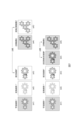
- FIG. 5A is a diagram schematically showing an example in which the conversion items are brightness, contrast, and noise
- FIG. 5B is a diagram schematically showing an example in which the conversion items are shading and shadow. be.
- FIGS. 5A (a1) to (a4) are examples when each of the conversion items of the conversion T and the inverse conversion U is brightness and contrast.
- the visual inspection system uniformizes and converts the apparent brightness and contrast on the learning image or input image (Fig. 5A (a1)) of the evaluation target, which changes depending on the imaging conditions, etc., to the standard value using the conversion T.
- An image h' is obtained (FIG. 5A (a2)).
- a process such as matching the brightness histogram of each image with a standard brightness histogram can be considered.
- processing for converting a color image into a grayscale image can also be considered.
- the visual inspection system performs inverse transformation U on the estimated image H' (5A(a3)) estimated by the estimation engine using the transformed image h' as input, and generates the inversely transformed estimated image H (5A(a4)) as an output image. do.
- FIGS. 5A (b1) to (b5) are examples in which each of the transformation items of the transformation T and the inverse transformation U is noise.
- the visual inspection system applies transformation T to the learning image or the input image (Fig. 5A (b1)) to equalize noise in these images and obtain a transformed image h' (5A (b2) ).
- Noise may be removed as shown in FIG. 5A (b2), or the noise level of each image may be adjusted to the reference noise amount. If noise is not required in the output image, the estimated image H' from which noise has been removed shown in FIG. 5A (b3) may be used as the output image.
- the visual inspection system can output the inversely transformed estimated image H shown in FIG. 5A (b4) in which noise is restored by the inversely transformed U.
- the inverse transformation U does not need to be a complete inverse transformation of the transformation T. That is, it is possible to change the degree (strength) of applying the inverse transformation U to the transformation T. For example, it would be unnatural if the noise completely disappeared from the output image, as shown in Figure 5A (b3), but it would be difficult to observe if the output image was superimposed with noise equivalent to the input image, as shown in Figure 5A (b4).
- the visual inspection system can restore a small amount of noise as shown in FIG. 5A (b5) by applying weight to the transformation U. This is not limited to noise, but the intensity can be adjusted for all conversion items.
- FIGS. 5B (c1) to (c5) are examples in which each transformation item of the transformation T and the inverse transformation U is shading.
- the visual inspection system applies transformation T to the learning image or input image (FIG. 5B (c1)) to equalize the shading of these images and obtain a transformed image h' (FIG. 5B (c2)). )).
- transformation T to the learning image or input image (FIG. 5B (c1)) to equalize the shading of these images and obtain a transformed image h' (FIG. 5B (c2)).
- FIG. 5B (d1) to (d4) are examples in which each transformation item of the transformation T and the inverse transformation U is shaded.
- the visual inspection system applies transformation T to the learning image or input image (FIG. 5B (d1)) to remove or equalize the shadows of these images and obtain a transformed image h' (FIG. 5B (d1)). (d2)). If a shadow is not necessary in the output image, the visual inspection system may directly use the estimated image H' from which the shadow has been removed, as shown in FIG. 5B (d3), as the output image. Alternatively, the visual inspection system may output the inversely transformed estimated image H shown in FIG. 5B (d4) in which noise is restored by the inversely transformed U.
- FIGS. 7(b1) to (b5) correspond to (2).
- the learning of the estimation engine basically involves adjusting the internal settings of the estimation engine, such as network weights and biases, so that the difference between the estimated image output from the estimation engine using the learning image as input and the correct image taught in advance is small. This is done by updating the parameters. Note that, as the difference between the estimated image and the correct image, for example, a difference in pixel data for each pixel of each image may be adopted.
- the visual inspection system performs a transformation T on the learning image f (FIG. 6(b1)), and transforms the transformed image f' (FIG. 6(b1)). 6(b2)) is obtained.
- the visual inspection system estimates an estimated image F' (FIG. 6(b3) or reference numeral 111 in FIG. 1) using an estimation engine using this converted image f' as input.
- the visual inspection system performs inverse transformation U (step S113 in FIG. 1) on the estimated image F' to obtain an inversely transformed estimated image F (FIG. 6(b4) or reference numeral 115 in FIG. 1).
- the visual inspection system calculates a loss value based on the difference between the inversely transformed estimated image F (FIG. 6 (b4)) and the correct image G (FIG. 6 (b5)), and uses an estimation engine to reduce the loss value.
- the learning image f, transformed image f', estimated image F', inversely transformed estimated image F, correct image G, and transformed correct image associated with that ID are displayed. Part or all of G' can be displayed in the image display area 803. In this way, by displaying not only the training image f, but also the transformed image f', estimated image F', inversely transformed estimated image F, correct image G, and transformed correct image G', the user can see what kind of processing has been done. can be known.
- Items that can be specified using the radio button 806 include "Automatically calculate reference value,” "Match to image with ID ⁇ ,” and "Specify reference value.” If the reference value is a position and "Automatically calculate reference value” is checked, the visual inspection system calculates, for example, the average position of the center positions of the plurality of input images f as the reference value. Furthermore, when “Match to image of ID ⁇ " is checked, the visual inspection system calculates the center position of the input image f associated with the specified ID " ⁇ " as a reference value. When “specify reference value” is checked, the visual inspection system displays a screen prompting the user to input a reference value, and adopts the value input by the user on the screen as the reference value.
- the purpose of the visual inspection system was to improve image quality by estimating a high-quality image from an input image, but the present invention is not limited to this.
- the purpose of the visual inspection system is image evaluation to estimate an evaluation value from an input image.
- the evaluation value in the case of visual inspection, the evaluation value is any of the inspection results such as the quality level, presence or absence of defects, degree of abnormality, and fatality of the evaluation target, and in the case of segmentation, the evaluation value is the label of the area.
- the evaluation value is the defect area.
- the visual inspection system is an example of an evaluation value estimation device, and executes an evaluation value estimation method.
- the evaluation value estimation method is a method executed by a computer, and includes a first learning image acquisition step of acquiring a plurality of learning images f of a learning object, and a conversion process to the plurality of learning images f. a first transformed image generation step of generating a plurality of transformed images f', a learning step of determining internal parameters of a machine learning-type estimation engine using the plurality of transformed images f', and a learning step of determining internal parameters of a machine learning-type estimation engine.
- FIG. 9 is a schematic diagram showing an example of the entire processing sequence performed by the visual inspection system according to the present embodiment.
- the processing sequence is broadly divided into a learning phase 900 and an operation phase 901.
- the visual inspection system images the evaluation target object 902 for learning to obtain a learning image f (904) (S903).
- a learning image f 904
- the user selects in advance which conversion items 907 are to be included in the conversion T (S905). For example, when the position of the evaluation object is included in the conversion item 907, the evaluation object existing at various positions in each learning image is shifted so that it exists at the same position (reference value) in all the learning images.
- the estimation engine estimates an estimated evaluation value P' (911) by inputting the transformed image f' (909) in which all evaluation objects are located at reference values. If transformation T is not performed, it is necessary to prepare a group of training images that cover the differences in the position of the evaluation target object for learning, but by performing transformation T, pattern variations related to the position of the evaluation target object are included in the training images. There will be no need.
- the visual inspection system causes a machine learning type estimation engine to learn the converted image f' and determines internal parameters 917 of the estimation engine (S910).
- the visual inspection system stores information on how each conversion item 907 was converted or the state before conversion for each input image h as a conversion parameter 923.
- the user selects the conversion item 914 necessary for the final output from among the conversion items of the conversion T (S912), and the second estimation is performed from the conversion parameter 923 and estimated evaluation value R' (921) for each selected conversion item.
- the evaluation value R (922) is estimated by the second estimation engine (S913). This second estimated evaluation value R becomes the output value of the image processing system.
- the conversion item 907 of conversion T is the position of the evaluation target object. If there is no need to handle the position of the evaluation object in step S920 in which the evaluation value is estimated using a machine learning estimation engine, the visual inspection system performs uniformization using transformation T. If the estimated evaluation value is the degree of abnormality of the evaluation target, and the criterion for the degree of abnormality handled by the estimation engine is a change in contrast in the input image of the evaluation target, then it is assumed that the image input to the estimation engine has positional variations. Doesn't need to be included.
- the position information excluded in the conversion T may also be taken into consideration. That is, if in addition to a change in contrast, a large positional shift of the evaluation target is also considered abnormal, the estimated evaluation value R' (911 ) and the position information included in the conversion parameter 923, the visual inspection system uses a second estimation engine to estimate a second estimated evaluation value R (922) (S913), and uses it as the final output value. .
- the second estimated evaluation value R can reflect any abnormalities such as contrast changes and positional deviations.
- FIG. 10 is a schematic diagram illustrating an example of a learning method of the estimation engine. There are two main learning methods: (1) and (2) below. Figures 10 (a1) to (a5) correspond to (1), and Figures 10 (b1) to (b5) correspond to (2). handle.
- the estimated evaluation value P' is estimated by the estimation engine using the transformed image f' as input.
- a correct value S' of the estimated evaluation value is estimated from the second correct evaluation value S and the conversion parameter. Internal parameters of the image estimation engine are determined based on the estimated evaluation value P' and the correct value S' of the estimated evaluation value.
- the learning of the estimation engine is performed using training images as input so that the difference between the estimated evaluation value output from the estimation engine and the correct evaluation value taught in advance (the correct value of the second estimated evaluation value) becomes small. This is done by updating internal parameters of the estimation engine, such as network weights and biases.
- step S910 the estimation engine estimates the degree of abnormality using criteria other than texture. For example, since a foreign object 1000 is attached to the converted image f' (FIG. 10(a2)), the degree of abnormality is estimated to be 45%.
- the degree of abnormality due to the foreign object alone is estimated to be, for example, 50% (FIG. 10 (a5)).
- the visual inspection device calculates a loss value based on the difference between the estimated evaluation value P' (FIG. 10 (a3)) and the correct value S' (FIG. 10 (a5)) of the estimated evaluation value, and calculates the loss value when the loss value is small. Determine the internal parameters of the estimation engine so that
- the second embodiment is different from the first embodiment in that the estimation value is changed from the image to the evaluation value, the conversion items, learning method, GUI, etc. are the same as the first embodiment.
- FIG. 11 is a hardware configuration diagram of each of the visual inspection systems of the first embodiment and the second embodiment.
- Storage resources 1102 examples include nonvolatile memories such as RAM (Random Access Memory), ROM (Read Only Memory), HDD (Hard Disk Drive), and flash memory.
- the storage resource may store a program that causes the processor 1101 to execute the image estimation method and evaluation value estimation method described in each of the above embodiments.
- the visual inspection system may include a plurality of computers 1100 and a plurality of imaging devices 1106.
- the program is distributed to the computer 1100 by the program distribution server.
- the program distribution server includes a storage resource that stores a program, a processor that performs distribution processing to distribute the program, and a communication interface device that can communicate with the communication interface device 1105 of the computer 1100.
- the present invention is not limited to the embodiments described above, and includes various modifications.
- each of the above-described embodiments has been described in detail to explain the present invention in an easy-to-understand manner, and the present invention is not necessarily limited to having all the components described.
- each of the above-mentioned configurations, functions, processing units, processing means, etc. may be partially or entirely realized by hardware, for example, by designing an integrated circuit.
- each of the above configurations, functions, etc. may be realized by software by a processor interpreting and executing a program for realizing each function.
- Information such as programs, judgment tables, files, etc. that realize each function is stored in memory, storage devices such as HDD, SSD, or recording media such as IC (Integrated Circuit) cards, SD (Secure Digital) cards, DVDs, etc. be able to.
- the control lines and information lines are shown to be necessary for explanation purposes, and not all control lines and information lines are necessarily shown in the product. In reality, almost all components may be considered to be interconnected.
Landscapes
- Engineering & Computer Science (AREA)
- Physics & Mathematics (AREA)
- General Physics & Mathematics (AREA)
- Theoretical Computer Science (AREA)
- Computer Vision & Pattern Recognition (AREA)
- Image Analysis (AREA)
- Image Processing (AREA)
Applications Claiming Priority (2)
| Application Number | Priority Date | Filing Date | Title |
|---|---|---|---|
| JP2022098864A JP7765351B2 (ja) | 2022-06-20 | 2022-06-20 | 画像推定方法、評価値推定方法、及び画像推定装置 |
| JP2022-098864 | 2022-06-20 |
Publications (1)
| Publication Number | Publication Date |
|---|---|
| WO2023248593A1 true WO2023248593A1 (ja) | 2023-12-28 |
Family
ID=89379535
Family Applications (1)
| Application Number | Title | Priority Date | Filing Date |
|---|---|---|---|
| PCT/JP2023/015216 Ceased WO2023248593A1 (ja) | 2022-06-20 | 2023-04-14 | 画像推定方法、評価値推定方法、及び画像推定装置 |
Country Status (2)
| Country | Link |
|---|---|
| JP (1) | JP7765351B2 (https=) |
| WO (1) | WO2023248593A1 (https=) |
Families Citing this family (1)
| Publication number | Priority date | Publication date | Assignee | Title |
|---|---|---|---|---|
| JP7633441B1 (ja) | 2024-02-01 | 2025-02-19 | 日本金銭機械株式会社 | 学習用データ生成装置、学習処理装置、画像データ生成装置、学習用データ生成方法、学習処理方法、画像データ生成方法、および、プログラム |
Citations (3)
| Publication number | Priority date | Publication date | Assignee | Title |
|---|---|---|---|---|
| JP2004062719A (ja) * | 2002-07-31 | 2004-02-26 | Fuji Xerox Co Ltd | 画像処理装置 |
| JP2016115313A (ja) * | 2014-12-18 | 2016-06-23 | 日本放送協会 | 超解像装置およびプログラム |
| JP2016177829A (ja) * | 2016-05-18 | 2016-10-06 | みずほ情報総研株式会社 | 情報予測システム、情報予測方法及び情報予測プログラム |
-
2022
- 2022-06-20 JP JP2022098864A patent/JP7765351B2/ja active Active
-
2023
- 2023-04-14 WO PCT/JP2023/015216 patent/WO2023248593A1/ja not_active Ceased
Patent Citations (3)
| Publication number | Priority date | Publication date | Assignee | Title |
|---|---|---|---|---|
| JP2004062719A (ja) * | 2002-07-31 | 2004-02-26 | Fuji Xerox Co Ltd | 画像処理装置 |
| JP2016115313A (ja) * | 2014-12-18 | 2016-06-23 | 日本放送協会 | 超解像装置およびプログラム |
| JP2016177829A (ja) * | 2016-05-18 | 2016-10-06 | みずほ情報総研株式会社 | 情報予測システム、情報予測方法及び情報予測プログラム |
Also Published As
| Publication number | Publication date |
|---|---|
| JP2024000211A (ja) | 2024-01-05 |
| JP7765351B2 (ja) | 2025-11-06 |
Similar Documents
| Publication | Publication Date | Title |
|---|---|---|
| US9773302B2 (en) | Three-dimensional object model tagging | |
| US9098893B2 (en) | System, method and computer program product for classification within inspection images | |
| JP5874398B2 (ja) | 画像検査装置の検査領域設定方法 | |
| JP7254324B2 (ja) | 画像検査システムの性能調整のための検査用画像を生成する画像生成装置及び画像生成方法 | |
| US11836961B2 (en) | Information processing apparatus, information processing method, and storage medium for determining whether a captured image of a subject is suitable for recognition processing | |
| US12499532B2 (en) | Computer and visual inspection method for identifying defective products | |
| US20130336575A1 (en) | System, method and computer program product for detection of defects within inspection images | |
| CN113807378B (zh) | 训练数据增量方法、电子装置与计算机可读记录介质 | |
| US9341579B2 (en) | Defect detection apparatus, defect detection method, and computer program | |
| CN108510440A (zh) | 用于将图像伪影最小化的超分辨率图像清晰化方法及装置 | |
| JPWO2010024402A1 (ja) | 画像処理装置および方法、ならびに、画像表示装置 | |
| JP2021165888A (ja) | 情報処理装置、情報処理装置の情報処理方法およびプログラム | |
| CN119295426B (zh) | 铝合金拉手表面缺陷检测方法、装置、设备及存储介质 | |
| WO2023248593A1 (ja) | 画像推定方法、評価値推定方法、及び画像推定装置 | |
| JP7070308B2 (ja) | 推定器生成装置、検査装置、推定器生成方法、及び推定器生成プログラム | |
| CN116824070B (zh) | 一种基于深度图像的实时三维重建方法及系统 | |
| JP2016057068A (ja) | パターン欠陥検査装置及びパターン欠陥検査方法 | |
| CN111699496B (zh) | 神经网络型图像处理装置、外观检查装置及外观检查方法 | |
| WO2024123989A1 (en) | Neural radiance field models with improved robustness against distractor objects | |
| CN116438569B (zh) | 数据创建系统、学习系统、估计系统、处理装置、评估系统、数据创建方法和程序 | |
| JP7623929B2 (ja) | システムおよびプログラム | |
| JP2007013231A (ja) | 画像のシェーディング補正装置、方法及びプログラム | |
| JP4857975B2 (ja) | 画像処理システムおよび画像処理プログラム | |
| Goring et al. | Appeal prediction for AI up-scaled Images | |
| JP7696451B2 (ja) | 欠陥診断モデル作成装置、欠陥診断モデル作成方法及び欠陥診断モデル作成プログラム |
Legal Events
| Date | Code | Title | Description |
|---|---|---|---|
| 121 | Ep: the epo has been informed by wipo that ep was designated in this application |
Ref document number: 23826782 Country of ref document: EP Kind code of ref document: A1 |
|
| NENP | Non-entry into the national phase |
Ref country code: DE |
|
| 122 | Ep: pct application non-entry in european phase |
Ref document number: 23826782 Country of ref document: EP Kind code of ref document: A1 |