WO2023248574A1 - 移動体給電システムおよび移動体装置 - Google Patents
移動体給電システムおよび移動体装置 Download PDFInfo
- Publication number
- WO2023248574A1 WO2023248574A1 PCT/JP2023/013839 JP2023013839W WO2023248574A1 WO 2023248574 A1 WO2023248574 A1 WO 2023248574A1 JP 2023013839 W JP2023013839 W JP 2023013839W WO 2023248574 A1 WO2023248574 A1 WO 2023248574A1
- Authority
- WO
- WIPO (PCT)
- Prior art keywords
- coil
- mobile device
- vector potential
- primary conductor
- vehicle
- Prior art date
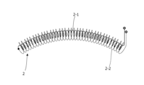
- Legal status (The legal status is an assumption and is not a legal conclusion. Google has not performed a legal analysis and makes no representation as to the accuracy of the status listed.)
- Ceased
Links
Images









Classifications
-
- B—PERFORMING OPERATIONS; TRANSPORTING
- B60—VEHICLES IN GENERAL
- B60L—PROPULSION OF ELECTRICALLY-PROPELLED VEHICLES; SUPPLYING ELECTRIC POWER FOR AUXILIARY EQUIPMENT OF ELECTRICALLY-PROPELLED VEHICLES; ELECTRODYNAMIC BRAKE SYSTEMS FOR VEHICLES IN GENERAL; MAGNETIC SUSPENSION OR LEVITATION FOR VEHICLES; MONITORING OPERATING VARIABLES OF ELECTRICALLY-PROPELLED VEHICLES; ELECTRIC SAFETY DEVICES FOR ELECTRICALLY-PROPELLED VEHICLES
- B60L53/00—Methods of charging batteries, specially adapted for electric vehicles; Charging stations or on-board charging equipment therefor; Exchange of energy storage elements in electric vehicles
- B60L53/10—Methods of charging batteries, specially adapted for electric vehicles; Charging stations or on-board charging equipment therefor; Exchange of energy storage elements in electric vehicles characterised by the energy transfer between the charging station and the vehicle
- B60L53/12—Inductive energy transfer
-
- B—PERFORMING OPERATIONS; TRANSPORTING
- B60—VEHICLES IN GENERAL
- B60M—POWER SUPPLY LINES, AND DEVICES ALONG RAILS, FOR ELECTRICALLY- PROPELLED VEHICLES
- B60M7/00—Power lines or rails specially adapted for electrically-propelled vehicles of special types, e.g. suspension tramway, ropeway, underground railway
-
- B—PERFORMING OPERATIONS; TRANSPORTING
- B60—VEHICLES IN GENERAL
- B60L—PROPULSION OF ELECTRICALLY-PROPELLED VEHICLES; SUPPLYING ELECTRIC POWER FOR AUXILIARY EQUIPMENT OF ELECTRICALLY-PROPELLED VEHICLES; ELECTRODYNAMIC BRAKE SYSTEMS FOR VEHICLES IN GENERAL; MAGNETIC SUSPENSION OR LEVITATION FOR VEHICLES; MONITORING OPERATING VARIABLES OF ELECTRICALLY-PROPELLED VEHICLES; ELECTRIC SAFETY DEVICES FOR ELECTRICALLY-PROPELLED VEHICLES
- B60L5/00—Current collectors for power supply lines of electrically-propelled vehicles
- B60L5/005—Current collectors for power supply lines of electrically-propelled vehicles without mechanical contact between the collector and the power supply line
-
- B—PERFORMING OPERATIONS; TRANSPORTING
- B60—VEHICLES IN GENERAL
- B60L—PROPULSION OF ELECTRICALLY-PROPELLED VEHICLES; SUPPLYING ELECTRIC POWER FOR AUXILIARY EQUIPMENT OF ELECTRICALLY-PROPELLED VEHICLES; ELECTRODYNAMIC BRAKE SYSTEMS FOR VEHICLES IN GENERAL; MAGNETIC SUSPENSION OR LEVITATION FOR VEHICLES; MONITORING OPERATING VARIABLES OF ELECTRICALLY-PROPELLED VEHICLES; ELECTRIC SAFETY DEVICES FOR ELECTRICALLY-PROPELLED VEHICLES
- B60L53/00—Methods of charging batteries, specially adapted for electric vehicles; Charging stations or on-board charging equipment therefor; Exchange of energy storage elements in electric vehicles
- B60L53/30—Constructional details of charging stations
- B60L53/32—Constructional details of charging stations by charging in short intervals along the itinerary, e.g. during short stops
-
- B—PERFORMING OPERATIONS; TRANSPORTING
- B60—VEHICLES IN GENERAL
- B60L—PROPULSION OF ELECTRICALLY-PROPELLED VEHICLES; SUPPLYING ELECTRIC POWER FOR AUXILIARY EQUIPMENT OF ELECTRICALLY-PROPELLED VEHICLES; ELECTRODYNAMIC BRAKE SYSTEMS FOR VEHICLES IN GENERAL; MAGNETIC SUSPENSION OR LEVITATION FOR VEHICLES; MONITORING OPERATING VARIABLES OF ELECTRICALLY-PROPELLED VEHICLES; ELECTRIC SAFETY DEVICES FOR ELECTRICALLY-PROPELLED VEHICLES
- B60L53/00—Methods of charging batteries, specially adapted for electric vehicles; Charging stations or on-board charging equipment therefor; Exchange of energy storage elements in electric vehicles
- B60L53/60—Monitoring or controlling charging stations
- B60L53/67—Controlling two or more charging stations
-
- B—PERFORMING OPERATIONS; TRANSPORTING
- B60—VEHICLES IN GENERAL
- B60L—PROPULSION OF ELECTRICALLY-PROPELLED VEHICLES; SUPPLYING ELECTRIC POWER FOR AUXILIARY EQUIPMENT OF ELECTRICALLY-PROPELLED VEHICLES; ELECTRODYNAMIC BRAKE SYSTEMS FOR VEHICLES IN GENERAL; MAGNETIC SUSPENSION OR LEVITATION FOR VEHICLES; MONITORING OPERATING VARIABLES OF ELECTRICALLY-PROPELLED VEHICLES; ELECTRIC SAFETY DEVICES FOR ELECTRICALLY-PROPELLED VEHICLES
- B60L58/00—Methods or circuit arrangements for monitoring or controlling batteries or fuel cells, specially adapted for electric vehicles
- B60L58/10—Methods or circuit arrangements for monitoring or controlling batteries or fuel cells, specially adapted for electric vehicles for monitoring or controlling batteries
- B60L58/18—Methods or circuit arrangements for monitoring or controlling batteries or fuel cells, specially adapted for electric vehicles for monitoring or controlling batteries of two or more battery modules
- B60L58/21—Methods or circuit arrangements for monitoring or controlling batteries or fuel cells, specially adapted for electric vehicles for monitoring or controlling batteries of two or more battery modules having the same nominal voltage
-
- H—ELECTRICITY
- H02—GENERATION; CONVERSION OR DISTRIBUTION OF ELECTRIC POWER
- H02J—ELECTRIC POWER NETWORKS; CIRCUIT ARRANGEMENTS OR SYSTEMS FOR SUPPLYING OR DISTRIBUTING ELECTRIC POWER; SYSTEMS FOR STORING ELECTRIC ENERGY
- H02J50/00—Circuit arrangements or systems for wireless supply or distribution of electric power
- H02J50/10—Circuit arrangements or systems for wireless supply or distribution of electric power using inductive coupling
-
- H—ELECTRICITY
- H02—GENERATION; CONVERSION OR DISTRIBUTION OF ELECTRIC POWER
- H02J—ELECTRIC POWER NETWORKS; CIRCUIT ARRANGEMENTS OR SYSTEMS FOR SUPPLYING OR DISTRIBUTING ELECTRIC POWER; SYSTEMS FOR STORING ELECTRIC ENERGY
- H02J50/00—Circuit arrangements or systems for wireless supply or distribution of electric power
- H02J50/10—Circuit arrangements or systems for wireless supply or distribution of electric power using inductive coupling
- H02J50/12—Circuit arrangements or systems for wireless supply or distribution of electric power using inductive coupling of the resonant type
-
- B—PERFORMING OPERATIONS; TRANSPORTING
- B60—VEHICLES IN GENERAL
- B60L—PROPULSION OF ELECTRICALLY-PROPELLED VEHICLES; SUPPLYING ELECTRIC POWER FOR AUXILIARY EQUIPMENT OF ELECTRICALLY-PROPELLED VEHICLES; ELECTRODYNAMIC BRAKE SYSTEMS FOR VEHICLES IN GENERAL; MAGNETIC SUSPENSION OR LEVITATION FOR VEHICLES; MONITORING OPERATING VARIABLES OF ELECTRICALLY-PROPELLED VEHICLES; ELECTRIC SAFETY DEVICES FOR ELECTRICALLY-PROPELLED VEHICLES
- B60L2200/00—Type of vehicles
- B60L2200/26—Rail vehicles
-
- B—PERFORMING OPERATIONS; TRANSPORTING
- B60—VEHICLES IN GENERAL
- B60L—PROPULSION OF ELECTRICALLY-PROPELLED VEHICLES; SUPPLYING ELECTRIC POWER FOR AUXILIARY EQUIPMENT OF ELECTRICALLY-PROPELLED VEHICLES; ELECTRODYNAMIC BRAKE SYSTEMS FOR VEHICLES IN GENERAL; MAGNETIC SUSPENSION OR LEVITATION FOR VEHICLES; MONITORING OPERATING VARIABLES OF ELECTRICALLY-PROPELLED VEHICLES; ELECTRIC SAFETY DEVICES FOR ELECTRICALLY-PROPELLED VEHICLES
- B60L2210/00—Converter types
- B60L2210/30—AC to DC converters
-
- B—PERFORMING OPERATIONS; TRANSPORTING
- B60—VEHICLES IN GENERAL
- B60L—PROPULSION OF ELECTRICALLY-PROPELLED VEHICLES; SUPPLYING ELECTRIC POWER FOR AUXILIARY EQUIPMENT OF ELECTRICALLY-PROPELLED VEHICLES; ELECTRODYNAMIC BRAKE SYSTEMS FOR VEHICLES IN GENERAL; MAGNETIC SUSPENSION OR LEVITATION FOR VEHICLES; MONITORING OPERATING VARIABLES OF ELECTRICALLY-PROPELLED VEHICLES; ELECTRIC SAFETY DEVICES FOR ELECTRICALLY-PROPELLED VEHICLES
- B60L2270/00—Problem solutions or means not otherwise provided for
- B60L2270/10—Emission reduction
- B60L2270/14—Emission reduction of noise
- B60L2270/147—Emission reduction of noise electro magnetic [EMI]
-
- H—ELECTRICITY
- H02—GENERATION; CONVERSION OR DISTRIBUTION OF ELECTRIC POWER
- H02J—ELECTRIC POWER NETWORKS; CIRCUIT ARRANGEMENTS OR SYSTEMS FOR SUPPLYING OR DISTRIBUTING ELECTRIC POWER; SYSTEMS FOR STORING ELECTRIC ENERGY
- H02J2105/00—Networks for supplying or distributing electric power characterised by their spatial reach or by the load
- H02J2105/30—Networks for supplying or distributing electric power characterised by their spatial reach or by the load the load networks being external to vehicles, i.e. exchanging power with vehicles
- H02J2105/33—Networks for supplying or distributing electric power characterised by their spatial reach or by the load the load networks being external to vehicles, i.e. exchanging power with vehicles exchanging power with road vehicles
- H02J2105/37—Networks for supplying or distributing electric power characterised by their spatial reach or by the load the load networks being external to vehicles, i.e. exchanging power with vehicles exchanging power with road vehicles exchanging power with electric vehicles [EV] or with hybrid electric vehicles [HEV]
-
- H—ELECTRICITY
- H02—GENERATION; CONVERSION OR DISTRIBUTION OF ELECTRIC POWER
- H02J—ELECTRIC POWER NETWORKS; CIRCUIT ARRANGEMENTS OR SYSTEMS FOR SUPPLYING OR DISTRIBUTING ELECTRIC POWER; SYSTEMS FOR STORING ELECTRIC ENERGY
- H02J50/00—Circuit arrangements or systems for wireless supply or distribution of electric power
- H02J50/005—Mechanical details of housing or structure aiming to accommodate the power transfer means, e.g. mechanical integration of coils, antennas or transducers into emitting or receiving devices
-
- H—ELECTRICITY
- H02—GENERATION; CONVERSION OR DISTRIBUTION OF ELECTRIC POWER
- H02J—ELECTRIC POWER NETWORKS; CIRCUIT ARRANGEMENTS OR SYSTEMS FOR SUPPLYING OR DISTRIBUTING ELECTRIC POWER; SYSTEMS FOR STORING ELECTRIC ENERGY
- H02J50/00—Circuit arrangements or systems for wireless supply or distribution of electric power
- H02J50/70—Circuit arrangements or systems for wireless supply or distribution of electric power involving the reduction of electric, magnetic or electromagnetic leakage fields
-
- H—ELECTRICITY
- H02—GENERATION; CONVERSION OR DISTRIBUTION OF ELECTRIC POWER
- H02J—ELECTRIC POWER NETWORKS; CIRCUIT ARRANGEMENTS OR SYSTEMS FOR SUPPLYING OR DISTRIBUTING ELECTRIC POWER; SYSTEMS FOR STORING ELECTRIC ENERGY
- H02J7/00—Circuit arrangements for charging or discharging batteries or for supplying loads from batteries
- H02J7/02—Circuit arrangements for charging or discharging batteries or for supplying loads from batteries for charging batteries from AC mains by converters
-
- H—ELECTRICITY
- H02—GENERATION; CONVERSION OR DISTRIBUTION OF ELECTRIC POWER
- H02M—APPARATUS FOR CONVERSION BETWEEN AC AND AC, BETWEEN AC AND DC, OR BETWEEN DC AND DC, AND FOR USE WITH MAINS OR SIMILAR POWER SUPPLY SYSTEMS; CONVERSION OF DC OR AC INPUT POWER INTO SURGE OUTPUT POWER; CONTROL OR REGULATION THEREOF
- H02M1/00—Details of apparatus for conversion
- H02M1/14—Arrangements for reducing ripples from DC input or output
-
- H—ELECTRICITY
- H02—GENERATION; CONVERSION OR DISTRIBUTION OF ELECTRIC POWER
- H02M—APPARATUS FOR CONVERSION BETWEEN AC AND AC, BETWEEN AC AND DC, OR BETWEEN DC AND DC, AND FOR USE WITH MAINS OR SIMILAR POWER SUPPLY SYSTEMS; CONVERSION OF DC OR AC INPUT POWER INTO SURGE OUTPUT POWER; CONTROL OR REGULATION THEREOF
- H02M7/00—Conversion of AC power input into DC power output; Conversion of DC power input into AC power output
- H02M7/02—Conversion of AC power input into DC power output without possibility of reversal
- H02M7/04—Conversion of AC power input into DC power output without possibility of reversal by static converters
- H02M7/06—Conversion of AC power input into DC power output without possibility of reversal by static converters using discharge tubes without control electrode or semiconductor devices without control electrode
-
- Y—GENERAL TAGGING OF NEW TECHNOLOGICAL DEVELOPMENTS; GENERAL TAGGING OF CROSS-SECTIONAL TECHNOLOGIES SPANNING OVER SEVERAL SECTIONS OF THE IPC; TECHNICAL SUBJECTS COVERED BY FORMER USPC CROSS-REFERENCE ART COLLECTIONS [XRACs] AND DIGESTS
- Y02—TECHNOLOGIES OR APPLICATIONS FOR MITIGATION OR ADAPTATION AGAINST CLIMATE CHANGE
- Y02T—CLIMATE CHANGE MITIGATION TECHNOLOGIES RELATED TO TRANSPORTATION
- Y02T10/00—Road transport of goods or passengers
- Y02T10/60—Other road transportation technologies with climate change mitigation effect
- Y02T10/70—Energy storage systems for electromobility, e.g. batteries
Definitions
- the present invention relates to a mobile power supply system and a mobile device.
- multiple primary coils are embedded in the road at predetermined intervals, a secondary coil is installed in the vehicle, and when the vehicle (secondary coil) passes over the primary coil, the primary coil and the secondary coil are Electric power is supplied from the primary coil to the vehicle (secondary coil) by electromagnetic coupling of the coils (for example, see Patent Document 1).
- an AC vector potential detection device using a vector potential coil formed by winding a solenoid coil in an annular shape has been developed (see, for example, Patent Document 2).
- a shield penetration device has been developed that utilizes the property that a vector potential passes through an electromagnetic shield (see, for example, Patent Document 3).
- the present invention has been made in view of the above problems, and provides a mobile power supply system that realizes power supply to a mobile device at a relatively low cost, and a mobile device that can be used in the mobile power supply system.
- the purpose is to
- the mobile power supply system includes a primary conductor through which an alternating current is conducted, and a vector potential generated by the alternating current flowing through the primary conductor, which is sensed in a non-contact manner, and a current generated from a voltage difference due to the vector potential. and a mobile device equipped with a vector potential coil that conducts.
- the primary conductor is a part or all of a conductive wire that is continuously arranged along the moving path of the mobile device, and the vector potential coil is a vector potential coil that continuously moves the vector potential coil when the mobile device is on the moving path. Senses potential without contact and conducts current.
- a mobile device non-contactly generates a vector potential generated by an alternating current flowing through a primary conductor that is part or all of a conductor that is continuously arranged along a moving path of the mobile device. It is equipped with a vector potential coil that conducts the current generated from the voltage difference due to the vector potential sensed by the vector potential coil.
- the vector potential coil continuously senses vector potential in a non-contact manner and conducts current when the mobile device is on a moving route.
- the present invention it is possible to obtain a mobile power supply system that realizes power supply to a mobile device at a relatively low cost, and a mobile device that can be used in the mobile power supply system.
- FIG. 1 is a perspective view showing an example of a mobile power supply system according to Embodiment 1 of the present invention.
- FIG. 2 is a perspective view illustrating a primary conductor and a vector potential coil in the mobile power supply system shown in FIG.
- FIG. 3 is a diagram illustrating a change in power receiving efficiency with respect to a positional shift of the power receiving side with respect to the power transmitting side in a verification experiment.
- FIG. 4 is a block diagram showing an example of the electrical configuration of the mobile power supply system shown in FIG. 1.
- FIG. 5 is a diagram showing an example of a plurality of primary conductors along a multi-lane road in the mobile power supply system shown in FIG. FIG.
- FIG. 6 is a diagram showing an example of a meandering primary conductor on a road in an urban area in the mobile power supply system shown in FIG.
- FIG. 7 is a diagram showing an example of a primary conductor in a parking lot in the mobile power supply system shown in FIG. 1.
- FIG. 8 is a cross-sectional view showing an example of the arrangement of vector potential coils 2 in a mobile device according to Embodiment 2 of the present invention.
- FIG. 9 is a sectional view showing another example of the arrangement of the vector potential coil 2 in the mobile device according to the second embodiment of the present invention.
- FIG. 10 is a side view showing an example of a mobile power supply system according to Embodiment 3 of the present invention.
- FIG. 11 is a front view showing an example of the installation position of the vector potential coil in the third embodiment.
- FIG. 12 is a front view showing an example of the vector potential coil 2 and the ferromagnetic member 2A in the mobile device according to the fourth embodiment.
- FIG. 13 is a front view showing an example of the vector potential coil 2 and the ferromagnetic member 2B in the mobile device according to the fifth embodiment.
- FIG. 14 is a front view showing an example of the vector potential coil 2 in the mobile device according to the sixth embodiment.
- FIG. 15 is a front view showing an example of the vector potential coil 2 and the ferromagnetic member 2C in the mobile device according to the seventh embodiment.
- FIG. 16 is a front view showing an example of the vector potential coil 2 and the ferromagnetic member 2D in the mobile device according to the eighth embodiment.
- FIG. 17 is a front view showing an example of the vector potential coil 2 in the mobile device according to the ninth embodiment.
- FIG. 18 is a top view showing an example of the vector potential coil 2 in the mobile device according to the tenth embodiment.
- FIG. 19 is a circuit diagram illustrating a resonant circuit in a mobile device according to Embodiment 11.
- FIG. 20 is a diagram showing simulation results of the output voltage of the power supply device 6 in the eleventh embodiment.
- FIG. 1 is a perspective view showing an example of a mobile power supply system according to Embodiment 1 of the present invention.
- the mobile power supply system shown in FIG. 1 includes a primary conductor 1 and a vehicle 101 equipped with a vector potential coil 2, and supplies power from the primary conductor 1 to the vector potential coil 2 using vector potential.
- the vehicle 101 is a type of mobile device that moves on a road 102 as a travel route, and in this case is an electric vehicle.
- the vector potential coil (hereinafter also referred to as VP coil) 2 non-contactly senses the vector potential generated by the alternating current flowing through the primary conductor 1, and conducts the current (alternating current) induced by the vector potential. Note that even if the vehicle 101 is not running and is stopped, if an alternating current is conducted through the primary conductor 1, the above-mentioned alternating current is induced in the VP coil 2.
- the primary conductor 1 is part or all of a (non-wound) conductive wire that is continuously arranged along a travel path of the mobile device (here, a road 102 on which the vehicle 101 can pass).
- the primary conductor 1 has a linear or curved shape depending on the shape of the road 102.
- the primary conductor 1 is buried at a predetermined depth D in the center of a road 102 (lane).
- a coated conducting wire is used as the primary conductor 1, and is insulated from the ground.
- the VP coil 2 continuously senses the vector potential in a non-contact manner and conducts current when the vehicle 101 (mobile device) is on the moving route (here, the road 102 where the primary conductor 1 is installed). .
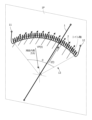
- FIG. 2 is a perspective view illustrating the primary conductor 1 and vector potential coil 2 in the mobile power supply system shown in FIG. 1.
- the VP coil 2 is a solenoid coil extending along a curved coil axis, and the primary conductor 1 is positioned inward of the curve of the coil axis. It is arranged so that Further, the VP coil 2 is arranged such that the coil axis (the winding center line of the VP coil 2) extends within a plane 1P perpendicular to the primary conductor 1.
- the shape of the coil axis is an open curve, and the shape is such that the angle seen from the primary conductor 1 at each position of the coil axis from one end of the VP coil 2 to the other end monotonically increases or decreases. has. Therefore, in the direction of the inside of the curve, the VP coil 2 forms an opening 13 .
- the shape of the coil axis is preferably an arc with the primary conductor 1 (that is, the alternating current flowing through the primary conductor 1) as the center, and the primary conductor 1 is preferably formed at the center of curvature of the coil axis.
- the VP coil 2 is arranged in such a manner that the VP coil 2 is arranged as shown in FIG. Therefore, the curvature (radius of curvature) of the coil axis may be set depending on the buried depth D of the primary conductor 1 and the installation height of the VP coil 2 from the road surface of the road 102.
- the VP coil 2 is placed close to the alternating current (that is, the primary conductor 1), for example, the VP coil 2 is placed at a position of 1 m or less, or 0.5 m or less from the primary conductor 1.
- the VP coil 2 is installed in the vehicle 101 so as to be arranged.
- the central angle ⁇ of the circular arc of the coil shaft (the central angle of a fan shape with the circular arc as the outer periphery) is 180 degrees or less. Since the sensed vector potential increases in proportion to this central angle ⁇ , it is preferable that this central angle ⁇ is large.
- This central angle ⁇ is any angle greater than 0 degrees and less than 360 degrees, and may also be (a) any angle greater than 0 degrees and less than 180 degrees, and (b) less than 0 degrees. (c) may be any angle greater than 0 degrees and less than 45 degrees; or (d) greater than 0.5 degrees and 360 degrees. Furthermore, (e) it may be any angle between 0.5 degrees and 180 degrees, and (f) 0.5 degrees and above and 90 degrees.
- angles It may be any of the following angles: (e) It may be any angle between 0.5 degrees and 45 degrees; (f) Any angle between 0.5 degrees and 25 degrees. or (g) any angle greater than or equal to 2 degrees and less than 360 degrees; and (h) any angle greater than or equal to 2 degrees and less than 180 degrees. (i) Any angle between 2 degrees and 90 degrees; (j) Any angle between 2 degrees and 45 degrees.
- (k) may be any angle greater than or equal to 25 degrees, or (l) may be any angle greater than or equal to 5 degrees and less than 360 degrees; (m) It may be any angle of 5 degrees or more and 180 degrees or less, (n) It may be any angle of 5 degrees or more and 90 degrees or less, (o) 5 degrees or more and (p) may be any angle of 45 degrees or less, or (p) may be any angle of 5 degrees or more and 25 degrees or less.
- an ideal curve is an arc that is part of a circle, but due to manufacturing and layout considerations, it does not necessarily have to be an arc, and any smooth curved shape is sufficient. If the primary conductor 1 is placed in the concave (inward) direction, a relatively large vector potential can be sensed.
- the alternating current induced in the VP coil 2 will be explained.
- the intensity of the vector potential VP(t) decreases in inverse proportion to the distance from the primary conductor 1.
- the time differential of the vector potential VP(t) is proportional to the electric field, and the result of line integration of the electric field along the winding path is the induced voltage. Therefore, in the VP coil 2, a high voltage is generated in the part close to the primary conductor 1, and a low voltage is generated in the part far from the primary conductor 1. Since they are in phase, the difference in voltage between the two becomes an induced voltage. , if the number of turns of the VP coil 2 is increased, a proportional voltage will be generated. Therefore, an alternating current is induced in the VP coil 2 as the vector potential VP(t) due to the alternating current I(t) of the primary conductor 1 changes over time.
- the induced voltage of the vector potential is not attenuated by electromagnetic shielding, so even if the body and chassis of the vehicle 101 have magnetic shielding properties, the AC of the primary conductor 1 An alternating current is induced in the VP coil 2 as the vector potential due to the current changes over time.
- This equation is a relational equation of magnetic flux ⁇ , B is the magnetic flux density, and ⁇ A is the rotation of the vector potential A.
- the last term is based on Stokes' theorem, and magnetic flux can be expressed as a vector potential.
- This equation expresses Faraday's electromagnetic induction using magnetic flux as a vector potential.
- Faraday's electromagnetic induction states that when the magnetic flux inside a coil changes over time, a proportional voltage is generated.
- the minus sign refers to Lenz's law, which states that voltage is generated in a direction that prevents changes in magnetic flux.
- the magnetic flux is expressed as a vector potential, it becomes a circuit integral using the above-mentioned relational expression of the magnetic flux ⁇ , and the circuit integral is a closed line integral.
- the integral path does not necessarily have to be closed, and a voltage is generated according to the length of the integral path of the line integral (in other words, it is not a circular integral, but an angle from 0 to ⁇ ).
- the voltage of that part is given by the line integral that does not go around (does not go around once). That is, even if there is an opening 13 in the integral path, a voltage is generated. Therefore, even if there is no magnetic flux inside the coil, if a vector potential is induced, voltage can be induced.
- ⁇ is the central angle of the circular arc formed by the coil axis. For example, when ⁇ is ⁇ , the output voltage V 2 becomes half of that of one round.
- the following equation is a theoretical equation for determining the open circuit voltage generated across the VP coil 2 from the current flowing through the primary conductor 1, depending on the shape parameters of the vector potential convergence coil and the characteristics of the magnetic material.
- the VP coil 2 has an arc shape, and the primary conductor 1 is located at the center of the circle including the arc.
- V2 is the output voltage of VP coil 2
- N is the number of winding layers of VP coil 2
- r is the winding coil radius of VP coil 2
- d is the diameter of the coil wire of VP coil 2.
- R is the bending radius of the VP coil 2
- I0 is the current amplitude of the primary conductor 1
- ⁇ is the angular frequency of the above-mentioned alternating current
- ⁇ 0 is the vacuum permeability
- ⁇ re is the strength coefficient described later.
- It is the effective relative permeability of the magnetic material member
- ⁇ is the arc angle (center angle) of the VP coil 2 (0 ⁇ 360 [deg])
- k is the winding gap ratio
- t is the time. .
- the inventors conducted a verification experiment using the VP coil 2 and a conventional spiral coil. Specifically, for the VP coil 2, an alternating current of 5 A and 20 kHz was conducted through the linear conductor part (primary conductor 1), and the other conductor parts were electromagnetically shielded with a 2 mm thick steel pipe. , when the VP coil 2 (center angle: approximately 180 degrees) is arranged parallel to the vertical plane of the straight conductor part, and there is a 5 mm thick iron plate between the VP coil 2 and the straight conductor part. The output power of the VP coil 2 was measured for the cases where the VP coil 2 and the VP coil 2 were not provided.
- the spiral coil on the power transmitting side and the spiral coil on the power receiving side are arranged so as to face each other, and an alternating current of 5 A and 20 kHz is conducted to the spiral coil on the power transmitting side, and the spiral coil on the power receiving side The output power of the spiral coil was measured.
- the vehicle 101 is made of a member having magnetic shielding properties (steel, stainless steel, etc.), and the VP coil 2 is disposed within the vehicle 101.
- the load resistance connected to the receiving coil was set to 0.15 ⁇ when a similar iron plate was inserted between the transmitting coil and the receiving coil, and when it was not inserted.
- the output power of the receiving coil was measured by varying the resistance up to 1.00 ⁇ .
- the output power of the power-receiving coil with the iron plate shield was below the measurement limit of the measuring instrument used, and the power transmittance was approximately 0%.
- FIG. 3 is a diagram illustrating changes in power receiving efficiency with respect to positional deviation of the power receiving side relative to the power transmitting side in a verification experiment.
- the plane perpendicular to the primary conductor 1 is the XY plane, and the primary conductor 1 is aligned along the Z axis.
- the VP coil is placed at the origin (0,0) of the XY plane, with both ends of the VP coil 2 aligned in the X-axis direction, and the plane containing the coil axis of the VP coil 2 being parallel to the XY plane.
- the plane perpendicular to the winding surface of the power transmitting coil is taken as the XY plane, and the center of the power transmitting coil is placed at the origin (0,0) of the XY plane.
- the ratio power receiving efficiency
- FIG. 3 uses contour lines to express the distribution of power receiving efficiency with respect to the positional deviation of the VP coil 2 and the distribution of the power receiving efficiency with respect to the positional deviation of the spiral coil. As shown in FIG. 3, for the VP coil 2, even if a positional shift occurs, the power receiving efficiency decreases relatively little. That is, in the case of the VP coil 2, for example, even if the position of the moving body on which the VP coil 2 is installed is shifted from the primary conductor 1, the power reception efficiency remains relatively unchanged.
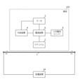
- FIG. 4 is a block diagram showing an example of the electrical configuration of the mobile power supply system shown in FIG. 1.
- the vehicle 101 includes, in addition to the above-mentioned VP coil 2, an internal device 4 including an electrical system such as a motor 3 that drives the wheels, a controller for the motor 3, a secondary battery unit 5, and a power supply device 6. Equipped with. Further, as infrastructure, a primary conductor 1 is laid, and a power distribution device 1A that conducts the above-mentioned alternating current to the primary conductor 1 is installed. The power distribution device 1A conducts an alternating current at a predetermined frequency and a predetermined amplitude. For example, the primary conductor 1 and the power distribution device 1A may be provided for each road link, or may be provided for each predetermined distance.
- the secondary battery unit 5 includes one or more secondary battery modules that store drive power for the motor 3.
- the power supply device 6 supplies power to the motor 3, internal device 4, secondary battery unit 5, etc. based on the current induced in the VP coil 2.
- the power supply device 6 includes an AC/DC converter circuit and a charging circuit for the secondary battery unit 5, and converts the AC power induced in the VP coil 2 into DC power with the AC/DC converter circuit, and converts the AC power induced in the VP coil 2 into DC power with the charging circuit.
- the secondary battery unit 5 may be charged based on the DC power, and the DC power and/or the power stored in the secondary battery unit 5 may be supplied to the motor 3, internal device 4, etc.
- the VP coil 2 may be one solenoid coil, or the VP coil 2 may be a plurality of solenoid coils.
- the plurality of VP coils 2 are electrically connected in series or in parallel as necessary.
- the plurality of VP coils 2 may be arranged horizontally or vertically.
- the power supply device 6 is provided with a plurality of AC/DC converter circuits for the plurality of VP coils 2, and the outputs of the plurality of AC/DC converter circuits are connected in series or in parallel, and the outputs are connected in series or in parallel. Electric power may be supplied to the motor 3, internal device 4, and secondary battery unit 5.
- FIG. 5 is a diagram showing an example of a plurality of primary conductors 1 along a multi-lane road in the mobile power supply system shown in FIG. 1.
- the primary conductor 1-1A, 1-1B, 1-2A, and 1-2B are arranged in each of the plurality of lanes 111A, 111B, 112A, and 112B. Further, the primary conductors 1-1A, 1-1B, 1-2A, and 1-2B are arranged in parallel with each other.
- any two of the primary conductors 1-1A, 1-1B, 1-2A, and 1-2B are approximately close to each other at each point. They are arranged at equal intervals. Part or all of the primary conductors 1-1A, 1-1B, 1-2A, and 1-2B are electrically connected in series or in parallel as necessary. Furthermore, alternating currents I1(t), I2(t), I3(t), and I4(t) at the same frequency are applied to the primary conductors 1-1A, 1-1B, 1-2A, and 1-2B are electrically connected in a forward direction (a predetermined direction) or a reverse direction (a direction opposite to a predetermined direction).
- alternating currents I1(t), I2(t), I3(t), and I4(t) the sum of alternating currents I1(t) and I3(t) conducting in the forward direction and the sum of alternating currents I1(t) and I3(t) conducting in the reverse direction.
- the direction and amplitude of each current are set so that the difference from the sum of alternating currents I2(t) and I4(t) is approximately zero.
- the magnetic field caused by the alternating current that conducts in the forward direction and the magnetic field caused by the alternating current that conducts in the opposite direction have opposite phases to each other, suppressing magnetic fields and EMC (Electromagnetic Compatibility) noise to the outside (surrounding area, etc.) .
- EMC Electromagnetic Compatibility
- the road 102 has an odd number (three in this case) of lanes 111A, 111B, 112, and the primary conductors 111A, 111B, 112 are laid in parallel to each other. Even if the AC currents I5(t), I6(t), and I7(t) of those lanes 111A, 111B, and 112 are connected in the forward direction, The direction and amplitude of each current are set so that the difference between the current I7(t) and the sum of the alternating currents I7(t) conducting in the opposite direction is approximately zero. As a result, the magnetic field caused by the alternating current that conducts in the forward direction and the magnetic field caused by the alternating current that conducts in the opposite direction have opposite phases to each other, so that the magnetic field and EMC noise to the outside are suppressed.
- the difference between the sum of the AC currents conducting in the forward direction and the sum of the AC currents conducting in the reverse direction is the same, regardless of the number of lanes on the road 102.
- the alternating currents in two lanes adjacent to each other may be in phase with each other or may be in phase with each other.
- FIG. 6 is a diagram showing an example of a meandering primary conductor 1 on a road in an urban area in the mobile power supply system shown in FIG. 1.
- roads 102 in an urban area, there are roads 102 in a substantially grid shape around a plurality of buildings 103, and meandering primary conductors 1 are laid on the roads 102, as shown in FIG. 6, for example. That is, in this case, the primary conductor 1 has a shape such that an alternating current is conducted in a meandering manner.
- FIG. 7 is a diagram showing an example of the primary conductor 1 in a parking lot in the mobile power supply system shown in FIG. 1.
- the above-mentioned travel path includes one or more parking spaces for the vehicle 101 in the parking lot, for example, as shown in FIG.
- the center of each parking space 201A is laid along the direction of the parked vehicle (parked vehicle 101). As a result, power is supplied to the parked vehicle 101.
- the power distribution device 1A conducts an alternating current to the primary conductor 1 laid along the travel route (road 102, parking space 201A, etc.). A magnetic field and vector potential based on this alternating current are generated around the primary conductor 1 (on the road 102, on the parking space 201A, etc.).
- the alternating current I(t) flowing through the primary conductor 1 causes a time-varying vector to be placed at the installation position of the VP coil 2.
- a potential VP(t) is generated, and an alternating current is induced in the VP coil 2 by this time-varying vector potential VP(t).
- the power supply device 6 converts AC power based on the AC current induced in the VP coil 2 into DC power, and supplies the DC power to the motor 3, internal device 4, secondary battery unit 5, etc. In addition, during a period when sufficient power is not obtained from the VP coil 2 (such as when driving in a section where the primary conductor 1 is not installed), the power supply device 6 uses the power obtained from the secondary battery unit 5 to power the motor. 3 and internal device 4.
- an alternating current is conducted through the primary conductor 1, and the vehicle 101 as a mobile device is equipped with the VP coil 2.
- the vector potential generated by the alternating current flowing through the conductor 1 is sensed without contact, and the current induced by the vector potential is made conductive.
- the primary conductor 1 is a part or all of a conductive wire that is continuously arranged along a road 102, a parking space 201A, etc. as a travel route of the mobile device, and the VP coil 2 is a When a vehicle 101 is on a road 102 as a moving route, a parking space 201A, etc., vector potential is continuously sensed in a non-contact manner and current is conducted.
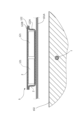
- FIG. 8 is a cross-sectional view showing an example of the arrangement of vector potential coils 2 in a mobile device according to Embodiment 2 of the present invention.
- FIG. 9 is a sectional view showing another example of the arrangement of the vector potential coil 2 in the mobile device according to the second embodiment of the present invention.
- the VP coil 2 is installed together with the secondary battery unit 5 on the undercarriage of the vehicle 101 or at the bottom 101A of the body (inside the body). (on top of the body bottom 101A). Since the secondary battery unit 5 for motive power in the vehicle 101 (electric vehicle) is heavy, the secondary battery unit 5 is normally installed on the chassis or body bottom 101A of the vehicle 101.
- the VP coil 2 is arranged along the outer shape of the secondary battery unit 5 at least on the upper surface of the secondary battery unit 5.
- the VP coil 2 is arranged on the top surface and side surface of the secondary battery unit 5.
- the VP coil 2 may be arranged within the thickness of the case 122 of the power storage member 121 in the secondary battery unit 5.
- the case 122 includes a lower container 122A and a lid 122B, and is disposed within the thickness of one or both of the lower container 122A and the lid 122B.
- the VP coil 2 is arranged so that the coil axis (the winding center line of the VP coil 2) extends within a plane 1P perpendicular to the primary conductor 1.
- Embodiment 2 Note that the other configurations and operations of the mobile device and mobile power supply system according to Embodiment 2 are the same as in Embodiment 1, so the description thereof will be omitted.
- the VP coil 2 is placed near the primary conductor 1 because the VP coil 2 is arranged on the vehicle chassis or the bottom part 101A of the body together with the relatively heavy secondary battery unit 5.
- the power supply device 6 together with the VP coil 2 in the secondary battery unit 5
- the wiring between the VP coil 2 and the power supply device 6 and the wiring between the power supply device 6 and the secondary battery unit 5 can be simplified. Becomes shorter.
- FIG. 10 is a side view showing an example of a mobile power supply system according to Embodiment 3 of the present invention.
- the mobile device is a locomotive or a train
- the movement route is a track
- the primary conductor has a linear or curved shape depending on the shape of the track. has.
- the primary conductor is an overhead wire 301 such as a trolley wire
- the mobile device is an electric train 302.
- the primary conductor (overhead wire 301) may be a covered conductor instead of a bare wire such as a trolley wire.
- the electric train 302 has the same electrical configuration (FIG. 4) as the vehicle 101 described above.
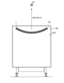
- FIG. 11 is a front view showing an example of the installation position of the vector potential coil 2 in the third embodiment.
- the VP coil 2 is arranged on the end wall 302B of the train 302.
- the VP coil 2 is installed inside the end wall 302B, but the VP coil 2 may be installed outside the end wall 302B.
- the VP coil 2 is similar to that in the first embodiment, and is a solenoid coil extending along a curved coil axis, as shown in FIG. 301 (primary conductor) is arranged so as to be located inward of the curve of the coil axis. Further, the VP coil 2 is arranged so that the coil axis (the winding center line of the VP coil 2) extends within a plane perpendicular to the overhead wire 301.
- the shape of the coil shaft is preferably an arc with the overhead wire 301 (that is, the alternating current flowing through the overhead wire 301) as the center, and the VP is arranged such that the overhead wire 301 is placed at the center of curvature of the coil shaft.
- a coil 2 is arranged. Therefore, the curvature (radius of curvature) of the coil axis may be set according to the installation height of the VP coil 2.
- the VP coil 2 is preferably placed close to the alternating current (that is, the overhead wire 301), for example, the VP coil 2 is placed at a position 2 m or less, or 1 m or less from the overhead wire 301.
- the VP coil 2 with a curved coil axis is used here, one or more VP coils 2 (described later) with a straight coil axis may be used instead. In that case, the VP coil 2 may be placed outside or inside the roof of the train 302.
- the body of the electric train 302 may be composed of magnetically shielding members (a roof made of steel, stainless steel, etc., a gable wall, a side wall, etc.), and the VP coil 2 is made of such a member. It may be placed inside a building frame.
- Embodiment 3 the other configurations and operations of the mobile device and the mobile power supply system according to Embodiment 3 are the same as those in Embodiment 1 or 2, and therefore their description will be omitted. Further, here, the VP coil 2 is provided in the electric train 302, but the same applies to a locomotive.
- the third embodiment as in the first embodiment, it is sufficient to continuously lay the primary conductor 1 along the track (a route on which a rail or the like is laid), and the power supply Since it is not necessary to arrange a large number of power supply coils on the primary side of the mobile device, power can be supplied to the mobile device (here, the train 302, etc.) at a relatively low cost.
- FIG. 12 is a front view showing an example of the vector potential coil 2 and the ferromagnetic member 2A in the mobile device (the above-mentioned vehicle 101, electric train 302, etc.) according to the fourth embodiment.
- a ferromagnetic member 2A is arranged inside the VP coil 2.
- This ferromagnetic member 2A has a shape along the coil axis of the VP coil 2.
- the ferromagnetic member 2A is a member made of a conductive ferromagnetic material (for example, a metal magnetic material such as permalloy), and one coil of the VP coil 2 is attached to one end 2A1 of the ferromagnetic member 2A. The ends are electrically connected.
- two wires from the other coil end of the VP coil 2 and the other end of the ferromagnetic member 2A adjacent to the other coil end to the power supply device 6 can be laid together. It becomes easy to install two wires.
- the VP coil 2 is formed by winding a thin copper wire around a thick ferromagnetic wire as the ferromagnetic member 2A formed in an arc shape. As shown in FIG. 12, one end of this thin copper wire is electrically connected to the ferromagnetic member 2A (end portion 2A1), and the other end is connected to one terminal.
- the ferromagnetic member 2A also serves as a current return path and is connected to the other terminal.
- a paramagnetic member having a similar shape may be used instead of the ferromagnetic member 2A.
- the vector potential is enhanced according to the effective magnetic permeability.
- Embodiment 4 Note that the other configurations and operations of the mobile device according to Embodiment 4 are the same as in any of Embodiments 1 to 3, so their explanations will be omitted.
- FIG. 13 is a front view showing an example of the vector potential coil 2 and the ferromagnetic member 2B in the mobile device (the above-mentioned vehicle 101, electric train 302, etc.) according to the fifth embodiment.
- a ferromagnetic member 2B is arranged inside the VP coil 2.
- the ferromagnetic member 2B has a shape along the coil axis of the VP coil 2, and further extends outside the curve of the VP coil 2 (the coil axis portion of the VP coil 2) to form a closed magnetic path. There is.
- the ferromagnetic member 2B is a member made of a conductive ferromagnetic material (for example, a metal magnetic material such as permalloy), and is connected to one coil of the VP coil 2 at a connection point 2B1 on one coil end side of the VP coil 2. The end is electrically connected to the ferromagnetic member 2B.
- a conductive ferromagnetic material for example, a metal magnetic material such as permalloy
- a lead wire is electrically connected at the connection point 2B2 on the other coil end side of the VP coil 2, and two wires are connected from the other coil end of the VP coil 2 and the lead wire to the power supply device 6. can be laid all at once, making it easy to lay two wires.
- a gap 2B3 is formed in the ferromagnetic member 2B on the outside of the curve of the VP coil 2, and the gap 2B3 allows current to pass through the portion of the ferromagnetic member 2B outside the curve of the VP coil 2. It is no longer conductive.
- the transition part between the inner part and the outer part of the ferromagnetic member 2B is made continuous and smooth without any sharp bends in order to reduce the influence of magnetic flux leakage or decrease in magnetic permeability due to bending. It is preferable to have a curved shape. Further, the ferromagnetic member 2B may be formed by connecting a plurality of members.
- Embodiment 5 Note that the other configurations and operations of the mobile device according to Embodiment 5 are the same as in Embodiment 4, so their explanations will be omitted.
- FIG. 14 is a front view showing an example of the vector potential coil 2 in the mobile device (the above-mentioned vehicle 101, train 302, etc.) according to the sixth embodiment.
- the VP coil 2 includes an inner solenoid coil 2-1 and an outer solenoid coil 2-2, which have the same coil axis and have different coil diameters.
- One coil end of the coil 2-1 and one coil end of the outer solenoid coil 2-2 are electrically connected.
- the inner solenoid coil 2-1 and the outer solenoid coil 2-2 each function as one VP coil. Therefore, the VP coil 2 of the sixth embodiment electrically functions as two VP coils.
- the configuration is such that they are connected in series in the same phase.
- the inner solenoid coil 2-1 and the outer solenoid coil 2-2 are arranged so that the vector potential and magnetic field generated by the inner solenoid coil 2-1 and the vector potential and magnetic field generated by the outer solenoid coil 2-2 are in the same direction. It is wound and connected as follows.
- Embodiment 6 Note that the other configurations and operations of the mobile device according to Embodiment 6 are the same as in any of Embodiments 1 to 3, and therefore their descriptions will be omitted.
- FIG. 15 is a front view showing an example of the vector potential coil 2 and the ferromagnetic member 2C in the mobile device (the above-mentioned vehicle 101, electric train 302, etc.) according to the seventh embodiment.
- the VP coil 2 includes an inner solenoid coil 2-1 and an outer solenoid coil 2-2 similar to those in the sixth embodiment. Furthermore, in the seventh embodiment, as shown in FIG. 15, for example, a ferromagnetic member 2C is arranged inside the VP coil 2 (inner solenoid coil 2-1). This ferromagnetic member 2C is similar to the above-described ferromagnetic member 2A. However, the VP coil 2 and the ferromagnetic member 2C are not electrically connected, and the ferromagnetic member 2C does not need to have electrical conductivity.
- Embodiment 7 Note that the other configurations and operations of the mobile device according to Embodiment 7 are the same as in Embodiment 6, so their explanations will be omitted.
- FIG. 16 is a front view showing an example of the vector potential coil 2 and the ferromagnetic member 2D in the mobile device (the above-mentioned vehicle 101, electric train 302, etc.) according to the eighth embodiment.
- the VP coil 2 includes an inner solenoid coil 2-1 and an outer solenoid coil 2-2 similar to those in the sixth and seventh embodiments. Furthermore, in the eighth embodiment, as shown in FIG. 16, for example, a ferromagnetic member 2D is arranged inside the VP coil 2 (inner solenoid coil 2-1). This ferromagnetic member 2D has a shape along the coil axis of the VP coil 2, and further extends outside the curve of the VP coil 2 (the coil axis portion of the VP coil 2) to form a closed magnetic path. There is. Note that the VP coil 2 and the ferromagnetic member 2D are not electrically connected, and there is no need to provide the gap as described above. Moreover, the ferromagnetic member 2D does not need to have electrical conductivity.
- Embodiment 8 Note that the other configurations and operations of the mobile device according to Embodiment 8 are the same as those in Embodiment 7, so their description will be omitted.
- FIG. 17 is a front view showing an example of the vector potential coil 2 in the mobile device (the above-mentioned vehicle 101, train 302, etc.) according to the ninth embodiment.
- the VP coil 2 is wound along a linear coil axis, but the inclination angle of the winding direction (coil It is wound so that the angle (angle between the axial direction and the winding direction) A0 to A5 gradually changes.
- the inclination angle at the center of the VP coil 2 is 90 degrees, and the further away from the center, the smaller the inclination angle becomes (A0>A1>A2>A3>A4>A5).
- Embodiment 9 Note that the other configurations and operations of the mobile device according to Embodiment 9 are the same as in any of Embodiments 1 to 3, and therefore their description will be omitted.
- FIG. 18 is a top view showing an example of the vector potential coil 2 in the mobile device (the above-mentioned vehicle 101, train 302, etc.) according to the tenth embodiment.
- the VP coil 2 is wound along a linear coil axis.
- a plurality of VP coils 2 are arranged, and the plurality of VP coils 2 are electrically connected in series or in parallel.
- the power supply device 6 includes a plurality of AC/DC converter circuits for the plurality of VP coils 2, and connects the outputs of the plurality of AC/DC converter circuits in series or in parallel.
- parallel outputs may be used to supply power to a power storage capacitor or the above-mentioned electronic device.
- four VP coils 2 are provided in FIG. 18, it may be one to three, or five or more.
- each VP coil 2 is arranged so that the coil axis extends in a perpendicular plane 1P with respect to the primary conductor (primary conductor 1, overhead wire 301, etc.), and along the direction of the primary conductor, a plurality of VP coils 2 are arranged. That is, the plurality of VP coils 2 are arranged so that the coil axes of the plurality of VP coils 2 are included in a single plane.
- Embodiment 10 Note that the other configurations and operations of the mobile device according to Embodiment 10 are the same as in any of Embodiments 1 to 3, and therefore their descriptions will be omitted.
- FIG. 19 is a circuit diagram illustrating a resonant circuit in a mobile device (the vehicle 101, train 302, etc. described above) according to the eleventh embodiment.
- capacitors C1 and C3 are connected in parallel to the VP coil 2. Note that capacitors C1 and C3 are provided for each VP coil 2, and in FIG. 19, two capacitors C1 and C3 are connected to two VP coils 2, respectively.
- the power supply device 6 shown in FIG. 19 also includes a full-wave rectifier circuit (a diode bridge of diodes D1 to D4 and a diode bridge of diodes D5 to D6) and a smoothing circuit as an AC/DC converter circuit 151 for each VP coil 2. It includes capacitors C2 and C4. The full-wave rectifier circuits of the two VP coils 2 and the outputs of the smoothing capacitors C2 and C4 are connected in series and are used as the output of the power supply device 6. The output voltage of the power supply device 6 is applied to the secondary battery unit 5, the load Z (the motor 3, the internal device 4, etc.), and the like.
- the number of VP coils 2 is two, but it may be one or three or more, and the higher the number of stages connected in series, the higher the voltage can be obtained. Further, the outputs of these AC/DC converter circuits 151 may be connected in parallel, and in that case, a large current can be obtained. Moreover, the above-mentioned full-wave rectifier circuit may be an active type FET bridge that operates even at a lower voltage.
- FIG. 20 is a diagram showing simulation results of the output voltage of the power supply device 6 in the eleventh embodiment.
- the coupling coefficient between the primary conductor and the VP coil is 0.1
- the primary conductor The simulation results of the output voltage when the frequency of the alternating current is 1 kHz are shown.
- the broken line in FIG. 20 shows the time transition of the voltage at the first stage (the voltage at the connection point between the diodes D3 and D4 and the diodes D5 and D6), and the solid line in FIG.
- the figure shows the time transition of the second stage voltage).
- FIG. 20 it can be seen that a DC output voltage can be obtained depending on the number of stages.
- Embodiment 11 Note that the other configurations and operations of the mobile device according to Embodiment 11 are the same as in any of Embodiments 1 to 10, and therefore their explanations will be omitted.
- a resonant circuit including the VP coil 2 having the same resonant frequency as the frequency of the alternating current of the primary conductor is provided, and the alternating current flowing through the VP coil 2 is provided. becomes larger.
- one or more VP coils 2 are arranged on one of the front and rear end walls of the train 302, but one or more VP coils 2 are arranged on both the front and rear end walls of the train 302.
- a VP coil 2 may also be arranged.
- the frame of the mobile device may be made of aluminum or FRP (Fiber Reinforced Plastics), and if the frame of the mobile device is FRP, the frame has VP.
- the coil 2 may be built in, and the VP coil 2 may be formed integrally with the frame.
- the VP coil 2 may induce an alternating current by sensing a change in magnetic flux density due to an alternating current in the primary conductor.
- the VP coil 2 is placed on the gable wall or the roof, but it may be placed on the floor instead.
- the VP coil 2 should be placed on the floor so that the primary conductor is positioned toward the inside of the curve of the VP coil 2. You can.
- the VP coil 2 has a two-layer structure in the radial direction of the inner solenoid coil 2-1 and the outer solenoid coil 2-2, but if the number of layers is even , the number of layers may be four or more. In that case, either end of the solenoid coil 2-i is connected to the solenoid coil 2-(i+1) of the next layer so that the solenoid coils 2-i of all layers are electrically connected in series.
- the frequency of the alternating current may be 50Hz or 60Hz, which is the same as that of the commercial power source, or may be a frequency higher than the commercial power source (for example, any one of 100 Hz to 1 kHz, or any one of 1 kHz to 10 kHz). ). If the power distribution device 1A supplies AC current with a higher frequency than the commercial power source, a power plant with that frequency may be added to supply AC power with that frequency to the power distribution device 1A, or the AC power of the commercial power source may be It is also possible to perform frequency conversion on the frequency and supply AC power of that frequency to the power distribution device 1A.
- the above-mentioned primary conductor may be placed below or above the passing mobile device on the movement route, or may be placed on the side of the passing moving device. may be placed.
- the VP coil 2 is arranged in the mobile device so as to be close to the primary conductor depending on the arrangement position of the primary conductor, and when the VP coil 2 has a curved coil axis, the VP coil 2 is arranged in the direction toward the inside of the curve.
- the VP coil 2 is arranged so that the primary conductor is arranged.
- the locomotives and electric trains 302 are various types of railway vehicles, and the locomotives and electric trains 302 include those that move on a set of rails, monorail vehicles, and specific It also includes guided rail type railway vehicles that run along guide rails with rubber tire wheels, magnetic levitation type railway vehicles, etc.
- one primary conductor 1 is laid for one travel route (lane, etc.), but instead, multiple primary conductors are laid for one travel route (lane, etc.). A conductor 1 may be laid.
- the present invention is applicable to mobile devices such as electric vehicles, for example.
Landscapes
- Engineering & Computer Science (AREA)
- Power Engineering (AREA)
- Mechanical Engineering (AREA)
- Transportation (AREA)
- Computer Networks & Wireless Communication (AREA)
- Life Sciences & Earth Sciences (AREA)
- Sustainable Development (AREA)
- Sustainable Energy (AREA)
- Current-Collector Devices For Electrically Propelled Vehicles (AREA)
- Charge And Discharge Circuits For Batteries Or The Like (AREA)
- Electric Propulsion And Braking For Vehicles (AREA)
Abstract
Description
Claims (18)
- 交流電流が導通する1次導体と、
前記1次導体を導通する交流電流によって発生するベクトルポテンシャルを非接触で感受し前記ベクトルポテンシャルによる電圧差から生じられた電流を導通させるベクトルポテンシャルコイルを備えた移動体装置とを備え、
前記1次導体は、前記移動体装置の移動経路に沿って連続的に配置されている導線の一部または全部であり、
前記ベクトルポテンシャルコイルは、前記移動体装置が前記移動経路にあるときに連続的に前記ベクトルポテンシャルを非接触で感受し前記電流を導通させること、
を特徴とする移動体給電システム。 - 前記移動体装置は、車両であり、
前記移動経路は、道路であり、
前記1次導体は、前記道路の形状に応じた直線的または曲線的な形状を有すること、
を特徴とする請求項1記載の移動体給電システム。 - 前記道路は、複数の車線を備え、
前記1次導体は、前記複数の車線のそれぞれに、互いに並行して配置されており、
前記交流電流は、それぞれ、前記複数の車線における前記1次導体を順方向または逆方向に導通し、
各時点において、前記順方向に導通する前記交流電流の総和と、前記逆方向に導通する前記交流電流の総和との差は、略ゼロとなること、
を特徴とする請求項2記載の移動体給電システム。 - 前記移動経路は、駐車場における、前記車両のための1または複数の駐車スペースを含むことを特徴とする請求項2記載の移動体給電システム。
- 前記1次導体は、前記交流電流がミアンダ状に導通するような形状を有することを特徴とする請求項2記載の移動体給電システム。
- 前記移動体装置は、機関車または電車であり、
前記移動経路は、軌道であり、
前記1次導体は、前記軌道の形状に応じた直線的または曲線的な形状を有すること、
を特徴とする請求項1記載の移動体給電システム。 - 移動体装置において、
当該移動体装置の移動経路に沿って連続的に配置されている導線の一部または全部である1次導体を導通する交流電流によって発生するベクトルポテンシャルを非接触で感受し前記ベクトルポテンシャルによる電圧差から生じられた電流を導通させるベクトルポテンシャルコイルを備え、
前記ベクトルポテンシャルコイルは、当該移動体装置が前記移動経路にあるときに連続的に前記ベクトルポテンシャルを非接触で感受し前記電流を導通させること、
を特徴とする移動体装置。 - 前記移動体装置は、車両であり、
前記1次導体は、前記道路に埋設されており、
前記ベクトルポテンシャルコイルは、前記車両の車台またはボディー底部に配置されていること、
を特徴とする請求項7記載の移動体装置。 - 前記移動体装置は、車両であり、
前記1次導体は、前記道路に埋設されており、
前記車両は、2次電池ユニットを備え、
前記2次電池ユニットは、前記車両の車台またはボディー底部に配置され、
前記ベクトルポテンシャルコイルは、前記2次電池ユニットの少なくとも上面に配置されていること、
を特徴とする請求項7記載の移動体装置。 - 前記移動体装置は、車両であり、
前記1次導体は、前記道路に埋設されており、
前記車両は、2次電池ユニットを備え、
前記2次電池ユニットは、前記車両の車台またはボディー底部に配置され、
前記ベクトルポテンシャルコイルは、前記2次電池ユニットのケースの肉厚内に配置されていること、
を特徴とする請求項7記載の移動体装置。 - 前記移動体装置は、磁気遮蔽性を有する部材で構成され、
前記ベクトルポテンシャルコイルは、前記移動体装置内に配置されていること、
を特徴とする請求項7記載の移動体装置。 - 前記ベクトルポテンシャルコイルは、湾曲したコイル軸に沿って延びているソレノイドコイルであって、前記1次導体が前記湾曲の内側方向に位置するように配置されていることを特徴とする請求項7記載の移動体装置。
- 前記ベクトルポテンシャルコイルの内部に配置され、前記ベクトルポテンシャルコイルのコイル軸に沿った形状の強磁性体部材をさらに備えることを特徴とする請求項12記載の移動体装置。
- 前記強磁性体部材は、前記湾曲の外側に延びて閉磁路を形成することを特徴とする請求項13記載の移動体装置。
- 前記ベクトルポテンシャルコイルは、互いに同一のコイル軸を有する、コイル径の互いに異なる内側ソレノイドコイルおよび外側ソレノイドコイルを備え、
前記内側ソレノイドコイルの一方のコイル端と前記外側ソレノイドコイルの一方のコイル端とが電気的に接続されていること、
を特徴とする請求項7記載の移動体装置。 - 前記内側ソレノイドコイルの内部に配置され、前記コイル軸に沿った形状の強磁性体部材をさらに備えることを特徴とする請求項15記載の移動体装置。
- 前記ベクトルポテンシャルコイルは、直線状のコイル軸に沿って巻回されており、また、前記コイル軸の方向に沿って、巻回方向の傾斜角が徐々に変化するように巻回されていることを特徴とする請求項7記載の移動体装置。
- 前記ベクトルポテンシャルコイルとともに共振回路を構成するキャパシタをさらに備えることを特徴とする請求項7記載の移動体装置。
Priority Applications (3)
| Application Number | Priority Date | Filing Date | Title |
|---|---|---|---|
| DE112023001433.7T DE112023001433T5 (de) | 2022-06-20 | 2023-04-03 | Stromversorgungssystem für bewegte körper und bewegte vorrichtung |
| CN202380026842.1A CN118891805A (zh) | 2022-06-20 | 2023-04-03 | 移动体馈电系统以及移动体装置 |
| US18/849,296 US20250214458A1 (en) | 2022-06-20 | 2023-04-03 | Moving body power supply system and moving body device |
Applications Claiming Priority (2)
| Application Number | Priority Date | Filing Date | Title |
|---|---|---|---|
| JP2022099134A JP7766881B2 (ja) | 2022-06-20 | 2022-06-20 | 移動体給電システムおよび移動体装置 |
| JP2022-099134 | 2022-06-20 |
Publications (1)
| Publication Number | Publication Date |
|---|---|
| WO2023248574A1 true WO2023248574A1 (ja) | 2023-12-28 |
Family
ID=89379505
Family Applications (1)
| Application Number | Title | Priority Date | Filing Date |
|---|---|---|---|
| PCT/JP2023/013839 Ceased WO2023248574A1 (ja) | 2022-06-20 | 2023-04-03 | 移動体給電システムおよび移動体装置 |
Country Status (5)
| Country | Link |
|---|---|
| US (1) | US20250214458A1 (ja) |
| JP (1) | JP7766881B2 (ja) |
| CN (1) | CN118891805A (ja) |
| DE (1) | DE112023001433T5 (ja) |
| WO (1) | WO2023248574A1 (ja) |
Citations (2)
| Publication number | Priority date | Publication date | Assignee | Title |
|---|---|---|---|---|
| JP2020022340A (ja) * | 2018-07-18 | 2020-02-06 | 株式会社デンソー | 非接触給電装置及び非接触給電システム |
| JP6950925B2 (ja) * | 2017-03-31 | 2021-10-13 | 国立大学法人岩手大学 | ベクトルポテンシャル検出装置、及び、トモグラフィ装置 |
Family Cites Families (3)
| Publication number | Priority date | Publication date | Assignee | Title |
|---|---|---|---|---|
| JP6205572B2 (ja) | 2013-12-27 | 2017-10-04 | 国立大学法人岩手大学 | ベクトルポテンシャル発生装置、ベクトルポテンシャルトランス、シールド透過装置、非接触空間電界発生装置、ヌル回路、およびベクトルポテンシャル発生装置用の構造体 |
| US9373966B2 (en) | 2014-03-03 | 2016-06-21 | Divergent, Inc. | Wireless power and communication systems using magnetic vector potential |
| JP2023165291A (ja) | 2022-05-02 | 2023-11-15 | スミダコーポレーション株式会社 | 貨物コンテナおよび貨物コンテナ管理システム |
-
2022
- 2022-06-20 JP JP2022099134A patent/JP7766881B2/ja active Active
-
2023
- 2023-04-03 WO PCT/JP2023/013839 patent/WO2023248574A1/ja not_active Ceased
- 2023-04-03 CN CN202380026842.1A patent/CN118891805A/zh active Pending
- 2023-04-03 DE DE112023001433.7T patent/DE112023001433T5/de active Pending
- 2023-04-03 US US18/849,296 patent/US20250214458A1/en active Pending
Patent Citations (2)
| Publication number | Priority date | Publication date | Assignee | Title |
|---|---|---|---|---|
| JP6950925B2 (ja) * | 2017-03-31 | 2021-10-13 | 国立大学法人岩手大学 | ベクトルポテンシャル検出装置、及び、トモグラフィ装置 |
| JP2020022340A (ja) * | 2018-07-18 | 2020-02-06 | 株式会社デンソー | 非接触給電装置及び非接触給電システム |
Also Published As
| Publication number | Publication date |
|---|---|
| JP2024000382A (ja) | 2024-01-05 |
| US20250214458A1 (en) | 2025-07-03 |
| DE112023001433T5 (de) | 2024-12-24 |
| JP7766881B2 (ja) | 2025-11-11 |
| CN118891805A (zh) | 2024-11-01 |
Similar Documents
| Publication | Publication Date | Title |
|---|---|---|
| CN103098344B (zh) | 非接触供电装置 | |
| US8833533B2 (en) | Ultra slim power supply device and power acquisition device for electric vehicle | |
| Soares et al. | A study on renewed perspectives of electrified road for wireless power transfer of electric vehicles | |
| CN102159422B (zh) | 感应式接收用于车辆的电能 | |
| US9156364B2 (en) | Wireless power charging using point of load controlled high frequency power converters | |
| RU2481968C2 (ru) | Передача электрической энергии на транспортное средство | |
| RU2480354C2 (ru) | Система и способ для передачи электрической энергии на транспортное средство | |
| US5839554A (en) | Power collector for inductive power transfer | |
| JP5431297B2 (ja) | 電気自動車及びその給電設備 | |
| CN102214956B (zh) | 移动型非接触电力馈送设备 | |
| US10272789B2 (en) | Wireless power supply system and wireless power transmission system | |
| TW201022069A (en) | Laying electrical conductors along a track for a vehicle | |
| JP5957976B2 (ja) | 非接触給電装置 | |
| JP2011061942A (ja) | 中継方式の非接触給電装置 | |
| Budhia et al. | Magnetic design of a three-phase inductive power transfer system for roadway powered electric vehicles | |
| CN104470752A (zh) | 通过磁感应为车辆提供电能的配置结构和方法 | |
| Sandhya et al. | Review of battery charging methods for electric vehicle | |
| JP2015053751A (ja) | 非接触電力伝送装置 | |
| JP6022267B2 (ja) | 移動給電式の非接触給電装置 | |
| JP7766881B2 (ja) | 移動体給電システムおよび移動体装置 | |
| CN115917922A (zh) | 非接触供电系统及其线圈单元 | |
| JP3522413B2 (ja) | 地上移動体の非接触給電装置 | |
| WO2023214489A1 (ja) | 貨物コンテナおよび貨物コンテナ管理システム | |
| JP6967181B2 (ja) | 送電装置、および、非接触電力伝送システム | |
| Moriki et al. | Efficiency study of coaxial contactless power transmission for electric railway |
Legal Events
| Date | Code | Title | Description |
|---|---|---|---|
| 121 | Ep: the epo has been informed by wipo that ep was designated in this application |
Ref document number: 23826763 Country of ref document: EP Kind code of ref document: A1 |
|
| WWE | Wipo information: entry into national phase |
Ref document number: 202380026842.1 Country of ref document: CN |
|
| WWE | Wipo information: entry into national phase |
Ref document number: 18849296 Country of ref document: US |
|
| WWE | Wipo information: entry into national phase |
Ref document number: 112023001433 Country of ref document: DE |
|
| 122 | Ep: pct application non-entry in european phase |
Ref document number: 23826763 Country of ref document: EP Kind code of ref document: A1 |
|
| WWP | Wipo information: published in national office |
Ref document number: 18849296 Country of ref document: US |