WO2023248375A1 - 送信局、送信方法、及び送信プログラム - Google Patents
送信局、送信方法、及び送信プログラム Download PDFInfo
- Publication number
- WO2023248375A1 WO2023248375A1 PCT/JP2022/024865 JP2022024865W WO2023248375A1 WO 2023248375 A1 WO2023248375 A1 WO 2023248375A1 JP 2022024865 W JP2022024865 W JP 2022024865W WO 2023248375 A1 WO2023248375 A1 WO 2023248375A1
- Authority
- WO
- WIPO (PCT)
- Prior art keywords
- transmission
- data
- transmitting
- unit
- period
- Prior art date
Links
- 230000005540 biological transmission Effects 0.000 title claims abstract description 210
- 238000000034 method Methods 0.000 title claims description 65
- 230000006870 function Effects 0.000 description 34
- 238000004891 communication Methods 0.000 description 30
- 101000752249 Homo sapiens Rho guanine nucleotide exchange factor 3 Proteins 0.000 description 23
- 102100021689 Rho guanine nucleotide exchange factor 3 Human genes 0.000 description 23
- 238000010586 diagram Methods 0.000 description 18
- OVGWMUWIRHGGJP-WVDJAODQSA-N (z)-7-[(1s,3r,4r,5s)-3-[(e,3r)-3-hydroxyoct-1-enyl]-6-thiabicyclo[3.1.1]heptan-4-yl]hept-5-enoic acid Chemical compound OC(=O)CCC\C=C/C[C@@H]1[C@@H](/C=C/[C@H](O)CCCCC)C[C@@H]2S[C@H]1C2 OVGWMUWIRHGGJP-WVDJAODQSA-N 0.000 description 17
- 101000988961 Escherichia coli Heat-stable enterotoxin A2 Proteins 0.000 description 17
- 101100161473 Arabidopsis thaliana ABCB25 gene Proteins 0.000 description 14
- 101100096893 Mus musculus Sult2a1 gene Proteins 0.000 description 14
- 101150081243 STA1 gene Proteins 0.000 description 14
- 238000006243 chemical reaction Methods 0.000 description 8
- 239000000284 extract Substances 0.000 description 7
- 239000004065 semiconductor Substances 0.000 description 5
- 239000000470 constituent Substances 0.000 description 4
- 239000000872 buffer Substances 0.000 description 2
- 230000000694 effects Effects 0.000 description 2
- 238000005401 electroluminescence Methods 0.000 description 2
- 230000004048 modification Effects 0.000 description 2
- 238000012986 modification Methods 0.000 description 2
- 101100172132 Mus musculus Eif3a gene Proteins 0.000 description 1
- 230000002301 combined effect Effects 0.000 description 1
- 239000004973 liquid crystal related substance Substances 0.000 description 1
- 230000003287 optical effect Effects 0.000 description 1
- 230000004044 response Effects 0.000 description 1
Images


Classifications
-
- H—ELECTRICITY
- H04—ELECTRIC COMMUNICATION TECHNIQUE
- H04L—TRANSMISSION OF DIGITAL INFORMATION, e.g. TELEGRAPHIC COMMUNICATION
- H04L69/00—Network arrangements, protocols or services independent of the application payload and not provided for in the other groups of this subclass
- H04L69/14—Multichannel or multilink protocols
Definitions
- Embodiments relate to a transmitting station, a transmitting method, and a transmitting program.
- a wireless LAN Local Area Network
- a wireless LAN allows a terminal located within the communication area of an access point to access the network via the access point. Access points and terminals may provide service periods for preferentially exchanging low-latency traffic.
- the present invention has been made with attention to the above-mentioned circumstances, and its purpose is to provide a wireless communication environment in which low-latency traffic can be exchanged preferentially.
- a transmitting station in one embodiment includes a first transmitting section, a second transmitting section, and a management section.
- the management unit establishes a multilink with the receiving station to allocate a first channel to the first transmitting unit and a second channel to the second transmitting unit, and allocates a service period to the first channel. .
- the first transmitting section transmits the first data and the padding in accordance with the transmission of the second data by the second transmitting section. Configured to defer sending padding.
- FIG. 1 is a block diagram showing the configuration of a communication system according to an embodiment.
- FIG. 2 is a diagram illustrating an example of link management information of the communication system according to the embodiment.
- FIG. 3 is a block diagram showing an example of the hardware configuration of the access point according to the embodiment.
- FIG. 4 is a block diagram illustrating an example of the hardware configuration of the terminal according to the embodiment.
- FIG. 5 is a block diagram showing an example of the functional configuration of the access point according to the embodiment.
- FIG. 6 is a diagram illustrating an example of the format of a beacon frame according to the embodiment.
- FIG. 7 is a block diagram illustrating an example of a functional configuration of a terminal according to an embodiment.
- FIG. 8 is a block diagram illustrating an example of a functional configuration regarding transmission determination processing of a terminal according to the embodiment.
- FIG. 9 is a flowchart illustrating an example of transmission determination processing in the wireless signal processing unit of the terminal according to the embodiment.
- FIG. 10 is a flowchart illustrating an example of transmission determination processing in the transmission timing adjustment unit of the terminal according to the embodiment.
- FIG. 11 is a diagram illustrating an example of transmission determination processing at a transmitting station according to the embodiment.
- FIG. 1 is a block diagram showing an example of the configuration of a communication system according to an embodiment.
- the communication system 1 includes an access point 10, a terminal 20, and a network 30.
- the access point 10 is, for example, a wireless LAN base station. Access point 10 is configured to communicate via wire or wirelessly with a server (not shown) on network 30. Access point 10 is configured to communicate with terminal 20 via wireless. Communication between the access point 10 and the terminal 20 is based on, for example, the IEEE802.11 standard.
- the terminal 20 is, for example, a wireless terminal such as a smartphone or a PC (Personal Computer). Terminal 20 is configured to communicate with a server on network 30 via access point 10 .
- a wireless terminal such as a smartphone or a PC (Personal Computer).
- Terminal 20 is configured to communicate with a server on network 30 via access point 10 .
- the access point 10 and the terminal 20 have, for example, a wireless communication function based on the OSI (Open Systems Interconnection) reference model.
- OSI Open Systems Interconnection
- wireless communication functions are divided into seven layers (1st layer: physical layer, 2nd layer: data link layer, 3rd layer: network layer, 4th layer: transport layer, 5th layer: session layer, It is divided into 6 layers: presentation layer and 7th layer: application layer).
- the data link layer includes an LLC (Logical Link Control) sublayer and a MAC (Media Access Control) sublayer.
- Multilink ML may be applied to the wireless connection method between the access point 10 and the terminal 20.
- Multilink ML is a wireless connection method that can transmit and receive data (exchange traffic) using multiple links simultaneously.
- the access point 10 and terminal 20 to which multilink ML is applied manage the state of multilink ML using link management information.
- FIG. 2 is a diagram illustrating an example of link management information of the communication system according to the embodiment.
- the link management information includes, for example, information on "link ID,” “link,” “frequency band,” “channel ID,” “multilink,” and "traffic.”
- Link ID is an identifier associated with the STA function.
- the STA function is a functional configuration provided in each of the access point 10 and the terminal 20 in order to establish a link between the access point 10 and the terminal 20. That is, a pair of STA functions are used to establish one link.
- the example in FIG. 2 shows a case where three pairs of STA functions (STA1, STA2, and STA3) are assigned to wireless communication between the access point 10 and the terminal 20.
- the STA function corresponds to a wireless signal processing unit described later.
- Link is information indicating whether a link is established between the access point 10 and the terminal 20 by the STA function.
- STA1 a case is shown in which all of STA1, STA2, and STA3 have established links between the access point 10 and the terminal 20.
- Frequency band is information indicating the frequency band used for the link. For example, a 6 GHz band, a 5 GHz band, a 2.4 GHz band, etc. may be applied as the frequency band. Each frequency band includes multiple channels. In the example of FIG. 2, a case is shown in which the 5 GHz band is allocated to all of STA1, STA2, and STA3.
- Channel ID is the identifier of the channel used for the link.
- channels CH1, CH2, and CH3 in the 5 GHz band are allocated to STA1, STA2, and STA3, respectively.
- Channels CH1, CH2, and CH3, for example, may be assigned frequency bands that are close to each other to the extent that power leakage occurs.
- Multilink is information indicating whether the access point 10 and the terminal 20 have established a multilink ML.
- a case is shown in which a set of STA1, STA2, and STA3 has established multilink ML.
- Traffic is information indicating a TID (Traffic Indicator) assigned to the STA function.
- the TID is an identifier indicating each traffic, and may be associated with an access category. Traffic access categories include, for example, "VO (Voice)", “VI (Video)”, “BE (Best Effort)", “BK (Background)", and “LL (Low Latency)”.
- Access category LL is traffic that requires low delay (low latency).
- Each of TID #1 to #4 in FIG. 2 corresponds to, for example, one of access categories VO, VI, BE, BK, and LL.
- TID#1 is assigned to STA1, STA2, and STA3.
- TIDs #2, #3, and #4 are further allocated to STA1, STA2, and STA3, respectively.
- one or more STA functions can be assigned to one TID.
- the association between traffic and STA functions is set, for example, so that the amount of traffic is equalized among a plurality of links that constitute the multilink ML.
- the association between traffic and STA functions is not limited to the above example; for example, similar types of traffic, such as traffic that requires low latency and traffic that does not require low latency, are may be aggregated into specific links that make up the .
- the access point 10 and the terminal 20 have an rTWT (restricted target wake time) function to ensure an opportunity to exchange traffic that requires low latency in the multilink ML described above.
- rTWT restricted target wake time
- the access point 10 and the terminal 20 can set a service period in which the exchange of traffic that requires low latency can be prioritized over the exchange of traffic that does not require low latency.
- Such a service period is also called rTWT-SP (Service Period).
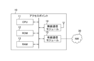
- FIG. 3 is a block diagram showing an example of the hardware configuration of the access point according to the embodiment.
- the access point 10 includes, for example, a CPU (Central Processing Unit) 11, a ROM (Read Only Memory) 12, a RAM (Random Access Memory) 13, a wireless communication module 14, and a wired communication module 15. Be prepared.
- a CPU Central Processing Unit
- ROM Read Only Memory
- RAM Random Access Memory
- the CPU 11 is a processing circuit that controls the overall operation of the access point 10.
- the ROM 12 is, for example, a nonvolatile semiconductor memory.
- the ROM 12 stores programs and data for controlling the access point 10.
- the RAM 13 is, for example, a volatile semiconductor memory.
- the RAM 13 is used as a work area for the CPU 11.
- the wireless communication module 14 is a circuit used for transmitting and receiving data using wireless signals.
- Wireless communication module 14 is connected to an antenna.
- the wired communication module 15 is a circuit used for transmitting and receiving data using wired signals. Wired communication module 15 is connected to network 30.
- FIG. 4 is a block diagram showing an example of the hardware configuration of the terminal according to the embodiment.
- the terminal 20 includes, for example, a CPU 21, a ROM 22, a RAM 23, a wireless communication module 24, a display 25, and a storage 26.
- the CPU 21 is a processing circuit that controls the overall operation of the terminal 20.
- the ROM 22 is, for example, a nonvolatile semiconductor memory.
- the ROM 22 stores programs and data for controlling the terminal 20.
- the RAM 23 is, for example, a volatile semiconductor memory. RAM23 is used as a work area for CPU21.
- the wireless communication module 24 is a circuit used for transmitting and receiving data using wireless signals. Wireless communication module 24 is connected to the antenna.
- the display 25 is, for example, an LCD (Liquid Crystal Display) or an EL (Electro-Luminescence) display.
- the display 25 displays a GUI (Graphical User Interface) and the like corresponding to application software.
- the storage 26 is a nonvolatile storage device.
- the storage 26 stores system software of the terminal 20 and the like.
- FIG. 5 is a block diagram showing an example of the functional configuration of the access point according to the embodiment.
- the access point 10 functions as a computer including an LLC processing section 110, a data processing section 120, a management section 130, a MAC frame processing section 140, a plurality of wireless signal processing sections 150, 160, and 170, and a transmission timing adjustment section 180.
- the LLC processing unit 110 is a functional block that executes processing corresponding to the LLC sublayer of the second layer and the third to seventh layers.
- the data processing unit 120, the management unit 130, and the MAC frame processing unit 140 are functional blocks that execute processing corresponding to the MAC sublayer of the second layer.
- the plurality of wireless signal processing units 150, 160, and 170 and the transmission timing adjustment unit 180 are functional blocks that execute processing corresponding to the MAC sublayer of the second layer and the first layer.
- the LLC processing unit 110 generates an LLC packet by adding, for example, a DSAP (Destination Service Access Point) header, an SSAP (Source Service Access Point) header, etc. to the data received from the network 30.
- the LLC processing unit 110 then inputs the generated LLC packet to the data processing unit 120. Further, the LLC processing unit 110 extracts data from the LLC packet input from the data processing unit 120. The LLC processing unit 110 then transmits the extracted data to the network 30.
- the data processing unit 120 adds a MAC header to the LLC packet input from the LLC processing unit 110 to generate a MAC frame.
- the data processing unit 120 then inputs the generated MAC frame to the MAC frame processing unit 140.
- the data processing unit 120 extracts LLC packets from the MAC frame input from the MAC frame processing unit 140.
- the data processing unit 120 then inputs the extracted LLC packet to the LLC processing unit 110.
- a MAC frame containing data is also referred to as a "data frame”.
- the management unit 130 manages the state of the link between the access point 10 and the terminal 20. Between the management unit 130 and the MAC frame processing unit 140, MAC frames containing management information regarding links, rTWT, etc. are input and output. In the following, the MAC frame including management information is also referred to as a "management frame.”
- the management section 130 includes link management information 131, a link management section 132, and a beacon management section 133.
- the link management information 131 is information regarding the link between the access point 10 and the wirelessly connected terminal 20.
- the link management information 131 includes, for example, the information shown in FIG. 2.
- the link management unit 132 controls the establishment of a link with the terminal 20. For example, the link management unit 132 executes association processing and subsequent authentication processing in response to a connection request from the terminal 20.
- the link management unit 132 controls the state of the link established with the terminal 20. For example, the link management unit 132 can determine the association between the TID and the STA function when establishing the multi-link ML.
- the beacon management unit 133 manages information transmitted by the access point 10 as a beacon signal. Specifically, the beacon management unit 133 generates a management frame that includes management information regarding the rTWT function. The beacon management unit 133 then inputs the generated management frame to the MAC frame processing unit 140. In the following, the management frame generated by the beacon management unit 133 is also referred to as a "beacon frame.”
- FIG. 6 is a diagram illustrating an example of the format of a beacon frame according to the embodiment.
- the beacon frame includes, for example, the rTWT-SP start time Ts and the rTWT-SP duration D as management information used in the rTWT function.
- the rTWT-SP start time Ts is information indicating the time when the service period rTWT-SP starts.
- the rTWT-SP duration D is information indicating the length of the service period rTWT-SP. That is, the service period rTWT-SP is set as a period from the rTWT-SP start time Ts to the time when the rTWT-SP continuation period D has elapsed.
- the rTWT-SP start time Ts and the rTWT-SP duration D are set for each link.
- the rTWT-SP start time Ts and rTWT-SP duration D set for each link are managed by the beacon management unit 133.
- the MAC frame processing unit 140 associates the MAC frame with a link. For example, when a MAC frame is input from the data processing unit 120, the MAC frame processing unit 140 identifies the link associated with the TID included in the MAC header by referring to the link management information 131. Then, the MAC frame processing section 140 inputs the MAC frame to the radio signal processing section corresponding to the identified link. Further, when a MAC frame is input from the plurality of wireless signal processing units 150, 160, and 170, the MAC frame processing unit 140 inputs the MAC frame to the data processing unit 120 or the management unit 130 depending on the type of the MAC frame. do. Specifically, the MAC frame processing unit 140 inputs the MAC frame to the data processing unit 120 when the MAC frame is a data frame. The MAC frame processing unit 140 inputs the MAC frame to the management unit 130 when the MAC frame is a management frame.
- the plurality of radio signal processing units 150, 160, and 170 correspond to STA1, STA2, and STA3 in the multilink ML shown in FIG. 2, respectively.
- Each of the plurality of wireless signal processing units 150, 160, and 170 has the same functional configuration.
- Each of the plurality of radio signal processing units 150, 160, and 170 adds a preamble or the like to the MAC frame input from the MAC frame processing unit 140 to generate a radio frame.
- Each of the plurality of radio signal processing units 150, 160, and 170 converts the generated radio frame into a radio signal. Then, each of the plurality of wireless signal processing units 150, 160, and 170 radiates (transmits) the converted wireless signal via the antenna.
- the conversion process from a radio frame to a radio signal includes, for example, convolutional encoding processing, interleaving processing, subcarrier modulation processing, inverse fast Fourier transform processing, OFDM (Orthogonal Frequency Division Multiplexing) modulation processing, and frequency conversion processing. Further, each of the plurality of radio signal processing units 150, 160, and 170 converts a radio signal received from the terminal 20 via the antenna into a radio frame.
- the conversion process from a radio signal to a radio frame includes, for example, frequency conversion process, OFDM demodulation process, fast Fourier transform process, subcarrier demodulation process, deinterleaving process, and Viterbi decoding process.
- Each of the plurality of radio signal processing units 150, 160, and 170 extracts a MAC frame from the converted radio frame. Then, each of the plurality of wireless signal processing units 150, 160, and 170 inputs the extracted MAC frame to the MAC frame processing unit 140.
- the transmission determination process is a process of determining whether or not to transmit a data frame.
- the transmission determination process includes carrier sense processing.
- Carrier sense processing is processing that determines the state of a channel used in a link. Details of the transmission determination process will be described later.
- the transmission timing adjustment unit 180 has a configuration that functions when the access point 10 operates as a transmitting station. In other words, when the access point 10 operates as a receiving station, the transmission timing adjustment section 180 may be omitted. Transmission timing adjustment section 180 manages the state regarding carrier sense processing in each of the plurality of radio signal processing sections 150, 160, and 170. Then, the transmission timing adjustment section 180 adjusts the transmission timing of the data frame by each of the plurality of wireless signal processing sections 150, 160, and 170 based on the state.
- FIG. 7 is a block diagram showing an example of the functional configuration of the terminal according to the embodiment.
- the terminal 20 includes an application execution section 200, an LLC processing section 210, a data processing section 220, a management section 230, a MAC frame processing section 240, a plurality of wireless signal processing sections 250, 260, and 270, and a transmission timing adjustment section 280.
- the application execution unit 200 is a functional block that executes processing corresponding to the seventh layer.
- the LLC processing unit 210 is a functional block that executes processing corresponding to the LLC sublayer of the second layer and the third to sixth layers.
- the data processing section 220, the management section 230, and the MAC frame processing section 240 are functional blocks that execute processing corresponding to the MAC sublayer of the second layer.
- the plurality of wireless signal processing units 250, 260, and 270 and the transmission timing adjustment unit 280 are functional blocks that execute processing corresponding to the MAC sublayer of the second layer and the first layer.
- the application execution unit 200 executes an application based on data input from the LLC processing unit 210. Further, the application execution unit 200 inputs data to the LLC processing unit 210. For example, the application execution unit 200 can display application information on the display 25. Further, the application execution unit 200 can operate based on the operation of the input interface.
- the LLC processing unit 210 adds a DSAP header, an SSAP header, etc. to the data from the application execution unit 200, and generates an LLC packet.
- the LLC processing unit 210 then inputs the generated LLC packet to the data processing unit 220. Additionally, the LLC processing unit 210 extracts data from the LLC packet input from the data processing unit 220. The LLC processing unit 210 then inputs the extracted data to the application execution unit 200.
- the data processing unit 220 adds a MAC header to the LLC packet input from the LLC processing unit 210 to generate a MAC frame.
- the data processing unit 220 then inputs the generated MAC frame to the MAC frame processing unit 240.
- the data processing unit 220 extracts LLC packets from the MAC frame input from the MAC frame processing unit 240.
- the data processing unit 220 then inputs the extracted LLC packet to the LLC processing unit 210.
- the management unit 230 manages the state of the link between the access point 10 and the terminal 20. Between the management unit 230 and the MAC frame processing unit 240, MAC frames containing management information regarding links, rTWT, etc. are input and output.
- the management section 230 includes link management information 231, a link management section 232, and a beacon management section 233.
- the link management information 231 is information regarding the link between the terminal 20 and the access point 10 that is wirelessly connected.
- the link management information 231 includes, for example, the information shown in FIG. 2.
- the link management unit 232 controls the establishment of a link with the access point 10. For example, the link management unit 232 executes an association process and a subsequent authentication process when transmitting a connection request to the access point 10.
- the link management unit 232 controls the state of the link established with the access point 10. For example, the link management unit 232 can determine the association between TID and STA function when establishing multi-link ML.
- the beacon management unit 233 manages information included in the beacon signal received from the access point 10. Specifically, the beacon management unit 233 extracts management information regarding the rTWT function from the beacon frame input from the MAC frame processing unit 240. Then, the beacon management unit 233 manages, for example, the rTWT-SP start time Ts and the rTWT-SP duration D among the extracted management information regarding the rTWT function for each link.
- the MAC frame processing unit 240 associates the MAC frame with a link. For example, when a MAC frame is input from the data processing unit 220, the MAC frame processing unit 240 identifies the link associated with the TID included in the MAC header by referring to the link management information 231. Then, the MAC frame processing section 240 inputs the MAC frame to the radio signal processing section corresponding to the identified link. Further, when a MAC frame is input from the plurality of wireless signal processing units 250, 260, and 270, the MAC frame processing unit 240 inputs the MAC frame to the data processing unit 220 or the management unit 230 depending on the type of the MAC frame. do.
- the MAC frame processing unit 240 inputs the MAC frame to the data processing unit 220 when the MAC frame is a data frame.
- the MAC frame processing unit 240 inputs the MAC frame to the management unit 230 when the MAC frame is a management frame.
- the plurality of radio signal processing units 250, 260, and 270 correspond to STA1, STA2, and STA3 in the multilink ML shown in FIG. 2, respectively.
- Each of the plurality of wireless signal processing units 250, 260, and 270 has the same functional configuration.
- Each of the plurality of radio signal processing units 250, 260, and 270 adds a preamble or the like to the MAC frame input from the MAC frame processing unit 240 to generate a radio frame.
- Each of the plurality of radio signal processing units 250, 260, and 270 converts the generated radio frame into a radio signal. Then, each of the plurality of wireless signal processing units 250, 260, and 270 radiates (transmits) the converted wireless signal via the antenna.
- the conversion process from a radio frame to a radio signal includes, for example, convolutional encoding processing, interleaving processing, subcarrier modulation processing, inverse fast Fourier transform processing, OFDM modulation processing, and frequency conversion processing. Further, each of the plurality of wireless signal processing units 250, 260, and 270 converts a wireless signal received from the access point 10 via the antenna into a wireless frame.
- the conversion process from a radio signal to a radio frame includes, for example, frequency conversion process, OFDM demodulation process, fast Fourier transform process, subcarrier demodulation process, deinterleaving process, and Viterbi decoding process.
- Each of the plurality of radio signal processing units 250, 260, and 270 extracts a MAC frame from the converted radio frame. Then, each of the plurality of wireless signal processing units 250, 260, and 270 inputs the extracted MAC frame to the MAC frame processing unit 240.
- the plurality of radio signal processing units 250, 260, and 270 execute transmission determination processing in cooperation with the transmission timing adjustment unit 280 prior to generating a radio frame.
- the transmission determination process at the terminal 20 is equivalent to the transmission determination process at the access point 10.
- the transmission timing adjustment unit 280 has a configuration that functions when the terminal 20 operates as a transmitting station. In other words, when the terminal 20 operates as a receiving station, the transmission timing adjustment section 280 may be omitted. Transmission timing adjustment section 280 manages the state regarding carrier sense processing in each of the plurality of radio signal processing sections 250, 260, and 270. Then, the transmission timing adjustment section 280 adjusts the transmission timing of the wireless signal by each of the plurality of wireless signal processing sections 250, 260, and 270 based on the state.
- each of the access point 10 and the terminal 20 functions as a transmitting station when executing the transmission determination process. Specifically, when the access point 10 executes the transmission determination process, each of the radio signal processing units 150, 160, and 170 functions as a transmission unit that operates in cooperation with the transmission timing adjustment unit 180. When the terminal 20 executes the transmission determination process, each of the radio signal processing sections 250, 260, and 270 functions as a transmission section that operates in cooperation with the transmission timing adjustment section 280. Below, as an example, a functional configuration related to transmission determination processing of the terminal 20 will be described.
- FIG. 8 is a block diagram illustrating an example of a functional configuration related to transmission determination processing of a terminal according to the embodiment.
- a beacon management section 233 a wireless signal processing section 250
- a transmission timing adjustment section 280 are illustrated. Note that the functional configuration of each of the wireless signal processing units 260 and 270 regarding the transmission determination process is the same as the functional configuration of the wireless signal processing unit 250 regarding the transmission determination process, and therefore a description thereof will be omitted.
- the radio signal processing section 250 includes a classification section 251, a plurality of queues 252A, 252B, 252C, and 252D, a plurality of carrier sense sections 253A, 253B, 253C, and 253D, and an internal collision management section 254.
- the classification unit 251 classifies the data frame into a plurality of access categories based on the TID included in the MAC header. Then, the classification unit 251 inputs the data frame to the corresponding queue 252 among the plurality of queues 252A, 252B, 252C, and 252D. In the example of FIG. 8, the classification unit 251 inputs data frames corresponding to access categories VO, VI, BE, and BK to queues 252A, 252B, 252C, and 252D, respectively.
- Each of the plurality of queues 252A, 252B, 252C, and 252D buffers input data frames.
- multiple queues 252A, 252B, 252C, and 252D buffer data frames corresponding to access categories VO, VI, BE, and BK, respectively.
- the plurality of carrier sense units 253A, 253B, 253C, and 253D correspond to the plurality of queues 252A, 252B, 252C, and 252D, respectively.
- Each of the plurality of carrier sense units 253A, 253B, 253C, and 253D executes carrier sense processing based on CSMA/CA (Carrier Sense Multiple Access with Collision Avoidance) according to preset access parameters. If it is determined that the channel is in an idle state for a predetermined period of time, each of the plurality of carrier sense units 253A, 253B, 253C, and 253D acquires the right to transmit a data frame and ends the carrier sense process. If it is determined that the channel is in a busy state, each of the plurality of carrier sense units 253A, 253B, 253C, and 253D stops acquiring the transmission right and ends the carrier sense process.
- CSMA/CA Carrier Sense Multiple Access with Collision Avoidance
- CWmin and CWmax indicate the minimum and maximum values of the contention window, respectively.
- the contention window is a parameter used to determine transmission waiting time for collision avoidance.
- AIFS is a fixed transmission waiting time set for each access category.
- TXOPLimit indicates the upper limit value of the channel occupation period TXOP. That is, the access category for which the shorter CWmin, CWmax, and AIFS are set, the easier it is to acquire the transmission right. Furthermore, the larger the TXOPLimit is set in the access category, the larger the amount of data that can be transmitted with one transmission right.
- each of the plurality of carrier sense units 253A, 253B, 253C, and 253D inputs the status STS of the carrier sense process, the scheduled transmission right acquisition time Tcs, the channel occupation period TXOP, etc. to the transmission timing adjustment unit 280. do.
- the status STS is information indicating the acquisition status of transmission rights through carrier sense processing.
- the status STS includes information such as "obtaining transmission right”, “transmission right acquired”, and “cancellation of transmission right acquisition", for example.
- a transmission control signal CNT is input from the transmission timing adjustment unit 280 to the carrier sense unit 253 that has acquired the transmission right.
- the transmission control signal CNT includes, for example, a transmission instruction and a transmission standby instruction.
- a transmission instruction is input, the carrier sense unit 253 that has acquired the transmission right takes out the data frame buffered in the corresponding queue 252.
- a transmission standby instruction is input, the carrier sense unit 253 that has acquired the transmission right waits without taking out a data frame from the corresponding queue 252.
- the longest channel occupation period TXOPmax is further input from the transmission timing adjustment unit 280.
- the longest channel occupation period TXOPmax is the maximum value of the channel occupation periods TXOP input from each of the radio signal processing sections 250, 260, and 270 to the transmission timing adjustment section 280.
- the carrier sense unit 253 that has acquired the transmission right adds padding to the data frame taken out from the corresponding queue 252 so that it is equal to the longest channel occupation period TXOPmax.
- the carrier sense unit 253 that has acquired the transmission right calculates the end time Te of the channel occupation period by the data frame to which padding has been added, and also acquires the rTWT-SP start time Ts of the corresponding link from the beacon management unit 233.
- the channel occupation period end time Te is, for example, the time at which the exchange of a data frame to which padding has been added and an Ack (Acknowledgement) corresponding to the data frame ends.
- the carrier sense unit 253 that has acquired the transmission right determines whether the channel occupation period end time Te is before the rTWT-SP start time Ts.
- the carrier sense unit 253 that has acquired the transmission right inputs the data frame with padding added to the internal collision management unit 254. If the channel occupation period end time Te is later than the rTWT-SP start time Ts, the carrier sense unit 253 that has acquired the transmission right postpones transmission of the data frame to which padding has been added.
- the internal collision management unit 254 prevents transmission collisions when two or more carrier sense units acquire transmission rights at the same time. Specifically, for example, when a plurality of data frames are input at the same time, the internal collision management unit 254 preferentially transmits a data frame of an access category with a high priority.
- the transmission timing adjustment unit 280 detects the completion of carrier sense processing in all carrier sense units 253 based on the status STS input from each of the plurality of radio signal processing units 250, 260, and 270. Until the carrier sense processing in all carrier sense units 253 is completed, the transmission timing adjustment unit 280 inputs a transmission standby instruction to the carrier sense unit 253 that has acquired the transmission right. After the end of the carrier sense processing in all the carrier sense units 253 is detected, the transmission timing adjustment unit 280 determines the maximum time in the carrier sense unit 253 that has acquired the transmission right based on the transmission right acquisition scheduled time Tcs and the channel occupation period TXOP. The channel occupation period TXOPmax is calculated. Then, the transmission timing adjustment unit 280 inputs the calculated longest channel occupation period TXOPmax together with the transmission control signal CNT including the transmission instruction to the carrier sense unit 253 that has acquired the transmission right.
- the terminal 20 is a transmitting station.
- the access point 10 is a transmitting station.
- the terminal 20 is a receiving station.
- the access point 10 is a transmitting station.
- a case where the terminal 20 serves as a transmitting station will be described as an example.
- FIG. 9 is a flowchart illustrating an example of transmission determination processing in the radio signal processing unit of the transmitting station according to the embodiment.
- the plurality of wireless signal processing units 250, 260, and 270 perform equivalent transmission determination processing.
- the transmission determination process in the radio signal processing section 250 will be described below with reference to FIG. 9.
- each of the plurality of carrier sense units 253A, 253B, 253C, and 253D of the radio signal processing unit 250 sends a status STS of “transmission right acquisition” to the transmission timing adjustment unit 280. (S10).
- Each of the plurality of carrier sense units 253A, 253B, 253C, and 253D notifies the transmission timing adjustment unit 280 of the transmission right acquisition scheduled time Tcs and the channel occupation period TXOP (S11).
- Each of the plurality of carrier sense units 253A, 253B, 253C, and 253D determines whether or not the transmission right has been acquired (S12).
- the carrier sense unit 253 that has acquired the transmission right notifies the transmission timing adjustment unit 280 of the status STS of “transmission right acquired” (S13).
- the carrier sense unit 253 that could not acquire the transmission right notifies the transmission timing adjustment unit 280 of the status STS of “transmission right acquisition canceled” (S14).
- the carrier sense unit 253 that has acquired the transmission right waits until it is notified of the transmission instruction and the longest channel occupation period TXOPmax from the transmission timing adjustment unit 280 (S15).
- the carrier sense section 253 takes out the data frame from the corresponding queue 252. Then, the carrier sense unit 253 that has acquired the transmission right adds padding to the data frame so that the channel occupation period TXOP is aligned with the longest channel occupation period TXOPmax (S16).
- the carrier sense unit 253 that has acquired the transmission right calculates the channel occupation period end time Te based on the data frame to which padding was added in the process of S16 (S17).
- the carrier sense unit 253 that has acquired the transmission right determines whether the channel occupation period end time Te calculated in the process of S17 is before the rTWT-SP start time Ts managed by the beacon management unit 233. (S18).
- the carrier sense unit 253 that has acquired the transmission right starts transmitting the data frame to which padding has been added (S19). ).
- the carrier sense unit 253 that has acquired the transmission right inputs the data frame to which padding has been added to the internal collision management unit 254.
- the internal collision management unit 254 selects a data frame with a high priority.
- the wireless signal processing unit 250 converts the selected data frame into a wireless signal and transmits it to the access point 10.
- the carrier sense unit 253 postpones the transmission of the data frame (S20). Specifically, after the process of S14, the carrier sense unit 253 that has not been able to acquire the transmission right postpones the transmission of the data frame. If the channel occupation period end time Te is later than the rTWT-SP start time Ts (S18; no), the carrier sense unit 253 that has acquired the transmission right postpones transmission of the data frame to which padding has been added.
- the transmission determination process in the wireless signal processing unit 250 ends (end).
- FIG. 10 is a flowchart illustrating an example of transmission determination processing in the transmission timing adjustment unit of the transmitting station according to the embodiment.
- the transmission timing adjustment unit 280 waits until the status STS of "transmission right acquisition in progress" is updated to "transmission right acquisition completed” or "transmission right acquisition canceled” (S30). .
- the transmission timing adjustment unit 280 determines whether the status STS updated during the process of S30 has been updated to "transmission right acquired” (S31).
- the transmission timing adjustment unit 280 notifies the carrier sense unit 253 whose status STS is updated to "transmission right acquired” of a transmission standby instruction. (S32).
- the transmission timing adjustment unit 280 updates the carrier sense unit 253 whose status STS is "transmission right acquired” It is determined whether there is one (S33).
- the transmission timing adjustment unit 280 determines whether the status STS “acquiring transmission right” is “acquired transmission right” or “transmission right acquired”. The process waits until it is updated to "Cancel acquisition” (S30). After the process of S30, subsequent processes of S31, S32, and S33 are executed. In this way, the processes of S30 to S33 are repeated until there are no carrier sense units 253 whose status STS is "acquiring transmission right”.
- the transmission timing adjustment unit 280 calculates the longest channel occupation period TXOPmax in the carrier sense unit 253 whose status STS is “acquiring transmission right”. (S34).
- the transmission timing adjustment unit 280 notifies the carrier sense unit 253 whose status STS is “transmission right acquired” of the transmission instruction and the longest channel occupation period TXOPmax calculated in the process of S34 (S35).
- the transmission determination process in the transmission timing adjustment section 280 ends (end).
- FIG. 11 is a diagram illustrating an example of transmission determination processing at the transmitting station according to the embodiment.
- FIG. 11 shows an example of a transmission determination process when multilink ML is established by three pairs of STA functions (STA1, STA2, and STA3) in a certain period.
- STA1, STA2, and STA3 three situations are shown in chronological order in the order of (A), (B), and (C).
- FIG. 11(A) shows the schedule of each STA function when carrier sense processing is started.
- STA1, STA2, and STA3 are attempting to obtain transmission rights for traffic exchange during channel occupancy periods TXOP1, TXOP2, and TXOP3, respectively.
- the end time Te1 of the channel occupation period TXOP1 is after the end time Te2 of the channel occupation period TXOP2.
- the end time Te2 of the channel occupation period TXOP2 is after the end time Te3 of the channel occupation period TXOP3.
- a service period rTWT-SP is set from the rTWT-SP start time Ts. At this point, the service period rTWT-SP does not overlap with the channel occupation period TXOP3 of STA3.
- (B) in FIG. 11 shows the schedule of each STA function when the carrier sense process is completed.
- STA1 fails to acquire the transmission right.
- STA1 postpones the transmission of the data frame.
- STA2 and STA3 succeed in acquiring the transmission right. Therefore, the transmission timing adjustment unit 280 notifies STA2 and STA3 of the channel occupancy period TXOP2 as the longest channel occupancy period TXOPmax along with the transmission instruction.
- FIG. 11C shows the schedule of each STA function when the transmission determination process is completed.
- the transmission of data frames by STA1 and STA3 is postponed. Therefore, data frames by STA2 are transmitted during the occupied period. Then, by postponing the transmission of the data frame by STA3, overlap between the service period rTWT-SP set for STA3 and the exclusive period for transmitting the data frame with padding added is avoided.
- the STA function that has acquired the transmission right may transmit data in conjunction with the data transmission by other STA functions that have acquired the transmission right. , is configured to postpone transmitting the data to which the padding has been added. Therefore, it is possible to suppress the exchange of low-latency traffic during the service period rTWT-SP from being inhibited. Therefore, it is possible to provide a wireless communication environment in which low-latency traffic can be exchanged preferentially.
- the carrier sense unit 253 that has acquired the transmission right adds padding so that its own channel occupation period TXOP is aligned with the longest channel occupation period TXOPmax.
- the channel occupation period TXOP includes a period for receiving an Ack from the receiving station. Thereby, it is possible to align the channel occupation period end times Te among the plurality of channels forming the multilink ML. Therefore, it is possible to avoid the operation of transmitting data on one channel and receiving data on the other channel.
- the transmission timing adjustment unit 280 notifies the carrier sense unit 253 that has acquired the transmission right of a transmission standby instruction. Thereby, data can be simultaneously transmitted between a plurality of channels making up the multilink ML. In addition, padding based on the longest channel occupancy period TXOPmax can facilitate estimation of the additional period.
- the radio signal processing unit 250 transmits data with lower latency during the service period rTWT-SP than data transmitted during periods outside the service period rTWT-SP. This allows low-latency traffic to be exchanged preferentially.
- the access point 10 notifies the service period rTWT-SP using a beacon signal. Thereby, the terminal 20 can receive the latest rTWT-SP start time Ts and rTWT-SP duration D in a timely manner.
- the transmission timing adjustment unit 280 notifies the carrier sense unit 253 that has “acquired the transmission right” of a transmission standby instruction until there are no more carrier sense units 253 that are “acquiring the transmission right”.
- the transmission timing adjustment unit 280 may not notify the transmission standby instruction. In this case, the carrier sense unit 253 that has “acquired the transmission right” waits until it is notified of a transmission instruction from the transmission timing adjustment unit 280.
- the transmission determination process according to the embodiment and modification described above can also be stored as a program that can be executed by a processor that is a computer.
- it can be stored and distributed in a storage medium of an external storage device such as a magnetic disk, an optical disk, or a semiconductor memory. Then, the processor reads the program stored in the storage medium of the external storage device, and its operation is controlled by the read program, thereby being able to execute the transmission determination process.
- the present invention is not limited to the above-described embodiments, and can be variously modified at the implementation stage without departing from the gist thereof.
- each embodiment may be implemented in combination as appropriate, and in that case, the combined effect can be obtained.
- the embodiments described above include various inventions, and various inventions can be extracted by combinations selected from the plurality of constituent features disclosed. For example, if a problem can be solved and an effect can be obtained even if some constituent features are deleted from all the constituent features shown in the embodiment, the structure from which these constituent features are deleted can be extracted as an invention.
Landscapes
- Engineering & Computer Science (AREA)
- Computer Security & Cryptography (AREA)
- Computer Networks & Wireless Communication (AREA)
- Signal Processing (AREA)
- Mobile Radio Communication Systems (AREA)
Abstract
送信局は、第1送信部と、第2送信部と、管理部と、を備える。管理部は、受信局との間で、第1送信部に第1チャネルを割り当てて第2送信部に第2チャネルを割り当てるマルチリンクを確立し、第1チャネルにサービス期間を割り当てる。第1送信部は、第1データ及びパディングを送信するための第1占有期間がサービス期間と重複する場合、第2送信部による第2データの送信に合わせた第1データ及びパディングの送信を延期するように構成される。
Description
実施形態は、送信局、送信方法、及び送信プログラムに関する。
アクセスポイントと端末との間を無線で接続するシステムとして、無線LAN(Local Area Network)が知られている。無線LANにより、アクセスポイントの通信領域内に位置する端末は、当該アクセスポイントを介して、ネットワークにアクセスすることができる。アクセスポイント及び端末は、低レイテンシのトラヒックを優先的に交換するためのサービス期間を設ける場合がある。
IEEE P802.11beTM/D1.5, "35.9 Restricted TWT (r-TWT)", March 18, 2022
低レイテンシのトラヒックを優先的に交換するためには、他のトラヒックの交換期間が当該サービス期間と重複しないように、送信制御が行われることが望ましい。
本発明は、上記事情に着目してなされたもので、その目的とするところは、低レイテンシのトラヒックを優先的に交換することができる無線通信環境を提供することにある。
一態様の送信局は、第1送信部と、第2送信部と、管理部と、を備える。上記管理部は、受信局との間で、上記第1送信部に第1チャネルを割り当てて上記第2送信部に第2チャネルを割り当てるマルチリンクを確立し、上記第1チャネルにサービス期間を割り当てる。上記第1送信部は、第1データ及びパディングを送信するための第1占有期間が上記サービス期間と重複する場合、上記第2送信部による第2データの送信に合わせた上記第1データ及び上記パディングの送信を延期するように構成される。
実施形態によれば、低レイテンシのトラヒックを優先的に交換することができる無線通信環境を提供することができる。
以下、図面を参照して実施形態について説明する。なお、以下の説明において、同一の機能及び構成を有する構成要素については、共通する参照符号を付す。
(実施形態)
1. 構成
実施形態に係る通信システムの構成について説明する。
1. 構成
実施形態に係る通信システムの構成について説明する。
1.1 通信システム
図1は、実施形態に係る通信システムの構成の一例を示すブロック図である。
図1は、実施形態に係る通信システムの構成の一例を示すブロック図である。
図1に示すように、通信システム1は、アクセスポイント10、端末20、及びネットワーク30を備える。
アクセスポイント10は、例えば、無線LANの基地局である。アクセスポイント10は、有線又は無線を介してネットワーク30上のサーバ(図示せず)と通信するように構成される。アクセスポイント10は、無線を介して端末20と通信するように構成される。アクセスポイント10と端末20との間の通信は、例えばIEEE802.11規格に準拠する。
端末20は、例えば、スマートフォンやPC(Personal Computer)等の無線端末である。端末20は、アクセスポイント10を介して、ネットワーク30上のサーバと通信するように構成される。
アクセスポイント10及び端末20は、例えば、OSI(Open Systems Interconnection)参照モデルに基づく無線通信機能を有する。OSI参照モデルでは、無線通信機能が7階層(第1層:物理層、第2層:データリンク層、第3層:ネットワーク層、第4層:トランスポート層、第5層:セッション層、第6層:プレゼンテーション層、第7層:アプリケーション層)に分割される。データリンク層は、LLC(Logical Link Control)副層、及びMAC(Media Access Control)副層を含む。
アクセスポイント10と端末20との間の無線接続方式には、マルチリンクMLが適用され得る。マルチリンクMLは、複数のリンクを同時に用いてデータを送受信(トラヒックを交換)することができる無線接続方式である。マルチリンクMLが適用されるアクセスポイント10及び端末20は、リンク管理情報によってマルチリンクMLの状態を管理する。
図2は、実施形態に係る通信システムのリンク管理情報の一例を示す図である。リンク管理情報は、例えば、“リンクID”、“リンク”、“周波数帯”、“チャネルID”、“マルチリンク”、及び“トラヒック”のそれぞれの情報を含む。
“リンクID”は、STA機能に関連づけられた識別子である。STA機能は、アクセスポイント10と端末20との間でリンクを確立するために、アクセスポイント10及び端末20の各々が備える機能構成である。すなわち、1対のSTA機能が、1個のリンクの確立に使用される。図2の例では、アクセスポイント10と端末20との間の無線通信に、3対のSTA機能(STA1、STA2、及びSTA3)が割り当てられる場合が示される。STA機能は、後述する無線信号処理部に対応する。
“リンク”は、STA機能によってアクセスポイント10と端末20との間でリンクが確立されているか否かを示す情報である。図2の例では、STA1、STA2、及びSTA3の全てがアクセスポイント10と端末20との間でリンクを確立している場合が示される。
“周波数帯”は、リンクに使用される周波数帯を示す情報である。周波数帯は、例えば、6GHz帯、5GHz帯、及び2.4GHz帯等が適用され得る。各周波数帯は、複数のチャネルを含む。図2の例では、STA1、STA2、及びSTA3の全てに、5GHz帯が割り当てられる場合が示される。
“チャネルID”は、リンクに使用されるチャネルの識別子である。図2の例では、STA1、STA2、及びSTA3に、5GHz帯のチャネルCH1、CH2、及びCH3がそれぞれ割り当てられる場合が示される。チャネルCH1、CH2、及びCH3には、例えば、互いに電力漏洩が発生する程度に近い周波数帯が割り当てられる場合がある。
“マルチリンク”は、アクセスポイント10及び端末20がマルチリンクMLを確立しているか否かを示す情報である。図2の例では、STA1、STA2、及びSTA3の組が、マルチリンクMLを確立している場合が示される。
“トラヒック”は、STA機能に割り当てられるTID(Traffic Indicator)を示す情報である。TIDは、各トラヒックを示す識別子であり、それぞれアクセスカテゴリと対応づけられてもよい。トラヒックのアクセスカテゴリは、例えば、“VO(Voice)”、“VI(Video)”、“BE(Best Effort)”、“BK(Background)”、及び“LL(Low Latency)”を含む。アクセスカテゴリLLは、低遅延(低レイテンシ)が要求されるトラヒックである。図2のTID#1~#4の各々は、例えば、アクセスカテゴリVO、VI、BE、BK、及びLLのいずれかに対応する。図2の例では、TID#1がSTA1、STA2、及びSTA3に割り当てられる場合が示される。また、TID#2、#3、及び#4がそれぞれSTA1、STA2、及びSTA3に更に割り当てられる場合が示される。
このように、マルチリンクMLでは、1個のTIDに対して1又は複数のSTA機能が割り当てられ得る。トラヒックとSTA機能との関連づけは、例えば、マルチリンクMLを構成する複数のリンクの間でトラヒック量が均等になるように設定される。なお、トラヒックとSTA機能との関連づけは、上述の例に限られず、例えば、低レイテンシが要求されるトラヒック、及び低レイテンシが要求されないトラヒック等のように、互いに類似する種類のトラヒックがマルチリンクMLを構成する特定のリンクに集められてもよい。
アクセスポイント10及び端末20は、上述したマルチリンクMLにおいて低レイテンシが要求されるトラヒックの交換機会を確保するためのrTWT(restricted Target Wake Time)機能を有する。アクセスポイント10及び端末20は、rTWT機能を利用することによって、低レイテンシが要求されているトラヒックの交換を、低レイテンシが要求されないトラヒックの交換より優先可能なサービス期間を設定することができる。このようなサービス期間は、rTWT-SP(Service Period)とも呼ばれる。
1.2 ハードウェア構成
次に、実施形態に係る通信システムにおけるアクセスポイント及び端末のハードウェア構成について説明する。
次に、実施形態に係る通信システムにおけるアクセスポイント及び端末のハードウェア構成について説明する。
1.2.1 アクセスポイントのハードウェア構成
図3は、実施形態に係るアクセスポイントのハードウェア構成の一例を示すブロック図である。
図3は、実施形態に係るアクセスポイントのハードウェア構成の一例を示すブロック図である。
図3に示すように、アクセスポイント10は、例えば、CPU(Central Processing Unit)11、ROM(Read Only Memory)12、RAM(Random Access Memory)13、無線通信モジュール14、及び有線通信モジュール15、を備える。
CPU11は、アクセスポイント10の全体の動作を制御する処理回路である。ROM12は、例えば、不揮発性の半導体メモリである。ROM12は、アクセスポイント10を制御するためのプログラム、及びデータを記憶する。RAM13は、例えば、揮発性の半導体メモリである。RAM13は、CPU11の作業領域として使用される。無線通信モジュール14は、無線信号によるデータの送受信に使用される回路である。無線通信モジュール14は、アンテナに接続される。有線通信モジュール15は、有線信号によるデータの送受信に使用される回路である。有線通信モジュール15は、ネットワーク30に接続される。
1.2.2 端末のハードウェア構成
図4は、実施形態に係る端末のハードウェア構成の一例を示すブロック図である。
図4は、実施形態に係る端末のハードウェア構成の一例を示すブロック図である。
図4に示すように、端末20は、例えば、CPU21、ROM22、RAM23、無線通信モジュール24、ディスプレイ25、及びストレージ26を備える。
CPU21は、端末20の全体の動作を制御する処理回路である。ROM22は、例えば、不揮発性の半導体メモリである。ROM22は、端末20を制御するためのプログラム、及びデータを記憶する。RAM23は、例えば、揮発性の半導体メモリである。RAM23は、CPU21の作業領域として使用される。無線通信モジュール24は、無線信号によるデータの送受信に使用される回路である。無線通信モジュール24は、アンテナに接続される。ディスプレイ25は、例えばLCD(Liquid Crystal Display)又はEL(Electro-Luminescence)ディスプレイである。ディスプレイ25は、アプリケーションソフトに対応するGUI(Graphical User Interface)等を表示する。ストレージ26は、不揮発性の記憶装置である。ストレージ26は、端末20のシステムソフトウェア等を記憶する。
1.3 機能構成
次に、実施形態に係る通信システムにおけるアクセスポイント及び端末の機能構成について説明する。
次に、実施形態に係る通信システムにおけるアクセスポイント及び端末の機能構成について説明する。
1.3.1 アクセスポイントの機能構成
図5は、実施形態に係るアクセスポイントの機能構成の一例を示すブロック図である。
図5は、実施形態に係るアクセスポイントの機能構成の一例を示すブロック図である。
アクセスポイント10は、LLC処理部110、データ処理部120、管理部130、MACフレーム処理部140、複数の無線信号処理部150、160、及び170、並びに送信タイミング調整部180を備えるコンピュータとして機能する。LLC処理部110は、第2層のLLC副層及び第3層から第7層に対応する処理を実行する機能ブロックである。データ処理部120、管理部130、及びMACフレーム処理部140は、第2層のMAC副層に対応する処理を実行する機能ブロックである。複数の無線信号処理部150、160、及び170、並びに送信タイミング調整部180は、第2層のMAC副層及び第1層に対応する処理を実行する機能ブロックである。
LLC処理部110は、例えば、ネットワーク30から受信したデータにDSAP(Destination Service Access Point)ヘッダやSSAP(Source Service Access Point)ヘッダ等を付加して、LLCパケットを生成する。そして、LLC処理部110は、生成されたLLCパケットを、データ処理部120に入力する。また、LLC処理部110は、データ処理部120から入力されたLLCパケットからデータを抽出する。そして、LLC処理部110は、抽出されたデータを、ネットワーク30に送信する。
データ処理部120は、LLC処理部110から入力されたLLCパケットにMACヘッダを付加して、MACフレームを生成する。そして、データ処理部120は、生成されたMACフレームをMACフレーム処理部140に入力する。また、データ処理部120は、MACフレーム処理部140から入力されたMACフレームからLLCパケットを抽出する。そして、データ処理部120は、抽出されたLLCパケットをLLC処理部110に入力する。以下では、データを含むMACフレームは、“データフレーム”とも呼ばれる。
管理部130は、アクセスポイント10と端末20との間のリンクの状態を管理する。管理部130とMACフレーム処理部140との間では、リンクやrTWT等に関する管理情報を含むMACフレームが入出力される。以下では、管理情報を含むMACフレームは、“マネジメントフレーム”とも呼ばれる。管理部130は、リンク管理情報131、リンク管理部132、及びビーコン管理部133を含む。
リンク管理情報131は、アクセスポイント10と無線接続された端末20とのリンクに関する情報である。リンク管理情報131は、例えば、図2に示される情報を含む。
リンク管理部132は、端末20との間のリンクの確立を制御する。例えば、リンク管理部132は、端末20からの接続要求に応じて、アソシエーション処理及び後続する認証処理を実行する。リンク管理部132は、端末20との間で確立されたリンクの状態を制御する。例えば、リンク管理部132は、マルチリンクMLの確立に際して、TIDとSTA機能との対応付けを決定し得る。
ビーコン管理部133は、アクセスポイント10がビーコン信号として発信する情報を管理する。具体的には、ビーコン管理部133は、rTWT機能に関する管理情報を含むマネジメントフレームを生成する。そして、ビーコン管理部133は、生成されたマネジメントフレームをMACフレーム処理部140に入力する。以下では、ビーコン管理部133によって生成されるマネジメントフレームは、“ビーコンフレーム”とも呼ばれる。
図6は、実施形態に係るビーコンフレームのフォーマットの一例を示す図である。図6に示されるように、ビーコンフレームは、例えば、rTWT機能で使用される管理情報として、rTWT-SP開始時刻Ts及びrTWT-SP継続期間Dを含む。
rTWT-SP開始時刻Tsは、サービス期間rTWT-SPが開始される時刻を示す情報である。rTWT-SP継続期間Dは、サービス期間rTWT-SPの長さを示す情報である。つまり、サービス期間rTWT-SPは、rTWT-SP開始時刻Tsから、rTWT-SP継続期間Dが経過した時刻までの期間として設定される。rTWT-SP開始時刻Ts及びrTWT-SP継続期間Dは、リンク毎に設定される。そして、リンク毎に設定されたrTWT-SP開始時刻Ts及びrTWT-SP継続期間Dは、ビーコン管理部133によって管理される。
再び図5に戻って、アクセスポイント10の機能構成について説明する。
MACフレーム処理部140は、データ処理部120又は管理部130からMACフレームが入力されると、当該MACフレームとリンクとを関連づける。例えば、データ処理部120からMACフレームが入力された場合、MACフレーム処理部140は、リンク管理情報131を参照することによって、MACヘッダに含まれるTIDに関連づけられたリンクを特定する。そして、MACフレーム処理部140は、特定されたリンクに対応する無線信号処理部にMACフレームを入力する。また、MACフレーム処理部140は、複数の無線信号処理部150、160、及び170からMACフレームが入力されると、MACフレームの種別に応じてMACフレームをデータ処理部120又は管理部130に入力する。具体的には、MACフレーム処理部140は、MACフレームがデータフレームである場合には、MACフレームをデータ処理部120に入力する。MACフレーム処理部140は、MACフレームがマネジメントフレームである場合には、MACフレームを管理部130に入力する。
複数の無線信号処理部150、160、及び170はそれぞれ、図2で示されるマルチリンクMLにおけるSTA1、STA2、及びSTA3に対応する。複数の無線信号処理部150、160、及び170はそれぞれ、同等の機能構成を有する。複数の無線信号処理部150、160、及び170の各々は、MACフレーム処理部140から入力されたMACフレームにプリアンブル等を付加して、無線フレームを生成する。複数の無線信号処理部150、160、及び170の各々は、生成された無線フレームを無線信号に変換する。そして、複数の無線信号処理部150、160、及び170の各々は、変換された無線信号を、アンテナを介して放射(送信)する。無線フレームから無線信号への変換処理は、例えば、畳込符号化処理、インタリーブ処理、サブキャリア変調処理、逆高速フーリエ変換処理、OFDM(Orthogonal Frequency Division Multiplexing)変調処理、及び周波数変換処理を含む。また、複数の無線信号処理部150、160、及び170の各々は、アンテナを介して受信した端末20からの無線信号を無線フレームに変換する。無線信号から無線フレームへの変換処理は、例えば、周波数変換処理、OFDM復調処理、高速フーリエ変換処理、サブキャリア復調処理、デインタリーブ処理、及びビタビ復号処理を含む。複数の無線信号処理部150、160、及び170の各々は、変換された無線フレームからMACフレームを抽出する。そして、複数の無線信号処理部150、160、及び170の各々は、抽出されたMACフレームをMACフレーム処理部140に入力する。
なお、複数の無線信号処理部150、160、及び170は、無線フレームの生成に先立ち、送信タイミング調整部180と協調して送信判定処理を実行する。送信判定処理は、データフレームを送信するか否かを判定する処理である。送信判定処理は、キャリアセンス処理を含む。キャリアセンス処理は、リンクで使用されるチャネルの状態を判定する処理である。送信判定処理の詳細については後述する。
送信タイミング調整部180は、アクセスポイント10が送信局として動作する際に機能する構成である。言い換えると、アクセスポイント10が受信局として動作する際には、送信タイミング調整部180は、省略され得る。送信タイミング調整部180は、複数の無線信号処理部150、160、及び170の各々におけるキャリアセンス処理に関する状態を管理する。そして、送信タイミング調整部180は、当該状態に基づき、複数の無線信号処理部150、160、及び170の各々によるデータフレームの送信タイミングを調整する。
1.3.2 端末の機能構成
図7は、実施形態に係る端末の機能構成の一例を示すブロック図である。
図7は、実施形態に係る端末の機能構成の一例を示すブロック図である。
端末20は、アプリケーション実行部200、LLC処理部210、データ処理部220、管理部230、MACフレーム処理部240、複数の無線信号処理部250、260、及び270、並びに送信タイミング調整部280を備えるコンピュータとして機能する。アプリケーション実行部200は、第7層に対応する処理を実行する機能ブロックである。LLC処理部210は、第2層のLLC副層及び第3層から第6層に対応する処理を実行する機能ブロックである。データ処理部220、管理部230、及びMACフレーム処理部240は、第2層のMAC副層に対応する処理を実行する機能ブロックである。複数の無線信号処理部250、260、及び270、並びに送信タイミング調整部280は、第2層のMAC副層及び第1層に対応する処理を実行する機能ブロックである。
アプリケーション実行部200は、LLC処理部210から入力されたデータに基づき、アプリケーションを実行する。また、アプリケーション実行部200は、LLC処理部210にデータを入力する。例えば、アプリケーション実行部200は、アプリケーションの情報をディスプレイ25に表示することができる。また、アプリケーション実行部200は、入力インタフェースの操作に基づいて動作し得る。
LLC処理部210は、アプリケーション実行部200からデータにDSAPヘッダやSSAPヘッダ等を付加して、LLCパケットを生成する。そして、LLC処理部210は、生成されたLLCパケットを、データ処理部220に入力する。また、LLC処理部210は、データ処理部220から入力されたLLCパケットからデータを抽出する。そして、LLC処理部210は、抽出されたデータを、アプリケーション実行部200に入力する。
データ処理部220は、LLC処理部210から入力されたLLCパケットにMACヘッダを付加して、MACフレームを生成する。そして、データ処理部220は、生成されたMACフレームをMACフレーム処理部240に入力する。また、データ処理部220は、MACフレーム処理部240から入力されたMACフレームからLLCパケットを抽出する。そして、データ処理部220は、抽出されたLLCパケットをLLC処理部210に入力する。
管理部230は、アクセスポイント10と端末20との間のリンクの状態を管理する。管理部230とMACフレーム処理部240との間では、リンクやrTWT等に関する管理情報を含むMACフレームが入出力される。管理部230は、リンク管理情報231、リンク管理部232、及びビーコン管理部233を含む。
リンク管理情報231は、端末20と無線接続されたアクセスポイント10とのリンクに関する情報である。リンク管理情報231は、例えば、図2に示される情報を含む。
リンク管理部232は、アクセスポイント10との間のリンクの確立を制御する。例えば、リンク管理部232は、アクセスポイント10に接続要求を送信する際に、アソシエーション処理及び後続する認証処理を実行する。リンク管理部232は、アクセスポイント10との間で確立されたリンクの状態を制御する。例えば、リンク管理部232は、マルチリンクMLの確立に際して、TIDとSTA機能との対応付けを決定し得る。
ビーコン管理部233は、アクセスポイント10から受信したビーコン信号に含まれる情報を管理する。具体的には、ビーコン管理部233は、MACフレーム処理部240から入力されたビーコンフレームからrTWT機能に関する管理情報を抽出する。そして、ビーコン管理部233は、例えば、抽出されたrTWT機能に関する管理情報のうちrTWT-SP開始時刻Ts及びrTWT-SP継続期間Dをリンク毎に管理する。
MACフレーム処理部240は、データ処理部220又は管理部230からMACフレームが入力されると、当該MACフレームとリンクとを関連づける。例えば、データ処理部220からMACフレームが入力された場合、MACフレーム処理部240は、リンク管理情報231を参照することによって、MACヘッダに含まれるTIDに関連づけられたリンクを特定する。そして、MACフレーム処理部240は、特定されたリンクに対応する無線信号処理部にMACフレームを入力する。また、MACフレーム処理部240は、複数の無線信号処理部250、260、及び270からMACフレームが入力されると、MACフレームの種別に応じてMACフレームをデータ処理部220又は管理部230に入力する。具体的には、MACフレーム処理部240は、MACフレームがデータフレームである場合には、MACフレームをデータ処理部220に入力する。MACフレーム処理部240は、MACフレームがマネジメントフレームである場合には、MACフレームを管理部230に入力する。
複数の無線信号処理部250、260、及び270はそれぞれ、図2で示されたマルチリンクMLにおけるSTA1、STA2、及びSTA3に対応する。複数の無線信号処理部250、260、及び270はそれぞれ、同等の機能構成を有する。複数の無線信号処理部250、260、及び270の各々は、MACフレーム処理部240から入力されたMACフレームにプリアンブル等を付加して、無線フレームを生成する。複数の無線信号処理部250、260、及び270の各々は、生成された無線フレームを無線信号に変換する。そして、複数の無線信号処理部250、260、及び270の各々は、変換された無線信号を、アンテナを介して放射(送信)する。無線フレームから無線信号への変換処理は、例えば、畳込符号化処理、インタリーブ処理、サブキャリア変調処理、逆高速フーリエ変換処理、OFDM変調処理、及び周波数変換処理を含む。また、複数の無線信号処理部250、260、及び270の各々は、アンテナを介して受信したアクセスポイント10からの無線信号を無線フレームに変換する。無線信号から無線フレームへの変換処理は、例えば、周波数変換処理、OFDM復調処理、高速フーリエ変換処理、サブキャリア復調処理、デインタリーブ処理、及びビタビ復号処理を含む。複数の無線信号処理部250、260、及び270の各々は、変換された無線フレームからMACフレームを抽出する。そして、複数の無線信号処理部250、260、及び270の各々は、抽出されたMACフレームをMACフレーム処理部240に入力する。
なお、複数の無線信号処理部250、260、及び270は、無線フレームの生成に先立ち、送信タイミング調整部280と協調して送信判定処理を実行する。端末20における送信判定処理は、アクセスポイント10における送信判定処理と同等の処理である。
送信タイミング調整部280は、端末20が送信局として動作する際に機能する構成である。言い換えると、端末20が受信局として動作する際には、送信タイミング調整部280は、省略され得る。送信タイミング調整部280は、複数の無線信号処理部250、260、及び270の各々におけるキャリアセンス処理に関する状態を管理する。そして、送信タイミング調整部280は、当該状態に基づき、複数の無線信号処理部250、260、及び270の各々による無線信号の送信タイミングを調整する。
1.3.3 送信判定処理に関する機能構成
次に、実施形態に係るアクセスポイント10及び端末20の各々の送信判定処理に関する機能構成について説明する。アクセスポイント10及び端末20の各々は、送信判定処理を実行する際、送信局として機能する。具体的には、アクセスポイント10が送信判定処理を実行する際、無線信号処理部150、160、及び170の各々は、送信タイミング調整部180と協調して動作する送信部として機能する。端末20が送信判定処理を実行する際、無線信号処理部250、260、及び270の各々は、送信タイミング調整部280と協調して動作する送信部として機能する。以下では、一例として、端末20の送信判定処理に関する機能構成について説明する。
次に、実施形態に係るアクセスポイント10及び端末20の各々の送信判定処理に関する機能構成について説明する。アクセスポイント10及び端末20の各々は、送信判定処理を実行する際、送信局として機能する。具体的には、アクセスポイント10が送信判定処理を実行する際、無線信号処理部150、160、及び170の各々は、送信タイミング調整部180と協調して動作する送信部として機能する。端末20が送信判定処理を実行する際、無線信号処理部250、260、及び270の各々は、送信タイミング調整部280と協調して動作する送信部として機能する。以下では、一例として、端末20の送信判定処理に関する機能構成について説明する。
図8は、実施形態に係る端末の送信判定処理に関する機能構成の一例を示すブロック図である。図8の例では、ビーコン管理部233、無線信号処理部250、及び送信タイミング調整部280が図示される。なお、無線信号処理部260及び270の各々の送信判定処理に関する機能構成は、無線信号処理部250の送信判定処理に関する機能構成と同等であるため、説明を省略する。
無線信号処理部250は、分類部251、複数のキュー252A、252B、252C、及び252D、複数のキャリアセンス部253A、253B、253C、及び253D、並びに内部衝突管理部254を含む。
MACフレーム処理部240から入力されたMACフレームがデータフレームの場合、分類部251は、当該データフレームを、MACヘッダに含まれるTIDに基づいて複数のアクセスカテゴリに分類する。そして、分類部251は、データフレームを、複数のキュー252A、252B、252C、及び252Dのうち対応するキュー252に入力する。図8の例では、分類部251は、アクセスカテゴリVO、VI、BE、及びBKに対応するデータフレームをそれぞれキュー252A、252B、252C、及び252Dに入力する。
複数のキュー252A、252B、252C、及び252Dの各々は、入力されたデータフレームをバッファする。図8の例では、複数のキュー252A、252B、252C、及び252Dはそれぞれ、アクセスカテゴリVO、VI、BE、及びBKに対応するデータフレームをバッファする。
複数のキャリアセンス部253A、253B、253C、及び253Dはそれぞれ、複数のキュー252A、252B、252C、及び252Dに対応する。複数のキャリアセンス部253A、253B、253C、及び253Dの各々は、あらかじめ設定されたアクセスパラメータにしたがって、CSMA/CA(Carrier Sense Multiple Access with Collision Avoidance)に基づくキャリアセンス処理を実行する。チャネルが所定の時間アイドル状態であると判定された場合、複数のキャリアセンス部253A、253B、253C、及び253Dの各々は、データフレームの送信権を取得してキャリアセンス処理を終了する。チャネルがビジー状態であると判定された場合、複数のキャリアセンス部253A、253B、253C、及び253Dの各々は、送信権の取得を中止してキャリアセンス処理を終了する。
キャリアセンス処理に使用されるアクセスパラメータとしては、例えば、CWmin、CWmax、AIFS(Arbitration Inter Frame Space)、及びTXOP(Transmission Opportunity)Limitが使用される。CWmin及びCWmaxはそれぞれ、コンテンションウインドウの最小値及び最大値を示す。コンテンションウインドウは、衝突回避のための送信待ち時間の決定に用いるパラメータである。AIFSは、アクセスカテゴリ毎に設定される固定の送信待ち時間である。TXOPLimitは、チャネルの占有期間TXOPの上限値を示す。すなわち、短いCWmin及びCWmax、並びにAIFSが設定されるアクセスカテゴリほど、送信権を取得しやすい。また、大きなTXOPLimitが設定されるアクセスカテゴリほど、一度の送信権で送信できるデータ量が多い。
キャリアセンス処理に際して、複数のキャリアセンス部253A、253B、253C、及び253Dの各々は、キャリアセンス処理のステータスSTS、送信権取得予定時刻Tcs、及びチャネル占有期間TXOP等を送信タイミング調整部280に入力する。ステータスSTSは、キャリアセンス処理による送信権の取得状況を示す情報である。ステータスSTSは、例えば、“送信権取得中”、“送信権取得済”、及び“送信権取得中止”等の情報を含む。
送信権を取得したキャリアセンス部253には、送信タイミング調整部280から送信制御信号CNTが入力される。送信制御信号CNTは、例えば、送信指示及び送信待機指示を含む。送信指示が入力された場合、送信権を取得したキャリアセンス部253は、対応するキュー252にバッファされているデータフレームを取り出す。送信待機指示が入力された場合、送信権を取得したキャリアセンス部253は、対応するキュー252からデータフレームを取り出すことなく、待機する。
なお、送信権を取得したキャリアセンス部253には、送信指示が入力される際に、送信タイミング調整部280から最長のチャネル占有期間TXOPmaxが更に入力される。最長のチャネル占有期間TXOPmaxは、無線信号処理部250、260、及び270の各々から送信タイミング調整部280に入力されたチャネル占有期間TXOPの最大値である。送信指示が入力された場合、送信権を取得したキャリアセンス部253は、最長のチャネル占有期間TXOPmaxと等しくなるように、対応するキュー252から取り出されたデータフレームにパディングを追加する。送信権を取得したキャリアセンス部253は、パディングが追加されたデータフレームによるチャネル占有期間終了時刻Teを算出すると共に、ビーコン管理部233から対応するリンクのrTWT-SP開始時刻Tsを取得する。チャネル占有期間終了時刻Teは、例えば、パディングが追加されたデータフレーム、及び当該データフレームに対応するAck(Acknowledgement)の交換が終了する時刻である。送信権を取得したキャリアセンス部253は、チャネル占有期間終了時刻TeがrTWT-SP開始時刻Tsよりも前であるか否かを判定する。チャネル占有期間終了時刻TeがrTWT-SP開始時刻Tsよりも前である場合、送信権を取得したキャリアセンス部253は、パディングが追加されたデータフレームを内部衝突管理部254に入力する。チャネル占有期間終了時刻TeがrTWT-SP開始時刻Tsよりも後である場合、送信権を取得したキャリアセンス部253は、パディングが追加されたデータフレームの送信を延期する。
内部衝突管理部254は、2個以上のキャリアセンス部が同時に送信権を取得した場合に、送信の衝突を防止する。具体的には、例えば、複数のデータフレームが同時に入力された場合、内部衝突管理部254は、優先度の高いアクセスカテゴリのデータフレームを優先して送信する。
送信タイミング調整部280は、複数の無線信号処理部250、260、及び270の各々から入力されたステータスSTSに基づき、全てのキャリアセンス部253におけるキャリアセンス処理の終了を検出する。全てのキャリアセンス部253におけるキャリアセンス処理が終了するまで、送信タイミング調整部280は、送信権を取得したキャリアセンス部253に送信待機指示を入力する。全てのキャリアセンス部253におけるキャリアセンス処理の終了が検出された後、送信タイミング調整部280は、送信権取得予定時刻Tcs及びチャネル占有期間TXOPに基づき、送信権を取得したキャリアセンス部253における最長のチャネル占有期間TXOPmaxを算出する。そして、送信タイミング調整部280は、送信指示を含む送信制御信号CNTと共に、算出された最長のチャネル占有期間TXOPmaxを、送信権を取得したキャリアセンス部253に入力する。
2. 動作
次に、実施形態に係る通信システムの送信局における動作について説明する。
次に、実施形態に係る通信システムの送信局における動作について説明する。
アクセスポイント10が受信局の場合、端末20が送信局となる。端末20が受信局の場合、アクセスポイント10が送信局となる。以下では、一例として、端末20が送信局となる場合について説明する。なお、以下では、アクセスポイント10と端末20との間で、図2に示されるリンク管理情報に基づくマルチリンクMLが確立しているものとする。
2.1 無線信号処理部における送信判定処理
図9は、実施形態に係る送信局の無線信号処理部における送信判定処理の一例を示すフローチャートである。複数の無線信号処理部250、260、及び270では、同等の送信判定処理が実行される。以下では、図9を参照して、無線信号処理部250における送信判定処理について説明する。
図9は、実施形態に係る送信局の無線信号処理部における送信判定処理の一例を示すフローチャートである。複数の無線信号処理部250、260、及び270では、同等の送信判定処理が実行される。以下では、図9を参照して、無線信号処理部250における送信判定処理について説明する。
キャリアセンス処理が開始されると(開始)、無線信号処理部250の複数のキャリアセンス部253A、253B、253C、及び253Dの各々は、“送信権取得中”のステータスSTSを送信タイミング調整部280に通知する(S10)。
複数のキャリアセンス部253A、253B、253C、及び253Dの各々は、送信権取得予定時刻Tcs及びチャネル占有期間TXOPを送信タイミング調整部280に通知する(S11)。
複数のキャリアセンス部253A、253B、253C、及び253Dの各々は、送信権を取得したか否かを判定する(S12)。
送信権が取得された場合(S12;yes)、送信権を取得したキャリアセンス部253は、“送信権取得済”のステータスSTSを送信タイミング調整部280に通知する(S13)。
送信権が取得できなかった場合(S12;no)、送信権を獲得できなかったキャリアセンス部253は、“送信権取得中止”のステータスSTSを送信タイミング調整部280に通知する(S14)。
S13の処理の後、送信権を取得したキャリアセンス部253は、送信指示及び最長のチャネル占有期間TXOPmaxが送信タイミング調整部280から通知されるまで待機する(S15)。
送信指示及び最長のチャネル占有期間TXOPmaxが送信タイミング調整部280から通知されると、キャリアセンス部253は、データフレームを対応するキュー252から取り出す。そして、送信権を取得したキャリアセンス部253は、チャネル占有期間TXOPが最長のチャネル占有期間TXOPmaxと揃うように、当該データフレームにパディングを追加する(S16)。
送信権を取得したキャリアセンス部253は、S16の処理でパディングが追加されたデータフレームに基づき、チャネル占有期間終了時刻Teを算出する(S17)。
送信権を取得したキャリアセンス部253は、S17の処理で算出されたチャネル占有期間終了時刻Teが、ビーコン管理部233によって管理されるrTWT-SP開始時刻Tsよりも前であるか否かを判定する(S18)。
チャネル占有期間終了時刻TeがrTWT-SP開始時刻Tsよりも前である場合(S18;yes)、送信権を取得したキャリアセンス部253は、パディングが追加されたデータフレームの送信を開始する(S19)。具体的には、送信権を取得したキャリアセンス部253は、パディングが追加されたデータフレームを内部衝突管理部254に入力する。内部衝突管理部254は、複数のデータフレームが同時に入力された場合には、優先度の高いデータフレームを選択する。そして、無線信号処理部250は、選択されたデータフレームを無線信号に変換し、アクセスポイント10に送信する。
S14の処理の後、又はチャネル占有期間終了時刻TeがrTWT-SP開始時刻Tsよりも後である場合(S18;no)、キャリアセンス部253は、データフレームの送信を延期する(S20)。具体的には、S14の処理の後、送信権を取得できなかったキャリアセンス部253は、データフレームの送信を延期する。チャネル占有期間終了時刻TeがrTWT-SP開始時刻Tsよりも後である場合(S18;no)、送信権を取得したキャリアセンス部253は、パディングが追加されたデータフレームの送信を延期する。
S19の処理又はS20の処理の後、無線信号処理部250における送信判定処理は終了となる(終了)。
2.2 送信タイミング調整部における送信判定処理
図10は、実施形態に係る送信局の送信タイミング調整部における送信判定処理の一例を示すフローチャートである。
図10は、実施形態に係る送信局の送信タイミング調整部における送信判定処理の一例を示すフローチャートである。
キャリアセンス処理が開始すると(開始)、送信タイミング調整部280は、“送信権取得中”のステータスSTSが“送信権取得済”又は“送信権取得中止”に更新されるまで待機する(S30)。
S30の処理の後、送信タイミング調整部280は、S30の処理の間に更新されたステータスSTSが“送信権取得済”に更新されたか否か判定する(S31)。
ステータスSTSが“送信権取得済”に更新された場合(S31;yes)、送信タイミング調整部280は、ステータスSTSが“送信権取得済”に更新されたキャリアセンス部253に送信待機指示を通知する(S32)。
ステータスSTSが“送信権取得済”に更新されなかった場合(S31;no)、又はS32の処理の後、送信タイミング調整部280は、ステータスSTSが“送信権取得中”のキャリアセンス部253があるか否かを判定する(S33)。
ステータスSTSが“送信権取得中”のキャリアセンス部253がある場合(S33;yes)、送信タイミング調整部280は、“送信権取得中”のステータスSTSが“送信権取得済”又は“送信権取得中止”に更新されるまで待機する(S30)。そして、S30の処理の後、後続するS31、S32、及びS33の処理が実行される。このように、ステータスSTSが“送信権取得中”のキャリアセンス部253がなくなるまで、S30~S33の処理が繰り返される。
ステータスSTSが“送信権取得中”のキャリアセンス部253が無い場合(S33;no)、送信タイミング調整部280は、“送信権取得済”のキャリアセンス部253における最長のチャネル占有期間TXOPmaxを算出する(S34)。
送信タイミング調整部280は、ステータスSTSが“送信権取得済”のキャリアセンス部253に、送信指示及びS34の処理で算出された最長のチャネル占有期間TXOPmaxを通知する(S35)。
S35の処理の後、送信タイミング調整部280における送信判定処理は終了となる(終了)。
2.3 送信判定処理の例
図11は、実施形態に係る送信局における送信判定処理の一例を示す図である。図11では、ある期間において、3対のSTA機能(STA1、STA2、及びSTA3)によるマルチリンクMLが確立されている場合における送信判定処理の一例が示される。図11では、(A)、(B)、及び(C)の順で3つの状況が時系列に示される。
図11は、実施形態に係る送信局における送信判定処理の一例を示す図である。図11では、ある期間において、3対のSTA機能(STA1、STA2、及びSTA3)によるマルチリンクMLが確立されている場合における送信判定処理の一例が示される。図11では、(A)、(B)、及び(C)の順で3つの状況が時系列に示される。
図11の(A)では、キャリアセンス処理の開始した際における各STA機能のスケジュールが示される。図11の(A)では、STA1、STA2、及びSTA3はそれぞれ、チャネル占有期間TXOP1、TXOP2、及びTXOP3のトラヒック交換のために、送信権を取得しようとしている。チャネル占有期間TXOP1の終了時刻Te1は、チャネル占有期間TXOP2の終了時刻Te2より後である。チャネル占有期間TXOP2の終了時刻Te2は、チャネル占有期間TXOP3の終了時刻Te3より後である。また、STA3では、rTWT-SP開始時刻Tsからサービス期間rTWT-SPが設定されている。この時点では、サービス期間rTWT-SPは、STA3のチャネル占有期間TXOP3と重複していない。
図11の(B)では、キャリアセンス処理が終了した際における各STA機能のスケジュールが示される。キャリアセンス処理の結果、STA1は、送信権の取得に失敗する。これにより、STA1は、データフレームの送信を延期する。一方、STA2及びSTA3は、送信権の取得に成功する。このため、送信タイミング調整部280は、送信指示と共に、チャネル占有期間TXOP2を最長のチャネル占有期間TXOPmaxとしてSTA2及びSTA3に通知する。
STA2及びSTA3の各々は、最長のチャネル占有期間TXOPmaxと揃うようにデータフレームにパディングを追加する。具体的には、STA2は、TXOP2=TXOPmaxであるため、パディングを追加しない。一方、STA3は、TXOP3<TXOPmaxであるため、パディングを追加する。これにより、STA3のチャネル占有期間終了時刻Te3’は、STA2のチャネル占有期間終了時刻Te2と等しくなる。しかしながら、パディングの追加によって、STA3におけるチャネル占有期間終了時刻Te3’は、rTWT-SP開始時刻Tsよりも後になってしまう。このため、STA3は、データフレームの送信を延期する。
図11の(C)では、送信判定処理が終了した際における各STA機能のスケジュールが示される。上述の通り、STA1及びSTA3によるデータフレームの送信は延期される。このため、当該占有期間では、STA2によるデータフレームが送信される。そして、STA3によるデータフレームの送信が延期されたことにより、STA3に設定されたサービス期間rTWT-SPと、パディングが追加されたデータフレームを送信するための占有期間との重複が回避される。
3. 実施形態に係る効果
マルチリンクMLを構成する複数のチャネルにそれぞれ割り当てられる周波数帯が互いに近接している場合、当該チャネル間で電力漏洩が発生する可能性がある。チャネル間で電力漏洩が発生すると、一方のチャネルでデータを送信しつつ、他方のチャネルでデータを受信する運用が困難となる。例えば、複数のチャネルで同時にデータの送信を開始する場合において、一方のチャネルでは引き続きデータを送信しつつ、他方のチャネルでは送信データのAckを受信する、といった運用が困難となる。このため、パディングを追加することによってマルチリンクMLを構成する複数のチャネル間でチャネル占有期間終了時刻Teを揃える手法が知られている。しかしながら、パディングの追加は、チャネル占有期間TXOPとサービス期間rTWT-SPとの意図しない重複を発生させ得る。チャネル占有期間TXOPがサービス期間rTWT-SPと重複すると、サービス期間rTWT-SPにおける低レイテンシのトラヒックの交換が阻害される可能性があるため、好ましくない。
マルチリンクMLを構成する複数のチャネルにそれぞれ割り当てられる周波数帯が互いに近接している場合、当該チャネル間で電力漏洩が発生する可能性がある。チャネル間で電力漏洩が発生すると、一方のチャネルでデータを送信しつつ、他方のチャネルでデータを受信する運用が困難となる。例えば、複数のチャネルで同時にデータの送信を開始する場合において、一方のチャネルでは引き続きデータを送信しつつ、他方のチャネルでは送信データのAckを受信する、といった運用が困難となる。このため、パディングを追加することによってマルチリンクMLを構成する複数のチャネル間でチャネル占有期間終了時刻Teを揃える手法が知られている。しかしながら、パディングの追加は、チャネル占有期間TXOPとサービス期間rTWT-SPとの意図しない重複を発生させ得る。チャネル占有期間TXOPがサービス期間rTWT-SPと重複すると、サービス期間rTWT-SPにおける低レイテンシのトラヒックの交換が阻害される可能性があるため、好ましくない。
実施形態によれば、送信権を取得したSTA機能は、チャネル占有期間TXOPがパディングの追加によってサービス期間rTWT-SPと重複する場合、送信権を取得した他のSTA機能によるデータの送信と合わせて、当該パディングが追加されたデータを送信することを延期するように構成される。これにより、サービス期間rTWT-SPにおける低レイテンシのトラヒックの交換が阻害されることを抑制できる。このため、低レイテンシのトラヒックを優先的に交換することができる無線通信環境を提供することができる。
また、送信権を取得したキャリアセンス部253は、自身のチャネル占有期間TXOPが最長のチャネル占有期間TXOPmaxと揃うようにパディングを追加する。ここで、チャネル占有期間TXOPは、受信局からのAckを受信する期間を含む。これにより、マルチリンクMLを構成する複数のチャネル間でチャネル占有期間終了時刻Teを揃えることができる。このため、一方のチャネルでデータを送信しつつ、他方のチャネルでデータを受信する運用を回避できる。
また、送信タイミング調整部280は、送信権取得中のキャリアセンス部253がある場合、送信権取得済のキャリアセンス部253に送信待機指示を通知する。これにより、マルチリンクMLを構成する複数のチャネル間でのデータの同時送信を実行することができる。加えて、最長のチャネル占有期間TXOPmaxに基づくパディングを追加期間の見積もりを容易にすることができる。
また、無線信号処理部250は、サービス期間rTWT-SPにおいて、サービス期間rTWT-SP外の期間で送信されるデータよりも低レイテンシのデータを送信する。これにより、低レイテンシのトラヒックを優先的に交換することができる。
また、アクセスポイント10は、サービス期間rTWT-SPをビーコン信号によって通知する。これにより、端末20は、最新のrTWT-SP開始時刻Ts及びrTWT-SP継続期間Dを適時に受信することができる。
4. 変形例等
なお、上述の実施形態は、種々の変形が可能である。例えば、上述の実施形態では、送信タイミング調整部280が、“送信権取得中”のキャリアセンス部253がなくなるまで、“送信権取得済”のキャリアセンス部253に対して送信待機指示を通知する場合について説明したが、これに限られない。例えば、送信タイミング調整部280は、送信待機指示を通知しなくてもよい。この場合、“送信権取得済”のキャリアセンス部253は、送信タイミング調整部280から送信指示を通知されるまで待機する。
なお、上述の実施形態は、種々の変形が可能である。例えば、上述の実施形態では、送信タイミング調整部280が、“送信権取得中”のキャリアセンス部253がなくなるまで、“送信権取得済”のキャリアセンス部253に対して送信待機指示を通知する場合について説明したが、これに限られない。例えば、送信タイミング調整部280は、送信待機指示を通知しなくてもよい。この場合、“送信権取得済”のキャリアセンス部253は、送信タイミング調整部280から送信指示を通知されるまで待機する。
また、上述した実施形態及び変形例による送信判定処理は、コンピュータであるプロセッサに実行させることができるプログラムとして記憶させておくこともできる。この他、磁気ディスク、光ディスク、半導体メモリ等の外部記憶装置の記憶媒体に格納して配布することができる。そして、プロセッサは、この外部記憶装置の記憶媒体に記憶されたプログラムを読み込み、この読み込んだプログラムによって動作が制御されることにより、送信判定処理を実行することができる。
なお、本発明は、上記実施形態に限定されるものではなく、実施段階ではその要旨を逸脱しない範囲で種々に変形することが可能である。また、各実施形態は適宜組み合わせて実施してもよく、その場合組み合わせた効果が得られる。更に、上記実施形態には種々の発明が含まれており、開示される複数の構成要件から選択された組み合わせにより種々の発明が抽出され得る。例えば、実施形態に示される全構成要件からいくつかの構成要件が削除されても、課題が解決でき、効果が得られる場合には、この構成要件が削除された構成が発明として抽出され得る。
1…通信システム
10…アクセスポイント
20…端末
30…ネットワーク
11,21…CPU
12,22…ROM
13,23…RAM
14,24…無線通信モジュール
15…有線通信モジュール
25…ディスプレイ
26…ストレージ
200…アプリケーション実行部
110,210…LLC処理部
120,220…データ処理部
130,230…管理部
131,231…リンク管理情報
132,232…リンク管理部
133,233…ビーコン管理部
140,240…MACフレーム処理部
150,160,170,250,260,270…無線信号処理部
180,280…送信タイミング調整部
251…分類部
252…キュー
253…キャリアセンス部
254…内部衝突管理部
Claims (8)
- 第1送信部と、
第2送信部と、
受信局との間で、前記第1送信部に第1チャネルを割り当てて前記第2送信部に第2チャネルを割り当てるマルチリンクを確立し、前記第1チャネルにサービス期間を割り当てる管理部と、
を備え、
前記第1送信部は、第1データ及びパディングを送信するための第1占有期間が前記サービス期間と重複する場合、前記第2送信部による第2データの送信に合わせた前記第1データ及び前記パディングの送信を延期するように構成された、
送信局。 - 前記第1送信部が前記第1データの送信権を取得し、かつ前記第2送信部が前記第2データの送信権を取得した場合、前記第1データを送信するための第2占有期間及び前記第2データを送信するための第3占有期間のうち最長の占有期間を前記第1送信部及び前記第2送信部の各々に通知する調整部を更に備え、
前記第1送信部は、前記第1占有期間の終了時刻が前記最長の占有期間の終了時刻と揃うように前記第1データに前記パディングを追加するように構成された、
請求項1記載の送信局。 - 前記調整部は、前記第1送信部及び前記第2送信部の一方の送信部が送信権を取得した後、他方の送信部が送信権を取得するまで、前記一方の送信部によるデータの送信を待機させるように構成された、
請求項2記載の送信局。 - 前記第1送信部は、前記サービス期間において、前記第1データよりも低レイテンシのデータを送信するように構成された、
請求項1記載の送信局。 - 前記サービス期間は、ビーコン信号によって通知される、
請求項1記載の送信局。 - 前記第1占有期間は、前記受信局からのAck(Acknowledgement)を受信する期間を含む、
請求項1記載の送信局。 - 第1送信部と、第2送信部と、受信局との間で、前記第1送信部に第1チャネルを割り当てて前記第2送信部に第2チャネルを割り当てるマルチリンクを確立し、前記第1チャネルにサービス期間を割り当てる管理部と、を備える送信局の送信方法であって、
第1データ及びパディングを送信するための第1占有期間が前記サービス期間と重複する場合、前記第2送信部による第2データの送信に合わせた前記第1データ及び前記パディングの送信を延期することを備えた、
送信方法。 - 第1送信部と、第2送信部と、受信局との間で前記第1送信部に第1チャネルを割り当てて前記第2送信部に第2チャネルを割り当てるマルチリンクを確立し、前記第1チャネルにサービス期間を割り当てる管理部と、を備える送信局において、コンピュータに、
第1データ及びパディングを送信するための第1占有期間が前記サービス期間と重複する場合、前記第2送信部による第2データの送信に合わせた前記第1データ及び前記パディングの送信を延期させる、
送信プログラム。
Priority Applications (1)
| Application Number | Priority Date | Filing Date | Title |
|---|---|---|---|
| PCT/JP2022/024865 WO2023248375A1 (ja) | 2022-06-22 | 2022-06-22 | 送信局、送信方法、及び送信プログラム |
Applications Claiming Priority (1)
| Application Number | Priority Date | Filing Date | Title |
|---|---|---|---|
| PCT/JP2022/024865 WO2023248375A1 (ja) | 2022-06-22 | 2022-06-22 | 送信局、送信方法、及び送信プログラム |
Publications (1)
| Publication Number | Publication Date |
|---|---|
| WO2023248375A1 true WO2023248375A1 (ja) | 2023-12-28 |
Family
ID=89379625
Family Applications (1)
| Application Number | Title | Priority Date | Filing Date |
|---|---|---|---|
| PCT/JP2022/024865 WO2023248375A1 (ja) | 2022-06-22 | 2022-06-22 | 送信局、送信方法、及び送信プログラム |
Country Status (1)
| Country | Link |
|---|---|
| WO (1) | WO2023248375A1 (ja) |
Citations (3)
| Publication number | Priority date | Publication date | Assignee | Title |
|---|---|---|---|---|
| WO2021246203A1 (ja) * | 2020-06-03 | 2021-12-09 | シャープ株式会社 | 無線通信装置 |
| WO2022079802A1 (ja) * | 2020-10-13 | 2022-04-21 | 日本電信電話株式会社 | 送信局及び受信局 |
| WO2022079803A1 (ja) * | 2020-10-13 | 2022-04-21 | 日本電信電話株式会社 | 無線装置及び通信方法 |
-
2022
- 2022-06-22 WO PCT/JP2022/024865 patent/WO2023248375A1/ja unknown
Patent Citations (3)
| Publication number | Priority date | Publication date | Assignee | Title |
|---|---|---|---|---|
| WO2021246203A1 (ja) * | 2020-06-03 | 2021-12-09 | シャープ株式会社 | 無線通信装置 |
| WO2022079802A1 (ja) * | 2020-10-13 | 2022-04-21 | 日本電信電話株式会社 | 送信局及び受信局 |
| WO2022079803A1 (ja) * | 2020-10-13 | 2022-04-21 | 日本電信電話株式会社 | 無線装置及び通信方法 |
Similar Documents
| Publication | Publication Date | Title |
|---|---|---|
| US20210352760A1 (en) | Wireless communication method using enhanced distributed channel access, and wireless communication terminal using same | |
| TWI475836B (zh) | 存取無線通信媒介之控制方法及裝置 | |
| US7873049B2 (en) | Multi-user MAC protocol for a local area network | |
| GB2560787B (en) | Qos management for multi-user and single user EDCA transmission mode in wireless networks | |
| US20120314694A1 (en) | Method of Back-off Procedure Setup in a Wireless Communication System | |
| JP5060618B2 (ja) | 無線通信装置および無線通信制御方法 | |
| US20070060141A1 (en) | Mesh Deterministic Access | |
| US20050025131A1 (en) | Medium access control in wireless local area network | |
| JP4163698B2 (ja) | 無線通信装置、帯域割当方法及びプログラム | |
| WO2013144549A1 (en) | Dynamic setting of transmisison time in a contention based wireless system | |
| US8223790B1 (en) | Method and apparatus performing no back-off forwarding | |
| JP4335219B2 (ja) | 無線lanトラヒック優先制御方法及びその装置 | |
| WO2016206601A1 (zh) | 竞争传输方法及装置 | |
| JP7491389B2 (ja) | 基地局及び端末 | |
| JP2011188451A (ja) | 通信装置 | |
| WO2021087907A1 (zh) | 通信方法及装置 | |
| WO2023248375A1 (ja) | 送信局、送信方法、及び送信プログラム | |
| WO2023248376A1 (ja) | 送信局、送信方法、及び送信プログラム | |
| US20230354186A1 (en) | Base station and terminal apparatus | |
| WO2024009399A1 (ja) | 送信局及び送信方法 | |
| WO2024034051A1 (ja) | アクセスポイント、無線端末装置、及び通信システム | |
| WO2024009396A1 (ja) | 送信局、送信方法及び送信プログラム | |
| WO2024009452A1 (ja) | 無線装置及び無線通信方法 | |
| WO2024034050A1 (ja) | アクセスポイント | |
| WO2024009451A1 (ja) | 無線装置及び無線通信方法 |
Legal Events
| Date | Code | Title | Description |
|---|---|---|---|
| 121 | Ep: the epo has been informed by wipo that ep was designated in this application |
Ref document number: 22947936 Country of ref document: EP Kind code of ref document: A1 |