WO2022079802A1 - 送信局及び受信局 - Google Patents
送信局及び受信局 Download PDFInfo
- Publication number
- WO2022079802A1 WO2022079802A1 PCT/JP2020/038622 JP2020038622W WO2022079802A1 WO 2022079802 A1 WO2022079802 A1 WO 2022079802A1 JP 2020038622 W JP2020038622 W JP 2020038622W WO 2022079802 A1 WO2022079802 A1 WO 2022079802A1
- Authority
- WO
- WIPO (PCT)
- Prior art keywords
- data
- processing unit
- radio signal
- link
- signal processing
- Prior art date
Links
- 230000005540 biological transmission Effects 0.000 title abstract description 41
- 230000006870 function Effects 0.000 description 82
- 238000000034 method Methods 0.000 description 42
- 238000004891 communication Methods 0.000 description 23
- 101100172132 Mus musculus Eif3a gene Proteins 0.000 description 21
- 230000004044 response Effects 0.000 description 11
- 239000000523 sample Substances 0.000 description 11
- 238000010586 diagram Methods 0.000 description 9
- OVGWMUWIRHGGJP-WVDJAODQSA-N (z)-7-[(1s,3r,4r,5s)-3-[(e,3r)-3-hydroxyoct-1-enyl]-6-thiabicyclo[3.1.1]heptan-4-yl]hept-5-enoic acid Chemical compound OC(=O)CCC\C=C/C[C@@H]1[C@@H](/C=C/[C@H](O)CCCCC)C[C@@H]2S[C@H]1C2 OVGWMUWIRHGGJP-WVDJAODQSA-N 0.000 description 7
- 101100161473 Arabidopsis thaliana ABCB25 gene Proteins 0.000 description 7
- 101000988961 Escherichia coli Heat-stable enterotoxin A2 Proteins 0.000 description 7
- 101100096893 Mus musculus Sult2a1 gene Proteins 0.000 description 7
- 101150081243 STA1 gene Proteins 0.000 description 7
- 239000004065 semiconductor Substances 0.000 description 5
- 239000008186 active pharmaceutical agent Substances 0.000 description 4
- 239000000470 constituent Substances 0.000 description 4
- 230000004048 modification Effects 0.000 description 3
- 238000012986 modification Methods 0.000 description 3
- 230000000694 effects Effects 0.000 description 2
- 239000012634 fragment Substances 0.000 description 2
- 230000008054 signal transmission Effects 0.000 description 2
- 101000752249 Homo sapiens Rho guanine nucleotide exchange factor 3 Proteins 0.000 description 1
- 102100021689 Rho guanine nucleotide exchange factor 3 Human genes 0.000 description 1
- 230000002301 combined effect Effects 0.000 description 1
- 238000001514 detection method Methods 0.000 description 1
- 230000003287 optical effect Effects 0.000 description 1
Images


Classifications
-
- H—ELECTRICITY
- H04—ELECTRIC COMMUNICATION TECHNIQUE
- H04W—WIRELESS COMMUNICATION NETWORKS
- H04W76/00—Connection management
- H04W76/10—Connection setup
-
- H—ELECTRICITY
- H04—ELECTRIC COMMUNICATION TECHNIQUE
- H04L—TRANSMISSION OF DIGITAL INFORMATION, e.g. TELEGRAPHIC COMMUNICATION
- H04L1/00—Arrangements for detecting or preventing errors in the information received
- H04L1/08—Arrangements for detecting or preventing errors in the information received by repeating transmission, e.g. Verdan system
-
- H—ELECTRICITY
- H04—ELECTRIC COMMUNICATION TECHNIQUE
- H04W—WIRELESS COMMUNICATION NETWORKS
- H04W74/00—Wireless channel access, e.g. scheduled or random access
- H04W74/08—Non-scheduled or contention based access, e.g. random access, ALOHA, CSMA [Carrier Sense Multiple Access]
-
- H—ELECTRICITY
- H04—ELECTRIC COMMUNICATION TECHNIQUE
- H04W—WIRELESS COMMUNICATION NETWORKS
- H04W76/00—Connection management
- H04W76/10—Connection setup
- H04W76/15—Setup of multiple wireless link connections
-
- H—ELECTRICITY
- H04—ELECTRIC COMMUNICATION TECHNIQUE
- H04W—WIRELESS COMMUNICATION NETWORKS
- H04W84/00—Network topologies
- H04W84/02—Hierarchically pre-organised networks, e.g. paging networks, cellular networks, WLAN [Wireless Local Area Network] or WLL [Wireless Local Loop]
- H04W84/10—Small scale networks; Flat hierarchical networks
- H04W84/12—WLAN [Wireless Local Area Networks]
Definitions
- the embodiment relates to a transmitting station and a receiving station.
- a wireless LAN Local Area Network
- a wireless system between a transmitting station that transmits a wireless signal and a receiving station that receives a wireless signal, such as a base station and a terminal.
- the embodiment provides a transmitting station and a receiving station that can use an application having an absolute requirement for delay.
- the transmitting station includes a first radio signal processing unit, a second radio signal processing unit, and a link management unit.
- the first radio signal processing unit is configured to transmit a radio signal using the first channel.
- the second radio signal processing unit is configured to transmit a radio signal using a second channel different from the first channel.
- the link management unit manages the link state between the receiving station and the first radio signal processing unit and the link state between the receiving station and the second radio signal processing unit.
- the link management unit When the input first data is a specific type of data, the link management unit generates a second data that is a duplicate of the first data, and indicates that the first data is the original data.
- the first identification information shown is given, the second identification information indicating that the data is duplicated is given to the second data, and the first data to which the first identification information is given is given to the first data.
- the second data to which the second identification information is added is output to the second radio signal processing unit.
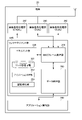
- FIG. 1 is a diagram showing an example of a configuration of a wireless system according to an embodiment.
- FIG. 2 is a diagram showing a specific example of the format of the MAC frame.
- FIG. 3 is a diagram showing an example of the configuration of a base station.
- FIG. 4 is a diagram showing an example of the functional configuration of the base station.
- FIG. 5 is a diagram showing an example of the configuration of the terminal.
- FIG. 6 is a diagram showing an example of the functional configuration of the terminal.
- FIG. 7 is a diagram showing details of a channel access function in a base station.
- FIG. 8 is a flowchart showing an example of multi-link processing in the wireless system according to the embodiment.
- FIG. 9 is a diagram showing an example of link management information.
- FIG. 1 is a diagram showing an example of a configuration of a wireless system according to an embodiment.
- FIG. 2 is a diagram showing a specific example of the format of the MAC frame.
- FIG. 3 is a diagram
- FIG. 10 is a diagram showing an example of association information between the TID and the primary link further included in the link management information.
- FIG. 11 is a flowchart showing an example of wireless signal transmission processing in a wireless system.
- FIG. 12 is a flowchart showing an example of wireless signal reception processing in a wireless system.
- FIG. 1 shows an example of the configuration of the wireless system 1 according to the embodiment.
- the wireless system 1 includes, for example, a base station 10, a terminal 20, and a server 30.
- the base station 10 is connected to the network NW and is used as a wireless LAN access point.
- the base station 10 can wirelessly transmit the data received from the network NW to the terminal 20.
- the base station 10 may be connected to the terminal 20 using one channel or a plurality of different channels.
- the wireless connection between the base station 10 and the terminal 20 using a plurality of different channels is referred to as "multi-link".
- Communication between the base station 10 and the terminal 20 is based on, for example, the 802.11 standard.
- the terminal 20 is a wireless terminal such as a smartphone or a tablet PC.
- the terminal 20 can send and receive data to and from the server 30 on the network NW via the base station 10 wirelessly connected.
- the terminal 20 may be another electronic device such as a desktop computer or a laptop computer.
- the terminal 20 may be capable of communicating with at least the base station 10.
- the server 30 can hold various information, for example, holds content data for the terminal 20.
- the server 30 is connected to, for example, a network NW by wire, and is configured to be able to communicate with the base station 10 via the network NW.
- the server 30 may be capable of communicating with at least the base station 10. That is, the communication between the base station 10 and the server 30 may be wired or wireless.
- the data communication between the base station 10 and the terminal 20 is based on the OSI (Open Systems Interconnection) reference model.
- the communication function has 7 layers (1st layer: physical layer, 2nd layer: data link layer, 3rd layer: network layer, 4th layer: transport layer, 5th layer: session layer, 6th layer. Layer: presentation layer, 7th layer: application layer).
- the data link layer includes, for example, an LLC (Logical Link Control) layer and a MAC (Media Access Control) layer.
- an LLC packet is formed by adding a DSAP (Destination Service Access Point) header, a SSAP (Source Service Access Point) header, or the like to data input from a higher-level application.
- a MAC frame is formed by adding a MAC header to an LLC packet.
- FIG. 2 shows a specific example of the format of the MAC frame used in the communication between the base station 10 and the terminal 20 in the wireless system 1 according to the embodiment.
- the fields included in the MAC frame include, for example, a Frame Control field, a Duration field, an Address1 field, an Address2 field, an Address3 field, a SequenceControl field, an Address4 field, a QoS Control field, an HTControl field, and a FrameBody field. , And FCS (Frame Check Sequence) fields. These fields may or may not be included depending on the type of wireless frame.
- the Frame Control field to the HT Control field correspond to the MAC header.
- the Frame Body field corresponds to the MAC payload.
- the FCS field stores an error detection code between the MAC header and the Frame Body field. The FCS field is used to determine the presence or absence of an error in the MAC frame.
- the Frame Control field contains various control information such as Type value, Subtype value, ToDS (DistributionSystem) value, FromDS value and Retry value.
- the Type value indicates whether the MAC frame is a management frame, a control frame, or a data frame.
- the Subtype value indicates the frame type of the MAC frame when used in combination with the Type value. For example, "00/1000 (Type value / Subtype value)" indicates that the MAC frame is a beacon signal. In addition, “00/0100 (Type value / Subtype value)” indicates that the MAC frame is a probe request. Further, “00/0101 (Type value / Subtype value)” indicates that the MAC frame is a probe response.
- the To DS value and From DS value have different meanings depending on the combination. For example, when the MAC frame is a data frame, the ToDS value “0” indicates that the receiving station is a terminal, and “1” indicates that the receiving station is a base station. Further, when the MAC frame is a data frame, the FromDS value “0” indicates that the transmitting station is a terminal, and “1” indicates that the transmitting station is a base station. On the other hand, the To DS value and From DS value when the MAC frame is a management frame or a control frame are fixed to, for example, “0”.
- the Retry value indicates whether or not the MAC frame is a retransmission frame. For example, a Retry value “0” indicates that the MAC frame is not a retransmission frame, that is, it is an original MAC frame. On the other hand, the Retry value "1" indicates that the MAC frame is a retransmission frame.
- the Duration field indicates the planned period for using the wireless line.
- the Address field indicates a BSSID, a source MAC address, a destination MAC address, a sender terminal address, a receiver terminal address, and the like. The number of Address fields used depends on the frame type.
- the SequenceControl field indicates the sequence number of the MAC frame and the fragment number for the fragment.
- the QoS Control field is used for the QoS (Quality of Service) function in the MAC frame.
- the QoS Control field may include a Traffic Type (TID) subfield.
- the HTControl field is a Control field for high throughput functions.
- the FrameBody field contains information according to the frame type. For example, when the frame type is a data frame, the transmission data is stored in the Frame Body field.
- FIG. 3 shows an example of the configuration of the base station 10.
- the base station 10 includes, for example, a CPU (Central Processing Unit) 11, a ROM (Read Only Memory) 12, a RAM (Random Access Memory) 13, a wireless communication module 14, and a wired communication module 15. There is.
- a CPU Central Processing Unit
- ROM Read Only Memory
- RAM Random Access Memory
- the CPU 11 is a circuit capable of executing various programs, and controls the overall operation of the base station 10.
- the ROM 12 is a non-volatile semiconductor memory, and holds a program, control data, and the like for controlling the base station 10.
- the RAM 13 is, for example, a volatile semiconductor memory and is used as a working area of the CPU 11.
- the wireless communication module 14 is a circuit used for transmitting and receiving data by a wireless signal, and is connected to an antenna. Further, the wireless communication module 14 includes, for example, a plurality of communication modules corresponding to a plurality of frequency bands.
- the wired communication module 15 is a circuit used for transmitting and receiving data by a wired signal, and is connected to a network NW.
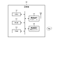
- FIG. 4 shows an example of the functional configuration of the base station 10.
- the base station 10 includes, for example, a data processing unit 100, a MAC frame processing unit 110, a management unit 120, and radio signal processing units 130, 140, and 150.
- the processing of the data processing unit 100, the MAC frame processing unit 110, the management unit 120, and the wireless signal processing units 130, 140, and 150 is realized by, for example, the CPU 11 and the wireless communication module 14.
- the data processing unit 100 can execute the processing of the LLC layer and the processing of the upper layer (third layer to the seventh layer) with respect to the input data. For example, the data processing unit 100 outputs the data input from the server 30 via the network NW to the MAC frame processing unit 110. Further, the data processing unit 100 transmits the data input from the MAC frame processing unit 110 to the server 30 via the network NW.
- the MAC frame processing unit 110 executes, for example, processing of the MAC layer on the input data. For example, the MAC frame processing unit 110 generates a MAC frame from the data input from the data processing unit 100. Further, the MAC frame processing unit 110 restores data from the MAC frames input from each of the radio signal processing units 130, 140, and 150. The process of generating a MAC frame from data and the process of restoring data from a MAC frame may be based on the 802.11 standard. Further, when the traffic type of the input data is a specific type, the MAC frame processing unit 110 duplicates the input data and generates a MAC frame based on the duplicated data. A specific type is, for example, RTA (Real-Time Application) traffic with an absolute delay requirement.
- RTA Real-Time Application
- the MAC frame processing unit 110 When a MAC frame is generated based on the duplicated data, the MAC frame processing unit 110 gives the MAC frame identification information as to whether or not the generated MAC frame is based on the duplicated data. Further, when the input MAC frame is duplicated, the MAC frame processing unit 110 selects one of the original and duplicate MAC frames to restore the data.
- the management unit 120 manages the link with the terminal 20 based on the notification received from the radio signal processing units 130, 140 and 150 via the MAC frame processing unit 110.
- the management unit 120 includes the link management information 121.
- the link management information 121 includes, for example, information of a terminal 20 stored in the RAM 13 and wirelessly connected to the base station 10.
- the management unit 120 includes an association processing unit 122 and an authentication processing unit 123.
- the association processing unit 122 executes the protocol related to the association when the connection request of the terminal 20 is received via any of the radio signal processing units 130, 140, and 150.
- the authentication processing unit 123 executes a protocol related to authentication following the connection request.
- the set of the data processing unit 100, the MAC frame processing unit 110, and the management unit 120 will be referred to as a link management unit LM1 of the base station 10.
- Each of the wireless signal processing units 130, 140 and 150 transmits and receives data between the base station 10 and the terminal 20 using wireless communication.
- each of the radio signal processing units 130, 140, and 150 creates a radio frame by adding a preamble, a PHY header, or the like to the MAC frame input from the MAC frame processing unit 110. Then, each of the radio signal processing units 130, 140, and 150 converts the radio frame into a radio signal and distributes the radio signal via the antenna of the base station 10. Further, each of the radio signal processing units 130, 140, and 150 converts the radio signal received via the antenna of the base station 10 into a radio frame. Then, each of the radio signal processing units 130, 140, and 150 outputs the data (for example, MAC frame) contained in the radio frame to the MAC frame processing unit 110.
- data for example, MAC frame
- each of the radio signal processing units 130, 140, and 150 can execute, for example, a part of the processing of the MAC layer and the processing of the first layer on the input data or the radio signal.
- the radio signal processing unit 130 handles a radio signal in the 2.4 GHz band.
- the radio signal processing unit 140 handles radio signals in the 5 GHz band.
- the radio signal processing unit 150 handles a radio signal in the 6 GHz band.
- the radio signal processing units 130, 140 and 150 may or may not share the antenna of the base station 10.
- FIG. 5 shows an example of the configuration of the terminal 20.
- the terminal 20 includes, for example, a CPU 21, a ROM 22, a RAM 23, a wireless communication module 24, a display 25, and a storage 26.
- the CPU 21 is a circuit capable of executing various programs, and controls the overall operation of the terminal 20.
- the ROM 22 is a non-volatile semiconductor memory, and holds a program, control data, and the like for controlling the terminal 20.
- the RAM 23 is, for example, a volatile semiconductor memory and is used as a working area of the CPU 21.
- the wireless communication module 24 is a circuit used for transmitting and receiving data by a wireless signal, and is connected to an antenna. Further, the wireless communication module 24 includes, for example, a plurality of communication modules corresponding to a plurality of frequency bands.
- the display 25 displays, for example, a GUI (Graphical User Interface) corresponding to the application software.
- the display 25 may have a function as an input interface of the terminal 20.
- the storage 26 is a non-volatile storage device, and holds, for example, the system software of the terminal 20.
- the terminal 20 does not have to have a display.
- FIG. 6 shows an example of the functional configuration of the terminal 20 included in the wireless system 1 according to the embodiment.
- the terminal 20 includes, for example, a data processing unit 200, a MAC frame processing unit 210, a management unit 220, a radio signal processing unit 230, 240 and 250, and an application execution unit 260.
- the processing of the data processing unit 200, the MAC frame processing unit 210, the management unit 220, and the wireless signal processing units 230, 240, and 250 is realized by, for example, the CPU 21 and the wireless communication module 24.
- the processing of the application execution unit 260 is realized by, for example, the CPU 21.
- the data processing unit 200 can execute the processing of the LLC layer and the processing of the upper layer (third layer to the seventh layer) with respect to the input data. For example, the data processing unit 200 outputs the data input from the application execution unit 260 to the MAC frame processing unit 210. Further, the data processing unit 200 outputs the data input from the MAC frame processing unit 210 to the application execution unit 260.
- the MAC frame processing unit 210 executes, for example, processing of the MAC layer on the input data.
- the MAC frame processing unit 210 generates a MAC frame from the data input from the data processing unit 200. Further, the MAC frame processing unit 210 restores data from the MAC frames input from the radio signal processing units 230, 240, and 250, respectively.
- the process of generating a MAC frame from data and the process of restoring data from a MAC frame may be based on the 802.11 standard.
- the traffic type of the input data is a specific type
- the MAC frame processing unit 210 duplicates the input data and generates a MAC frame based on the duplicated data.
- a particular type is, for example, RTA traffic.
- the MAC frame processing unit 210 When generating a MAC frame based on the duplicated data, the MAC frame processing unit 210 gives the MAC frame identification information as to whether or not the MAC frame is based on the duplicated data. Further, when the input MAC frame is duplicated, the MAC frame processing unit 210 selects one of the original and duplicate MAC frames to restore the data.
- the management unit 220 manages the link with the base station 10 based on the notification received from the radio signal processing units 230, 240 and 250 via the MAC frame processing unit 210.
- the management unit 220 includes the link management information 221.
- the link management information 221 contains information on the base station 10 stored in the RAM 23, for example, and wirelessly connected to the terminal 20.
- the management unit 220 includes an association processing unit 222 and an authentication processing unit 223.
- the association processing unit 222 executes the protocol related to the association when the connection request of the base station 10 is received via any of the radio signal processing units 230, 240, and 250.
- the authentication processing unit 223 executes a protocol related to authentication following the connection request.
- the set of the data processing unit 200, the MAC frame processing unit 210, and the management unit 220 will be referred to as a link management unit LM2 of the terminal 20.
- Each of the wireless signal processing units 230, 240, and 250 transmits and receives data between the base station 10 and the terminal 20 using wireless communication.
- each of the radio signal processing units 230, 240, and 250 creates a radio frame by adding a preamble, a PHY header, or the like to the MAC frame input from the MAC frame processing unit 210.
- each of the wireless signal processing units 230, 240, and 250 converts the wireless frame into a wireless signal and distributes the wireless signal via the antenna of the terminal 20.
- each of the wireless signal processing units 230, 240, and 250 converts the wireless signal received via the antenna of the terminal 20 into a wireless frame.
- each of the radio signal processing units 230, 240, and 250 outputs the data (for example, MAC frame) included in the radio frame to the MAC frame processing unit 210.
- each of the radio signal processing units 230, 240, and 250 can execute, for example, a part of the processing of the MAC layer and the processing of the first layer on the input data or the radio signal.
- the radio signal processing unit 230 handles a radio signal in the 2.4 GHz band.
- the radio signal processing unit 240 handles radio signals in the 5 GHz band.
- the radio signal processing unit 250 handles a radio signal in the 6 GHz band.
- the wireless signal processing units 230, 240 and 250 may or may not share the antenna of the terminal 20.
- the application execution unit 260 executes an application that can use the data input from the data processing unit 200. For example, the application execution unit 260 can display the information of the application on the display 25. Further, the application execution unit 260 may operate based on the operation of the input interface.
- the wireless signal processing units 130, 140 and 150 of the base station 10 are configured to be connectable to the wireless signal processing units 230, 240 and 250 of the terminal 20, respectively. That is, the wireless signal processing units 130 and 230 can be wirelessly connected using the 2.4 GHz band.
- the wireless signal processing units 140 and 240 may be wirelessly connected using the 5 GHz band.
- the wireless signal processing units 150 and 250 may be wirelessly connected using the 6 GHz band.
- each radio signal processing unit may be referred to as a “STA function”. That is, the wireless system 1 according to the embodiment has a plurality of STA functions.
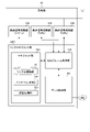
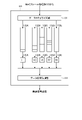
- FIG. 7 shows the details of the channel access function in the radio signal processing unit of the base station 10.
- the radio signal processing units 130, 140 and 150 each have a channel access function.
- FIG. 7 shows the channel access function of the radio signal processing unit 130.
- the channel access functions of the radio signal processing units 140 and 150 are the same as the channel access functions of the radio signal processing unit 130. Therefore, the description of the channel access function of the radio signal processing units 140 and 150 will be omitted.
- the wireless signal processing units 230, 240 and 250 of the terminal 20 also have channel access functions, respectively.
- the channel access functions of the radio signal processing units 230, 240 and 250 are the same as the channel access functions of the radio signal processing unit 130. Therefore, the description of the channel access function of the radio signal processing units 230, 240, and 250 will be omitted.
- the channel access function includes, for example, data categorization unit 131, transmission queue 132A, 132B, 132C, 132D and 132E, CSMA / CA (Carrier Sense Multiple Access with Collision Avoidance) execution unit 133A, 133B, 133C, It includes 133D and 133E, and a data collision management unit 134.
- the channel access function is realized by using EDCA (Enhanced Distribution Channel Access).
- the data categorization unit 131 categorizes the MAC frame data input from the MAC frame processing unit 110 using, for example, a TID.
- the TID is given for each application (session) handled by the terminal 20, and represents the type of traffic.
- As the data category for example, "LL (Low Latency)", “VO (Voice)”, “VI (Video)”, “BE (Best Effort)", and “BK (Background)” are set. LL is applied to data corresponding to RTA traffic that requires low delay. It is preferable that the LL data is processed in preference to any of the VO, VI, BE and BK data.
- the data categorization unit 131 inputs the MAC frame containing the categorized data to any of the transmission queues 132A, 132B, 132C, 132D and 132E.
- a MAC frame containing LL data is input to the transmission queue 132A.
- a MAC frame containing VO data is input to the transmission queue 132B.
- a MAC frame containing VI data is input to the transmission queue 132C.
- a MAC frame containing BE data is input to the transmission queue 132D.
- the MAC frame containing the BK data is input to the transmission queue 132E.
- each of the input MAC frames is stored in any of the corresponding transmission queues 132A to E.
- Each of the CSMA / CA execution units 133A, 133B, 133C, 133D and 133E has the access parameters set in advance while confirming that the radio signal is not transmitted by other terminals or the like by the carrier sense in the CSMA / CA. Wait for transmission for the specified time. Then, when the CSMA / CA execution unit 133A, 133B, 133C, 133D and 133E can acquire the transmission right, they take out the MAC frame from the corresponding transmission queues 132A, 132B, 132C, 132D and 132E, and take out the taken out MAC frame. It is output to the STA function via the data collision management unit 134. Then, the STA function of the wireless signal processing unit 130 generates a wireless signal based on the input MAC frame, and the wireless signal is transmitted.
- the CSMA / CA execution unit 133A executes CSMA / CA for a MAC frame containing LL data held in the transmission queue 132A.
- the CSMA / CA execution unit 133B executes CSMA / CA for a MAC frame containing VO data held in the transmission queue 132B.
- the CSMA / CA execution unit 133C executes CSMA / CA for a MAC frame containing VI data held in the transmission queue 132C.
- the CSMA / CA execution unit 133D executes CSMA / CA for a MAC frame containing BE data held in the transmission queue 132D.
- the CSMA / CA execution unit 133E executes CSMA / CA for a MAC frame containing BK data held in the transmission queue 132E.
- Access parameters are assigned so that transmission of radio signals is prioritized in the order of, for example, LL, VO, VI, BE, and BK.
- Access parameters include, for example, CWmin, CWmax, AIFS, TXOPLimit.
- CWmin and CWmax indicate the minimum value and the maximum value of the contention window CW (ContentionWindow), which is the transmission waiting time for collision avoidance, respectively.
- AIFS Aribitration InterFrame Space
- TXOPLimit indicates an upper limit value of TXOP (Transmission Opportunity) corresponding to the occupation time of the channel. For example, the shorter the CWmin and CWmax of the transmission queue, the easier it is to obtain transmission rights.
- the lower the AIFS the higher the priority of the send queue. The amount of data transmitted with one transmission right increases as the value of TXOP Limit increases.
- the data collision management unit 134 prevents data collisions when a plurality of CSMA / CA execution units acquire transmission rights with the same STA function. Specifically, the data collision management unit 134 adjusts the transmission timing of data for which transmission rights have been acquired by the same STA function in different categories, and changes from a MAC frame containing data in a high priority category to an STA function. Send. For example, the STA function acquired the transmission right by the CSMA / CA of the transmission queue 132A of the LL acquires the transmission right at the same time as the STA function acquired the transmission right by the CSMA / CA of any of the other transmission queues 132B to 132E. In some cases.
- the data collision management unit 134 preferentially transmits the MAC frame stored in the transmission queue 132A to the STA function. Similarly, in the other combinations of transmission queues 132B to 132E, MAC frames are transmitted in the order based on the priority set in the category. This prevents collisions between data to which transmission is assigned to the same STA function.
- the above channel access function may be implemented in the link management unit LM1 instead of the radio signal processing units 130, 140, 150.
- each STA function may independently execute carrier sense and transmit data.
- the channel access when a plurality of links are used at the same time may be executed by standardizing the access parameters by exchanging between the plurality of STA functions, and the access parameters are standardized by the link management unit. It may be executed by.
- the base station 10 and the terminal 20 can use a plurality of links at the same time by transmitting data among the plurality of STA functions based on common access parameters.
- each radio signal processing unit detects the state (idle / busy) of the radio channel in the corresponding link, and the link management unit uses which link. Determine whether to send data such as whether to send.
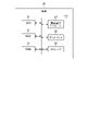
- the base station 10 and the terminal 20 shall establish a multilink with the two STA functions STA1 and STA2, respectively.
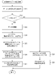
- FIG. 8 is a flowchart showing an example of multi-link processing in the wireless system 1 according to the embodiment. As shown in FIG. 8, in the multi-link process, for example, the processes of steps S10 to S16 are executed in order.
- the terminal 20 transmits a probe request to the base station 10.
- the probe request is a signal for confirming whether or not the base station 10 exists in the vicinity of the terminal 20.
- the Frame Control field of the probe request contains, for example, "00/0100 (Type value / Subtype value)".
- the base station 10 executes the process of step S11.
- the base station 10 transmits a probe response to the terminal 20.
- the probe response is a signal used by the base station 10 to respond to a probe request from the terminal 20.
- the Frame Control field of the probe response contains, for example, "00/0101 (Type value / Subtype value)".
- the terminal 20 executes the process of step S12.
- the terminal 20 transmits a multi-link association request to the base station 10 via at least one STA function.
- the multi-link association request is a signal for requesting the base station 10 to establish a multi-link.
- the multi-link association request is generated by the management unit 220 of the terminal 20.
- the Frame Control field of the multi-link association request contains, for example, "00/0000 (Type value / Subtype value)".
- the management unit 120 of the base station 10 executes the process of step S13.
- the management unit 120 of the base station 10 executes the multi-link association process using one STA function. Specifically, first, the base station 10 executes the association processing of the first STA function with the terminal 20. Then, when the wireless connection (link) is established in the first STA function, the management unit 120 of the base station 10 uses the first STA function in which the link is established to use the second STA. Executes function association processing. That is, the STA function with an established link is used for the association processing of the STA function with no established link. When the association processing of at least two STA functions is completed, the base station 10 establishes the multi-link and executes the processing of step S14.
- the multi-link may be established when the link is established in the first STA function.
- each of the base station 10 and the terminal 20 notifies the capability of the multi-link, the link to be the target of the multi-link, the operation parameter in each link, etc. prior to the association processing, so that the base station 10 and the terminal 20 can perform the multi-link.
- Associations can be executed in bulk.
- the management units 120 and 220 instruct the establishment of the multi-link when the first STA function starts the association, and specify the link or the like to be the target of the multi-link. Then, the management units 120 and 220 execute the association of the links, respectively, and manage these links as a multi-link.
- step S14 the management unit 120 of the base station 10 updates the link management information 121.
- the process of step S14 is executed after the two links are established, but the link management information 121 may be updated every time the link state is updated, or the multi-link is established. It may be updated at the time.
- the base station 10 executes the process of step S15.
- the base station 10 transmits a multi-link establishment response to the terminal 20.
- the multi-link establishment response is a signal used by the base station 10 to respond to a multi-link request from the terminal 20.
- the Frame Control field of the multi-link establishment response contains, for example, "00/0001 (Type value / Subtype value)".
- the management unit 220 of the terminal 20 recognizes that the multi-link with the base station 10 has been established based on the reception of the multi-link establishment response.
- the terminal 20 executes the process of step S16.
- step S16 the management unit 220 of the terminal 20 updates the link management information 221. That is, the terminal 20 records in the link management information 221 that the multi-link with the base station 10 has been established. As a result, the setup of the multi-link in the wireless system 1 according to the embodiment is completed, and the data communication using the multi-link becomes possible between the base station 10 and the terminal 20.
- FIG. 9 shows an example of the link management information 121. Since the link management information 221 of the terminal 20 has information similar to the link management information 121 of the base station 10, the description thereof will be omitted. As shown in FIG. 9, the link management information 121 includes, for example, STA function, frequency band, link destination ID, presence / absence of multilink, and TID.
- STA1 corresponds to the STA function using the frequency band of 6 GHz, that is, the radio signal processing unit 150 or 250.
- STA2 corresponds to the STA function using the frequency band of 5 GHz, that is, the radio signal processing unit 140 or 240.
- STA3 corresponds to the STA function using the frequency band of 2.4 GHz, that is, the radio signal processing unit 130 or 230.
- the link destination ID represents the identifier of the terminal 20 in the link management information 121, and represents the identifier of the base station 10 in the link management information 221.
- FIG. 9 shows an example in which a multi-link using STA1 and STA2 is established.
- TID indicates the association between the STA function and TID.
- Each STA function sends and receives data corresponding to the associated TID.
- TID # 1 is a TID of RTA traffic and corresponds to LL.
- TIDs # 2 and # 3 correspond to any of VO, VI, BE, and BK other than LL.
- a plurality of STA functions are associated with RTA traffic, that is, TID # 1.
- one STA function may be associated with traffic other than RTA traffic, that is, TIDs # 2 and # 3, or a plurality of STA functions may be associated with each other.
- one STA function is associated with TIDs # 2 and # 3.
- FIG. 10 shows an example of the association information between the TID and the primary link further included in the link management information 121.
- the primary link is the link used as the main link in the multilink.
- a secondary link is a link used as an auxiliary link in a multilink.
- STA1 and STA2 are associated with TID # 1.
- STA1 or STA2 are associated with the primary link.
- STA1 is associated with the primary link and STA2 is associated with the secondary link. Only one STA function is associated with TIDs # 2 and # 3. In this case, the association information between the TID and the primary link is not set.
- each of the MAC frame processing units 110 and 210 duplicates the input data when the data corresponding to RTA traffic, that is, TID # 1 is input. Then, each of the MAC frame processing units 110 and 210 outputs the MAC frame containing the original data of the duplication source to the STA1 which is the primary link, and uses the MAC frame including the duplication data as the MAC frame for retransmission as the secondary link. It is output to STA2. That is, in the embodiment, for the RTA traffic, the data for retransmission is transmitted in advance without waiting for the retransmission request from the transmission destination.
- each of the MAC frame processing units 110 and 210 outputs the data to the STA associated with the TID when the data corresponding to the data other than the RTA traffic, that is, TID # 2 or # 3 is input.
- the link sets constituting the multilink may be different from each other for each terminal 20 that establishes the multilink with the base station 10, and the primary link may also be different. They may be different from each other.
- the optimum link between the base station 10 and each terminal 20 can be set as the primary link. This is expected to have the effect of improving the quality of wireless communication.
- the primary link may be used for sending and receiving control information related to the operation of the multi-link, in addition to sending and receiving the assigned data.
- the primary link may be preset, for example, when establishing a multilink between the base station 10 and the terminal 20.
- the STA function used as the primary link may be set in priority according to the frequency band or may be set according to the radio field strength of the link.
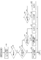
- FIG. 11 is a flowchart showing an example of wireless signal transmission processing in the wireless system 1.
- the base station 10 is a transmitting station that transmits a radio signal.
- the process of FIG. 11 is started, for example, when data from a higher-level server 30 is input to the MAC frame processing unit 110 via the data processing unit 100.
- the multi-link setup between the base station 10 and the terminal 20 has been completed. That is, it is assumed that the link management information 121 shown in FIGS. 9 and 10 is set.
- step S21 the MAC frame processing unit 110 acquires the TID corresponding to the input data.
- step S22 the MAC frame processing unit 110 determines whether or not the input data is data corresponding to RTA traffic based on the acquired TID. When it is determined in step S22 that the input data corresponds to RTA traffic, the process proceeds to step S23. When it is determined in step S22 that the input data is not data corresponding to RTA traffic, the process proceeds to step S28.
- step S23 the MAC frame processing unit 110 duplicates the input data.
- two or more replicas may be generated. When two or more copies are generated, it is necessary to establish a multi-link using three or more STA functions between the base station 10 and the terminal.
- step S24 the MAC frame processing unit 110 generates a MAC frame from the input original data. Further, the MAC frame processing unit 110 generates a MAC frame from the duplicated data.
- the MAC frame based on these original data and the MAC frame based on the duplicated data are the same except that the identification information described later is different. That is, the original MAC frame based on the original data and the duplicate MAC frame based on the duplicate data have the same sequence number.
- the MAC frame processing unit 110 assigns identification information to each of the original MAC frame and the duplicate MAC frame.
- the identification information is information indicating whether or not the MAC frame is based on the duplicated data.
- the duplicated data is used as data for retransmission. Therefore, the above-mentioned Retry value can be used as the identification information. For example, "0" is added to the Retry value of the original MAC frame. In addition, "1" is added to the Retry value of the duplicate MAC frame used for retransmission. This is true even if there are two or more duplicate MAC frames. With such identification information, the original MAC frame and the duplicate MAC frame can be distinguished among a plurality of MAC frames having the same sequence number.
- the identification information may be added as an extended MAC header using a reserved bit.
- the identification information has two types of information: information indicating whether or not the MAC frame has a copy, and information indicating whether the MAC frame is an original MAC frame or a duplicate MAC frame. May have.
- the Retry value can be used for the information indicating whether the MAC frame is the original MAC frame or the duplicate MAC frame.
- step S26 the MAC frame processing unit 110 outputs the original MAC frame to the STA function (radio signal processing unit) of the primary link of the corresponding TID, and outputs the duplicate MAC frame to the STA function of the secondary link of the corresponding TID. ..
- the MAC frame processing unit 110 may output the original MAC frame and the duplicate MAC frame to different primary links. That is, in step S26, the original MAC frame and the duplicate MAC frame may be output to different STA functions.
- step S27 the STA function of each link transmits a radio signal using EDCA based on CSMA / CA. After that, the process of FIG. 11 ends.
- the STA function of each link independently transmits a radio signal using EDCA.
- the STA function of each link may transmit radio signals in parallel while coordinating channel access.
- the MAC frame processing unit 110 controls the channel access function so that the wireless signals can be transmitted in parallel based on the CSMA / CA notification from the STA function of each link. You may. Further, the MAC frame processing unit 110 may notify the STA function of each link of the common access parameter, and cause the STA function to transmit a radio signal using the EDCA.
- step S28 the MAC frame processing unit 110 generates a MAC frame from the input data. Then, the MAC frame processing unit 110 outputs the generated MAC frame to the STA function of the corresponding link.
- step S29 the STA function transmits a radio signal using EDCA based on CSMA / CA. After that, the process of FIG. 11 ends.
- FIG. 12 is a flowchart showing an example of wireless signal reception processing in the wireless system 1.
- the terminal 20 is a receiving station that receives a radio signal.
- the process of FIG. 12 is started when a MAC frame from each STA function is input to the MAC frame processing unit 210.
- step S31 the MAC frame processing unit 210 rearranges the input MAC frames in the order of the sequence number.
- step S32 the MAC frame processing unit 210 determines whether or not the input MAC frame is duplicated. Whether or not there is duplication can be determined from, for example, whether or not there are MAC frames having the same sequence number. When it is determined in step S32 that there is duplication, that is, both the original MAC frame and the duplicate MAC frame have been received, the process proceeds to step S33. When it is determined in step S32 that there is no duplication, the process proceeds to step S38.
- step S33 the MAC frame processing unit 210 determines whether or not the original MAC frame has been correctly received.
- the original MAC frame and the duplicate MAC frame are distinguished by, for example, the Retry value. Further, whether or not the MAC frame can be correctly received can be determined by the FCS.
- step S34 the process proceeds to step S34.
- step S35 the process proceeds to step S35.
- step S34 the MAC frame processing unit 210 selects the original MAC frame and discards all the duplicate MAC frames. After that, the process of FIG. 12 ends. After the processing of FIG. 12, data is restored from the MAC frame, and this data is used by a higher-level application or the like.
- step S35 the MAC frame processing unit 210 determines whether or not any duplicate MAC frame has been correctly received. When it is determined in step S35 that the MAC frame of any of the duplicates has been correctly received, the process proceeds to step S36. When it is determined in step S35 that none of the duplicate MAC frames have been correctly received, the process proceeds to step S37.
- step S36 the MAC frame processing unit 210 selects one of the duplicated MAC frames that have been correctly received, and discards the original MAC frame and the remaining duplicated MAC frames. After that, the process of FIG. 12 ends. After the processing of FIG. 12, data is restored from the MAC frame, and this data is used by a higher-level application or the like.
- the number of replica MAC frames correctly received in step S36 is two or more, which replica MAC frame should be selected can be appropriately determined. For example, if a priority is given between the STA functions, the MAC frame processing unit 210 may select a MAC frame to be left according to the priority. The priority may be fixed or may be changed according to the result of carrier sense or the like. The priority information may be included in the duplicate MAC frame.
- step S37 the MAC frame processing unit 210 makes a retransmission request to the base station 10.
- Retransmission may be performed using the primary link or may be performed using the secondary link. Further, the retransmission request may be made in the form of block ACK.
- the process of FIG. 12 ends.
- the radio signal is retransmitted from the base station 10.
- the retransmission request is made only when both the reception of the original data and the reception of the duplicated data fail.
- step S38 the MAC frame processing unit 210 determines whether or not the input MAC frame can be correctly received. When it is determined in step S38 that the input MAC frame has been correctly received, the process proceeds to step S39. When it is determined in step S38 that the input MAC frame has not been correctly received, the process proceeds to step S40.
- step S39 the MAC frame processing unit 210 selects the input MAC frame. After that, the process of FIG. 12 ends. After the processing of FIG. 12, data is restored from the MAC frame, and this data is used by a higher-level application or the like.
- step S40 the MAC frame processing unit 210 makes a retransmission request to the base station 10.
- Retransmission may be performed using the primary link or may be performed using the secondary link. Further, the retransmission request may be made in the form of block ACK.
- the process of FIG. 12 ends. After the processing of FIG. 12, the radio signal is retransmitted from the base station 10.
- the transmission timing of the original MAC frame and the duplicate MAC frame may be different depending on the channel status of each link. There is. In this case, if it is known from the identification information that there is a copy, the receiving station may wait for the reception of the original MAC frame and the duplicate MAC frame and then perform the same process as in FIG. However, the original MAC frame and the duplicate MAC frame, whichever is correctly received first, may be left, and the later received one may be discarded.
- the link diversity transmits the data for retransmission prior to the retransmission request from the receiving station. Therefore, the delay associated with the retransmission is suppressed as compared with the case where the retransmission is performed in response to the retransmission request from the receiving station.
- the receiving station receives the same data almost at the same time.
- the original data is given identification information indicating that it is original
- the duplicated data is given identification information indicating that it is duplicated, so that the receiving station can use the original data. It can be correctly identified and processed from the duplicated data.
- the base station 10 is a transmitting station that transmits a radio signal
- the terminal 20 is a receiving station that receives the radio signal.
- the technique of the embodiment can be applied even in a situation where the terminal 20 transmits a radio signal and the base station 10 receives the radio signal. That is, the relationship between the transmitting station and the receiving station described in the embodiment can be exchanged.
- the STA function is configured to transmit and receive radio signals using channels in different frequency bands.
- the STA function may be configured to transmit and receive radio signals using different channels of the same frequency band.
- the radio signal processing unit 130 is configured to transmit a radio signal using the first channel in the 2.4 GHz band
- the radio signal processing unit 140 uses the second channel in the 2.4 GHz band. It may be configured to transmit a radio signal.
- the first channel and the second channel may each include a plurality of channels as long as they do not overlap.
- [Modification 3] it is determined by TID whether or not to duplicate the data for retransmission. However, if the data requires low delay, duplication of the data for retransmission may be performed without necessarily relying on the determination based on the TID.
- Each process according to the above-described embodiment can be stored as a program that can be executed by a CPU or the like which is a computer.
- it can be stored and distributed in a storage medium of an external storage device such as a magnetic disk, an optical disk, or a semiconductor memory.
- the CPU or the like can read the program stored in the storage medium of the external storage device, and the operation is controlled by the read program, so that the above-mentioned processing can be executed.
- the present invention is not limited to the above embodiment, and can be variously modified at the implementation stage without departing from the gist thereof.
- each embodiment may be carried out in combination as appropriate, in which case the combined effect can be obtained.
- the above-described embodiment includes various inventions, and various inventions can be extracted by a combination selected from a plurality of disclosed constituent requirements. For example, even if some constituent elements are deleted from all the constituent elements shown in the embodiment, if the problem can be solved and the effect is obtained, the configuration in which the constituent elements are deleted can be extracted as an invention.
- Wireless system 10 ... Base station 20 ... Terminal 30 ... Server 11,21 ... CPU 12, 22 ... ROM 13, 23 ... RAM 14, 24 ... Wireless communication module 15 ... Wired communication module 25 ... Display 26 ... Storage 100, 200 ... Data processing unit 110, 210 ... MAC frame processing unit 120, 220 ... Link management unit 121,221 ... Link management information 122, 222 ... ... Association processing unit 123, 223 ... Authentication processing unit 130, 140, 150, 230, 240, 250 ... Radio signal processing unit 131 ... Data categorization unit 132A, 132B, 132C, 132D, 132E ... Transmission queue 133A, 133B, 133C, 133D, 133E ... CSMA / CA (Carrier Sense Multiple Access with Collision Avoidance) Execution Unit 134 ... Data Collision Management Department
Abstract
実施形態の送信局は、第1の無線信号処理部(140)と、第2の無線信号処理部(150)と、リンクマネジメント部とを含む。第1の無線信号処理部と第2の無線信号処理部は、異なるチャネルを用いて無線信号を送信するように構成されている。リンクマネジメント部は、第1の無線信号処理部と第2の無線信号処理部のリンク状態を管理する。リンクマネジメント部は、入力された第1のデータが特定の種別のデータであるとき、第1のデータの複製である第2のデータを生成し、第1のデータにオリジナルのデータであることを示す第1の識別情報を付与するともに、第2のデータに複製のデータであることを示す第2の識別情報を付与し、第1の識別情報が付与された第1のデータを第1の無線信号処理部に出力するとともに、第2の識別情報が付与された第2のデータを無線信号処理部に出力する。
Description
実施形態は、送信局及び受信局に関する。
基地局と端末といった、無線信号を送信する送信局と無線信号を受信する受信局との間の無線システムとして、無線LAN(Local Area Network)が知られている。
IEEE Std 802.11-2016,"10.22.2 HCF contention based channel access (EDCA)", 7 December 2016
実施形態は、遅延に関する絶対的な要求条件を持つアプリケーションを利用できる送信局及び受信局を提供する。
実施形態では、送信局は、第1の無線信号処理部と、第2の無線信号処理部と、リンクマネジメント部とを備える。第1の無線信号処理部は、第1のチャネルを用いて無線信号を送信するように構成されている。第2の無線信号処理部は、第1のチャネルと異なる第2のチャネルを用いて無線信号を送信するように構成されている。リンクマネジメント部は、受信局と第1の無線信号処理部との間のリンク状態と、受信局と第2の無線信号処理部との間のリンク状態とを管理する。リンクマネジメント部は、入力された第1のデータが特定の種別のデータであるとき、第1のデータの複製である第2のデータを生成し、第1のデータにオリジナルのデータであることを示す第1の識別情報を付与するともに、第2のデータに複製のデータであることを示す第2の識別情報を付与し、第1の識別情報が付与された第1のデータを第1の無線信号処理部に出力するとともに、第2の識別情報が付与された第2のデータを第2の無線信号処理部に出力する。
実施形態によれば、遅延に関する絶対的な要求条件を持つアプリケーションを利用できる送信局及び受信局を提供することができる。
以下に、実施形態について図面を参照して説明する。図1は、実施形態に係る無線システム1の構成の一例を示している。図1に示すように、無線システム1は、例えば基地局10、端末20、及びサーバ30を備えている。
基地局10は、ネットワークNWに接続され、無線LANのアクセスポイントとして使用される。例えば、基地局10は、ネットワークNWから受信したデータを、無線で端末20に送信することができる。また、基地局10は、1つのチャネル又は複数の異なるチャネルを用いて、端末20に接続され得る。本明細書では、基地局10と端末20との間における複数の異なるチャネルを用いた無線接続のことを、“マルチリンク”と呼ぶ。基地局10と端末20との間の通信は、例えばIEEE802.11規格に基づいている。
端末20は、スマートフォンやタブレットPC等の無線端末である。端末20は、無線で接続された基地局10を介して、ネットワークNW上のサーバ30との間でデータを送受信することができる。端末20は、デスクトップコンピュータやラップトップコンピュータ等、その他の電子機器であってもよい。端末20は、少なくとも基地局10と通信可能であればよい。
サーバ30は、様々な情報を保持することが可能であり、例えば端末20を対象としたコンテンツのデータを保持している。サーバ30は、例えばネットワークNWに有線で接続され、ネットワークNWを介して基地局10と通信可能に構成される。サーバ30は、少なくとも基地局10と通信可能であればよい。つまり、基地局10とサーバ30との間の通信は、有線であっても無線であってもよい。
実施形態に係る無線システム1において、基地局10と端末20との間のデータ通信は、OSI(Open Systems Interconnection)参照モデルに基づいている。OSI参照モデルでは、通信機能が7階層(第1層:物理層、第2層:データリンク層、第3層:ネットワーク層、第4層:トランスポート層、第5層:セッション層、第6層:プレゼンテーション層、第7層:アプリケーション層)に分割される。また、データリンク層は、例えばLLC(Logical Link Control)層と、MAC(Media Access Control)層とを含んでいる。LLC層では、例えば上位のアプリケーションから入力されたデータに、DSAP(Destination Service Access Point)ヘッダやSSAP(Source Service Access Point)ヘッダ等が付加されることでLLCパケットが形成される。MAC層では、例えばLLCパケットにMACヘッダが付加されることでMACフレームが形成される。
図2は、実施形態に係る無線システム1において、基地局10及び端末20間の通信で使用されるMACフレームのフォーマットの具体例を示している。図2に示すように、MACフレームに含まれるフィールドとして、例えばFrame Controlフィールド、Durationフィールド、Address1フィールド、Address2フィールド、Address3フィールド、Sequence Controlフィールド、Address4フィールド、QoS Controlフィールド、HT Controlフィールド、Frame Bodyフィールド、及びFCS(Frame Check Sequence)フィールドがある。これらのフィールドは、無線フレームの種類により含まれるものと含まれないものがある。
Frame ControlフィールドからHT Controlフィールドまでは、MACヘッダに対応している。Frame Bodyフィールドは、MACペイロードに対応している。FCSフィールドは、MACヘッダとFrame Bodyフィールドとの誤り検出符号を格納している。FCSフィールドは、MACフレームにおけるエラーの有無の判定に使用される。
Frame Controlフィールドは、様々な制御情報、例えばType値、Subtype値、To DS(Distribution System)値、From DS値及びRetry値を含んでいる。
Type値は、そのMACフレームがマネージメントフレームであるのか、制御フレームであるのか、データフレームであるのかを示す。Subtype値は、Type値と組み合わせて使用されることでMACフレームのフレームタイプを示す。例えば、“00/1000(Type値/Subtype値)”は、そのMACフレームがビーコン信号であることを示す。また、“00/0100(Type値/Subtype値)”は、そのMACフレームがプローブリクエストであることを示す。また、“00/0101(Type値/Subtype値)”は、そのMACフレームがプローブレスポンスであることを示す。
To DS値及びFrom DS値は、その組み合わせにより異なる意味を有する。例えば、MACフレームがデータフレームであるときのTo DS値“0”は受信局が端末であることを示し、“1”は受信局が基地局であることを示す。また、MACフレームがデータフレームであるときのFrom DS値“0”は送信局が端末であることを示し、“1”は送信局が基地局であることを示す。一方、MACフレームがマネージメントフレーム又は制御フレームであるときのTo DS値及びFrom DS値は、例えば“0”に固定される。
Retry値は、そのMACフレームが再送フレームであるか否かを示す。例えば、Retry値“0”はそのMACフレームが再送フレームでない、すなわちオリジナルのMACフレームであることを示す。一方、Retry値“1”はそのMACフレームが再送フレームであることを示す。
Durationフィールドは、無線回線を使用する予定期間を示す。Addressフィールドは、BSSID、送信元MACアドレス、あて先MACアドレス、送信者端末のアドレス、受信者端末のアドレス等を示す。使用されるAddressフィールドの数は、フレームタイプによって変化する。Sequence Controlフィールドは、MACフレームのシーケンス番号と、フラグメントのためのフラグメント番号とを示す。QoS Controlフィールドは、MACフレームにおけるQoS(Quality of Service)機能に利用される。QoS Controlフィールドは、トラヒック種別(TID)サブフィールドを含んでいてよい。HT Controlフィールドは、高スループット機能のためのControl フィールドである。Frame Bodyフィールドは、フレームタイプに応じた情報を含んでいる。例えば、フレームタイプがデータフレームである場合のFrame Bodyフィールドには送信データが格納される。
図3は、基地局10の構成の一例を示している。図3に示すように、基地局10は、例えばCPU(Central Processing Unit)11、ROM(Read Only Memory)12、RAM(Random Access Memory)13、無線通信モジュール14、及び有線通信モジュール15を備えている。
CPU11は、様々なプログラムを実行することが可能な回路であり、基地局10の全体の動作を制御する。ROM12は、不揮発性の半導体メモリであり、基地局10を制御するためのプログラムや制御データ等を保持している。RAM13は、例えば揮発性の半導体メモリであり、CPU11の作業領域として使用される。無線通信モジュール14は、無線信号によるデータの送受信に使用される回路であり、アンテナに接続される。また、無線通信モジュール14は、例えば複数の周波数帯にそれぞれ対応する複数の通信モジュールを含んでいる。有線通信モジュール15は、有線信号によるデータの送受信に使用される回路であり、ネットワークNWに接続される。
図4は、基地局10の機能構成の一例を示している。図4に示すように、基地局10は、例えばデータ処理部100、MACフレーム処理部110、マネジメント部120、並びに無線信号処理部130、140及び150を備える。データ処理部100、MACフレーム処理部110、マネジメント部120、並びに無線信号処理部130、140及び150の処理は、例えばCPU11及び無線通信モジュール14によって実現される。
データ処理部100は、入力されたデータに対して、LLC層の処理と上位層(第3層~第7層)の処理とを実行し得る。例えば、データ処理部100は、ネットワークNWを介してサーバ30から入力されたデータを、MACフレーム処理部110に出力する。また、データ処理部100は、MACフレーム処理部110から入力されたデータを、ネットワークNWを介してサーバ30に送信する。
MACフレーム処理部110は、入力されたデータに対して、例えばMAC層の処理を実行する。例えば、MACフレーム処理部110は、データ処理部100から入力されたデータからMACフレームを生成する。また、MACフレーム処理部110は、無線信号処理部130、140、150のそれぞれから入力されたMACフレームからデータを復元する。データからMACフレームを生成する処理とMACフレームからデータを復元する処理とは、IEEE802.11規格に基づいていてよい。また、MACフレーム処理部110は、入力されたデータのトラヒック種別が特定の種別であるとき、入力されたデータを複製し、複製したデータに基づくMACフレームを生成する。特定の種別は、例えば絶対的な遅延の要求条件のあるRTA(Real-Time Application)トラヒックである。複製したデータに基づきMACフレームを生成するとき、MACフレーム処理部110は、生成したMACフレームが複製されたデータに基づくものであるか否かの識別情報をMACフレームに付与する。また、MACフレーム処理部110は、入力されたMACフレームに重複があるときには、オリジナルと複製のMACフレームのうちの1つを選択してデータを復元する。
マネジメント部120は、無線信号処理部130、140及び150からMACフレーム処理部110を介して受信した通知に基づいて、端末20とのリンクを管理する。マネジメント部120は、リンク管理情報121を含んでいる。リンク管理情報121は、例えばRAM13に格納され、基地局10に無線接続されている端末20の情報を含んでいる。また、マネジメント部120は、アソシエーション処理部122及び認証処理部123を含んでいる。アソシエーション処理部122は、無線信号処理部130、140及び150の何れかを介して端末20の接続要求を受信した場合に、アソシエーションに関するプロトコルを実行する。認証処理部123は、接続要求に続いて、認証に関するプロトコルを実行する。以下では、データ処理部100、MACフレーム処理部110及びマネジメント部120の組のことを、基地局10のリンクマネジメント部LM1と呼ぶ。
無線信号処理部130、140及び150のそれぞれは、無線通信を用いて基地局10と端末20との間のデータの送受信を行う。例えば、無線信号処理部130、140及び150のそれぞれは、MACフレーム処理部110から入力されたMACフレームにプリアンブルやPHYヘッダ等を付加して、無線フレームを作成する。そして、無線信号処理部130、140及び150のそれぞれは、無線フレームを無線信号に変換し、基地局10のアンテナを介して無線信号を配信する。また、無線信号処理部130、140及び150のそれぞれは、基地局10のアンテナを介して受信した無線信号を無線フレームに変換する。そして、無線信号処理部130、140及び150のそれぞれは、無線フレームに含まれたデータ(例えば、MACフレーム)を、MACフレーム処理部110に出力する。
このように、無線信号処理部130、140及び150のそれぞれは、入力されたデータ又は無線信号に対して、例えばMAC層の処理の一部と第1層の処理とを実行し得る。例えば、無線信号処理部130は、2.4GHz帯の無線信号を取り扱う。無線信号処理部140は、5GHz帯の無線信号を取り扱う。無線信号処理部150は、6GHz帯の無線信号を取り扱う。無線信号処理部130、140及び150は、基地局10のアンテナを共有していてもよいし、共有していなくてもよい。
図5は、端末20の構成の一例を示している。図5に示すように、端末20は、例えばCPU21、ROM22、RAM23、無線通信モジュール24、ディスプレイ25、及びストレージ26を備えている。
CPU21は、様々なプログラムを実行することが可能な回路であり、端末20の全体の動作を制御する。ROM22は、不揮発性の半導体メモリであり、端末20を制御するためのプログラムや制御データ等を保持している。RAM23は、例えば揮発性の半導体メモリであり、CPU21の作業領域として使用される。無線通信モジュール24は、無線信号によるデータの送受信に使用される回路であり、アンテナに接続される。また、無線通信モジュール24は、例えば複数の周波数帯にそれぞれ対応する複数の通信モジュールを含んでいる。ディスプレイ25は、例えばアプリケーションソフトに対応するGUI(Graphical User Interface)等を表示する。ディスプレイ25は、端末20の入力インタフェースとしての機能を有していてもよい。ストレージ26は、不揮発性の記憶装置であり、例えば端末20のシステムソフトウェア等を保持する。端末20は、ディスプレイを備えていなくてもよい。
図6は、実施形態に係る無線システム1の備える端末20の機能構成の一例を示している。図6に示すように、端末20は、例えばデータ処理部200、MACフレーム処理部210、マネジメント部220、無線信号処理部230、240及び250、並びにアプリケーション実行部260を備える。データ処理部200、MACフレーム処理部210、マネジメント部220、並びに無線信号処理部230、240及び250の処理は、例えばCPU21及び無線通信モジュール24によって実現される。アプリケーション実行部260の処理は、例えばCPU21によって実現される。
データ処理部200は、入力されたデータに対して、LLC層の処理と上位層(第3層~第7層)の処理とを実行し得る。例えば、データ処理部200は、アプリケーション実行部260から入力されたデータを、MACフレーム処理部210に出力する。また、データ処理部200は、MACフレーム処理部210から入力されたデータを、アプリケーション実行部260に出力する。
MACフレーム処理部210は、入力されたデータに対して、例えばMAC層の処理を実行する。MACフレーム処理部210は、データ処理部200から入力されたデータからMACフレームを生成する。また、MACフレーム処理部210は、無線信号処理部230、240及び250のそれぞれから入力されたMACフレームからデータを復元する。データからMACフレームを生成する処理とMACフレームからデータを復元する処理とは、IEEE802.11規格に基づいていてよい。また、MACフレーム処理部210は、入力されたデータのトラヒック種別が特定の種別であるとき、入力されたデータを複製し、複製したデータに基づくMACフレームを生成する。特定の種別は、例えばRTAトラヒックである。複製したデータに基づきMACフレームを生成するとき、MACフレーム処理部210は、MACフレームが複製されたデータに基づくものであるか否かの識別情報をMACフレームに付与する。また、MACフレーム処理部210は、入力されたMACフレームに重複があるときには、オリジナルと複製のMACフレームのうちの1つを選択してデータを復元する。
マネジメント部220は、無線信号処理部230、240及び250からMACフレーム処理部210を介して受信した通知に基づいて、基地局10とのリンクを管理する。マネジメント部220は、リンク管理情報221を含んでいる。リンク管理情報221は、例えばRAM23に格納され、端末20に無線接続されている基地局10の情報を含んでいる。また、マネジメント部220は、アソシエーション処理部222、及び認証処理部223を含んでいる。アソシエーション処理部222は、無線信号処理部230、240及び250の何れかを介して基地局10の接続要求を受信した場合に、アソシエーションに関するプロトコルを実行する。認証処理部223は、接続要求に続いて、認証に関するプロトコルを実行する。以下では、データ処理部200、MACフレーム処理部210及びマネジメント部220の組のことを、端末20のリンクマネジメント部LM2と呼ぶ。
無線信号処理部230、240及び250のそれぞれは、無線通信を用いて基地局10と端末20との間のデータの送受信を行う。例えば、無線信号処理部230、240及び250のそれぞれは、MACフレーム処理部210から入力されたMACフレームにプリアンブルやPHYヘッダ等を付加して、無線フレームを作成する。そして、無線信号処理部230、240及び250のそれぞれは、無線フレームを無線信号に変換し、端末20のアンテナを介して無線信号を配信する。また、無線信号処理部230、240及び250のそれぞれは、端末20のアンテナを介して受信した無線信号を無線フレームに変換する。そして、無線信号処理部230、240及び250のそれぞれは、無線フレームに含まれたデータ(例えばMACフレーム)を、MACフレーム処理部210に出力する。
このように、無線信号処理部230、240及び250のそれぞれは、入力されたデータ又は無線信号に対して、例えばMAC層の処理の一部と第1層の処理とを実行し得る。例えば、無線信号処理部230は、2.4GHz帯の無線信号を取り扱う。無線信号処理部240は、5GHz帯の無線信号を取り扱う。無線信号処理部250は、6GHz帯の無線信号を取り扱う。無線信号処理部230、240及び250は、端末20のアンテナを共有していてもよいし、共有していなくてもよい。
アプリケーション実行部260は、データ処理部200から入力されたデータを利用することが可能なアプリケーションを実行する。例えば、アプリケーション実行部260は、アプリケーションの情報をディスプレイ25に表示することができる。また、アプリケーション実行部260は、入力インタフェースの操作に基づいて動作し得る。
以上で説明された実施形態に係る無線システム1では、基地局10の無線信号処理部130、140及び150が、それぞれ端末20の無線信号処理部230、240及び250と接続可能に構成される。つまり、無線信号処理部130及び230間は、2.4GHz帯を用いて無線接続され得る。無線信号処理部140及び240間は、5GHz帯を用いて無線接続され得る。無線信号処理部150及び250間は、6GHz帯を用いて無線接続され得る。本明細書において、それぞれの無線信号処理部は、“STA機能”と呼ばれてもよい。すなわち、実施形態に係る無線システム1は、複数のSTA機能を備えている。
図7は、基地局10の無線信号処理部におけるチャネルアクセス機能の詳細を示している。実施形態の例では、無線信号処理部130、140及び150はそれぞれチャネルアクセス機能を有している。図7では、無線信号処理部130のチャネルアクセス機能が示されている。無線信号処理部140及び150のチャネルアクセス機能は、無線信号処理部130におけるチャネルアクセス機能と同様である。したがって、無線信号処理部140及び150のチャネルアクセス機能についての説明を省略する。また、端末20の無線信号処理部230、240及び250もそれぞれチャネルアクセス機能を有している。無線信号処理部230、240及び250のチャネルアクセス機能も、無線信号処理部130におけるチャネルアクセス機能と同様である。したがって、無線信号処理部230、240及び250のチャネルアクセス機能についての説明を省略する。
図7に示すように、チャネルアクセス機能は、例えばデータカテゴライズ部131、送信キュー132A、132B、132C、132D及び132E、CSMA/CA(Carrier Sense Multiple Access with Collision Avoidance)実行部133A、133B、133C、133D及び133E、及びデータ衝突管理部134を含んでいる。実施形態では、例えば、EDCA(Enhanced Distribution Channel Access)を用いてチャネルアクセス機能が実現される。
データカテゴライズ部131は、MACフレーム処理部110から入力されたMACフレームのデータを例えばTIDを用いてカテゴライズする。TIDは、端末20が扱うアプリケーション(セッション)単位で付与されるものであって、トラフィックの種別を表す。データのカテゴリとしては、例えば“LL(Low Latency)”、“VO(Voice)”、“VI(Video)”、“BE(Best Effort)”、及び“BK(Background)”が設定される。LLは、低遅延が求められるRTAトラヒックに対応したデータに適用される。LLのデータは、VO、VI、BE及びBKのいずれのデータよりも優先して処理されることが好ましい。
そして、データカテゴライズ部131は、カテゴライズしたデータを含むMACフレームを、送信キュー132A、132B、132C、132D及び132Eの何れかに入力する。具体的には、LLのデータを含むMACフレームが、送信キュー132Aに入力される。VOのデータを含むMACフレームが、送信キュー132Bに入力される。VIのデータを含むMACフレームが、送信キュー132Cに入力される。BEのデータを含むMACフレームが、送信キュー132Dに入力される。BKのデータを含むMACフレームが、送信キュー132Eに入力される。そして、入力されたそれぞれのMACフレームは、対応する送信キュー132A~Eの何れかに蓄積される。
CSMA/CA実行部133A、133B、133C、133D及び133Eのそれぞれは、CSMA/CAにおいて、キャリアセンスにより他の端末等による無線信号の送信がないことを確認しつつ、予め設定されたアクセスパラメータにより規定された時間だけ送信を待つ。そして、CSMA/CA実行部133A、133B、133C、133D及び133Eは、送信権を獲得できたとき、対応する送信キュー132A、132B、132C、132D及び132EからMACフレームを取り出し、取り出したMACフレームをデータ衝突管理部134を介してSTA機能に出力する。すると、無線信号処理部130のSTA機能により、入力されたMACフレームに基づいて無線信号が生成され、無線信号が送信される。
CSMA/CA実行部133Aは、送信キュー132Aに保持されたLLのデータを含むMACフレームに対するCSMA/CAを実行する。CSMA/CA実行部133Bは、送信キュー132Bに保持されたVOのデータを含むMACフレームに対するCSMA/CAを実行する。CSMA/CA実行部133Cは、送信キュー132Cに保持されたVIのデータを含むMACフレームに対するCSMA/CAを実行する。CSMA/CA実行部133Dは、送信キュー132Dに保持されたBEのデータを含むMACフレームに対するCSMA/CAを実行する。CSMA/CA実行部133Eは、送信キュー132Eに保持されたBKのデータを含むMACフレームに対するCSMA/CAを実行する。
なお、EDCAでは、アクセスパラメータは、例えばLL、VO、VI、BE、BKの順に無線信号の送信が優先されるように割り当てられる。アクセスパラメータは、例えばCWmin、CWmax、AIFS、TXOPLimitを含んでいる。CWmin及びCWmaxは、衝突回避のための送信待ちの時間であるコンテンションウインドウCW(Contention Window)の最小値及び最大値をそれぞれ示している。AIFS(Arbitration Inter Frame Space)は、優先制御機能を備える衝突回避制御のためにアクセスカテゴリ毎に設定された固定の送信待ちの時間を示している。TXOPLimitは、チャネルの占有時間に対応するTXOP(Transmission Opportunity)の上限値を示している。例えば、送信キューは、CWmin及びCWmaxが短いほど、送信権を得やすくなる。送信キューの優先度は、AIFSが小さいほど高くなる。一度の送信権で送信されるデータの量は、TXOPLimitの値が大きいほど多くなる。
データ衝突管理部134は、複数のCSMA/CA実行部が同一のSTA機能で送信権を獲得した場合に、データの衝突を防止する。具体的には、データ衝突管理部134は、カテゴリが異なり且つ同一のSTA機能で送信権が獲得されたデータの送信タイミングを調整し、優先度の高いカテゴリのデータを含むMACフレームからSTA機能に送信する。例えば、LLの送信キュー132AのCSMA/CAによって送信権を獲得したSTA機能が、その他の送信キュー132B~132Eの何れかのCSMA/CAによって送信権を獲得したSTA機能と同時に送信権を獲得する場合がある。この場合、データ衝突管理部134は、送信キュー132Aに格納されたMACフレームを優先してSTA機能に送信する。その他の送信キュー132B~132Eの組み合わせにおいても同様に、カテゴリに設定された優先度に基づいた順番でMACフレームが送信される。これにより、同一のSTA機能に送信が割り当てられたデータ同士の衝突が防止される。
以上のチャネルアクセス機能は、無線信号処理部130、140、150ではなく、リンクマネジメント部LM1に実装されてもよい。それぞれの無線信号処理部にチャネルアクセス機能が実装される場合、それぞれのSTA機能が独立してキャリアセンスを実行して、データを送信すればよい。このとき、複数のリンクが同時に使用された場合のチャネルアクセスは、複数のSTA機能間のやりとりによってアクセスパラメータが共通化されることによって実行されてもよく、リンクマネジメント部によってアクセスパラメータが共通化されることによって実行されてもよい。基地局10及び端末20は、データを複数のSTA機能間で共通のアクセスパラメータに基づいて送信することによって、複数のリンクを同時に使うことができる。一方、リンクマネジメント部にチャネルアクセス機能が実装される場合、それぞれの無線信号処理部が、対応するリンクにおける無線チャネルの状態(アイドル/ビジー)を検出し、リンクマネジメント部が、どのリンクを使って送信するか等のデータの送信可否を判断する。
次に、実施形態に係る無線システム1のマルチリンクに関連する動作の一例について説明する。以下の説明では、説明を簡潔にするために、基地局10及び端末20は、それぞれ、2つのSTA機能STA1及びSTA2でマルチリンクを確立するものとする。
図8は、実施形態に係る無線システム1におけるマルチリンク処理の一例を示すフローチャートである。図8に示すように、マルチリンク処理では、例えばステップS10~S16の処理が順に実行される。
具体的には、まずステップS10の処理において、端末20は、基地局10にプローブリクエストを送信する。プローブリクエストは、端末20の周辺に基地局10が存在するか否かを確認する信号である。プローブリクエストのFrame Controlフィールドは、例えば“00/0100(Type値/Subtype値)”を含んでいる。基地局10は、プローブリクエストを受信すると、ステップS11の処理を実行する。
ステップS11の処理において、基地局10は、端末20にプローブレスポンスを送信する。プローブレスポンスは、基地局10が端末20からのプローブリクエストに対する応答に使用される信号である。プローブレスポンスのFrame Controlフィールドは、例えば“00/0101(Type値/Subtype値)”を含んでいる。端末20は、プローブレスポンスを受信すると、ステップS12の処理を実行する。
ステップS12の処理において、端末20は、少なくとも1つのSTA機能を介して、基地局10にマルチリンクアソシエーションリクエストを送信する。マルチリンクアソシエーションリクエストは、基地局10にマルチリンクの確立を要求するための信号である。例えば、マルチリンクアソシエーションリクエストは、端末20のマネジメント部220によって生成される。マルチリンクアソシエーションリクエストのFrame Controlフィールドは、例えば“00/0000(Type値/Subtype値)”を含んでいる。基地局10のマネジメント部120は、マルチリンクアソシエーションリクエストを受信すると、ステップS13の処理を実行する。
ステップS13の処理において、基地局10のマネジメント部120は、1つのSTA機能を使用したマルチリンクアソシエーション処理を実行する。具体的には、まず基地局10は、端末20との間で、1つ目のSTA機能のアソシエーション処理を実行する。そして、1つ目のSTA機能において無線接続(リンク)が確立されると、基地局10のマネジメント部120は、リンクが確立されている1つ目のSTA機能を用いて、2つ目のSTA機能のアソシエーション処理を実行する。つまり、リンクが確立されていないSTA機能のアソシエーション処理に、リンクが確立されているSTA機能が使用される。少なくとも2つのSTA機能のアソシエーション処理が完了すると、基地局10は、マルチリンクを確立し、ステップS14の処理を実行する。
なお、1つ目のSTA機能においてリンクが確立されるときに、マルチリンクが確立されてもよい。例えば、基地局10と端末20とのそれぞれが、アソシエーション処理に先立って、マルチリンクのケーパビリティ、マルチリンクの対象となるリンク及びそれぞれのリンクにおけるオペレーションパラメータ等を通知することにより、マルチリンクのためのアソシエーションが一括で実行され得る。具体的には、マネジメント部120及び220は、1つ目のSTA機能がアソシエーションを開始するときに、マルチリンクの確立を指示し、マルチリンクの対象とするリンク等を指定する。すると、マネジメント部120及び220が、それぞれリンクのアソシエーションを実行し、これらのリンクをマルチリンクとして管理する。
ステップS14の処理において、基地局10のマネジメント部120は、リンク管理情報121を更新する。なお、本例では2つのリンクが確立された後にステップS14の処理が実行されているが、リンク管理情報121は、リンク状態が更新する度に更新されてもよいし、マルチリンクが確立された際に更新されてもよい。マルチリンクが確立され、リンク管理情報が更新されると、基地局10は、ステップS15の処理を実行する。
ステップS15の処理において、基地局10は、端末20にマルチリンク確立レスポンスを送信する。マルチリンク確立レスポンスは、基地局10が端末20からのマルチリンクリクエストに対する応答に使用される信号である。マルチリンク確立レスポンスのFrame Controlフィールドは、例えば“00/0001(Type値/Subtype値)”を含んでいる。端末20のマネジメント部220は、マルチリンク確立レスポンスを受信したことに基づいて、基地局10との間のマルチリンクが確立されたことを認識する。端末20は、マルチリンク確立レスポンスを受信すると、ステップS16の処理を実行する。
ステップS16の処理において、端末20のマネジメント部220は、リンク管理情報221を更新する。つまり、端末20は、基地局10とのマルチリンクが確立されたことを、リンク管理情報221に記録する。これにより、実施形態に係る無線システム1におけるマルチリンクのセットアップが完了し、マルチリンクを用いたデータ通信が、基地局10と端末20との間において可能となる。
図9は、リンク管理情報121の一例を示している。なお、端末20のリンク管理情報221は、基地局10のリンク管理情報121と類似した情報を有するため、説明を省略する。図9に示すように、リンク管理情報121は、例えばSTA機能、周波数帯、リンク先ID、マルチリンク有無、TIDのそれぞれの情報を含んでいる。
本例において“STA1”は、6GHzの周波数帯を使用するSTA機能、すなわち無線信号処理部150又は250に対応している。“STA2”は、5GHzの周波数帯を使用するSTA機能、すなわち無線信号処理部140又は240に対応している。“STA3”は、2.4GHzの周波数帯を使用するSTA機能、すなわち無線信号処理部130又は230に対応している。
リンク先IDは、リンク管理情報121では端末20の識別子を表し、リンク管理情報221では、基地局10の識別子を表している。
マルチリンク有無は、対応するSTA機能を用いたマルチリンクが確立したか否かを表している。図9では、STA1及びSTA2を用いたマルチリンクが確立されている例が示されている。
TIDは、STA機能とTIDとの関連付けを示している。それぞれのSTA機能は、関連付けられたTIDに対応するデータを送受信する。例えば、TID#1は、RTAトラヒックのTIDであって、LLに対応している。TID#2及び#3は、LL以外のVO、VI、BE、BKの何れかに対応している。実施形態においては、RTAトラヒック、すなわちTID#1に対しては複数のSTA機能が関連づけられる。一方、RTAトラヒック以外のトラヒック、すなわちTID#2及び#3に対しては、1つのSTA機能が関連付けられてもよいし、複数のSTA機能が関連付けられてもよい。図9の例では、TID#2及び#3については、1つのSTA機能が関連付けられている。
図10は、リンク管理情報121にさらに含まれるTIDとプライマリリンクとの関連付け情報の一例を示している。プライマリリンクは、マルチリンクの中でメインリンクとして使用されるリンクである。セカンダリリンクは、マルチリンクの中で補助リンクとして使用されるリンクである。1つのTIDに対して複数のSTA機能が関連づけられるとき、これらの複数のSTA機能のうちの少なくとも1つがプライマリリンクに関連付けられ、残りがセカンダリリンクに関連付けられる。図9の例の場合、TID#1に対してSTA1及びSTA2が関連付けられている。この場合、TID#1については、STA1とSTA2のどちらかがプライマリリンクに関連づけられる。図10の例では、STA1がプライマリリンクに関連付けられており、STA2がセカンダリリンクに関連付けられている。なお、TID#2及び#3に対しては、1つのSTA機能だけが関連付けられている。この場合、TIDとプライマリリンクとの関連付け情報は、設定されない。
実施形態では、MACフレーム処理部110及び210のそれぞれは、RTAトラヒック、すなわちTID#1に対応するデータが入力されたとき、入力されたデータを複製する。そして、MACフレーム処理部110及び210のそれぞれは、複製元のオリジナルのデータを含むMACフレームをプライマリリンクであるSTA1に出力し、複製のデータを含むMACフレームを再送用のMACフレームとして、セカンダリリンクであるSTA2に出力する。つまり、実施形態では、RTAトラヒックについては、送信先からの再送要求を待たずに予め再送用のデータの送信が行われる。
一方、MACフレーム処理部110及び210のそれぞれは、RTAトラヒック以外、すなわちTID#2又は#3に対応するデータが入力されたとき、そのデータをTIDと関連付けられたSTAに出力する。
ここで、端末20が複数であるとき、基地局10との間でマルチリンクを確立しているそれぞれの端末20について、マルチリンクを構成するリンクセットは、互いに異なっていてもよく、プライマリリンクも互いに異なっていてもよい。異なるプライマリリンクが許容されることにより、基地局10とそれぞれの端末20との間で最適なリンクがプライマリリンクとして設定され得る。これにより、無線通信の品質向上等の効果が期待される。
また、プライマリリンクは、割り当てられたデータの送受信の他に、マルチリンクの動作に関連する制御情報の送受信に使用されてよい。プライマリリンクは、例えば基地局10及び端末20間のマルチリンクの確立時に予め設定されてよい。プライマリリンクとして使用されるSTA機能は、周波数帯に応じて優先度が設定されてもよいし、リンクの電波強度に応じて設定されてもよい。
次に、無線システム1におけるデータ送受信の流れの一例について説明する。図11は、無線システム1における無線信号の送信処理の一例を示すフローチャートである。ここで、以下では、基地局10が無線信号を送信する送信局であるとする。図11の処理は、例えば上位であるサーバ30からのデータがデータ処理部100を介してMACフレーム処理部110に入力されたときに開始される。また、以下の説明においては、基地局10と端末20との間でマルチリンクのセットアップが完了しているものとする。すなわち、図9及び図10で示したリンク管理情報121が設定されているものとする。
ステップS21において、MACフレーム処理部110は、入力されたデータに対応するTIDを取得する。
ステップS22において、MACフレーム処理部110は、取得したTIDに基づき、入力されたデータがRTAトラヒックに対応したデータであるか否かを判定する。ステップS22において、入力されたデータがRTAトラヒックに対応したデータであると判定されたときには、処理はステップS23に移行する。ステップS22において、入力されたデータがRTAトラヒックに対応したデータでないと判定されたときには処理はステップS28に移行する。
ステップS23において、MACフレーム処理部110は、入力されたデータを複製する。ステップS23において、2つ以上の複製が生成されてもよい。2つ以上の複製が生成される場合、基地局10と端末との間では3つ以上のSTA機能を用いたマルチリンクが確立している必要がある。
ステップS24において、MACフレーム処理部110は、入力されたオリジナルのデータからMACフレームを生成する。また、MACフレーム処理部110は、複製したデータからMACフレームを生成する。これらのオリジナルのデータに基づくMACフレームと複製のデータに基づくMACフレームとは、後で説明する識別情報が異なる以外は同一である。つまり、オリジナルのデータに基づくオリジナルのMACフレームと複製のデータに基づく複製のMACフレームとは、同じシーケンス番号を有している。
ステップS25において、MACフレーム処理部110は、オリジナルのMACフレームと複製のMACフレームとのそれぞれに識別情報を付与する。前述したように、識別情報は、MACフレームが複製されたデータに基づくものであるか否かを示す情報である。実施形態では、複製のデータは、再送のためのデータとして使用される。したがって、識別情報として前述したRetry値が用いられ得る。例えば、オリジナルのMACフレームのRetry値には“0”が付与される。また、再送のために用いられる複製のMACフレームのRetry値には“1”が付与される。これは、2つ以上の複製のMACフレームがある場合でも同様である。このような識別情報により、同じシーケンス番号を有する複数のMACフレームの中でオリジナルのMACフレームと複製のMACフレームとが識別され得る。なお、識別情報は、予約ビットを利用した拡張MACヘッダとして付与されてもよい。この場合において、識別情報は、そのMACフレームに複製があるか否かを示す情報と、そのMACフレームがオリジナルのMACフレームであるか複製のMACフレームであるかを示す情報との2種類の情報を有していてもよい。この2種類の情報のうちの、MACフレームがオリジナルのMACフレームであるか複製のMACフレームであるかを示す情報にはRetry値が用いられ得る。
ステップS26において、MACフレーム処理部110は、オリジナルのMACフレームを対応するTIDのプライマリリンクのSTA機能(無線信号処理部)に、複製のMACフレームを対応するTIDのセカンダリリンクのSTA機能に出力する。なお、プライマリリンクが2つ以上あるときには、MACフレーム処理部110は、オリジナルのMACフレームと複製のMACフレームのそれぞれを異なるプライマリリンクに出力してもよい。つまり、ステップS26では、オリジナルのMACフレームと複製のMACフレームのそれぞれが異なるSTA機能に出力されればよい。
ステップS27において、それぞれのリンクのSTA機能は、CSMA/CAに基づくEDCAを用いて無線信号を送信する。その後、図11の処理は終了する。ステップS27では、それぞれのリンクのSTA機能は、独立してEDCAを用いて無線信号を送信する。ステップS27において、それぞれのリンクのSTA機能が、チャネルアクセスを協調しつつ、同時並列で無線信号を送信してもよい。同時並列で無線信号を送信する場合には、MACフレーム処理部110がそれぞれのリンクのSTA機能からのCSMA/CAの通知に基づいて同時並列で無線信号を送信できるようにチャネルアクセス機能を制御してもよい。また、MACフレーム処理部110が共通のアクセスパラメータをそれぞれのリンクのSTA機能に通知して、それぞれのSTA機能でEDCAを用いた無線信号の送信をさせてもよい。
ステップS28において、MACフレーム処理部110は、入力されたデータからMACフレームを生成する。そして、MACフレーム処理部110は、生成したMACフレームを対応するリンクのSTA機能に出力する。
ステップS29において、STA機能は、CSMA/CAに基づくEDCAを用いて無線信号を送信する。その後、図11の処理は終了する。
図12は、無線システム1における無線信号の受信処理の一例を示すフローチャートである。ここで、以下では、端末20が無線信号を受信する受信局であるとする。図12の処理は、それぞれのSTA機能からのMACフレームがMACフレーム処理部210に入力されたときに開始される。
ステップS31において、MACフレーム処理部210は、入力されたMACフレームをシーケンス番号の順に並び替える。
ステップS32において、MACフレーム処理部210は、入力されたMACフレームに重複があるか否かを判定する。重複があるか否かは、例えば同一のシーケンス番号のMACフレームがあるか否かから判定され得る。ステップS32において、重複がある、すなわちオリジナルのMACフレームと複製のMACフレームの双方が受信されていると判定されたときには、処理はステップS33に移行する。ステップS32において、重複がないと判定されたときには、処理はステップS38に移行する。
ステップS33において、MACフレーム処理部210は、オリジナルのMACフレームが正しく受信できているか否かを判定する。オリジナルのMACフレームと複製のMACフレームとは、例えばRetry値によって識別される。また、MACフレームが正しく受信できているか否かは、FCSによって判別され得る。ステップS33において、オリジナルのMACフレームが正しく受信できていると判定されたときには、処理はステップS34に移行する。ステップS33において、オリジナルのMACフレームが正しく受信できていないと判定されたときには、処理はステップS35に移行する。
ステップS34において、MACフレーム処理部210は、オリジナルのMACフレームを選択し、複製のMACフレームをすべて破棄する。その後、図12の処理は終了する。図12の処理の後、MACフレームからデータが復元され、このデータが上位のアプリケーション等で利用される。
ステップS35において、MACフレーム処理部210は、何れかの複製のMACフレームが正しく受信できているか否かを判定する。ステップS35において、何れかの複製のMACフレームが正しく受信できていると判定されたときには、処理はステップS36に移行する。ステップS35において、何れの複製のMACフレームも正しく受信できていないと判定されたときには、処理はステップS37に移行する。
ステップS36において、MACフレーム処理部210は、正しく受信できている複製のMACフレームのうちの1つを選択し、オリジナルのMACフレーム及び残りの複製のMACフレームを破棄する。その後、図12の処理は終了する。図12の処理の後、MACフレームからデータが復元され、このデータが上位のアプリケーション等で利用される。ここで、ステップS36において正しく受信できている複製のMACフレームが2以上であるときに、どの複製のMACフレームを選択するかは、適宜に決定され得る。例えば、STA機能の間に優先順位が付けられていれば、MACフレーム処理部210は、その優先順位に従って残すMACフレームを選択してもよい。優先順位は、固定であってもよいし、キャリアセンスの結果等に応じて変更されてもよい。優先順位の情報は、複製のMACフレームに含められていてもよい。
ステップS37において、MACフレーム処理部210は、基地局10に対して再送要求をする。再送は、プライマリリンクを用いて行われてもよいし、セカンダリリンクを用いて行われてもよい。また、再送要求は、ブロックACKの形式で行われてもよい。その後、図12の処理は終了する。図12の処理の後、基地局10から無線信号が再送される。このように、実施形態では、RTAトラヒックに対応したデータについては、オリジナルのデータの受信及び複製のデータの受信の何れもが失敗したときだけ、再送要求が行われる。
ステップS38において、MACフレーム処理部210は、入力されたMACフレームが正しく受信できているか否かを判定する。ステップS38において、入力されたMACフレームが正しく受信できていると判定されたときには、処理はステップS39に移行する。ステップS38において、入力されたMACフレームが正しく受信できていないと判定されたときには、処理はステップS40に移行する。
ステップS39において、MACフレーム処理部210は、入力されたMACフレームを選択する。その後、図12の処理は終了する。図12の処理の後、MACフレームからデータが復元され、このデータが上位のアプリケーション等で利用される。
ステップS40において、MACフレーム処理部210は、基地局10に対して再送要求をする。再送は、プライマリリンクを用いて行われてもよいし、セカンダリリンクを用いて行われてもよい。また、再送要求は、ブロックACKの形式で行われてもよい。その後、図12の処理は終了する。図12の処理の後、基地局10から無線信号が再送される。
ここで、それぞれのリンクのSTA機能が独立してEDCAを用いて無線信号を送信する場合、それぞれのリンクのチャネルの状況等によっては、オリジナルのMACフレームと複製のMACフレームの送信タイミングがずれる場合がある。この場合、識別情報によって複製があることが分かっているのであれば、受信局は、オリジナルのMACフレームと複製のMACフレームとの受信を待ってから図12と同様の処理を実施してもよいし、オリジナルのMACフレームと複製のMACフレームのうちの先に正しく受信されたほうを残して、後から受信される方を破棄してもよい。
以上説明したように入力されたデータのトラヒック種別が特定の種別であるとき、入力されたデータが複製される。そして、オリジナルのデータが1つのリンクのSTA機能を用いて送信されるともに、複製のデータが再送用のデータとしてオリジナルのデータとは別のリンクのSTA機能を用いて送信される。このように実施形態ではリンクダイバーシチにより、受信局からの再送要求に先行して再送用のデータが送信される。このため、受信局からの再送要求に応じて再送が実施される場合に比べて再送に伴う遅延が抑制される。
また、オリジナルのデータと再送用の複製のデータとが同時並行的に送信されることにより、受信局では同じデータがほぼ同時に受信される。これに対し、オリジナルのデータにはオリジナルであることを示す識別情報が付与され、複製のデータには複製であることを示す識別情報が付与されていることにより、受信局は、オリジナルのデータと複製のデータとを正しく識別して処理することができる。
[変形例1]
以下、実施形態の変形例を説明する。前述した実施形態では基地局10が無線信号を送信する送信局であり、端末20が無線信号を受信する受信局であるとしている。これに対し、端末20が無線信号を送信し、基地局10が無線信号を受信する状況においても実施形態の技術は適用され得る。つまり、実施形態で説明した送信局と受信局の関係は入れ替えが可能である。
以下、実施形態の変形例を説明する。前述した実施形態では基地局10が無線信号を送信する送信局であり、端末20が無線信号を受信する受信局であるとしている。これに対し、端末20が無線信号を送信し、基地局10が無線信号を受信する状況においても実施形態の技術は適用され得る。つまり、実施形態で説明した送信局と受信局の関係は入れ替えが可能である。
[変形例2]
実施形態では、STA機能は、互いに異なる周波数帯のチャネルを用いて無線信号の送受信を行うように構成されている。これに対し、STA機能は、同一の周波数帯の異なるチャネルを用いて無線信号の送受信を行うように構成されていてもよい。例えば、無線信号処理部130は、2.4GHz帯の第1のチャネルを用いて無線信号の送信を行うように構成され、無線信号処理部140は、2.4GHz帯の第2のチャネルを用いて無線信号の送信を行うように構成されていてもよい。この場合の第1のチャネル及び第2のチャネルは重複していなければそれぞれ複数のチャネルを含んでいてもよい。
実施形態では、STA機能は、互いに異なる周波数帯のチャネルを用いて無線信号の送受信を行うように構成されている。これに対し、STA機能は、同一の周波数帯の異なるチャネルを用いて無線信号の送受信を行うように構成されていてもよい。例えば、無線信号処理部130は、2.4GHz帯の第1のチャネルを用いて無線信号の送信を行うように構成され、無線信号処理部140は、2.4GHz帯の第2のチャネルを用いて無線信号の送信を行うように構成されていてもよい。この場合の第1のチャネル及び第2のチャネルは重複していなければそれぞれ複数のチャネルを含んでいてもよい。
[変形例3]
実施形態では、再送のためのデータの複製を実施するか否かがTIDによって判定されている。しかしながら、低遅延が要求されるデータであれば、必ずしもTIDに基づく判定によらずに再送のためのデータの複製が実施されてよい。
実施形態では、再送のためのデータの複製を実施するか否かがTIDによって判定されている。しかしながら、低遅延が要求されるデータであれば、必ずしもTIDに基づく判定によらずに再送のためのデータの複製が実施されてよい。
[その他の変形例]
上述した実施形態による各処理は、コンピュータであるCPU等に実行させることができるプログラムとして記憶させておくこともできる。この他、磁気ディスク、光ディスク、半導体メモリ等の外部記憶装置の記憶媒体に格納して配布することができる。そして、CPU等は、この外部記憶装置の記憶媒体に記憶されたプログラムを読み込み、この読み込んだプログラムによって動作が制御されることにより、上述した処理を実行することができる。
上述した実施形態による各処理は、コンピュータであるCPU等に実行させることができるプログラムとして記憶させておくこともできる。この他、磁気ディスク、光ディスク、半導体メモリ等の外部記憶装置の記憶媒体に格納して配布することができる。そして、CPU等は、この外部記憶装置の記憶媒体に記憶されたプログラムを読み込み、この読み込んだプログラムによって動作が制御されることにより、上述した処理を実行することができる。
なお、本発明は、上記実施形態に限定されるものではなく、実施段階ではその要旨を逸脱しない範囲で種々に変形することが可能である。また、各実施形態は適宜組み合わせて実施してもよく、その場合組み合わせた効果が得られる。更に、上記実施形態には種々の発明が含まれており、開示される複数の構成要件から選択された組み合わせにより種々の発明が抽出され得る。例えば、実施形態に示される全構成要件からいくつかの構成要件が削除されても、課題が解決でき、効果が得られる場合には、この構成要件が削除された構成が発明として抽出され得る。
1…無線システム
10…基地局
20…端末
30…サーバ
11,21…CPU
12,22…ROM
13,23…RAM
14,24…無線通信モジュール
15…有線通信モジュール
25…ディスプレイ
26…ストレージ
100,200…データ処理部
110,210…MACフレーム処理部
120,220…リンクマネジメント部
121,221…リンク管理情報
122,222…アソシエーション処理部
123,223…認証処理部
130,140,150,230,240,250…無線信号処理部
131…データカテゴライズ部
132A,132B,132C,132D,132E…送信キュー
133A,133B,133C,133D,133E…CSMA/CA(Carrier Sense Multiple Access with Collision Avoidance)実行部
134…データ衝突管理部
Claims (8)
- 無線信号を送信する局である送信局であって、
第1のチャネルを用いて無線信号を送信するように構成された第1の無線信号処理部と、
前記第1のチャネルと異なる第2のチャネルを用いて無線信号を送信するように構成された第2の無線信号処理部と、
無線信号を受信する局である受信局と前記第1の無線信号処理部との間のリンク状態と、前記受信局と前記第2の無線信号処理部との間のリンク状態とを管理するリンクマネジメント部と、
を備え、
前記リンクマネジメント部は、
入力された第1のデータが特定の種別のデータであるとき、前記第1のデータの複製である第2のデータを生成し、
前記第1のデータにオリジナルのデータであることを示す第1の識別情報を付与するともに、前記第2のデータに複製のデータであることを示す第2の識別情報を付与し、
前記第1の識別情報が付与された前記第1のデータを前記第1の無線信号処理部に出力するとともに、前記第2の識別情報が付与された前記第2のデータを前記第2の無線信号処理部に出力する、
送信局。 - 前記第1の識別情報は、対応するデータが再送データでないことを示し、
前記第2の識別情報は、対応するデータが再送データであることを示す、
請求項1に記載の送信局。 - 前記第1のデータと前記第2のデータとは、同じシーケンス番号に関連付けられている、
請求項1又は2に記載の送信局。 - 前記リンクマネジメント部は、前記第1の無線信号処理部をマルチリンクにおけるメインリンクとして使用されるプライマリリンクに設定し、前記第2の無線信号処理部を前記マルチリンクにおける補助リンクとして使用されるセカンダリリンクに設定する、
請求項1乃至3の何れか1項に記載の送信局。 - 前記データの種別は、前記データのトラヒック種別に基づいて識別される、
請求項1乃至4の何れか1項に記載の送信局。 - 前記特定の種別のデータは、絶対的な遅延の条件を有するリアルタイムトラフィックに対応したデータを含む、
請求項1乃至5の何れか1項に記載の送信局。 - 無線信号を受信する局である受信局であって、
第1のチャネルを用いて無線信号を受信するように構成された第1の無線信号処理部と、
前記第1のチャネルと異なる第2のチャネルを用いて無線信号を受信するように構成された第2の無線信号処理部と、
無線信号を送信する局である送信局と前記第1の無線信号処理部との間のリンク状態と、前記送信局と前記第2の無線信号処理部との間のリンク状態とを管理するリンクマネジメント部と、
を備え、
前記リンクマネジメント部は、
前記第1の無線信号処理部で受信された無線信号に含まれる第1のデータと前記第2の無線信号処理部で受信された無線信号に含まれる第2のデータとが重複しているとき、前記第1のデータと前記第2のデータとにそれぞれ付与されている識別情報に従って、前記第1のデータと前記第2のデータとのうちのオリジナルのデータを選択し、複製のデータを破棄する、
受信局。 - 前記リンクマネジメント部は、
前記オリジナルのデータが正しく受信されていないときには、前記複製のデータを選択し、前記オリジナルのデータを破棄する、
請求項7に記載の受信局。
Priority Applications (5)
| Application Number | Priority Date | Filing Date | Title |
|---|---|---|---|
| US18/031,342 US20230413347A1 (en) | 2020-10-13 | 2020-10-13 | Transmitting station and receiving station |
| EP20957631.3A EP4231552A1 (en) | 2020-10-13 | 2020-10-13 | Transmission station and reception station |
| CN202080106195.1A CN116325692A (zh) | 2020-10-13 | 2020-10-13 | 发送站以及接收站 |
| PCT/JP2020/038622 WO2022079802A1 (ja) | 2020-10-13 | 2020-10-13 | 送信局及び受信局 |
| JP2022556725A JPWO2022079802A1 (ja) | 2020-10-13 | 2020-10-13 |
Applications Claiming Priority (1)
| Application Number | Priority Date | Filing Date | Title |
|---|---|---|---|
| PCT/JP2020/038622 WO2022079802A1 (ja) | 2020-10-13 | 2020-10-13 | 送信局及び受信局 |
Publications (1)
| Publication Number | Publication Date |
|---|---|
| WO2022079802A1 true WO2022079802A1 (ja) | 2022-04-21 |
Family
ID=81207808
Family Applications (1)
| Application Number | Title | Priority Date | Filing Date |
|---|---|---|---|
| PCT/JP2020/038622 WO2022079802A1 (ja) | 2020-10-13 | 2020-10-13 | 送信局及び受信局 |
Country Status (5)
| Country | Link |
|---|---|
| US (1) | US20230413347A1 (ja) |
| EP (1) | EP4231552A1 (ja) |
| JP (1) | JPWO2022079802A1 (ja) |
| CN (1) | CN116325692A (ja) |
| WO (1) | WO2022079802A1 (ja) |
Cited By (2)
| Publication number | Priority date | Publication date | Assignee | Title |
|---|---|---|---|---|
| WO2023248375A1 (ja) * | 2022-06-22 | 2023-12-28 | 日本電信電話株式会社 | 送信局、送信方法、及び送信プログラム |
| WO2023248376A1 (ja) * | 2022-06-22 | 2023-12-28 | 日本電信電話株式会社 | 送信局、送信方法、及び送信プログラム |
Citations (2)
| Publication number | Priority date | Publication date | Assignee | Title |
|---|---|---|---|---|
| WO2018088348A1 (ja) * | 2016-11-11 | 2018-05-17 | 日本電信電話株式会社 | 無線通信システム及び無線通信方法 |
| JP2018170619A (ja) * | 2017-03-29 | 2018-11-01 | 本田技研工業株式会社 | 無線通信装置及びこれを用いた無線通信システム |
-
2020
- 2020-10-13 EP EP20957631.3A patent/EP4231552A1/en active Pending
- 2020-10-13 US US18/031,342 patent/US20230413347A1/en active Pending
- 2020-10-13 WO PCT/JP2020/038622 patent/WO2022079802A1/ja unknown
- 2020-10-13 JP JP2022556725A patent/JPWO2022079802A1/ja active Pending
- 2020-10-13 CN CN202080106195.1A patent/CN116325692A/zh active Pending
Patent Citations (2)
| Publication number | Priority date | Publication date | Assignee | Title |
|---|---|---|---|---|
| WO2018088348A1 (ja) * | 2016-11-11 | 2018-05-17 | 日本電信電話株式会社 | 無線通信システム及び無線通信方法 |
| JP2018170619A (ja) * | 2017-03-29 | 2018-11-01 | 本田技研工業株式会社 | 無線通信装置及びこれを用いた無線通信システム |
Non-Patent Citations (1)
| Title |
|---|
| "10.22.2 HCF contention based channel access (EDCA", IEEE STD 802.11-2016, 7 December 2016 (2016-12-07) |
Cited By (2)
| Publication number | Priority date | Publication date | Assignee | Title |
|---|---|---|---|---|
| WO2023248375A1 (ja) * | 2022-06-22 | 2023-12-28 | 日本電信電話株式会社 | 送信局、送信方法、及び送信プログラム |
| WO2023248376A1 (ja) * | 2022-06-22 | 2023-12-28 | 日本電信電話株式会社 | 送信局、送信方法、及び送信プログラム |
Also Published As
| Publication number | Publication date |
|---|---|
| JPWO2022079802A1 (ja) | 2022-04-21 |
| EP4231552A1 (en) | 2023-08-23 |
| US20230413347A1 (en) | 2023-12-21 |
| CN116325692A (zh) | 2023-06-23 |
Similar Documents
| Publication | Publication Date | Title |
|---|---|---|
| US20220132611A1 (en) | Multi-link communications of a wireless network | |
| US8254366B2 (en) | Wireless MAC layer throughput improvements | |
| TWI704832B (zh) | 多業務標識符的聚合媒體存取控制協定資料單元傳輸 | |
| WO2022079802A1 (ja) | 送信局及び受信局 | |
| US20220369403A1 (en) | Multi-link communications of a wireless network with dynamic link configuration | |
| WO2022079803A1 (ja) | 無線装置及び通信方法 | |
| JP4628953B2 (ja) | 通信方法および送信機 | |
| WO2022079801A1 (ja) | 基地局及び端末 | |
| WO2023021608A1 (ja) | 送信局及び受信局 | |
| US11882479B2 (en) | Wireless LAN communication device and wireless LAN communication method | |
| US11082812B2 (en) | Multi-band communications in a wireless mesh network | |
| CN115442853A (zh) | 一种无线通信方法及装置 | |
| WO2022024176A1 (ja) | 基地局及び端末 | |
| JP7399175B2 (ja) | 接続管理方法、装置、端末及びシステム | |
| WO2022145058A1 (ja) | 送信局及び受信局 | |
| WO2022024175A1 (ja) | 基地局及び通信方法 | |
| JP7060247B2 (ja) | 通信装置、通信システム、通信方法、及び、プログラム | |
| WO2023162212A1 (ja) | 基地局及び無線端末装置 | |
| US20240056884A1 (en) | Transmitting station and receiving station | |
| WO2023248375A1 (ja) | 送信局、送信方法、及び送信プログラム | |
| JP7401794B2 (ja) | 基地局装置、中継装置、及び通信システム | |
| WO2022144961A1 (ja) | 送信局及び受信局 | |
| WO2024060239A1 (zh) | 通信方法、装置、设备、存储介质及程序产品 | |
| WO2023248376A1 (ja) | 送信局、送信方法、及び送信プログラム | |
| WO2022024171A1 (ja) | 基地局及び通信方法 |
Legal Events
| Date | Code | Title | Description |
|---|---|---|---|
| ENP | Entry into the national phase |
Ref document number: 2022556725 Country of ref document: JP Kind code of ref document: A |
|
| NENP | Non-entry into the national phase |
Ref country code: DE |
|
| ENP | Entry into the national phase |
Ref document number: 2020957631 Country of ref document: EP Effective date: 20230515 |