WO2022024176A1 - 基地局及び端末 - Google Patents
基地局及び端末 Download PDFInfo
- Publication number
- WO2022024176A1 WO2022024176A1 PCT/JP2020/028678 JP2020028678W WO2022024176A1 WO 2022024176 A1 WO2022024176 A1 WO 2022024176A1 JP 2020028678 W JP2020028678 W JP 2020028678W WO 2022024176 A1 WO2022024176 A1 WO 2022024176A1
- Authority
- WO
- WIPO (PCT)
- Prior art keywords
- link
- terminal
- base station
- data
- state
- Prior art date
Links
- 238000012545 processing Methods 0.000 claims abstract description 124
- 238000004891 communication Methods 0.000 claims abstract description 48
- 230000005540 biological transmission Effects 0.000 claims description 57
- 238000009825 accumulation Methods 0.000 claims description 4
- 230000008859 change Effects 0.000 claims description 4
- 230000006870 function Effects 0.000 description 113
- 101150081243 STA1 gene Proteins 0.000 description 47
- 101100161473 Arabidopsis thaliana ABCB25 gene Proteins 0.000 description 45
- 101100096893 Mus musculus Sult2a1 gene Proteins 0.000 description 45
- 238000000034 method Methods 0.000 description 35
- OVGWMUWIRHGGJP-WVDJAODQSA-N (z)-7-[(1s,3r,4r,5s)-3-[(e,3r)-3-hydroxyoct-1-enyl]-6-thiabicyclo[3.1.1]heptan-4-yl]hept-5-enoic acid Chemical compound OC(=O)CCC\C=C/C[C@@H]1[C@@H](/C=C/[C@H](O)CCCCC)C[C@@H]2S[C@H]1C2 OVGWMUWIRHGGJP-WVDJAODQSA-N 0.000 description 31
- 101000988961 Escherichia coli Heat-stable enterotoxin A2 Proteins 0.000 description 31
- 230000008569 process Effects 0.000 description 27
- 101000752249 Homo sapiens Rho guanine nucleotide exchange factor 3 Proteins 0.000 description 19
- 101100172132 Mus musculus Eif3a gene Proteins 0.000 description 19
- 102100021689 Rho guanine nucleotide exchange factor 3 Human genes 0.000 description 19
- 230000007704 transition Effects 0.000 description 14
- 238000010586 diagram Methods 0.000 description 12
- 230000004044 response Effects 0.000 description 10
- 239000000523 sample Substances 0.000 description 10
- 230000006266 hibernation Effects 0.000 description 6
- 239000000470 constituent Substances 0.000 description 5
- 239000004065 semiconductor Substances 0.000 description 4
- 230000000694 effects Effects 0.000 description 3
- 241000352262 Potato virus B Species 0.000 description 2
- 230000002776 aggregation Effects 0.000 description 2
- 238000004220 aggregation Methods 0.000 description 2
- 238000012790 confirmation Methods 0.000 description 2
- 230000007423 decrease Effects 0.000 description 2
- 239000012634 fragment Substances 0.000 description 2
- 229920002037 poly(vinyl butyral) polymer Polymers 0.000 description 2
- 238000012546 transfer Methods 0.000 description 2
- OVGWMUWIRHGGJP-WTODYLRWSA-N (z)-7-[(1r,3s,4s,5r)-3-[(e,3r)-3-hydroxyoct-1-enyl]-6-thiabicyclo[3.1.1]heptan-4-yl]hept-5-enoic acid Chemical compound OC(=O)CCC\C=C/C[C@H]1[C@H](/C=C/[C@H](O)CCCCC)C[C@H]2S[C@@H]1C2 OVGWMUWIRHGGJP-WTODYLRWSA-N 0.000 description 1
- 101100366889 Caenorhabditis elegans sta-2 gene Proteins 0.000 description 1
- 230000002301 combined effect Effects 0.000 description 1
- 238000001514 detection method Methods 0.000 description 1
- 239000000203 mixture Substances 0.000 description 1
Images


Classifications
-
- H—ELECTRICITY
- H04—ELECTRIC COMMUNICATION TECHNIQUE
- H04W—WIRELESS COMMUNICATION NETWORKS
- H04W52/00—Power management, e.g. TPC [Transmission Power Control], power saving or power classes
- H04W52/02—Power saving arrangements
- H04W52/0209—Power saving arrangements in terminal devices
- H04W52/0212—Power saving arrangements in terminal devices managed by the network, e.g. network or access point is master and terminal is slave
- H04W52/0216—Power saving arrangements in terminal devices managed by the network, e.g. network or access point is master and terminal is slave using a pre-established activity schedule, e.g. traffic indication frame
-
- H—ELECTRICITY
- H04—ELECTRIC COMMUNICATION TECHNIQUE
- H04W—WIRELESS COMMUNICATION NETWORKS
- H04W52/00—Power management, e.g. TPC [Transmission Power Control], power saving or power classes
- H04W52/02—Power saving arrangements
- H04W52/0203—Power saving arrangements in the radio access network or backbone network of wireless communication networks
- H04W52/0206—Power saving arrangements in the radio access network or backbone network of wireless communication networks in access points, e.g. base stations
-
- H—ELECTRICITY
- H04—ELECTRIC COMMUNICATION TECHNIQUE
- H04W—WIRELESS COMMUNICATION NETWORKS
- H04W52/00—Power management, e.g. TPC [Transmission Power Control], power saving or power classes
- H04W52/02—Power saving arrangements
- H04W52/0209—Power saving arrangements in terminal devices
- H04W52/0212—Power saving arrangements in terminal devices managed by the network, e.g. network or access point is master and terminal is slave
- H04W52/0219—Power saving arrangements in terminal devices managed by the network, e.g. network or access point is master and terminal is slave where the power saving management affects multiple terminals
-
- H—ELECTRICITY
- H04—ELECTRIC COMMUNICATION TECHNIQUE
- H04W—WIRELESS COMMUNICATION NETWORKS
- H04W76/00—Connection management
- H04W76/10—Connection setup
- H04W76/15—Setup of multiple wireless link connections
-
- H—ELECTRICITY
- H04—ELECTRIC COMMUNICATION TECHNIQUE
- H04W—WIRELESS COMMUNICATION NETWORKS
- H04W76/00—Connection management
- H04W76/20—Manipulation of established connections
- H04W76/27—Transitions between radio resource control [RRC] states
-
- H—ELECTRICITY
- H04—ELECTRIC COMMUNICATION TECHNIQUE
- H04W—WIRELESS COMMUNICATION NETWORKS
- H04W84/00—Network topologies
-
- Y—GENERAL TAGGING OF NEW TECHNOLOGICAL DEVELOPMENTS; GENERAL TAGGING OF CROSS-SECTIONAL TECHNOLOGIES SPANNING OVER SEVERAL SECTIONS OF THE IPC; TECHNICAL SUBJECTS COVERED BY FORMER USPC CROSS-REFERENCE ART COLLECTIONS [XRACs] AND DIGESTS
- Y02—TECHNOLOGIES OR APPLICATIONS FOR MITIGATION OR ADAPTATION AGAINST CLIMATE CHANGE
- Y02D—CLIMATE CHANGE MITIGATION TECHNOLOGIES IN INFORMATION AND COMMUNICATION TECHNOLOGIES [ICT], I.E. INFORMATION AND COMMUNICATION TECHNOLOGIES AIMING AT THE REDUCTION OF THEIR OWN ENERGY USE
- Y02D30/00—Reducing energy consumption in communication networks
- Y02D30/70—Reducing energy consumption in communication networks in wireless communication networks
Definitions
- the embodiment relates to a base station and a terminal.
- a wireless LAN Local Area Network
- a wireless system that wirelessly connects a base station and a terminal.
- the challenge is to reduce the power consumption of wireless terminals.
- the base station of the embodiment includes a first radio signal processing unit, a second radio signal processing unit, and a link management unit.
- the first radio signal processing unit is configured to be capable of transmitting and receiving radio signals using the first channel.
- the second radio signal processing unit is configured to be capable of transmitting and receiving radio signals using a second channel different from the first channel.
- the link management unit establishes a multi-link with the terminal by using the first radio signal processing unit and the second radio signal processing unit.
- the link management unit sets the multilink to the first state or the second state. In the first state, the first link using the first radio signal processing unit and the second link using the second radio signal processing unit are in an active mode in which communication is possible. In the second state, the first link is an active mode or an intermittent operation mode in which the second link operates intermittently, and the second link is an operation hibernation mode in which the power consumption is lower than that in the intermittent operation mode.
- the base station of the embodiment can suppress the power consumption of the wireless terminal.
- FIG. 1 is a conceptual diagram showing an example of the overall configuration of the wireless system according to the embodiment.
- FIG. 2 is a conceptual diagram showing an example of a frequency band used for wireless communication in the wireless system according to the embodiment.
- FIG. 3 is a conceptual diagram showing an example of a radio frame format in the wireless system according to the embodiment.
- FIG. 4 is a block diagram showing an example of the configuration of a base station included in the wireless system according to the embodiment.
- FIG. 5 is a block diagram showing an example of the function of the base station included in the wireless system according to the embodiment.
- FIG. 6 is a block diagram showing an example of the configuration of a terminal included in the wireless system according to the embodiment.
- FIG. 7 is a block diagram showing an example of the function of the terminal included in the wireless system according to the embodiment.
- FIG. 8 is a block diagram showing an example of a detailed function of the link management unit of the base station included in the wireless system according to the embodiment.
- FIG. 9 is a table showing an example of link management information in the wireless system according to the embodiment.
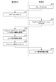
- FIG. 10 is a flowchart showing an example of multi-link processing in the wireless system according to the embodiment.
- FIG. 11 is a conceptual diagram showing an example of a beacon signal output method in a base station included in the wireless system according to the embodiment.
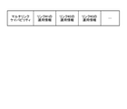
- FIG. 12 is a conceptual diagram showing an example of a beacon signal including multi-link capability information in the wireless system according to the embodiment.
- FIG. 13 is a flowchart showing an example of a data transmission method at the time of multi-link in the wireless system according to the embodiment.
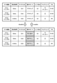
- FIG. 14 is a table showing an example of changes in link management information when the multi-link power save is applied in the wireless system according to the embodiment.
- FIG. 15 is a flowchart showing an example of the operation of the base station included in the wireless system according to the embodiment at the time of multi-link.
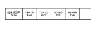
- FIG. 16 is a conceptual diagram showing an example of a beacon signal including a PVB (Partial Virtual Bitmap) in the wireless system according to the embodiment.
- FIG. 17 is a flowchart showing an example of an operation at the time of multi-link power saving of the terminal provided in the wireless system according to the embodiment.
- FIG. 18 is a flowchart showing an example of the start operation of the multi-link power save in the wireless system according to the embodiment.
- FIG. 19 is a flowchart showing an example of the end operation of the multi-link power save in the wireless system according to the embodiment.
- FIG. 20 is a flowchart showing an example of a communication method at the time of multi-link power saving in the wireless system according to the embodiment.
- FIG. 21 is a flowchart showing an example of a communication method at the time of multi-link power saving in the wireless system according to the embodiment.
- FIG. 22 is a conceptual diagram showing an example of a beacon signal including a PVB (Partial Virtual Bitmap) in the wireless system according to the embodiment.
- PVB Partial Virtual Bitmap
- the wireless system 1 according to the embodiment will be described below with reference to the drawings.
- the embodiments exemplify devices and methods for embodying the technical idea of the invention.
- the drawings are schematic or conceptual. The dimensions and ratios of each drawing are not always the same as the actual ones.
- the technical idea of the present invention is not specified by the shape, structure, arrangement, etc. of the constituent elements. Further, in the following description, components having substantially the same function and configuration are designated by the same reference numerals.
- FIG. 1 shows an example of the configuration of the wireless system 1 according to the embodiment.
- the wireless system 1 includes, for example, a base station 10, a terminal 20, and a server 30.
- the base station 10 is connected to the network NW and is used as a wireless LAN access point.
- the base station 10 can wirelessly distribute the data received from the network NW to the terminal 20.
- the base station 10 may be connected to the terminal 20 by using one kind of band or a plurality of kinds of bands.
- the wireless connection between the base station 10 and the terminal 20 using a plurality of types of bands is referred to as "multi-link".
- the communication between the base station 10 and the terminal 20 is based on, for example, the 802.11 standard.
- the terminal 20 is a wireless terminal such as a smartphone or a tablet PC.
- the terminal 20 can send and receive data to and from the server 30 on the network NW via the base station 10 wirelessly connected.
- the terminal 20 may be another electronic device such as a desktop computer or a laptop computer.
- the terminal 20 may be any device that can communicate with at least the base station 10 and can execute the operation described later.
- the server 30 can hold various information, for example, holds content data for the terminal 20.
- the server 30 is connected to, for example, a network NW by wire, and is configured to be able to communicate with the base station 10 via the network NW.
- the server 30 may be capable of communicating with at least the base station 10. That is, the communication between the base station 10 and the server 30 may be wired or wireless.
- the data communication between the base station 10 and the terminal 20 is based on the OSI (Open Systems Interconnection) reference model.
- OSI Open Systems Interconnection
- the communication function has 7 layers (1st layer: physical layer, 2nd layer: data link layer, 3rd layer: network layer, 4th layer: transport layer, 5th layer: session layer, 6th layer. Layer: presentation layer, 7th layer: application layer).
- the data link layer includes, for example, an LLC (Logical Link Control) layer and a MAC (Media Access Control) layer.
- the LLC layer forms an LLC packet by adding a DSAP (Destination Service Access Point) header, a SSAP (Source Service Access Point) header, or the like to data input from, for example, a higher-level application.
- the MAC layer adds a MAC header to, for example, an LLC packet to form a MAC frame.
- FIG. 2 shows an example of a frequency band used for wireless communication in the wireless system 1 according to the embodiment.
- a 2.4 GHz band, a 5 GHz band, and a 6 GHz band are used in wireless communication.
- Each frequency band contains a plurality of channels.
- each of the 2.4 GHz band, 5 GHz band, and 6 GHz band contains at least three channels CH1, CH2, and CH3. Communication using each channel CH is realized by the STA function described later.
- the wireless system 1 may use a frequency band other than the 2.4 GHz band, 5 GHz band, and 6 GHz band for wireless communication. At least one channel CH may be set in each frequency band. The channel CH of the same frequency band may be used for the multi-link, or the channel CH of different frequency bands may be used.
- FIG. 3 shows a specific example of the format of the wireless frame used in the communication between the base station 10 and the terminal 20 in the wireless system 1 according to the embodiment.
- the radio frame includes, for example, a Frame Control field, a Duration field, an Address1 field, an Address2 field, an Address3 field, a Sequence Control field, other control information fields, a Frame Body field, and an FCS (Frame Check Sequence) field. Includes.
- the Frame Control field to other control information fields correspond to, for example, the MAC header included in the MAC frame.
- the FrameBody field corresponds to, for example, the MAC payload contained in the MAC frame.
- the FCS field stores an error detection code between the MAC header and the Frame Body field, and is used to determine the presence or absence of an error in the radio frame.
- the Frame Control field indicates various control information, and includes, for example, a Type value, a Subtype value, a ToDS (ToDistributionSystem) value, and a FromDS value.
- the Type value indicates the frame type of the radio frame. For example, the Type value “00” indicates that the radio frame is a management frame. The Type value “01” indicates that the radio frame is a control frame. The Type value "10" indicates that the radio frame is a data frame.
- the content of the wireless frame changes depending on the combination of Type value and Subtype value. For example, "00/1000 (Type value / Subtype value)” indicates that the radio frame is a beacon signal.
- the meanings of the To DS value and From DS value differ depending on the combination. For example, “00 (To DS / From DS)” indicates that the data is between terminals in the same IBSS (Independent Basic Service Set). “10” indicates that the data frame is directed to the DS (Distribution System) from the outside. “01” indicates that the data frame goes out of the DS. “11” is used when configuring a mesh network.
- the Duration field indicates the planned period for using the wireless line.
- the plurality of Address fields indicate a BSSID, a source address, a destination address, a sender terminal address, a receiver terminal address, and the like.
- the SequenceControl field shows the sequence number of the MAC frame and the fragment number for the fragment.
- Other control information fields include, for example, traffic type (TID) information.
- TID information may be inserted at other locations within the radio frame.
- the Frame Body field contains information according to the type of frame. For example, the FrameBody field stores data when it corresponds to a data frame.
- FIG. 4 shows an example of the configuration of the base station 10 included in the wireless system 1 according to the embodiment.
- the base station 10 includes, for example, a CPU (Central Processing Unit) 11, a ROM (Read Only Memory) 12, a RAM (Random Access Memory) 13, a wireless communication module 14, and a wired communication module 15.
- a CPU Central Processing Unit
- ROM Read Only Memory
- RAM Random Access Memory
- the CPU 11 is a circuit capable of executing various programs, and controls the overall operation of the base station 10.
- the ROM 12 is a non-volatile semiconductor memory, and holds a program, control data, and the like for controlling the base station 10.
- the RAM 13 is, for example, a volatile semiconductor memory and is used as a working area of the CPU 11.
- the wireless communication module 14 is a circuit used for transmitting and receiving data by a wireless signal, and is connected to an antenna. Further, the wireless communication module 14 includes, for example, a plurality of communication modules corresponding to a plurality of frequency bands.
- the wired communication module 15 is a circuit used for transmitting and receiving data by a wired signal, and is connected to a network NW.
- FIG. 5 shows an example of the functional configuration of the base station 10 included in the wireless system 1 according to the embodiment.
- the base station 10 includes, for example, a data processing unit 110, a link management unit 120, and radio signal processing units 130, 140, and 150.
- the processing of the data processing unit 110, the link management unit 120, and the wireless signal processing units 130, 140, and 150 is realized by, for example, the CPU 11 and the wireless communication module 14.
- the data processing unit 110 can execute the processing of the LLC layer and the processing of the upper layer (third layer to the seventh layer) with respect to the input data. For example, the data processing unit 110 outputs the data input from the server 30 via the network NW to the link management unit 120. Further, the data processing unit 110 transmits the data input from the link management unit 120 to the server 30 via the network NW.
- the link management unit 120 executes, for example, a part of the processing of the MAC layer for the input data. Further, the link management unit 120 manages the link with the terminal 20 based on the notifications from the radio signal processing units 130, 140 and 150.
- the link management unit 120 includes the link management information 121.
- the link management information 121 includes, for example, information of a terminal 20 stored in a RAM 13 and wirelessly connected to the base station 10.
- the link management unit 120 includes an association processing unit 122 and an authentication processing unit 123.
- the association processing unit 122 executes the protocol related to the association when the connection request of the terminal 20 is received via any of the radio signal processing units 130, 140, and 150.
- the authentication processing unit 123 executes a protocol related to authentication following the connection request.
- Each of the wireless signal processing units 130, 140 and 150 transmits and receives data between the base station 10 and the terminal 20 using wireless communication. For example, each of the wireless signal processing units 130, 140, and 150 creates a wireless frame by adding a preamble, a PHY header, or the like to the data input from the link management unit 120. Then, each of the radio signal processing units 130, 140, and 150 converts the radio frame into a radio signal and distributes the radio signal via the antenna of the base station 10. Further, each of the radio signal processing units 130, 140, and 150 converts the radio signal received via the antenna of the base station 10 into a radio frame. Then, each of the radio signal processing units 130, 140, and 150 outputs the data contained in the radio frame to the link management unit 120.
- each of the radio signal processing units 130, 140, and 150 can execute, for example, a part of the processing of the MAC layer and the processing of the first layer on the input data or the radio signal.
- the radio signal processing unit 130 handles a radio signal in the 2.4 GHz band.
- the radio signal processing unit 140 handles radio signals in the 5 GHz band.
- the radio signal processing unit 150 handles a radio signal in the 6 GHz band.
- the radio signal processing units 130, 140 and 150 may or may not share the antenna of the base station 10.
- FIG. 6 shows an example of the configuration of the terminal 20 included in the wireless system 1 according to the embodiment.
- the terminal 20 includes, for example, a CPU 21, a ROM 22, a RAM 23, a wireless communication module 24, a display 25, and a storage 26.
- the CPU 21 is a circuit capable of executing various programs, and controls the overall operation of the terminal 20.
- the ROM 22 is a non-volatile semiconductor memory, and holds a program, control data, and the like for controlling the terminal 20.
- the RAM 23 is, for example, a volatile semiconductor memory and is used as a working area of the CPU 21.
- the wireless communication module 24 is a circuit used for transmitting and receiving data by a wireless signal, and is connected to an antenna. Further, the wireless communication module 24 includes, for example, a plurality of communication modules corresponding to a plurality of frequency bands.
- the display 25 displays, for example, a GUI (Graphical User Interface) corresponding to the application software.
- the display 25 may have a function as an input interface of the terminal 20.
- the storage 26 is a non-volatile storage device, and holds, for example, the system software of the terminal 20.
- the terminal 20 does not have to be provided with a display. For example, in an IoT terminal, the display 25 may be
- FIG. 7 shows an example of the functional configuration of the terminal 20 included in the wireless system 1 according to the embodiment.
- the terminal 20 includes, for example, a data processing unit 210, a link management unit 220, a radio signal processing unit 230, 240 and 250, and an application execution unit 260.
- the processing of the data processing unit 210, the link management unit 220, and the wireless signal processing units 230, 240, and 250 is realized by, for example, the CPU 21 and the wireless communication module 24.
- the data processing unit 210 can execute the processing of the LLC layer and the processing of the upper layer (third layer to the seventh layer) with respect to the input data. For example, the data processing unit 210 outputs the data input from the application execution unit 260 to the link management unit 220. Further, the data processing unit 210 outputs the data input from the link management unit 220 to the application execution unit 260.
- the link management unit 220 executes, for example, a part of the processing of the MAC layer for the input data. Further, the link management unit 220 manages the link with the base station 10 based on the notifications from the radio signal processing units 230, 240 and 250.
- the link management unit 220 includes the link management information 221.
- the link management information 221 contains, for example, information about a base station 10 stored in a RAM 23 and wirelessly connected to the terminal 20.
- the link management unit 220 includes an association processing unit 222 and an authentication processing unit 223.
- the association processing unit 222 executes the protocol related to the association when the connection request of the base station 10 is received via any of the radio signal processing units 230, 240, and 250.
- the authentication processing unit 223 executes a protocol related to authentication following the connection request.
- Each of the wireless signal processing units 230, 240, and 250 transmits and receives data between the base station 10 and the terminal 20 using wireless communication.
- each of the wireless signal processing units 230, 240, and 250 creates a wireless frame by adding a preamble, a PHY header, or the like to the data input from the link management unit 220.
- each of the radio signal processing units 230, 240, and 250 converts the radio frame into a radio signal and distributes the radio signal via the antenna of the terminal 20.
- each of the wireless signal processing units 230, 240, and 250 converts the wireless signal received via the antenna of the terminal 20 into a wireless frame.
- each of the radio signal processing units 230, 240, and 250 outputs the data contained in the radio frame to the link management unit 220.
- each of the radio signal processing units 230, 240, and 250 can execute, for example, a part of the processing of the MAC layer and the processing of the first layer on the input data or the radio signal.
- the radio signal processing unit 230 handles a radio signal in the 2.4 GHz band.
- the radio signal processing unit 240 handles radio signals in the 5 GHz band.
- the radio signal processing unit 250 handles a radio signal in the 6 GHz band.
- the wireless signal processing units 230, 240 and 250 may or may not share the antenna of the terminal 20.
- the application execution unit 260 executes an application that can use the data input from the data processing unit 210. For example, the application execution unit 260 can display the information of the application on the display 25. Further, the application execution unit 260 may operate based on the operation of the input interface.
- the wireless signal processing units 130, 140 and 150 of the base station 10 are configured to be connectable to the wireless signal processing units 230, 240 and 250 of the terminal 20, respectively. That is, the wireless signal processing units 130 and 230 can be wirelessly connected using the 2.4 GHz band.
- the wireless signal processing units 140 and 240 may be wirelessly connected using the 5 GHz band.
- the wireless signal processing units 150 and 250 may be wirelessly connected using the 6 GHz band.
- each radio signal processing unit may be referred to as a “STA function”. That is, the wireless system 1 according to the embodiment has a plurality of STA functions.
- FIG. 8 shows the details of the channel access function in the link management unit 120 of the base station 10 included in the wireless system 1 according to the embodiment. Since the function of the link management unit 220 of the terminal 20 is the same as that of the link management unit 120 of the base station 10, for example, the description thereof will be omitted.
- the link management unit 120 includes, for example, a data categorization unit 124, transmission queues 125A, 125B, 125C, 125D and 125E, and a CSMA / CA (Carrier Sense Multiple Access with Collision Avoidance) execution unit 126A, 126B, 126C. , 126D and 126E, and a data collision management unit 127.
- a data categorization unit 124 transmission queues 125A, 125B, 125C, 125D and 125E
- CSMA / CA Carrier Sense Multiple Access with Collision Avoidance
- the data categorization unit 124 categorizes the data input from the data processing unit 110.
- As the data category for example, "LL (Low Latency)”, “VO (Voice)”, “VI (Video)”, “BE (Best Effort)”, and “BK (Background)” are set. LL is applied to data that requires low delay. Therefore, it is preferable that the LL data is processed in preference to any of the VO, VI, BE and BK data.
- the data categorization unit 124 inputs the categorized data to any of the transmission queues 125A, 125B, 125C, 125D and 125E.
- the LL data is input to the transmission queue 125A.
- the VO data is input to the transmission queue 125B.
- the VI data is input to the transmission queue 125C.
- BE data is input to the transmission queue 125D.
- the BK data is input to the transmission queue 125E.
- the input data of each category is accumulated in any of the corresponding transmission queues 125A to E.
- Each of the CSMA / CA execution units 126A, 126B, 126C, 126D and 126E uses preset access parameters while confirming that the carrier sense does not transmit radio signals from other terminals or the like in the CSMA / CA. Wait for transmission for the specified time. Then, the CSMA / CA execution units 126A, 126B, 126C, 126D and 126E extract data from the transmission queues 125A, 125B, 125C, 125D and 125E, respectively, and process the extracted data via the data collision management unit 127. Output to at least one of units 130, 140 and 150. Then, the radio signal including the data is transmitted by the radio signal processing unit (STA function) whose transmission right has been acquired by CSMA / CA.
- STA function radio signal processing unit
- the CSMA / CA execution unit 126A executes CSMA / CA for the LL data held in the transmission queue 125A.
- the CSMA / CA execution unit 126B executes CSMA / CA for the VO data held in the transmission queue 125B.
- the CSMA / CA execution unit 126C executes CSMA / CA for the VI data held in the transmission queue 125C.
- the CSMA / CA execution unit 126D executes CSMA / CA for the BE data held in the transmission queue 125D.
- the CSMA / CA execution unit 126E executes CSMA / CA for the BK data held in the transmission queue 125E.
- Access parameters are assigned so that the transmission of radio signals is prioritized in the order of, for example, LL, VO, VI, BE, and BK.
- Access parameters include, for example, CWmin, CWmax, AIFS, TXOPLimit.
- CWmin and CWmax indicate the minimum value and the maximum value of the contention window, which is the transmission waiting time for collision avoidance, respectively.
- AIFS Aribitration InterFrame Space
- TXOPLimit indicates an upper limit value of TXOP (Transmission Opportunity) corresponding to the occupation time of the channel.
- the priority of the transmission queue 125 becomes higher as the AIFS is smaller.
- the amount of data transmitted with one transmission right increases as the value of TXOP Limit increases.
- the data collision management unit 127 prevents data collisions when a plurality of CSMA / CA execution units 126 acquire transmission rights with the same STA function. Specifically, the data collision management unit 127 adjusts the transmission timing of the data in which the transmission right is acquired by the same STA function in different categories, and transmits the data in the high priority category to the STA function.
- the STA function acquired by the CSMA / CA of the transmission queue 125A of the LL may be the same as the STA function acquired the transmission right by the CSMA / CA of any of the other transmission queues 125B to 125E. ..
- the data collision management unit 127 gives priority to the data stored in the transmission queue 125A and transmits the data to the STA function.
- the data is transmitted in the order based on the priority set in the category. This prevents collisions between data to which transmission is assigned to the same STA function.
- each STA function may implement the channel access function.
- each STA function detects the state (idle / busy) of the radio channel in the corresponding link, and the link management unit determines whether or not data can be transmitted (which link). Send using, etc.).
- each STA function may independently execute carrier sense and transmit data.
- the channel access when a plurality of links are used at the same time may be executed by standardizing the access parameters by exchanging between the plurality of STA functions, and the access parameters are standardized by the link management unit. It may be executed by.
- the base station 10 and the terminal 20 can use a plurality of links at the same time by transmitting data among the plurality of STA functions based on common access parameters.
- FIG. 9 shows an example of the link management information 121 in the wireless system 1 according to the embodiment. Since the link management information 221 of the terminal 20 has information similar to the link management information 121 of the base station 10, the description thereof will be omitted. As shown in FIG. 9, the link management information 121 includes information on each of, for example, the STA function, the frequency band, the channel ID, the link destination ID, the multilink, and the TID.
- STA1 corresponds to the STA function using the frequency band of 6 GHz, that is, the radio signal processing unit 150 or 250.
- STA2 corresponds to the STA function using the frequency band of 5 GHz, that is, the radio signal processing unit 140 or 240.
- STA3 corresponds to the STA function using the frequency band of 2.4 GHz, that is, the radio signal processing unit 130 or 230.
- STA1, STA2, and STA3 are also referred to as link # 1, link # 2, and link # 3, respectively.
- the channel ID corresponds to the identifier of the channel used in the set frequency band.
- the link destination ID corresponds to the identifier of the terminal 20 in the link management information 121, and corresponds to the identifier of the base station 10 in the link management information 221.
- a multi-link using STA1, STA2 and STA3 has been established.
- each of the link management units 120 and 220 transmits the data input from the upper layer using the link of at least one STA function associated with the multi-link.
- the base station 10 sets one STA function among a plurality of STA functions as an anchor link.
- STA1 is set as the anchor link.
- the anchor link is set by the link management unit 120 of the base station 10.
- the anchor link sends and receives control information related to the operation of the multi-link. It should be noted that the combination of links constituting the multi-link may be different between the base station 10 and the plurality of terminals 20 each of which has established the multi-link.
- TID in the link management information 121 indicates the association between the STA function and the TID information.
- Each STA function sends and receives data corresponding to the assigned TID information.
- TIDs # 1 to 4 corresponds to any one of LL, VO, VI, BE, and BK.
- One STA function may be associated with one traffic, that is, one TID information, or a plurality of STA functions may be associated with each other.
- TID # 1 is assigned to both STA1 and STA2.
- TID # 2 is assigned to STA1.
- TID # 3 is assigned to STA2.
- TID # 4 is assigned to STA3.
- the traffic flow corresponding to the association between the traffic and the STA function is preset at the time of setting up the multi-link between the base station 10 and the terminal 20.
- the link management unit 220 of the terminal 20 determines the correspondence between the traffic and the STA function, and requests the link management unit 120 of the base station 10. Then, when the base station 10 responds to the request, the association between the traffic and the STA function is confirmed.
- the traffic is set to be even among a plurality of links constituting the multi-link, for example.
- similar types of traffic may be collected in one of the links constituting the multilink.
- audio is associated with a frequency band of 2.4 GHz
- video is associated with 5 G.
- the frequency used for transmission / reception is assigned according to the type of information to be handled and the amount of data.
- FIG. 10 shows an example of the flow of multi-link processing in the wireless system 1 according to the embodiment.
- the processes of steps S10 to S16 are executed in order.
- the processing of steps S10 to S16 will be described by exemplifying a case where a multi-link using three STA functions is formed.
- the terminal 20 transmits a probe request to the base station 10.
- the probe request is a signal for confirming whether or not the base station 10 exists in the vicinity of the terminal 20.
- the Frame Control field of the probe request contains, for example, "00/0100 (Type value / Subtype value)".
- the base station 10 executes the process of step S11.
- the base station 10 transmits a probe response to the terminal 20.
- the probe response is a signal used by the base station 10 to respond to a probe request from the terminal 20.
- the Frame Control field of the probe response contains, for example, "00/0101 (Type value / Subtype value)".
- the terminal 20 executes the process of step S12.
- the terminal 20 transmits a multi-link association request to the base station 10 via at least one STA function.
- the multi-link association request is a signal for requesting the base station 10 to establish a multi-link.
- the multi-link association request is generated by the link management unit 220 of the terminal 20.
- the Frame Control field of the multi-link association request contains, for example, "00 / xxxx (Type value / Subtype value (xxxx is a predetermined numerical value))".
- the link management unit 120 of the base station 10 executes the process of step S13.
- the link management unit 120 of the base station 10 executes the multi-link association process using one STA function. Specifically, first, the base station 10 executes the association processing of the first STA function with the terminal 20. Then, when the wireless connection (link) is established in the first STA function, the link management unit 120 of the base station 10 uses the first STA function in which the link is established to use the second STA function. The association processing of the STA function and the association processing of the third STA function are executed. That is, the STA function with an established link is used for the association processing of the STA function with no established link. When the association processing of at least two STA functions is completed, the base station 10 establishes the multi-link and executes the processing of step S14.
- step S14 the link management unit 120 of the base station 10 updates the link management information 121.
- the process of step S14 is executed after the two links are established, but the link management information 121 may be updated every time the link state is updated, or the multi-link is established. It may be updated at the time.
- the base station 10 executes the process of step S15.
- the base station 10 transmits a multi-link establishment response to the terminal 20.
- the multi-link establishment response is a signal used by the base station 10 to respond to a multi-link request from the terminal 20.
- the Frame Control field of the multi-link association request contains, for example, "00/0001 (Type value / Subtype value)".
- the link management unit 220 of the terminal 20 recognizes that the multi-link with the base station 10 has been established based on the reception of the multi-link establishment response.
- the terminal 20 executes the process of step S16.
- step S16 the link management unit 220 of the terminal 20 updates the link management information 221. That is, the terminal 20 records in the link management information 221 that the multi-link with the base station 10 has been established. As a result, the multi-link processing in the wireless system 1 according to the embodiment is completed, and data communication using the multi-link becomes possible between the base station 10 and the terminal 20.
- the wireless system 1 may establish a multi-link when establishing a link in the first STA function.
- the terminal 20 receives the beacon signal related to the multilink from the base station 10 before the multilink association request in step S12.
- this operation will be described with reference to FIGS. 11 and 12.
- FIG. 11 shows an example of a beacon signal output method in the base station 10 included in the wireless system 1 according to the embodiment.
- the link # 1 of the links # 1 to # 3 is set as the anchor link.
- the base station 10 intermittently transmits the beacon signal by using the link # 1 set as the anchor link.
- transmission of the beacon signal by links # 2 and # 3 that are not set as anchor links is omitted.
- the beacon signal may be transmitted using a link that is not set as an anchor link, or at least may be transmitted using an anchor link.
- FIG. 12 shows a specific example of a beacon signal including multi-link capability information in the wireless system 1 according to the embodiment.
- the beacon signal includes, for example, multi-link capability information, operation information of link # 1, operation information of link # 2, and operation information of link # 3. This information is generated by the link management unit 120 of the base station 10.
- the multi-link capability information indicates whether or not the base station 10 can be multi-linked. For example, when the multi-link capability information is "0", it indicates that multi-link is impossible. When the multi-link capability information is "1", it indicates that multi-link is possible.
- the link operation information indicates a parameter for performing data transmission or the like in a link that can be used in a multi-link. For example, the operation information of the link # 1 indicates an access parameter of EDCA (Enhanced Distributed Channel Access) for performing transmission control in the link.
- EDCA Enhanced Distributed Channel Access
- the terminal 20 When the terminal 20 receives the beacon signal described with reference to FIG. 12, the terminal 20 confirms the multi-link capability information and the operation information of each link that is the target of the multi-link from the beacon signal. Then, the link management unit 220 of the terminal 20 notifies the link management unit 120 of the base station 10 of information such as a link to be the target of the multi-link at the time of the multi-link association request. As a result, the link management unit 120 of the base station 10 can collectively execute the association of a plurality of links designated by the link management unit 220 of the terminal 20 and establish a multi-link with the terminal 20.
- the beacon signal When the above-mentioned beacon signal is transmitted only by the anchor link, the beacon signal does not have to have a field indicating the anchor link. On the other hand, when the beacon signal is transmitted on an anchor link and other links, the beacon signal may have a field indicating an anchor link and a field indicating another link. Further, the base station 10 may add the information contained in the above-mentioned beacon signal to the probe response. In this case, the link management unit 220 of the terminal 20 can transmit the multi-link association request specifying the link to be used to the base station 10 without receiving the beacon signal. Further, the base station 10 and the terminal 20 may execute an authentication process when establishing the multi-link.
- FIG. 13 shows an example of a method of transmitting data at the time of multi-link in the base station 10 included in the wireless system 1 according to the embodiment.
- the base station 10 when the base station 10 acquires data from the upper layer, the base station 10 sequentially executes the processes of steps S20 to S22. The processing of steps S20 to S22 will be described below.
- the link management unit 120 acquires the TID information corresponding to the data.
- the link management unit 120 associates the data with the TID by referring to the control information such as the header added to the data acquired from the upper layer, for example.
- the link management unit 120 acquires the STA function corresponding to the confirmed TID information. At this time, the link management unit 120 confirms the association between the TID information and the STA function by referring to the link management information 121. In the process of step S21, the number of STA functions acquired by the link management unit 120 may be one or a plurality.
- the link management unit 120 outputs data to the acquired STA function.
- one STA function is associated with the output data (traffic)
- the data is transmitted serially using one STA function.
- the data is transmitted in parallel using the plurality of STA functions.
- data distribution and sorting are executed between the link management unit 120 of the base station 10 and the link management unit 220 of the terminal 20.
- the data distribution is executed by the link management unit on the transmitting side
- the sorting of the data is executed by the link management unit on the receiving side.
- the link management unit on the transmitting side adds a flag indicating that the radio frame is multi-link and an identification number to the wireless frame.
- the link management unit on the receiving side executes data sorting based on the added flag and the identification number.
- the link management unit may execute aggregation by combining the received plurality of data. Aggregation in multilink may be used as an optional feature that can be selected by the user.
- a plurality of types of operation modes are prepared for each STA function.
- Examples of the operation mode of the STA function include an active mode, an intermittent operation mode, and an operation pause mode.
- the active mode corresponds to a state in which the STA function of the terminal 20 maintains the Awake state so that wireless signals can be transmitted and received at any time.
- the intermittent operation mode corresponds to a state in which the STA function of the terminal 20 repeats the Awake state and the Doze state to operate intermittently.
- the operation hibernation mode corresponds to a state in which transmission / reception of wireless signals is impossible by maintaining the Doze state of the STA function of the terminal 20.
- the "Awake state” corresponds to a state in which wireless signals can be transmitted and received.
- the Dose state corresponds to the state in which wireless signals cannot be transmitted or received.
- the "Doze state” the supply of power to the circuit related to the STA function is appropriately cut off. Therefore, the power consumption of the STA function decreases in the order of active mode, intermittent operation mode, and operation pause mode.
- the base station 10 or the terminal 20 can be used for communication, there may be a link between them that is not included in the multi-link link set (Disabled link).
- a link in active mode or intermittent operation mode that is, a link that can communicate is referred to as an “STA function (link) in the Awake state”.
- the link in the operation hibernation mode that is, the link in the power saving state in which communication is impossible, is called the "STA function (link) in the Dose state”.
- the anchor link is set to, for example, either an active mode or an intermittent operation mode.
- the links other than the anchor links are set to any of the active mode, the intermittent operation mode, and the operation pause mode.
- the terminal 20 can operate in a power saving manner by setting a link other than the anchor link to the operation hibernation mode at the time of multilink.
- multi-link power save the state of the multi-link in which the anchor link is set to the intermittent operation mode and the links other than the anchor link are set to the operation hibernation mode.
- FIG. 14 shows an example of a change in the link management information 121 when the multi-link power save is applied in the wireless system 1 according to the embodiment.
- the upper and lower tables of FIG. 14 correspond to when the multi-link power save is not applied and when it is applied, respectively.
- the link management information 121 further includes information on the operation mode.
- each operation mode of STA1, STA2 and STA3 is set to the active mode.
- Other parameters of the link management information 121 when the multi-link power save is not applied in this example are the same as those of the link management information 121 shown in FIG.
- the operation modes of STA1, STA2 and STA3 are set to the intermittent operation mode, the operation pause mode, and the operation pause mode, respectively.
- the other parameters of the link management information 121 when the multi-link power save is applied are the same as when the multi-link power save is not applied.
- Multi-link power save on / off is applied by the Doze transition notification signal (“disable”) and the Awake transition request signal (“enable”), respectively.
- the terminal 20 transmits a Doze transition notification signal to the base station 10 after the multi-link is set, the terminal 20 is set to the multi-link power save.
- the base station 10 transmits an Awake transition request signal to the terminal 20 while the terminal 20 is set to the multi-link power save, the setting of the multi-link power save of the terminal 20 is canceled.
- the Awake transition request signal and the Doze transition notification signal may be transmitted from either the base station 10 or the terminal 20.
- the transmission of the Awake transition request signal is performed using an anchor link or other activated link.
- the transmission of the Doze transition notification signal is executed using an anchor link or a link that stops (a link that shifts to the hibernation mode).
- the multi-link power save may be applied when the multi-link is established.
- the multi-link power save may be at least more power-saving than the case where the multi-link power save is not applied.
- the anchor link may be set to active mode and the other links may be set to hibernate mode.
- FIG. 15 shows an example of the operation of the base station 10 included in the wireless system 1 according to the embodiment at the time of multilink.
- the link management unit 120 of the base station 10 confirms the multi-link status when there is buffer data (step S30).
- the buffer data is data received by the base station 10 via the network NW, and indicates, for example, data stored in the transmission queue 125.
- the link management unit 120 of the base station 10 confirms whether or not the link associated with the buffer data is in the intermittent operation mode or the operation pause mode (step S31).
- the link management unit 120 of the base station 10 When the link associated with the buffer data is in the intermittent operation mode or the operation pause mode (step S31, YES), the link management unit 120 of the base station 10 outputs a beacon signal including a PVB (Partial Virtual Bitmap) for each TID. It is transmitted to the terminal 20 (step S32).
- the creation of the beacon signal may be executed by the link management unit 120 or may be executed by the STA function of the anchor link.
- the link management unit 120 of the base station 10 transmits the data to the destination terminal 20 (step S33).
- FIG. 16 shows a specific example of a beacon signal including PVB in the wireless system 1 according to the embodiment.
- the beacon signal includes, for example, a terminal identifier and PVBs of a plurality of TIDs.
- the terminal identifier includes, for example, an association identifier AID (Association Identifier) between the base station 10 and the terminal 20.
- the PVB of a plurality of TIDs includes, for example, PVB of TID # 1, PVB of TID # 2, PVB of TID # 3, and PVB of TID # 4. For example, when the PVB of TID # 1 is "0", it indicates that the traffic of TID # 1 is not accumulated. When the PVB of TID # 1 is "1", it indicates that the traffic of TID # 1 is accumulated.
- the combination of the bits assigned to the PVB and the presence or absence of traffic accumulation can be arbitrarily changed. Further, the number of PVBs of a plurality of TIDs included in the beacon signal can be changed based on the set number of TIDs.
- FIG. 17 shows an example of the operation of the terminal 20 included in the wireless system 1 according to the embodiment at the time of multi-link power saving.
- the anchor link of the terminal 20 in the intermittent operation mode receives the beacon signal (step S40).
- the link management unit 220 of the terminal 20 confirms the AID included in the beacon signal and the PVB of each TID, and confirms whether or not there is buffer data addressed to its own station (step S41).
- step S41, NO If there is no buffer data addressed to the own station (step S41, NO), the terminal 20 ends this operation.
- the link management unit 220 of the terminal 20 indicates whether or not the link associated with the buffer data is in the Awake state, that is, in the active mode or the intermittent operation mode. It is confirmed whether or not (step S42).
- the link management unit 220 of the terminal 20 requests the base station 10 to transmit the data (step S43).
- the link management unit 220 of the terminal 20 first wakes up the link associated with the buffer data, that is, transitions from the Doze state to the Awake state. .. After that, the link management unit 220 of the terminal 20 requests the base station 10 to transmit data (step S43).
- the terminal 20 executes the operation described above every time the anchor link receives the beacon signal.
- the link management unit 220 of the terminal 20 transitions the link to the Doze state again.
- the timing at which the link management unit 220 of the terminal 20 transitions the wake-up link to the Doze state can be set to any timing.
- the timing at which the link management unit 220 of the terminal 20 transitions the wake-up link to the Doze state may be the timing when the buffer data addressed to the link disappears, or the buffer data addressed to the link disappears. It may be the timing when a predetermined time has elapsed from.
- FIG. 18 shows an example of the flow of the start operation of the multi-link power save in the wireless system 1 according to the embodiment.
- each of STA1, STA2 and STA3 is in the active state.
- the access point AP transmits a beacon signal to the STA1 of the terminal 20, that is, the anchor link (step S50).
- This beacon signal contains information indicating that the traffic of each of STA1, STA2 and STA3 is empty, for example.
- the STA1 of the terminal 20 transmits a radio signal notifying the start of the multi-link power save to the access point AP, for example, in response to an empty traffic (step S51).
- the data frame (DataFrame) of the radio signal notifying the start of the multi-link power save includes, for example, a PM (Power Management) bit in which "1" is stored.
- the terminal 20 in the wireless system 1 shifts to the multi-link power save according to the traffic state, and suppresses the power consumption of the multi-link. Then, based on the transition of the terminal 20 to the multi-link power save, the base station 10 intermittently transmits a beacon signal including a PVB for notifying the data buffer status by using the anchor link in the Awake state. Send.
- a beacon signal including a PVB for notifying the data buffer status by using the anchor link in the Awake state.
- Send The details of the communication method between the base station 10 and the terminal 20 during the multi-link power save will be described later.
- FIG. 19 shows an example of the flow of the end operation of the multi-link power save in the wireless system 1 according to the embodiment.
- STA1 is in the Awake state
- STA2 and STA3 are in the Doze state.
- the access point AP transmits a beacon signal to the STA1 of the terminal 20, that is, the anchor link (step S60).
- This beacon signal contains, for example, information requesting the terminal 20 to end the multi-link power save.
- the STA1 of the terminal 20 transmits a wireless signal notifying the end of the multi-link power save to the access point AP in response to receiving the beacon signal (step S61).
- the data frame of the radio signal notifying the end of the multi-link power save includes, for example, a PM bit containing "0".
- the link management unit 220 of the terminal 20 shifts the STA1 from the intermittent operation mode (Awake state) to the active mode. , STA2 and STA3 are transitioned from the operation pause mode (Doze state) to the active mode (step S53). As a result, each of STA1, STA2, and STA3 constituting the multi-link becomes ready to receive the radio signal from the base station 10.
- This beacon signal contains various information elements necessary for communication.
- the base station 10 in the wireless system 1 shifts the STA function set in the intermittent operation mode or the operation pause mode to the active mode in the multilink to form the multilink.
- Multiple STA functions can be set to be communicable.
- the link management unit 220 of the terminal 20 may notify the link management unit 120 of the base station 10 of the end of the multi-link power save based on the user's operation or the control of the application.
- FIG. 20 corresponds to the operation when the access point AP receives the data of TID # 2.
- FIG. 21 corresponds to the operation when the access point AP receives the data of TID # 3.
- the TID assigned to each link in this example is the same as the link management information 121 described with reference to FIG.
- the operation when the access point AP receives the data of TID # 2 assigned to STA1 (anchor link) during the multi-link power save will be described.
- the access point AP receives the data of TID # 2 from the network NW, for example, the data is stored in the transmission queue 125 of the link management unit 120. Then, the access point AP transmits a beacon signal including PVB indicating that the buffer status of the data of TID # 2 is “1” to STA1 (step S70).
- the link management unit 220 refers to the beacon signal and confirms the presence or absence of buffer data for each TID.
- the link management unit 220 confirms that the data of TID # 2 is buffered and that the STA1 associated with the data of TID # 2 is in the Awake state. Based on this confirmation result, the link management unit 220 transmits a PS-Poll (PowerSave-Poll) frame requesting data transmission to the access point AP via STA1 (step S71).
- PS-Poll PowerSave-Poll
- the access point AP When the access point AP receives the PS-Poll frame from the STA1 of the terminal 20, it transmits a DataACK including the data of the TID # 2 to the STA1 of the terminal 20 (step S72). As a result, the STA1 of the terminal 20 can receive the data for its own station stored in the access point AP.
- the access point AP When the transmission of the data of TID # 2 is completed and the accumulation of the data of TID # 2 in the transmission queue 125 is canceled, the access point AP indicates that the buffer status of the data of TID # 2 is "0". A beacon signal including PVB is transmitted to STA1 of the terminal 20 (step S73). That is, the access point AP notifies the link management unit 220 of the terminal 20 via the STA 1 that the transmission of the data of the TID # 2 is completed.
- the access point AP receives the data of TID # 3 assigned to STA2 during the multi-link power save.
- the access point AP receives the data of TID # 3 from the network NW, for example, the data is stored in the transmission queue 125 of the link management unit 120. Then, the access point AP transmits a beacon signal including PVB indicating that the buffer status of the data of TID # 3 is “1” to STA1 (step S80).
- the beacon signal received by the STA1 of the terminal 20 is transferred to the link management unit 220.
- the link management unit 220 refers to the beacon signal and confirms the presence or absence of buffer data for each TID.
- the link management unit 220 confirms that the data of TID # 3 is buffered and that the STA2 to which the data of TID # 3 is associated is in the Doze state. Based on this confirmation result, the link management unit 220 wakes up the STA2, that is, transitions from the Doze state to the Awake state (step S81).
- the link management unit 220 transmits a PS-Poll (Power Save-Poll) frame requesting transmission of TID # 3 data to the access point AP via STA2 (step S82).
- PS-Poll Power Save-Poll
- the access point AP receives the PS-Poll frame from the STA2 of the terminal 20, it transmits a Data ACK including the data of TID # 3 to the STA2 of the terminal 20 (step S83).
- the STA2 of the terminal 20 can receive the data for its own station stored in the access point AP.
- the access point AP When the transmission of the data of TID # 3 is completed and the accumulation of the data of TID # 3 in the transmission queue 125 is canceled, the access point AP indicates that the buffer status of the data of TID # 3 is "0".
- a beacon signal including PVB is transmitted to STA1 of the terminal 20 (step S84). That is, the access point AP notifies the link management unit 220 of the terminal 20 via the STA 1 that the transmission of the data of the TID # 3 is completed. This beacon signal may be received by the STA2.
- the link management unit 220 shifts the STA2 from the Awake state to the Doze state based on the received beacon signal (step S85). That is, during the multi-link power save, the links other than the anchor links among the plurality of links constituting the multi-link are set to the Doze state again based on the completion of data transmission.
- the base station 10 in the wireless system 1 can transmit data to the terminal 20 using the multi-link power save.
- the case where the base station 10 receives the data of the TID assigned to the STA 2 during the multi-link power save has been described, but the present invention is not limited to this.
- STA3 can wake up from the Doze state and receive data.
- data may be transmitted in parallel to each of a plurality of STA functions constituting the multi-link.
- the link management unit 220 of the terminal 20 may instruct each of STA1 and STA2 to transmit the PS-Poll frame to the access point AP. good.
- the link management unit 220 of the terminal 20 can wake up the plurality of links. That is, the link management unit 220 of the terminal 20 can wake up the links in the Doze state and receive the data according to the data buffer status, regardless of the number of links constituting the multi-link.
- FIG. 22 shows an example of a beacon signal transmitted from the access point AP in this example.
- the PVB of TID # 1 may include the PVB of link # 1 associated with TID # 1 and the PVB of link # 2 associated with TID # 1.
- Base stations and terminals that use wireless LAN may have a plurality of STA functions provided for each band used, for example, 2.4 GHz, 5 GHz, and 6 GHz.
- a wireless connection is established by selecting one STA function from a plurality of STA functions, and data communication between a base station and a terminal is performed.
- the unselected STA function is not used even if there is a base station corresponding to the band of the STA function.
- the wireless system 1 utilizes a plurality of STA functions provided in each of the base station 10 and the terminal 20 to establish a multi-link between the base station 10 and the terminal 20.
- a plurality of bands can be used together, and the functions of the wireless LAN device can be fully utilized.
- the wireless system 1 according to the embodiment can realize efficient communication and can improve the communication speed.
- the power consumption of the multi-link is higher than that of the single link because the base station 10 and the terminal 20 each use a plurality of STA functions.
- the wireless system 1 sets the multi-link to the multi-link power save when there is little traffic or the like.
- the multi-link power save for example, at least one STA function among a plurality of STA functions constituting the multi-link is set to the normal state (Awake state), and the other STA functions are set to the power saving state (Doze state).
- the STA function in the Awake state can receive, for example, the beacon signal of the base station 10. Further, the STA function in the Doze state is stopped as in the Disable state, for example. Therefore, the power consumption of the STA function in the Doze state is lower than that of the STA function in the Awake state.
- the STA function in the Awake state receives a beacon signal including information corresponding to a plurality of STA functions constituting the multi-link.
- the base station 10 informs the terminal 20 that the data is accumulated via the STA function (link) in the Awake state. Notice.
- the STA function of the terminal 20 transfers the notification to the link management unit 220, and the link management unit 220 wakes up the STA function in the Doze state.
- the wake-up STA function can acquire data from the base station 10 by transmitting a PS-Poll frame.
- the wireless system 1 can suppress the power consumption of the terminal 20 by utilizing the multi-link power save. Then, the link management unit 220 of the terminal 20 can appropriately wake up the STA function in the Doze state based on the beacon signal received by the STA function in the Awake state at the time of multi-link power save. Thereby, data communication between the base station 10 and the terminal 20 can be realized even at the time of multi-link power saving. As a result, the wireless system 1 according to the embodiment can suppress the delay in latency at the time of multi-link power saving.
- each STA function may notify the corresponding link management unit when the link cannot be maintained due to the movement of the terminal 20 or the like.
- the link management unit 220 of the terminal 20 may change the multi-link state with the link management unit 120 of the base station 10 based on the notification from the STA function. Specifically, for example, the link management unit 220 of the terminal 20 and the link management unit 120 of the base station 10 may appropriately change the STA function used in the multi-link.
- the link management units 120 and 220 update the link management information 121 and 221, respectively. Further, the link management units 120 and 220 may update the association between the traffic and the STA function according to the increase or decrease in the number of links.
- the configuration of the wireless system 1 according to the embodiment is only an example, and other configurations may be used.
- the base station 10 may include at least two radio signal processing units.
- the terminal 20 may include at least two radio signal processing units.
- the number of channels that can be processed by each STA function can be appropriately set according to the frequency band used.
- Each of the wireless communication modules 14 and 24 may support wireless communication in a plurality of frequency bands by a plurality of communication modules, or may support wireless communication in a plurality of frequency bands by one communication module.
- the functional configurations of the base station 10 and the terminal 20 in the wireless system 1 are merely examples.
- the functional configurations of the base station 10 and the terminal 20 may have other names and groups as long as they can perform the operations described in each embodiment.
- the data processing unit 110 and the link management unit 120 may be collectively referred to as a data processing unit.
- the data processing unit 210 and the link management unit 220 may be collectively referred to as a data processing unit.
- the CPU included in each of the base station 10 and the terminal 20 may be another circuit.
- MPU Micro Processing Unit
- each of the processes described in each embodiment may be realized by dedicated hardware.
- the wireless system 1 according to each embodiment may have a mixture of processes executed by software and processes executed by hardware, or may be only one of them.
- the flowchart used to explain the operation is just an example. Each operation described in the embodiment may be interchanged within the range in which the order of processing is possible, or other processing may be added. Further, the format of the wireless frame described in the above embodiment is merely an example. The radio system 1 may use other radio frame formats as long as it is possible to perform the operations described in each embodiment.
- the present invention is not limited to the above embodiment, and can be variously modified at the implementation stage without departing from the gist thereof.
- each embodiment may be carried out in combination as appropriate, in which case the combined effect can be obtained.
- the above-described embodiment includes various inventions, and various inventions can be extracted by a combination selected from a plurality of disclosed constituent requirements. For example, even if some constituent elements are deleted from all the constituent elements shown in the embodiment, if the problem can be solved and the effect is obtained, the configuration in which the constituent elements are deleted can be extracted as an invention.
- Wireless system 10 ... Base station 20 ... Terminal 30 ... Servers 11 and 21 ... CPU 12, 22 ... ROM 13, 23 ... RAM 14, 24 ... Wireless communication module 15 ... Wired communication module 25 ... Display 26 ... Storage 110, 210 ... Data processing unit 120, 220 ... Link management unit 121,221 ... Link management information 122, 222 ... Association processing unit 123, 223 ... Authentication processing unit 124 ... Data categorization unit 125 ... Transmission queue 126 ... CSMA / CA execution unit 127 ... Data collision management unit 130, 140, 150, 230, 240, 250 ... Wireless signal processing unit
Landscapes
- Engineering & Computer Science (AREA)
- Computer Networks & Wireless Communication (AREA)
- Signal Processing (AREA)
- Mobile Radio Communication Systems (AREA)
Abstract
Description
<1-1>無線システム1の全体構成
図1は、実施形態に係る無線システム1の構成の一例を示している。図1に示すように、無線システム1は、例えば基地局10、端末20、及びサーバ30を備えている。
図2は、実施形態に係る無線システム1における無線通信に使用される周波数帯の一例を示している。図2に示すように、無線通信では、例えば2.4GHz帯、5GHz帯、6GHz帯が使用される。そして、各周波数帯は、それぞれ複数のチャネルを含んでいる。本例では、2.4GHz帯、5GHz帯、6GHz帯のそれぞれが、少なくとも3つのチャネルCH1、CH2及びCH3を含んでいる。各チャネルCHを用いた通信は、後述されるSTA機能によって実現される。
図3は、実施形態に係る無線システム1において、基地局10及び端末20間の通信で使用される無線フレームのフォーマットの具体例を示している。図3に示すように、無線フレームは、例えばFrame Controlフィールド、Durationフィールド、Address1フィールド、Address2フィールド、Address3フィールド、Sequence Controlフィールド、その他の制御情報フィールド、Frame Bodyフィールド、及びFCS(Frame Check Sequence)フィールドを含んでいる。
図4は、実施形態に係る無線システム1の備える基地局10の構成の一例を示している。図4に示すように、基地局10は、例えばCPU(Central Processing Unit)11、ROM(Read Only Memory)12、RAM(Random Access Memory)13、無線通信モジュール14、及び有線通信モジュール15を備えている。
図6は、実施形態に係る無線システム1の備える端末20の構成の一例を示している。図6に示すように、端末20は、例えばCPU21、ROM22、RAM23、無線通信モジュール24、ディスプレイ25、及びストレージ26を備えている。
図8は、実施形態に係る無線システム1の備える基地局10のリンクマネジメント部120におけるチャネルアクセス機能の詳細を示している。尚、端末20のリンクマネジメント部220の機能は、例えば基地局10のリンクマネジメント部120と同様のため、説明を省略する。図8に示すように、リンクマネジメント部120は、例えばデータカテゴライズ部124、送信キュー125A、125B、125C、125D及び125E、CSMA/CA(Carrier Sense Multiple Access with Collision Avoidance)実行部126A、126B、126C、126D及び126E、及びデータ衝突管理部127を含んでいる。
図9は、実施形態に係る無線システム1におけるリンク管理情報121の一例を示している。尚、端末20のリンク管理情報221は、基地局10のリンク管理情報121と類似した情報を有するため、説明を省略する。図9に示すように、リンク管理情報121は、例えばSTA機能、周波数帯、チャネルID、リンク先ID、マルチリンク、TIDのそれぞれの情報を含んでいる。
以下に、実施形態に係る無線システム1のマルチリンクに関連する様々な動作の一例について説明する。以下の説明では、説明を簡潔にするために、基地局10のSTA1、STA2及びSTA3のことを“アクセスポイントAP”とも呼ぶ。端末20のSTA1、STA2及びSTA3がアクセスポイントAPに無線信号を送信することは、それぞれ基地局10のSTA1、STA2及びSTA3に無線信号を送信することに対応している。STA1、STA2及びSTA3がそれぞれ単独で記載された場合に、これらは端末20のSTA機能のことを示している。
図10は、実施形態に係る無線システム1におけるマルチリンク処理の流れの一例を示している。図10に示すように、マルチリンク処理では、例えばステップS10~S16の処理が順に実行される。以下に、ステップS10~S16の処理について、3つのSTA機能を用いたマルチリンクが形成される場合を例に説明する。
図13は、実施形態に係る無線システム1の備える基地局10におけるマルチリンク時のデータの送信方法の一例を示している。図13に示すように、基地局10は、上位層からデータを取得すると、ステップS20~S22の処理を順に実行する。以下に、ステップS20~S22の処理について説明する。
実施形態に係る無線システム1では、複数種類の動作モードが各STA機能に用意される。STA機能の動作モードとしては、例えばアクティブモード、間欠動作モード、及び動作休止モードが挙げられる。アクティブモードは、端末20のSTA機能がAwake状態を維持することにより、無線信号を随時送受信可能である状態に対応している。間欠動作モードは、端末20のSTA機能がAwake状態とDoze状態を繰り返すことにより、間欠的に動作している状態に対応している。動作休止モードは、端末20のSTA機能がDoze状態を維持することにより、無線信号の送受信が不可能である状態に対応している。
図15は、実施形態に係る無線システム1の備える基地局10のマルチリンク時の動作の一例を示している。図15に示すように、基地局10のリンクマネジメント部120は、バッファデータがある場合に、マルチリンクの状態を確認する(ステップS30)。バッファデータは、基地局10がネットワークNWを介して受信したデータであり、例えば送信キュー125に蓄積されたデータのことを示している。そして、基地局10のリンクマネジメント部120は、バッファデータに関連付けられたリンクが間欠動作モード又は動作休止モードであるか否かを確認する(ステップS31)。
図17は、実施形態に係る無線システム1の備える端末20のマルチリンクパワーセーブ時の動作の一例を示している。図17に示すように、マルチリンクパワーセーブ時に、例えば間欠動作モードである端末20のアンカーリンクが、ビーコン信号を受信する(ステップS40)。そして、端末20のリンクマネジメント部220は、ビーコン信号に含まれたAIDと、各TIDのPVBとを確認して、自局宛のバッファデータがあるか否かを確認する(ステップS41)。
図18は、実施形態に係る無線システム1におけるマルチリンクパワーセーブの開始動作の流れの一例を示している。図18に示すように、本動作の開始時において、STA1、STA2及びSTA3のそれぞれは、アクティブ状態である。アクセスポイントAPは、端末20のSTA1、すなわちアンカーリンクに対してビーコン信号を送信する(ステップS50)。このビーコン信号は、例えばSTA1、STA2及びSTA3のそれぞれのトラヒックが空であることを示す情報を含んでいる。
図19は、実施形態に係る無線システム1におけるマルチリンクパワーセーブの終了動作の流れの一例を示している。図19に示すように、本動作の開始時において、STA1はAwake状態であり、STA2及びSTA3はDoze状態である。アクセスポイントAPは、端末20のSTA1、すなわちアンカーリンクに対してビーコン信号を送信する(ステップS60)。このビーコン信号は、例えば端末20にマルチリンクパワーセーブの終了を要求する情報を含んでいる。
図20及び図21は、実施形態に係る無線システム1におけるマルチリンクパワーセーブ中の動作の流れの一例を示している。図20は、TID#2のデータをアクセスポイントAPが受信した場合の動作に対応している。図21は、TID#3のデータをアクセスポイントAPが受信した場合の動作に対応している。本例で各リンクに割り当てられたTIDは、図14を用いて説明されたリンク管理情報121と同様である。
以上で説明された実施形態に係る無線システム1に依れば、マルチリンク時における端末20の消費電力を抑制することができる。以下に、実施形態に係る無線システム1の効果の詳細について説明する。
上記実施形態において、各STA機能は、端末20の移動等によってリンクの維持ができない場合に、対応するリンクマネジメント部に通知してもよい。また、端末20のリンクマネジメント部220は、STA機能からの通知に基づいて、基地局10のリンクマネジメント部120との間でマルチリンクの状態を変更してもよい。具体的には、例えば端末20のリンクマネジメント部220と基地局10のリンクマネジメント部120は、マルチリンクで使用するSTA機能を適宜変更してもよい。マルチリンクの状態が変更された場合、リンクマネジメント部120及び220は、リンク管理情報121及び221をそれぞれ更新する。また、リンクマネジメント部120及び220は、リンク数の増減に応じて、トラヒックとSTA機能との関連付けを更新してもよい。
10…基地局
20…端末
30…サーバ
11,21…CPU
12,22…ROM
13,23…RAM
14,24…無線通信モジュール
15…有線通信モジュール
25…ディスプレイ
26…ストレージ
110,210…データ処理部
120,220…リンクマネジメント部
121,221…リンク管理情報
122,222…アソシエーション処理部
123,223…認証処理部
124…データカテゴライズ部
125…送信キュー
126…CSMA/CA実行部
127…データ衝突管理部
130,140,150,230,240,250…無線信号処理部
Claims (8)
- 第1のチャネルを用いて無線信号を送受信可能に構成された第1の無線信号処理部と、
前記第1のチャネルと異なる第2のチャネルを用いて無線信号を送受信可能に構成された第2の無線信号処理部と、
前記第1の無線信号処理部と前記第2の無線信号処理部とを用いて端末とのマルチリンクを確立するリンクマネジメント部と、を備え、
前記リンクマネジメント部は、前記マルチリンクを第1の状態又は第2の状態に設定し、
前記第1の状態では、前記第1の無線信号処理部を用いた第1のリンクと、前記第2の無線信号処理部を用いた第2のリンクとのそれぞれが通信可能なアクティブモードであり、
前記第2の状態では、前記第1のリンクが、前記アクティブモード又は間欠的に動作する間欠動作モードであり、前記第2のリンクが、前記間欠動作モードよりも消費電力が低い動作休止モードである、基地局。 - 前記マルチリンクが前記第2の状態であるときに、前記第1のリンクに割り当てられた第1のトラヒック種別を有する第1のデータを受信すると、前記リンクマネジメント部が、前記第1のデータを前記第1のリンクを介して前記端末に送信する、
請求項1に記載の基地局。 - 前記マルチリンクが前記第2の状態であるときに、前記第2のリンクに割り当てられた第2のトラヒック種別を有する第2のデータを受信すると、前記リンクマネジメント部が、前記端末の識別子と、前記第2のトラヒック種別に関するトラヒックが蓄積されたことを示す情報とを含むビーコン信号を、前記第1のリンクに送信させる、
請求項2に記載の基地局。 - 前記リンクマネジメント部が、前記ビーコン信号を前記第1のリンクに送信させると、前記第2のリンクが、前記端末から前記第2のデータの送信を要求するフレームを受信し、受信した前記フレームに基づいて、前記第2のデータを前記第2のリンクを介して前記端末に送信する、
請求項3に記載の基地局。 - 第1のチャネルを用いて無線信号を送受信可能に構成された第1の無線信号処理部と、
前記第1のチャネルと異なる第2のチャネルを用いて無線信号を送受信可能に構成された第2の無線信号処理部と、
前記第1の無線信号処理部と前記第2の無線信号処理部とを用いて基地局とのマルチリンクを確立するリンクマネジメント部と、を備え、
前記リンクマネジメント部は、前記マルチリンクを第1の状態又は第2の状態に設定し、
前記第1の状態では、前記第1の無線信号処理部を用いた第1のリンクと、前記第2の無線信号処理部を用いた第2のリンクとのそれぞれが通信可能なアクティブモードであり、
前記第2の状態では、前記第1のリンクが、前記アクティブモード又は間欠的に動作する間欠動作モードであり、前記第2のリンクが、前記間欠動作モードよりも消費電力が低い動作休止モードである、端末。 - 前記マルチリンクが前記第1の状態であるときに、前記リンクマネジメント部が、前記第1のリンクと前記第2のリンクとのいずれかを用いて、前記第2の状態の開始を通知する第1の無線信号を前記基地局に送信し、前記基地局から前記第1の無線信号が受信されたことを通知する第2の無線信号を受信すると、前記マルチリンクを前記第1の状態から前記第2の状態に変更する、
請求項5に記載の端末。 - 前記マルチリンクが前記第2の状態であるときに、前記第1のリンクを介して前記基地局から前記端末の識別子と、前記第2のリンクに割り当てられたトラヒック種別に関するトラヒックが蓄積されたことを示す情報とを含むビーコン信号を受信すると、前記リンクマネジメント部が前記第2のリンクを動作休止モードからアクティブモード又は間欠動作モードに変更し、前記第2のリンクを介して前記トラヒックの送信を前記基地局に要求する、
請求項6に記載の端末。 - 前記リンクマネジメント部は、前記第2のリンクを介して前記トラヒックの送信を前記基地局に要求した後に、前記第1のリンクを介して前記基地局から前記第2のリンクに割り当てられたトラヒックの蓄積が解消されたことを示す情報を含むビーコン信号を受信すると、前記第2のリンクをアクティブモード又は間欠動作モードから動作休止モードに変更する、
請求項7に記載の端末。
Priority Applications (5)
| Application Number | Priority Date | Filing Date | Title |
|---|---|---|---|
| CN202080104643.4A CN116134959A (zh) | 2020-07-27 | 2020-07-27 | 基站以及终端 |
| EP20946803.2A EP4192147A4 (en) | 2020-07-27 | 2020-07-27 | BASE STATION AND TERMINAL |
| US18/017,958 US20230354186A1 (en) | 2020-07-27 | 2020-07-27 | Base station and terminal apparatus |
| PCT/JP2020/028678 WO2022024176A1 (ja) | 2020-07-27 | 2020-07-27 | 基地局及び端末 |
| JP2022539797A JPWO2022024176A1 (ja) | 2020-07-27 | 2020-07-27 |
Applications Claiming Priority (1)
| Application Number | Priority Date | Filing Date | Title |
|---|---|---|---|
| PCT/JP2020/028678 WO2022024176A1 (ja) | 2020-07-27 | 2020-07-27 | 基地局及び端末 |
Publications (1)
| Publication Number | Publication Date |
|---|---|
| WO2022024176A1 true WO2022024176A1 (ja) | 2022-02-03 |
Family
ID=80037795
Family Applications (1)
| Application Number | Title | Priority Date | Filing Date |
|---|---|---|---|
| PCT/JP2020/028678 WO2022024176A1 (ja) | 2020-07-27 | 2020-07-27 | 基地局及び端末 |
Country Status (5)
| Country | Link |
|---|---|
| US (1) | US20230354186A1 (ja) |
| EP (1) | EP4192147A4 (ja) |
| JP (1) | JPWO2022024176A1 (ja) |
| CN (1) | CN116134959A (ja) |
| WO (1) | WO2022024176A1 (ja) |
Cited By (1)
| Publication number | Priority date | Publication date | Assignee | Title |
|---|---|---|---|---|
| WO2023242918A1 (ja) * | 2022-06-13 | 2023-12-21 | 日本電信電話株式会社 | 無線通信システム、無線通信方法及び無線通信装置 |
Citations (4)
| Publication number | Priority date | Publication date | Assignee | Title |
|---|---|---|---|---|
| JP2010050694A (ja) * | 2008-08-21 | 2010-03-04 | Sony Corp | 無線通信装置、通信システム、および通信制御方法、並びにプログラム |
| JP2016197908A (ja) * | 2010-03-09 | 2016-11-24 | サムスン エレクトロニクス カンパニー リミテッド | 端末及びその動作方法 |
| US10609647B2 (en) * | 2016-09-29 | 2020-03-31 | Intel IP Corporation | Multi-band link-aggregation pre-negotiated power save modes |
| US20200120603A1 (en) * | 2018-10-12 | 2020-04-16 | Mediatek Singapore Pte. Ltd. | Method and apparatus for multi-band power management in a wireless network |
Family Cites Families (2)
| Publication number | Priority date | Publication date | Assignee | Title |
|---|---|---|---|---|
| US11202286B2 (en) * | 2018-07-11 | 2021-12-14 | Intel Corporation | Methods for multi-link setup between a multi-link access point (AP) logical entity and a multi-link non-AP logical entity |
| US11804923B2 (en) * | 2018-10-24 | 2023-10-31 | Lg Electronics Inc. | Method and device for controlling multiple links in wireless LAN system supporting multiple links |
-
2020
- 2020-07-27 US US18/017,958 patent/US20230354186A1/en active Pending
- 2020-07-27 EP EP20946803.2A patent/EP4192147A4/en active Pending
- 2020-07-27 CN CN202080104643.4A patent/CN116134959A/zh active Pending
- 2020-07-27 WO PCT/JP2020/028678 patent/WO2022024176A1/ja active Application Filing
- 2020-07-27 JP JP2022539797A patent/JPWO2022024176A1/ja active Pending
Patent Citations (4)
| Publication number | Priority date | Publication date | Assignee | Title |
|---|---|---|---|---|
| JP2010050694A (ja) * | 2008-08-21 | 2010-03-04 | Sony Corp | 無線通信装置、通信システム、および通信制御方法、並びにプログラム |
| JP2016197908A (ja) * | 2010-03-09 | 2016-11-24 | サムスン エレクトロニクス カンパニー リミテッド | 端末及びその動作方法 |
| US10609647B2 (en) * | 2016-09-29 | 2020-03-31 | Intel IP Corporation | Multi-band link-aggregation pre-negotiated power save modes |
| US20200120603A1 (en) * | 2018-10-12 | 2020-04-16 | Mediatek Singapore Pte. Ltd. | Method and apparatus for multi-band power management in a wireless network |
Non-Patent Citations (2)
| Title |
|---|
| IEEE STD 802.11-2016, vol. 9.3.3.3 Beacon Frame Format'' and ''11.1 Synchroni, 7 December 2016 (2016-12-07) |
| See also references of EP4192147A4 |
Cited By (1)
| Publication number | Priority date | Publication date | Assignee | Title |
|---|---|---|---|---|
| WO2023242918A1 (ja) * | 2022-06-13 | 2023-12-21 | 日本電信電話株式会社 | 無線通信システム、無線通信方法及び無線通信装置 |
Also Published As
| Publication number | Publication date |
|---|---|
| JPWO2022024176A1 (ja) | 2022-02-03 |
| EP4192147A1 (en) | 2023-06-07 |
| CN116134959A (zh) | 2023-05-16 |
| EP4192147A4 (en) | 2024-05-15 |
| US20230354186A1 (en) | 2023-11-02 |
Similar Documents
| Publication | Publication Date | Title |
|---|---|---|
| US11012932B2 (en) | Data communication method and apparatus | |
| US20080219228A1 (en) | Peer power save mode in tunneled direct link setup (tdls) wireless network | |
| WO2018090895A1 (zh) | 唤醒帧发送方法、节点醒来后发送第一帧的方法、装置及设备 | |
| US20230199847A1 (en) | Fast restricted target wait time update | |
| KR20230172590A (ko) | 제한된 타겟 대기 시간(r-twt) 셋업이 있는 스트림 분류 서비스(scs) | |
| WO2022143176A1 (zh) | 业务传输方法、装置及系统 | |
| WO2022024176A1 (ja) | 基地局及び端末 | |
| WO2021187480A1 (ja) | 基地局及び端末 | |
| US20230199647A1 (en) | Multiple station access in a reserved target-wait-time service period | |
| WO2023179315A1 (zh) | 一种通信方法及装置 | |
| KR20230116722A (ko) | Emlsr 동작을 지원하는 무선랜에서 저지연 통신을 위한 방법 및 장치 | |
| US20230047705A1 (en) | Restricted target wake time service period termination | |
| WO2022079801A1 (ja) | 基地局及び端末 | |
| WO2022024170A1 (ja) | 基地局及び端末 | |
| WO2022024172A1 (ja) | 基地局及び端末 | |
| WO2022024169A1 (ja) | 基地局及び端末 | |
| JP7491389B2 (ja) | 基地局及び端末 | |
| WO2023030222A1 (zh) | 一种通信方法及装置 | |
| WO2023162214A1 (ja) | 基地局及び無線端末装置 | |
| US20230413328A1 (en) | Multi-link Flexible Target Wake Time with account for Cross-link Switching Delay | |
| WO2023216906A1 (zh) | 通信方法、接入点多链路设备和非接入点多链路设备 | |
| WO2024098792A1 (zh) | 一种通信方法及装置 | |
| TW202308443A (zh) | 支持無線tsn的ap mld進行資料傳輸的方法及裝置 | |
| JP2023552575A (ja) | 優先チャネルアクセス |
Legal Events
| Date | Code | Title | Description |
|---|---|---|---|
| 121 | Ep: the epo has been informed by wipo that ep was designated in this application |
Ref document number: 20946803 Country of ref document: EP Kind code of ref document: A1 |
|
| ENP | Entry into the national phase |
Ref document number: 2022539797 Country of ref document: JP Kind code of ref document: A |
|
| WWE | Wipo information: entry into national phase |
Ref document number: 2020946803 Country of ref document: EP |
|
| NENP | Non-entry into the national phase |
Ref country code: DE |
|
| ENP | Entry into the national phase |
Ref document number: 2020946803 Country of ref document: EP Effective date: 20230227 |