WO2023243703A1 - 加圧装置 - Google Patents
加圧装置 Download PDFInfo
- Publication number
- WO2023243703A1 WO2023243703A1 PCT/JP2023/022371 JP2023022371W WO2023243703A1 WO 2023243703 A1 WO2023243703 A1 WO 2023243703A1 JP 2023022371 W JP2023022371 W JP 2023022371W WO 2023243703 A1 WO2023243703 A1 WO 2023243703A1
- Authority
- WO
- WIPO (PCT)
- Prior art keywords
- pressure
- piston
- pressurizing device
- diameter portion
- cylindrical
- Prior art date
- Legal status (The legal status is an assumption and is not a legal conclusion. Google has not performed a legal analysis and makes no representation as to the accuracy of the status listed.)
- Ceased
Links
Images




Classifications
-
- B—PERFORMING OPERATIONS; TRANSPORTING
- B22—CASTING; POWDER METALLURGY
- B22D—CASTING OF METALS; CASTING OF OTHER SUBSTANCES BY THE SAME PROCESSES OR DEVICES
- B22D17/00—Pressure die casting or injection die casting, i.e. casting in which the metal is forced into a mould under high pressure
- B22D17/20—Accessories: Details
- B22D17/2015—Means for forcing the molten metal into the die
- B22D17/2069—Exerting after-pressure on the moulding material
-
- F—MECHANICAL ENGINEERING; LIGHTING; HEATING; WEAPONS; BLASTING
- F15—FLUID-PRESSURE ACTUATORS; HYDRAULICS OR PNEUMATICS IN GENERAL
- F15B—SYSTEMS ACTING BY MEANS OF FLUIDS IN GENERAL; FLUID-PRESSURE ACTUATORS, e.g. SERVOMOTORS; DETAILS OF FLUID-PRESSURE SYSTEMS, NOT OTHERWISE PROVIDED FOR
- F15B15/00—Fluid-actuated devices for displacing a member from one position to another; Gearing associated therewith
- F15B15/08—Characterised by the construction of the motor unit
- F15B15/14—Characterised by the construction of the motor unit of the straight-cylinder type
-
- B—PERFORMING OPERATIONS; TRANSPORTING
- B22—CASTING; POWDER METALLURGY
- B22D—CASTING OF METALS; CASTING OF OTHER SUBSTANCES BY THE SAME PROCESSES OR DEVICES
- B22D17/00—Pressure die casting or injection die casting, i.e. casting in which the metal is forced into a mould under high pressure
- B22D17/20—Accessories: Details
- B22D17/32—Controlling equipment
-
- F—MECHANICAL ENGINEERING; LIGHTING; HEATING; WEAPONS; BLASTING
- F15—FLUID-PRESSURE ACTUATORS; HYDRAULICS OR PNEUMATICS IN GENERAL
- F15B—SYSTEMS ACTING BY MEANS OF FLUIDS IN GENERAL; FLUID-PRESSURE ACTUATORS, e.g. SERVOMOTORS; DETAILS OF FLUID-PRESSURE SYSTEMS, NOT OTHERWISE PROVIDED FOR
- F15B15/00—Fluid-actuated devices for displacing a member from one position to another; Gearing associated therewith
- F15B15/08—Characterised by the construction of the motor unit
- F15B15/14—Characterised by the construction of the motor unit of the straight-cylinder type
- F15B15/16—Characterised by the construction of the motor unit of the straight-cylinder type of the telescopic type
Definitions
- the present invention relates to a pressurizing device that pressurizes a workpiece.
- pressurizing device that uses a cylinder device to pressurize an object by using the pressure of a fluid, and it is possible to pressurize an object by moving a piston inside the cylinder in response to the pressure of the fluid. ing.
- the pressurizing device of Patent Document 1 includes a cylinder device, a pump, and an accumulator.
- a pump When pressurized fluid is supplied to the cylinder device from a pump or an accumulator, the piston moves relatively within the cylinder to pressurize the object to be acted upon.
- the present invention was made with attention to such problems, and an object of the present invention is to provide a pressurizing device that has a compact structure and can pressurize an object to be acted upon with a substantially constant force.
- the pressurizing device of the present invention has the following features: It includes a pressure accumulating part and a pressure transmitting body that transforms the pressure of the pressure accumulating part and transmits the pressure to an actuated body.
- the pressure transmitter transforms the pressure in the pressure accumulator and transmits it to the actuated object, so it has a compact structure that does not use an accumulator or pump, and it is possible to apply pressure to the actuated object within the pressure change range of the pressure transmitter. Changes in pressure can be reduced.
- the gas may be pressurized in the pressure accumulating section.
- the pressurizing device can be made lightweight.
- the pressure transmitting body consists of a piston having a small diameter part and a large diameter part,
- the small diameter portion is inserted into a cylinder portion communicating with the pressure accumulating portion,
- the large diameter portion may be arranged on the side of the object to be operated. According to this, the pressure of the pressure accumulating portion acting on the small diameter portion is dispersed in the large diameter portion and transmitted to the actuated object, so that changes in the pressure applied to the actuated object in the stroke range of the piston can be reduced.
- a guide body guided by the outer peripheral surface of the cylinder portion may be attached to the pressure transmitting body. According to this, the pressure transmitting body is guided in the moving direction by the small diameter portion inside the cylinder portion and the guide body outside the cylinder portion, so that the stroke of the pressure transmitting body is stabilized.
- the pressure accumulating section may include a cylindrical gas chamber, and the cylinder section may have a smaller diameter than the gas chamber. According to this, since the cylinder portion has a smaller diameter than the gas chamber, it is possible to suppress the pressure in the pressure accumulating portion from rapidly decreasing when the pressure transmitting body strokes toward the affected body.
- the large diameter portion may be arranged so that the object to be operated can be directly separated. According to this, the large diameter portion can directly pressurize the object to be acted upon, that is, pressurize the object to be actuated without going through other members, so there is no risk of deformation or the like caused by other members, and the object to be actuated is The amount of pressurization becomes stable.
- FIG. 7 is a perspective view showing an extended state of the pressurizing device in Example 5 of the present invention.
- (a) is a longitudinal cross-sectional view showing a compressed state of the pressurizing device in Example 5
- (b) is a longitudinal cross-sectional view showing the expanding state of the pressurizing device in Example 5.
- FIG. 7 is a perspective view showing an extended state of the pressurizing device in Example 6 of the present invention.
- the pressurizing device 1 pressurizes a workpiece W using fluid pressure.
- the object W to be applied in this embodiment will be described as being arranged on the right side of the pressurizing device 1, and the position of the pressurized surface W1 changes in the axial direction, that is, in the left-right direction in the plane of FIG. 1, depending on the usage state. .
- the pressurizing device 1 mainly includes a case 2, a connecting body 3 as a cylinder part, a piston 4 as a pressure transmitting body, and a cylindrical body 5 as a guide body.
- the case 2 has a cylindrical shape.
- the right end of the outer peripheral surface of the case 2 has a smaller diameter than the left end. That is, on the outer peripheral surface of the case 2, a step portion 2a serving as a movement restricting portion is formed in an annular shape.
- a lid member 6 is connected to the inner peripheral surface of the left end portion of the case 2 in a sealed manner by screwing.
- This lid member 6 has a through hole 6a formed in its center.
- a plug 7 is attached to the through hole 6a.
- the case 2 and the lid member 6 may be integrally formed of the same member.
- the connecting body 3 has a stepped cylindrical shape with a through hole 3A.
- the left end of the connecting body 3 is screwed onto the inner circumferential surface of the right end of the case 2 to form a sealing connection.
- the case 2 and the connecting body 3 are separate bodies, but they may be integrally formed of the same member.
- annular recesses 3c and 3d recessed in the inner diameter direction are provided spaced apart in the axial direction.
- a seal ring 8 is fitted into the annular recess 3c on the right side.
- the left annular recess 3d is shallower than the annular recess 3c, and the seal ring 8 is not fitted therein.
- the seal ring 8 has been explained using an O-ring as an example, it may be of any type such as an X-ring or a lip seal. Further, the annular recess 3d has an oil reservoir function and allows smooth sliding. Note that the annular recess 3d may be provided at any position in the axial direction of the outer circumferential surface 3b of the flange as long as sliding properties can be improved.
- the leftmost annular recess 42a and the third annular recess 42c from the left are formed shallower than the second annular recess 42b from the left and the rightmost annular recess 42d. Furthermore, seal rings 9 are fitted into the annular recess 42b and the annular recess 42d, respectively. Note that the seal ring 9 is not fitted into the annular recesses 42b and 42d.
- seal ring 9 has been explained using an X-ring as an example, it may be of any type such as an O-ring or a lip seal. Furthermore, since a plurality of seal rings 9, specifically two seal rings 9, are arranged in the axial direction, there is almost no oil leakage to the pressure accumulating portion 10, and the piston 4 is less likely to tilt when it moves. .
- annular recesses 42a and 42c have a gas reservoir function and an oil reservoir function, and are designed to prevent gas leakage and allow smooth sliding.
- the seal ring 9 is slidable in the axial direction on the inner circumferential surface 3a of the connecting body 3, and restricts the movement of fluid in the axial direction.
- High-pressure gas G is sealed into the pressure accumulating portion 10 from the outside through a gas inlet (not shown) of the stopper 7.
- the pressure accumulator 10 is a cylindrical gas chamber.
- the diameter D1 of the through hole 3A of the connecting body 3 is smaller than the diameter D2 of the pressure accumulating portion 10, and in this embodiment, it is approximately 1 ⁇ 3 times the diameter D2 (D1 ⁇ D2).
- the diameter D1 of the through hole 3A may be smaller than the diameter D2 of the pressure accumulating portion 10, and preferably the diameter D1 of the through hole 3A is approximately 1/2 to 1/5 times the diameter D2 of the pressure accumulating portion 10. It is sufficient that the dimensions are approximately the same.
- the right end portion of the cylindrical body 5 is screwed onto the outer peripheral surface of the large diameter portion 41 to form a sealing connection, and is integrated with the piston 4.
- the right end surface of this cylindrical body 5 is arranged substantially flush with the right end surface 41a of the large diameter portion 41 or on the left side of the end surface 41a. According to this, the cylindrical body 5 does not interfere with the surface contact between the end surface 41a of the large diameter portion 41 and the pressurized surface W1 of the object W to be applied.
- the inner circumferential surface 5a of the cylindrical body 5 is capable of sliding in the axial direction with respect to the outer circumferential surface 3b of the right end portion of the connecting body 3.
- a seal ring 8 restricts movement of fluid in the axial direction between the inner peripheral surface 5a of the cylindrical body 5 and the outer peripheral surface 3b of the connecting body 3.
- a space 11 is formed by the connecting body 3, the large diameter portion 41 and the small diameter portion 42 of the piston 4, and the cylindrical body 5.
- the space 11 holds oil F as a lubricating fluid.
- the volume of this space 11 changes as the piston 4 moves as described later (see FIG. 2).
- a breathing hole 51 is formed in the upper right side of the cylindrical body 5. That is, the space 11 communicates with the external atmospheric space through the breathing hole 51.
- the left end portion 5b of the cylindrical body 5 protrudes toward the inner diameter side.
- the end portion 5b is connected to the stepped portion 2a of the case 2 when the piston 4 and the cylindrical body 5 move to the leftmost position, in other words, when the cylindrical body 5 is inserted the most into the connecting body 3. They are designed to touch each other.
- the pressurizing device 1 when the actuated body W is placed at the leftmost position, the pressurizing device 1 is in a contracted state in which the piston 4 and the cylindrical body 5 have moved to the leftmost position.
- the pressurizing device 1 When the pressurizing device 1 is in the contracted state, the left end 5b of the cylindrical body 5 comes into contact with the step 2a of the case 2, and movement of the piston 4 and the cylindrical body 5 to the left is restricted. .
- the volume of the pressure accumulating portion 10 becomes the largest in the stroke range of the piston 4, and the pressure of the gas G is reduced.
- the actuated body W can be pressurized with a substantially constant force within the stroke range of the piston 4 without supplying fluid from the outside using an accumulator, a pump, etc., and the pressurizing device 1 can be configured compactly.
- the diameter D1 is smaller than the diameter D2, and the pressure in the small diameter portion 42 does not change suddenly within the stroke range of the piston 4 and is maintained at a high pressure. It may be smaller than in the case of low pressure (same pressure as the space 11, etc.).
- the breathing hole 510 is not blocked throughout the entire stroke of the piston 4, the pressure within the space 11 can be prevented from increasing, and the piston 4 can be stroked stably.
- the diameter D1 of the through hole 3A of the connecting body 3 is smaller than the diameter D2 of the pressure accumulating portion 10, it is possible to prevent the pressure of the gas G from rapidly decreasing as the piston 4 moves to the right.
- the cylindrical body 5 is attached to the large diameter portion 41 and extends parallel to the left side along the small diameter portion 42, the overall length of the pressurizing device 1 is short and compact.
- the medium diameter portion 430 is inserted into the through hole 520A of the lid 520.
- a locking member 12 which is disposed on the right side of the lid body 520 and has a U-shape in cross section and serves as a movement restricting portion, is fitted and fixed to the right end portion of the medium diameter portion 430.
- the flat right surface 12a of the locking member 12 is in surface contact with the pressurized surface W1 of the object W to be operated.
- the breathing hole 510 of the cylindrical body 50 is arranged on the left side of the large diameter portion 410 of the piston 40.
- the oil F can be supplied to the gap between the small diameter portion 420 and the connecting body 30.
- the oil F enters the gap between the inner circumferential surface of the cylindrical body 50 and the outer circumferential surface of the large diameter portion 410, allowing the piston 40 to stroke smoothly.
- Example 3 a pressurizing device according to Example 3 will be described with reference to FIG. 5. Note that explanations of the same and overlapping configurations as those of the first embodiment will be omitted.
- the pressurizing device 200 of the third embodiment includes a case 220 as a cylinder part, a piston 240 as a pressure transmitting body, a cylindrical body 250 as a guide body, a lid member 260, It is mainly composed of.
- the case 220 includes an outer cylindrical portion 221 , an inner cylindrical portion 222 , and a bottom portion 223 .
- the outer cylindrical portion 221 has a larger diameter than the inner cylindrical portion 222, and is spaced apart from the inner cylindrical portion 222 toward the outer diameter side.
- the inner cylindrical portion 222 is concentric with the outer cylindrical portion 221 when viewed in the axial direction.
- the inner cylindrical portion 222 is shorter than the outer cylindrical portion 221 in the axial direction.
- the bottom portion 223 connects the right end of the outer cylindrical portion 221 and the right end of the inner cylindrical portion 222.
- the bottom portion 223 extends in the radial direction perpendicularly to the central axes of the outer diameter side cylindrical portion 221 and the inner diameter side cylindrical portion 222.
- the left end of the case 220 is open to the left.
- a space between the outer cylindrical portion 221 and the inner cylindrical portion 222 at the right end of the case 220 is closed by a bottom portion 223 .
- the inner diameter side of the inner diameter side cylindrical portion 222 of the case 220 is a through space.
- the inner cylindrical part 222 is shorter in the axial direction than the outer cylindrical part 221, and when the lid member 260 is connected to the outer cylindrical part 221, the inner cylindrical part 222 is shorter than the outer cylindrical part 221.
- the left end portion of 222 is spaced apart from the lid member 260 to the right.
- the space between the outer cylindrical part 221 and the inner cylindrical part 222 in the case 220, the space between the inner cylindrical part 222 and the lid member 260, and the inner space of the small diameter part 242 in the piston 240 are , a pressure accumulating part 210 that forms one space that communicates with the other, and in which high-pressure gas G is sealed.
- the pressure of the gas G in the pressure accumulation part 210 acts on the bottom surface 242a of the small diameter part 242 (see arrow L30).
- the pressure of the gas G acting on the bottom surface 242a of the small diameter portion 242 is transmitted to the workpiece W as stress dispersed in the large diameter portion 241 (see arrow L40).
- the pressure of the gas G in the pressure accumulating portion 210 does not change rapidly as the piston 240 moves in the axial direction, so changes in the pressure applied to the actuated body W in the stroke range of the piston 240 can be reduced. Therefore, the actuated body W can be pressurized with a substantially constant force within the stroke range of the piston 240 without supplying fluid from the outside using an accumulator, a pump, etc., so the pressurizing device 200 can be configured compactly.
- the pressurizing device 200 can be configured compactly.
- the space between the outer diameter side cylindrical part 221 and the inner diameter side cylindrical part 222 in the case 220 is arranged on the outer diameter side of the inner space of the small diameter part 242 in the piston 240, and both spaces overlap in the radial direction. Therefore, the pressurizing device 200 can be made compact in the axial direction.
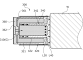
- a cover member 360 is provided with an annular recess 361.
- the annular recess 361 expands the space between the outer cylindrical portion 321 and the inner cylindrical portion 322 of the case 320 to the left.
- the inner diameter portion of the annular recess 361 is arranged on the inner diameter side of the inner peripheral surface of the small diameter portion 342 of the piston 340 .
- a cover 362 is provided on the left side of the lid member 360 to cover an end surface of the lid member 360.
- Example 5 a pressurizing device according to Example 5 will be described with reference to FIGS. 7 and 8. Note that explanations of the same and overlapping configurations as those of the fourth embodiment will be omitted. Further, in FIG. 8, illustrations of the through hole 260a and the plug 270 are omitted.
- the pressurizing device 400 of the fifth embodiment includes a pair of cases 420A and 420B as cylinder parts, a pair of pistons 440A and 440B, and a guide body. It is mainly composed of a pair of cylindrical bodies 450A and 450B as pressure transmitters and a pair of lid members 460A and 460B as pressure transmitters.
- the piston 440A has almost the same shape as the piston 340 of Example 4, and is composed of a large diameter portion 441A and a small diameter portion 442A.
- Piston 440B similarly includes a large diameter portion 441B and a small diameter portion 442B.
- the large diameter portions 441A, 441B are provided with through holes 443A, 443B that penetrate in the axial direction.
- the left end portion of the cylindrical body 450A is fixed to the outer peripheral surface of the large diameter portion 441A of the piston 440A.
- the right end portion of the cylindrical body 450B is fixed to the outer peripheral surface of the large diameter portion 441B of the piston 440B.
- the pressure accumulator 412 of the fifth embodiment has a larger volume than the pressure accumulator 210 of the third embodiment, with the internal spaces of the left and right cases 420A, 420B and the internal spaces of the left and right pistons 440A, 440B communicating with each other. Therefore, fluctuations in the pressure within the pressure accumulating section 412 due to expansion and contraction of the pressurizing device 400 can be suppressed, and the operated objects WA and WB can be pressurized with high accuracy.
- the internal spaces of the cases 420A, 420B and the internal spaces of the left and right pistons 440A, 440B may be made non-communicating by closing the through holes 443A, 443B with plugs.
- the fixing plate 550 is fixed to the object to be fixed. According to this, the piston 540 does not move in the axial direction even if the expansion and contraction widths of the actuated bodies WA' and WB' are different, so that it is possible to stably pressurize the actuated bodies WA' and WB'. Become.
- the pressure transmitting body is a piston. It may be a pressure transmitting body that transforms the pressure by deforming and transmits the changed pressure to the object to be affected.
- Examples 1 to 6 a configuration in which gas is accumulated in the pressure accumulator is exemplified, but a liquid such as oil or a mixture of a liquid and a gas may be sealed in the pressure accumulator.
- the guide may be composed only of a cylinder part and a small diameter part.
- the breathing holes 51, 510 are provided in the cylindrical bodies 5, 50, but the breathing holes 51, 510 are not provided, and the Alternatively, pressure changes in the space 11 may also be utilized.
- the annular recess 3d and the annular recesses 42a and 42c are spaces for fluid reservoirs, but there are parts in the spaces that have a bearing function, parts that improve lubricity, and parts that suppress eccentricity. You may insert parts.
- the small diameter portions 42 and 420 of the pistons 4 and 40 are solid, but the small diameter portions 42 and 420 may have a recessed portion recessed from the left end to the right. In this case, a large volume of the pressure accumulating portion can be ensured.
Landscapes
- Engineering & Computer Science (AREA)
- Mechanical Engineering (AREA)
- Physics & Mathematics (AREA)
- Fluid Mechanics (AREA)
- General Engineering & Computer Science (AREA)
- Actuator (AREA)
- Press Drives And Press Lines (AREA)
- Supply Devices, Intensifiers, Converters, And Telemotors (AREA)
Priority Applications (4)
| Application Number | Priority Date | Filing Date | Title |
|---|---|---|---|
| JP2024528964A JPWO2023243703A1 (https=) | 2022-06-17 | 2023-06-16 | |
| EP23823993.3A EP4542054A4 (en) | 2022-06-17 | 2023-06-16 | PRESSURE APPLICATION DEVICE |
| CN202380046342.4A CN119365688A (zh) | 2022-06-17 | 2023-06-16 | 加压装置 |
| US18/874,903 US20250361887A1 (en) | 2022-06-17 | 2023-06-16 | Pressure applying device |
Applications Claiming Priority (4)
| Application Number | Priority Date | Filing Date | Title |
|---|---|---|---|
| JP2022098428 | 2022-06-17 | ||
| JP2022-098428 | 2022-06-17 | ||
| JP2022-164904 | 2022-10-13 | ||
| JP2022164904 | 2022-10-13 |
Publications (1)
| Publication Number | Publication Date |
|---|---|
| WO2023243703A1 true WO2023243703A1 (ja) | 2023-12-21 |
Family
ID=89191434
Family Applications (1)
| Application Number | Title | Priority Date | Filing Date |
|---|---|---|---|
| PCT/JP2023/022371 Ceased WO2023243703A1 (ja) | 2022-06-17 | 2023-06-16 | 加圧装置 |
Country Status (5)
| Country | Link |
|---|---|
| US (1) | US20250361887A1 (https=) |
| EP (1) | EP4542054A4 (https=) |
| JP (1) | JPWO2023243703A1 (https=) |
| CN (1) | CN119365688A (https=) |
| WO (1) | WO2023243703A1 (https=) |
Cited By (1)
| Publication number | Priority date | Publication date | Assignee | Title |
|---|---|---|---|---|
| WO2025253939A1 (ja) * | 2024-06-06 | 2025-12-11 | イーグル工業株式会社 | 加圧装置 |
Citations (3)
| Publication number | Priority date | Publication date | Assignee | Title |
|---|---|---|---|---|
| JPH08226401A (ja) * | 1994-10-11 | 1996-09-03 | Pneumatic Energy Inc | 流体作動装置 |
| CN105545858A (zh) * | 2016-02-03 | 2016-05-04 | 山东科技大学 | 一种气-液增压缸专用气控阀及气-液增压缸 |
| JP2021020224A (ja) | 2019-07-24 | 2021-02-18 | 芝浦機械株式会社 | 局部加圧装置 |
Family Cites Families (9)
| Publication number | Priority date | Publication date | Assignee | Title |
|---|---|---|---|---|
| US1289795A (en) * | 1918-03-08 | 1918-12-31 | Henry Johnson | Jack. |
| FR1024818A (fr) * | 1950-09-22 | 1953-04-07 | Amortisseur de chocs pneumatique à détente freinée pneumatiquement | |
| US2786409A (en) * | 1953-06-15 | 1957-03-26 | Robert W Claire | Pneumatic dental press |
| FR2533644B1 (fr) * | 1982-09-28 | 1986-12-19 | Snecma | Verin hydraulique a chambres multiples coaxiales et systemes de commande par verins synchronises de ce type |
| GB9314145D0 (en) * | 1993-07-08 | 1993-08-18 | Savair Ltd | Pneumatic cylinder and control valve therefor |
| NO320025B1 (no) * | 2003-06-23 | 2005-10-10 | Per Jorgen Myrhe | Anordning ved en gravemaskin |
| DE102011119011A1 (de) * | 2011-11-14 | 2013-05-16 | Hydac Technology Gmbh | Gaszylinder, insbesondere Hochdruck-Gaszylinder |
| US8944157B2 (en) * | 2012-07-11 | 2015-02-03 | Jacob MAIL | Hydro pneumatic lifting system and method |
| WO2019152852A2 (en) * | 2018-02-01 | 2019-08-08 | Vanderbilt University | Cylinder actuator |
-
2023
- 2023-06-16 EP EP23823993.3A patent/EP4542054A4/en active Pending
- 2023-06-16 WO PCT/JP2023/022371 patent/WO2023243703A1/ja not_active Ceased
- 2023-06-16 CN CN202380046342.4A patent/CN119365688A/zh active Pending
- 2023-06-16 JP JP2024528964A patent/JPWO2023243703A1/ja active Pending
- 2023-06-16 US US18/874,903 patent/US20250361887A1/en active Pending
Patent Citations (3)
| Publication number | Priority date | Publication date | Assignee | Title |
|---|---|---|---|---|
| JPH08226401A (ja) * | 1994-10-11 | 1996-09-03 | Pneumatic Energy Inc | 流体作動装置 |
| CN105545858A (zh) * | 2016-02-03 | 2016-05-04 | 山东科技大学 | 一种气-液增压缸专用气控阀及气-液增压缸 |
| JP2021020224A (ja) | 2019-07-24 | 2021-02-18 | 芝浦機械株式会社 | 局部加圧装置 |
Non-Patent Citations (1)
| Title |
|---|
| See also references of EP4542054A4 |
Cited By (1)
| Publication number | Priority date | Publication date | Assignee | Title |
|---|---|---|---|---|
| WO2025253939A1 (ja) * | 2024-06-06 | 2025-12-11 | イーグル工業株式会社 | 加圧装置 |
Also Published As
| Publication number | Publication date |
|---|---|
| JPWO2023243703A1 (https=) | 2023-12-21 |
| EP4542054A1 (en) | 2025-04-23 |
| US20250361887A1 (en) | 2025-11-27 |
| CN119365688A (zh) | 2025-01-24 |
| EP4542054A4 (en) | 2026-03-11 |
Similar Documents
| Publication | Publication Date | Title |
|---|---|---|
| CN108779859B (zh) | 密封结构 | |
| WO2012056647A1 (ja) | 減圧弁 | |
| US8720902B2 (en) | Pressure balanced radial rotary shaft seal | |
| WO2023243703A1 (ja) | 加圧装置 | |
| JP2019158068A (ja) | ショックアブソーバ | |
| JP2005172128A (ja) | 油入緩衝器 | |
| WO2018056216A1 (ja) | ショックアブソーバ | |
| US20080217127A1 (en) | Shock absorber | |
| WO2023243704A1 (ja) | 加圧装置 | |
| US5431014A (en) | Master cylinder | |
| JP6749499B2 (ja) | マスタシリンダ | |
| JP6554000B2 (ja) | ショックアブソーバ | |
| JP7116646B2 (ja) | ダンパ | |
| JP7769522B2 (ja) | シリンダ装置 | |
| WO2025253939A1 (ja) | 加圧装置 | |
| JP2018048719A (ja) | 緩衝器 | |
| JP4683627B2 (ja) | 位置決め構造 | |
| JPH07174251A (ja) | 定量バルブ | |
| JP4761466B2 (ja) | 空圧緩衝器 | |
| JP7089403B2 (ja) | ダンパ | |
| JP4955912B2 (ja) | シール・ガイド装置 | |
| JP2002257178A (ja) | シリンダ装置 | |
| JPH11280710A (ja) | シリンダ装置 | |
| JP2019199954A (ja) | 流体圧シリンダ | |
| JPS623323B2 (https=) |
Legal Events
| Date | Code | Title | Description |
|---|---|---|---|
| 121 | Ep: the epo has been informed by wipo that ep was designated in this application |
Ref document number: 23823993 Country of ref document: EP Kind code of ref document: A1 |
|
| WWE | Wipo information: entry into national phase |
Ref document number: 2024528964 Country of ref document: JP |
|
| WWE | Wipo information: entry into national phase |
Ref document number: 202380046342.4 Country of ref document: CN |
|
| WWE | Wipo information: entry into national phase |
Ref document number: 18874903 Country of ref document: US |
|
| WWE | Wipo information: entry into national phase |
Ref document number: 2023823993 Country of ref document: EP |
|
| NENP | Non-entry into the national phase |
Ref country code: DE |
|
| WWP | Wipo information: published in national office |
Ref document number: 202380046342.4 Country of ref document: CN |
|
| ENP | Entry into the national phase |
Ref document number: 2023823993 Country of ref document: EP Effective date: 20250117 |
|
| WWP | Wipo information: published in national office |
Ref document number: 2023823993 Country of ref document: EP |
|
| WWP | Wipo information: published in national office |
Ref document number: 18874903 Country of ref document: US |