WO2023243285A1 - 演出出力玩具及び玩具別体 - Google Patents
演出出力玩具及び玩具別体 Download PDFInfo
- Publication number
- WO2023243285A1 WO2023243285A1 PCT/JP2023/018201 JP2023018201W WO2023243285A1 WO 2023243285 A1 WO2023243285 A1 WO 2023243285A1 JP 2023018201 W JP2023018201 W JP 2023018201W WO 2023243285 A1 WO2023243285 A1 WO 2023243285A1
- Authority
- WO
- WIPO (PCT)
- Prior art keywords
- toy
- color
- sheet
- colors
- separate
- Prior art date
- Legal status (The legal status is an assumption and is not a legal conclusion. Google has not performed a legal analysis and makes no representation as to the accuracy of the status listed.)
- Ceased
Links
Images


Classifications
-
- A—HUMAN NECESSITIES
- A63—SPORTS; GAMES; AMUSEMENTS
- A63H—TOYS, e.g. TOPS, DOLLS, HOOPS OR BUILDING BLOCKS
- A63H33/00—Other toys
- A63H33/22—Optical, colour, or shadow toys
-
- A—HUMAN NECESSITIES
- A63—SPORTS; GAMES; AMUSEMENTS
- A63H—TOYS, e.g. TOPS, DOLLS, HOOPS OR BUILDING BLOCKS
- A63H33/00—Other toys
-
- A—HUMAN NECESSITIES
- A63—SPORTS; GAMES; AMUSEMENTS
- A63H—TOYS, e.g. TOPS, DOLLS, HOOPS OR BUILDING BLOCKS
- A63H5/00—Musical or noise- producing devices for additional toy effects other than acoustical
Definitions
- Patent Document 1 proposes a moving toy that outputs light and sound from the toy body depending on the type of removable article attached to the toy body.
- the present invention provides a novel mechanism for realizing a performance, for example, in a performance output toy.
- the present invention is, for example, a production output toy, which includes a toy main body having a light emitting section capable of emitting light in a plurality of colors and a control section controlling production using the light emitting section, and a toy body that is detachable from the toy main body. and one or more separate toy bodies that are capable of transmitting light emitted from the light emitting part when attached to the toy main body, and each of the one or more separate toy bodies has complementary colors that are different from each other and that transmit light emitted from the light emitting part when attached to the toy main body.
- the present invention is characterized by comprising a presentation member formed using the same method.
- the present invention provides a separate toy that is attached to a toy main body, and includes, for example, a light emitting section that can emit light in a plurality of colors, and a control section that controls effects using the light emitting section,
- the present invention is characterized by comprising a presentation member formed using mutually different complementary colors that transmits the irradiated light from the light emitting section when attached to the device.
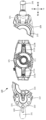
- FIG. 3 is a diagram showing how the presentation member is attached and detached according to an embodiment.
- FIG. 3 is a diagram illustrating a configuration example of a complementary color gimmick according to an embodiment.
- FIG. 3 is a diagram illustrating a configuration example of a complementary color gimmick according to an embodiment.
- FIG. 3 is a diagram showing correspondence information stored in a storage unit and a production pattern realized by a program according to an embodiment.
- 5 is a flowchart showing a processing procedure of a control unit according to an embodiment.
- FIG. 1(a) shows a front external appearance of the performance output toy 100
- FIG. 1(b) shows a plan view of the external appearance of the performance output toy 100. Note that the up and down, left and right, and front and back arrows indicate the direction of the performance output toy in the figure, and the same applies to other figures.
- the performance output toy 100 includes a toy main body 101 and separate toy bodies 102 and 103.
- the production output toy 100 according to this embodiment will be described as a buckle attached to a belt.
- the toy main body 101 is composed of a base 111 and a main body 112, and separate toy bodies 102 and 103 are attached to the main body 112.
- the main body part 112 is configured to be rotatable relative to the base part 111, and can rotate relative to the base part 111, including the separate toys 102 and 103 attached to the main body part 112.
- the toy separate bodies 102 and 103 can be individually attached to and detached from the toy body 101, and many variations may be provided as optional devices of the production output toy.
- the performance output toy 100 outputs various performances using light, sound, display, vibration, etc., depending on the separate toys 102 and 103 attached to the toy main body 101.
- the toy main body 101 is provided with a light emitting section that can emit light in multiple colors and a control section for controlling effects, and outputs various effects depending on the attached toy. do.
- the separate toys 102 and 103 are equipped with production members having a simple structure to enable various productions, but are also equipped with a light emitting section and a control section like the toy main body 101. It can be manufactured relatively cheaply. Therefore, many variations of separate toys can be easily provided in order to realize a variety of performance patterns.
- the separate toys 102 and 103 may be provided with a light emitting section, a sounding section, a control section, and the like.
- FIG. 2 shows the toy main body 101 and separate toy bodies 102 and 103 before attachment.
- the toy main body 101 includes a production section 211, mounting sections 212a and 212b, and detection sections 213a and 213b.
- the production unit 211 is provided with devices related to production, particularly a light emitting unit, a sensor, and a switch. Details of the production section 211 will be described later using FIG. 3.
- Separate toys 102 and 103 can be attached to the attachment parts 212a and 212b, respectively. Note that any separate toy 102, 103 may be attached to each attachment part 212a, 212b. Further, two separate toys of the same type, for example, two separate toys 102, may be attached to the mounting portions 212a and 212b.
- the detection units 213a and 213b individually recognize the separate toys attached to the attachment units 212a and 212b, respectively.
- the detection units 213a and 213b are sensors that read identification units 225 and 235 provided on separate toys, which will be described later.
- the sensor any type of sensor can be used depending on the form of the identification section.
- various sensors such as an infrared sensor, a laser sensor, a camera sensor, a contact type sensor, an ultrasonic sensor, and a radio wave sensor can be used.
- the separate toy 102 includes a grip 221 , a rotating member 222 , a presentation member 223 , a switch 224 , and an identification section 225 .
- the grip 221 is held by the operator when rotating the base 111 of the toy body 101.
- a switch 224 is provided on the grip 221, and when pressed by the operator, a production output can be activated.
- the rotating member 222 is rotatably attached, and when rotated while attached to the toy body 101, a switch 214a provided on the toy body 101, which will be described later, can be operated.
- the presentation member 223 is formed in a semicircular shape, and holds therein at least two color formation layers of mutually different colors that are in a complementary color relationship and are superimposed.
- overlapping is not limited to the formation layers of two colors being arranged in close contact with each other, but the formation layers of another color being sandwiched between the formation layers of two colors. It can also include form. Furthermore, when superimposing two colored formation layers, two sheets (two sheets) each formed of two different colors may be superimposed, or one sheet (one sheet) may be superimposed. It may be formed by overlapping two color forming layers.
- the performance member is made of a member that can transmit light, and can transmit light emitted from light emitting sections 215b and 215c, which will be described later, provided on the toy main body 101. At that time, a variety of effects can be achieved by changing (absorbing) the color of the irradiated light using a sheet installed inside.
- identification section 225 identification information for identifying the separate toy 102 is formed.
- the identification section 225 is formed in any form according to the method of the detection sections 213a and 213b, and includes, for example, a numerical value, a character string, a bar code, etc. representing identification information, or a physical unevenness. It may be formed as an IC tag, an infrared transmitter, or the like.
- the separate toy 103 includes a grip 231, a presentation member 233, and an identification section 235.
- the grip 231 is a member that is held by the operator similarly to the grip 221, and the grip 231 itself is formed to be rotatable. By rotating the grip 231 itself, the production output can be activated.
- the effect member 233 has the same configuration as the effect member 223, and when the toy separate bodies 102 and 103 are attached to the toy main body 101, the effect member 233 comes into contact with the effect member 223 to form a circular effect part.
- the identification unit 235 has a similar configuration to the identification unit 225.
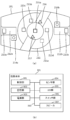
- FIG. 3(a) shows an external plan view of the toy main body 101.
- FIG. 3(b) shows a block diagram of the control configuration of the toy main body 101.
- the toy main body 101 includes, in addition to the above-described detection units 213a and 213b, detection units 216 and 217, switches 214a and 214b, and light emitting units 215a to 215e as components related to production output. It further includes: The detection units 216, 217 and the light emitting units 215a to 215e are provided inside the presentation unit 211. The detection unit 216 detects that the main body portion 112 of the toy main body 101 has rotated with respect to the base portion 111.
- the detection unit 216 is, for example, a push-down type sensor, and the detection unit 216 is pressed down every time the main body 112 rotates 180 degrees with respect to the base 111, and outputs a detection signal to the control unit 301, which will be described later.
- the detection unit 217 detects its identification information.
- the detection unit 217 may have the same configuration as the detection units 213a and 213b. Further, the production output toy 100 may be configured to output production according to the detected identification information when the circular production member is fitted.
- the switch 214a is a switch that is pressed down by clockwise or counterclockwise rotation of the rotating member 222 of the separate toy 102.
- the switch 214b is a switch that is pressed down when the grip 231 of the separate toy 103 is rotated.
- the light emitting units 215a to 215e can emit light in a plurality of colors, and may employ full-color LEDs (light emitting diodes), for example.
- the light emitting units 215a to 215e may be controlled individually or may be controlled in a unified manner. Note that in the case of individual control, the timing and color of light emission can be individually controlled, so more diverse effects can be realized.
- the light emitting section 215a is arranged inside a circular shape located at the center of the presentation section 211. When the circular effect member is fitted, it emits light under the control of a control section, which will be described later.
- the light emitting parts 215b and 215c are disposed below the presentation member 223 of the separate toy 102 when the separate toy 102 is attached to the toy main body 101, and by emitting light, the sheet provided on the presentation member 223 is illuminated. It is possible to output the performance by passing through the .
- the light emitting parts 215d and 215e are disposed below the presentation member 233 of the separate toy 103 when the separate toy 103 is attached to the toy main body 101, and by emitting light, the sheet provided on the presentation member 233 is illuminated. It is possible to output the performance by passing through the .
- the toy main body 101 includes a control section 301, a storage section 302, a power supply section 303, a sensor group 304, an LED group 305, a switch group 306, and a speaker 307 as control components.
- the sensor group 304 corresponds to the detection units 213a, 213b, 216, and 217.
- the LED group 305 corresponds to the light emitting sections 215a to 215e.
- the control unit 301 is constituted by a microprocessor or the like, and controls the performance output of the performance output toy 100 by reading and executing a program stored in the storage unit 302.
- the storage unit 302 includes various memories such as ROM (Read Only Memory) and RAM (Random Access Memory), and the control unit 301 It stores various data such as a program executed by the speaker 307, sound data outputted from the speaker 307, and correspondence information linking identification information of a separate toy with information of a program to be executed. Details of the program and corresponding information will be described later.
- the power supply section 303 supplies power to the toy main body 101, and is preferably realized by a battery in order to maintain portability, but the present invention is not limited to this, and any type of power supply may be applied. be able to.
- the battery may be of a rechargeable type.
- the sensor group 304 outputs a detection signal to the control unit 301 in response to detection by each sensor (detection unit).
- the LED group 305 emits light in a predetermined color and at a predetermined timing according to instructions from the control unit 301.
- the switch group 306 outputs a signal to the control unit 301 at the timing when each switch is pressed.
- the speaker 307 is controlled by the control unit 301 and outputs sound according to the sound data stored in the storage unit 302.
- the separate toy body 102 is attached to the toy main body 101, as shown in FIG. 4(b).
- the rotating member 222 can be rotated as shown by the dotted arrow 401 or the switch 224 can be operated.
- an operation signal is transmitted from each switch 224, 214a to the control unit 301, and a performance output corresponding to the operation is activated.
- only one separate toy 102 is attached to the toy main body 101.
- control section 301 controls the light emitting sections 215a to 215c to emit light and the light emitting sections 215d and 215e to not emit light. It's okay.
- control unit 301 may control all the light emitting units 215a to 215e to emit light even when one separate toy is attached.
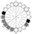
- FIG. 5 shows an example of a hue wheel.
- FIG. 5 shows an example of a hue wheel of 20 colors.
- color variations are represented by different shading.
- FIG. 5 shows a hue circle based on the Munsell color system as an example of a hue circle.
- the Munsell color system adds intermediate hues (yellow-red YR, yellow-green GY, blue-green BG, blue-violet PB, red-violet RP) to the five basic hues (red R, yellow Y, green G, blue B, purple P). It consists of 20 hues.
- two colors that are directly opposite have a complementary color relationship.
- complementary colors include colors adjacent to the opposite color. For example, red and green are complementary colors.
- red (5R) and blue-green (5BG) indicated by a dotted line 501 are complementary colors.
- yellow-red (10YR) and blue (10B) indicated by a dotted line 502 are complementary colors.
- complementary colors When complementary colors are mixed together, it becomes a gray color (achromatic color) that is very close to black.
- the performance output toy 100 according to the present embodiment realizes various performance patterns using a combination of two complementary colors.
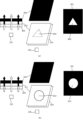
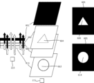
- FIG. 6A shows a configuration for explaining sheets of two complementary colors.
- FIG. 6B shows a structure in which sheets of two complementary colors are integrated, and shows the structure of the sheet member according to this embodiment.
- a configuration will be described in which two sheets formed using two complementary color paints (printed on a transparent sheet) are overlapped, but the present invention is not limited. There is no intention. For example, it may be formed using two colors of paint on one side of one sheet and the other side that is the back side of the one sheet. Alternatively, the respective paints may be printed (coated) on one side of one sheet. Therefore, when one sheet is used, a plurality of layers corresponding to each sheet described below will be formed.
- FIG. 6A(a) shows the presentation configuration of the first color among the two complementary colors.
- 215 indicates one of the light emitting sections 215b to 215e.
- the light emitting unit 215 is, for example, a full color LED, and is capable of emitting light in a plurality of colors.
- a plurality of transparent sheets (sheets that can transmit light) are arranged above the light emitting section 215.
- Sheet 601 is a black transparent sheet.
- the sheet 602 is a sheet formed using a second color paint that is complementary to the first color.
- a transparent region 604 having an arbitrary shape and outlined in white is formed on the surface of the sheet 602 on which the second color paint is formed.
- the outlined transparent area indicates a colorless and transparent area.
- the sheet 603 is a sheet for diffusing the irradiated light from the light emitting section 215.
- Each of the sheets 601 to 603 is a transparent sheet made of a resin such as polycarbonate (PC), polyethylene terephthalate (PET), or polypropylene (PP).
- the sheet 602 is formed (printed) using paints of two complementary colors.
- a colorless and transparent PC sheet printed with a second color paint is used.
- any type of paint may be used as long as it does not significantly reduce the light transmittance through the sheet.
- a sheet that diffuses light is used as the sheet 603, it is not necessary to specifically diffuse light, and for example, a transparent PET sheet may be used.
- a sheet formed using paint is described as an example, but the sheet is not limited to this, and for example, a sheet formed using a black or second color resin material that can transmit light. A sheet may also be used.
- These plurality of sheets (or plurality of layers) 601, 602, and 603 are arranged in an overlapping manner in this order from above.
- a colorless and transparent sheet may be coated with paint in the order of the second color and then black.
- the light emitting section 215 emits light in the first color from the bottom of these sheets 601 to 603.
- the first color irradiation light from the light emitting unit 215 is first diffused by the sheet 603, and then passes through the second color sheet 602 having a complementary color relationship.
- the second color sheet 602 when the irradiation light of the first color passes through the second color sheet having a complementary color relationship, it changes to gray (achromatic) light.
- the portion that has changed to gray (achromatic color) due to the complementary color relationship cannot be clearly seen, and passes through the outlined transparent area 604 of the sheet 602 without being affected by the complementary color relationship.
- the first color of light is projected. Therefore, the first color light is projected onto the black sheet 601, and an arbitrary shape 606 is formed. That is, the sheet 601 is an example of a display section on which effects are output.
- FIG. 6A(b) shows a presentation configuration of a second color that is complementary to the first color.
- the light emitting unit 215 emits light in a second color different from the first color among two complementary colors.
- a first color sheet 611 is arranged between the sheets 601 and 603.
- the sheet 611 is formed in a first color, and a transparent region 612 in an arbitrary shape is formed on a part of its forming surface.
- a sheet formed using paint is described as an example, but the sheet is not limited to this, and for example, a sheet formed using a black or first color resin material that can transmit light. A sheet may also be used.
- the light emitting section 215 emits light in the second color from the bottom of these sheets 601, 611, and 603.
- the second color irradiation light from the light emitting unit 215 is first diffused by the sheet 603, and then passes through the first color sheet 611 having a complementary color relationship.
- the sheet 611 of the first color when the irradiated light of the second color passes through the sheet of the first color having a complementary color relationship, it changes to gray (achromatic) light.
- the irradiation light of the second color passes through the white transparent area 612 of the sheet 611 of the first color while maintaining the second color.
- the irradiated light that has passed through the sheet 611 forms the above arbitrary shape with the second color light. Thereafter, those irradiated lights reach the black sheet 601.
- the black sheet 601 the part that has changed to gray (achromatic color) due to the influence of the complementary color relationship cannot be clearly seen, and passes through the outlined transparent area 612 of the sheet 611 without being affected by the complementary color relationship.
- the second color light is projected. Therefore, the second color light is projected onto the black sheet 601, and an arbitrary shape 614 is formed.
- each color of paint may be formed on one side of a colorless transparent sheet, or one side and the other side which is the back side of the one side. They may be formed using different colored paints. For example, a first color, a second color, and black paint may be layered on a colorless and transparent sheet, or a second color, black paint may be layered on one side of a colorless and transparent sheet, and a first color on the other side. Can be formed using colored paint. Note that the order of arrangement of the first color and second color layers is not particularly limited. Although the black layer is not essential, it is preferable to provide it because it can hide the first and second color layers.
- the black layer be provided above the first and second color layers.
- the complementary color gimmick when realizing the complementary color gimmick with one sheet, it can be realized by forming a layer printed with colorless and transparent paint as a buffer area corresponding to the sheet 603. By realizing the complementary color gimmick on one sheet, it is possible to save space and save costs.
- the color of the light emitted by the light emitting unit 215 can be outputted in two colors and in different shapes in a simple configuration in which a plurality of transparent sheets (or a plurality of layers) are superimposed. This is achieved by switching.
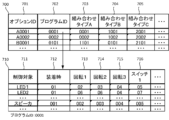
- a table 700 shown in FIG. 7 is information stored in the storage unit 302, and shows correspondence information that links identification information of a separate toy and information of a program to be executed.
- Reference numeral 701 indicates an option ID uniquely assigned to each toy.
- the option ID is identification information that can be obtained by reading the identification section 225 when the separate toy 102 is attached to the toy main body 101, for example.
- This program is a program for controlling production output.
- Table 710 shows an image of a performance pattern realized by one program stored in storage unit 302.
- the performance pattern realized by the program ID "0001" when each trigger occurs is shown.
- Reference numeral 711 indicates a control target at the time of outputting the effect.
- the controlled objects include devices used for outputting effects, such as LEDs and speakers. Other devices may also be included, such as a vibrator that outputs vibrations.
- 712 to 716 indicate identification numbers of production patterns when each trigger occurs.
- one program includes execution programs corresponding to various performance patterns as defined in table 710.
- the control unit 301 executes a corresponding effect pattern included in the program when each trigger occurs.
- Each trigger includes the time of attachment 712, the occurrence of various rotations, and the time of switch operation.
- rotation 1 at 713 indicates a trigger that occurs every time the body portion 112 rotates 180 degrees relative to the base portion 111.
- Reference numeral 714 indicates a trigger that occurs when the switch 214a is operated by rotating the rotating member 222.
- Reference numeral 715 indicates a trigger that occurs when the switch 214b is operated by rotating the grip 231.
- 716 indicates a trigger that occurs when the switch 224 is operated.
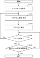
- the control unit 301 determines whether a new event has occurred. As shown in table 710, new events include detection of rotation, operation of a switch, and the like. When a new event occurs, the control unit 301 returns the process to S102 and selects a production pattern corresponding to the corresponding event. Since the subsequent processing is as described above, the explanation will be omitted.
- the production output toy includes a toy main body that has a light emitting section that can emit light in a plurality of colors, a control section that controls production using the light emitting section, and and one or more detachable toy bodies.
- the one or more separate toys include presentation members formed using complementary colors that are different from each other and that transmit the irradiation light from the light emitting part when attached to the toy main body.
- the production member holds at least two complementary colors in a superimposed manner (the production output toy described in 1).
- the control unit causes the light emitted from the light emitting unit to emit light in a complementary color to each of the two superimposed colors of the one or more separate toys attached to the toy body to produce an effect.
- the production output toy according to (2) characterized in that the production output toy is controlled.
- Transparent regions of different shapes are formed on the formation surfaces on which the superimposed two colors are formed, and the transparent regions maintain their colors by the complementary color irradiation light emitted from the light emitting part. 3.
- the sheet member includes two sheets, the first sheet of the two sheets is formed using a first color of the paint of the two colors, and the first of the two sheets is formed using a first color of the paint of the two colors;
- Two toy separate bodies can be attached to the toy body, and when the two toy separate bodies are attached, the control unit is configured to program a program according to the combination of the two toy separate bodies.
- the control unit determines either the timing when the one or more separate toys are attached to the toy main body, or the timing when a switch provided on the one or more separate toys or the toy main body is operated.
- the performance output toy according to any one of (1) to (12), characterized in that a performance is performed using the light emitting section.
- Transparent regions of different shapes are formed on the formation surfaces on which the two superimposed colors are formed, and the transparent regions maintain their colors by the complementary color irradiation light emitted from the light emitting part.
- the separate toy according to (19) or (20), wherein the separate toy is transmitted in a state in which the light is transmitted through the transparent area, and other parts on the forming surface that are different from the transparent area absorb the color of the irradiated light having a complementary color relationship.
- the display section is a black transparent sheet provided at a position where the irradiation light that has passed through the formation surface where the two superimposed colors are formed reaches. Separate toy.
- 100 Production output toy
- 101 Toy main body
- 102, 103 Separate toy
- 211 Production section
- 212a, 212b Mounting section
- 213a, 213b, 216, 217 Detection section
- 214a, 214b Switch, 215a ⁇ 215e: Light emitting part
- 222 Rotating member
Landscapes
- Physics & Mathematics (AREA)
- Engineering & Computer Science (AREA)
- Acoustics & Sound (AREA)
- Multimedia (AREA)
- Toys (AREA)
Abstract
【課題】本発明は、例えば演出出力玩具において、演出を実現する新規な仕組みを提供する。【解決手段】本演出出力玩具は、複数の色で発光可能な発光部と、当該発光部を用いた演出を制御する制御部とを有する玩具本体と、玩具本体に対して着脱可能な1以上の玩具別体とを備える。1以上の玩具別体は、玩具本体に装着された状態で発光部からの照射光を透過する、補色関係にある互いに異なる色を用いて形成された演出部材を備える。
Description
本発明は、演出出力玩具及び玩具別体に関する。
光や音声等による多様な演出を行う各種の玩具が知られている。例えば特許文献1では、玩具本体に装着された着脱物品の種類に応じて、玩具本体から光や音声を出力する動作玩具が提案されている。
上記従来技術では、光や音声を出力するだけであり、より新規な演出を行う仕組みが要望されている。
本発明は、例えば、演出出力玩具において、演出を実現する新規な仕組みを提供する。
本発明は、例えば、演出出力玩具であって、複数の色で発光可能な発光部と、該発光部を用いた演出を制御する制御部とを有する玩具本体と、前記玩具本体に対して着脱可能な1以上の玩具別体と、を備え、前記1以上の玩具別体は、前記玩具本体に装着された状態で前記発光部からの照射光を透過する、補色関係にある互いに異なる色を用いて形成された演出部材を備えることを特徴とする。
また、本発明は、例えば、複数の色で発光可能な発光部と、該発光部を用いた演出を制御する制御部とを有する玩具本体に装着される玩具別体であって、前記玩具本体に装着された状態で前記発光部からの照射光を透過する、補色関係にある互いに異なる色を用いて形成された演出部材を備えることを特徴とする。
本発明によれば、演出出力玩具において、演出を実現する新規な仕組みを提供することができる。
以下、添付図面を参照して実施形態を詳しく説明する。尚、以下の実施形態は特許請求の範囲に係る発明を限定するものではなく、また実施形態で説明されている特徴の組み合わせの全てが発明に必須のものとは限らない。実施形態で説明されている複数の特徴うち二つ以上の特徴が任意に組み合わされてもよい。また、同一若しくは同様の構成には同一の参照番号を付し、重複した説明は省略する。
<演出出力玩具の外観> まず図1を参照して、本実施形態に係る演出出力玩具100の外観構成の一例について説明する。図1(a)は演出出力玩具100の外観正面を示し、図1(b)は演出出力玩具100の外観平面を示す。なお、上下、左右、前後の矢印については図における演出出力玩具の向きを示し、他の図面についても同様である。
演出出力玩具100は、玩具本体101、及び玩具別体102、103を備える。本実施形態に係る演出出力玩具100は、ベルトに装着されるバックルとして説明する。しかし本発明を限定する意図はなく、本発明は任意の玩具に適用することができる。玩具本体101は、基部111と本体部112とから構成され、本体部112に対して玩具別体102、103が装着される。また、本体部112は、基部111に回転可能に構成されており、本体部112に装着された玩具別体102、103を含めて基部111に対して回転することができる。
玩具別体102、103は玩具本体101に対して個別に着脱可能であり演出出力玩具のオプション装置として多くのバリエーションが設けられてもよい。演出出力玩具100は、玩具本体101に装着される玩具別体102、103に応じて、光、音、表示、振動などを用いて様々な演出を出力する。
詳細については後述するが、玩具本体101には、複数の色で発光可能な発光部や、演出を制御するための制御部が設けられ、装着された玩具別体に応じて多様な演出を出力する。一方、本実施形態によれば、玩具別体102、103は、多様な演出を可能とするための簡易的な構造の演出部材を備えるものの、玩具本体101のように発光部や制御部を備えるものではなく、比較的安価に製造することができる。したがって、多様な演出パターンを実現すべく、玩具別体について多くのバリエーションを容易に提供することができる。なお、玩具別体102、103に発光部や発音部、制御部等を設けてもよい。
<演出出力玩具の詳細構成> 次に図2を参照して、本実施形態に係る演出出力玩具100の詳細構成について説明する。図2は、装着前の玩具本体101、玩具別体102、103を示す。
玩具本体101は、演出部211、装着部212a、212b、及び検出部213a、213bを備える。演出部211は、演出に関わるデバイス、特に発光部やセンサ、スイッチが設けられる。演出部211の詳細については図3を用いて後述する。装着部212a、212bには、それぞれ玩具別体102、103が装着可能である。なお、各装着部212a、212bには、何れの玩具別体102、103が装着されてもよい。また、装着部212a、212bに対して同タイプの2つの玩具別体、例えば2つの玩具別体102が装着されてもよい。検出部213a、213bは、それぞれ装着部212a、212bに装着された玩具別体の個別に認識する。例えば、検出部213a、213bは、後述する玩具別体に設けられた識別部225、235を読み取るセンサである。センサとしては、識別部の形態に合わせて任意の方式のセンサを用いることができる。例えば、赤外線センサ、レーザセンサ、カメラセンサ、接触式センサ、超音波センサ、電波センサなど種々のセンサを利用することができる。
玩具別体102は、グリップ221、回転部材222、演出部材223、スイッチ224、及び識別部225を備える。グリップ221は、玩具本体101の基部111に対して回転動作を行う際に操作者によって把持される。グリップ221にはスイッチ224が設けられており、操作者によって押下されると演出出力を発動することができる。回転部材222は、回転可能に取り付けられており、玩具本体101に装着された状態で回転操作が行われると、玩具本体101に設けられた後述するスイッチ214aを操作することができる。本実施形態では、演出部材223は半円形状で形成されており、内部に少なくとも補色関係にある互いに異なる色の2色の形成層を重畳して保持している。なお、本実施形態において「重畳する」とは、2色の形成層が密着して配置されることに限定するものではなく、2色の形成層の間に他の色の形成層が挟み込まれる形態も含みうるものである。また、2色の形成層を重畳する際、互いに異なる色の2色でそれぞれ形成された2つのシート(2枚のシート)を重畳するものでもよいし、1つのシート(1枚のシート)に2色の形成層を重畳して形成するものでもよい。当該演出部材は光を透過可能な部材で構成されており、玩具本体101に設けられた後述する発光部215b、215cからの照射光を透過することができる。その際、内部に設けられたシートによって照射光の色を変化(吸収)させることにより、多様な演出を実現する。識別部225は、玩具別体102を識別するための識別情報が形成される。上述したように、識別部225は検出部213a、213bの方式に合わせて任意の形態で形成されるものであり、例えば、識別情報を表す数値、文字列、バーコード等や、物理的な凹凸の構成、ICタグ、赤外線送信部等として形成されてもよい。
玩具別体103は、グリップ231、演出部材233、及び識別部235を備える。グリップ231は、グリップ221と同様に操作者によって把持される部材であり、さらにグリップ231自体が回転可能に形成される。グリップ231自体を回転することにより、演出出力を発動することができる。演出部材233は、演出部材223と同様の構成であり、玩具別体102、103が玩具本体101に装着されることにより、演出部材223と当接して円形形状の演出部を構成する。識別部235は識別部225と同様の構成である。
<玩具本体の詳細構成> 次に、図3を参照して、本実施形態に係る玩具本体101の詳細構成について説明する。図3(a)は玩具本体101の外観平面を示す。図3(b)は玩具本体101の制御構成のブロック図を示す。
図3(a)に示すように、玩具本体101は、演出出力に関わる構成として、上述した検出部213a、213bに加えて、検出部216、217、スイッチ214a、214b、及び発光部215a~215eを更に備える。検出部216、217、及び発光部215a~215eは演出部211の内側に設けられる。検出部216は、玩具本体101の本体部112が基部111に対して回転したことを検出する。検出部216は、例えば押下式のセンサであり、本体部112が基部111に対して180度回転するごとに当該検出部216が押下され、検出信号を後述する制御部301へ出力する。検出部217は、演出部211の中央に円形形状の演出部材(不図示)が嵌め込まれると、その識別情報を検出する。検出部217は、検出部213a、213bと同様の構成であってもよい。また、演出出力玩具100は、円形形状の演出部材が嵌め込まれると、検出した識別情報に応じた演出出力を発動するようにしてもよい。
スイッチ214aは、玩具別体102の回転部材222の時計回り又は反時計回りの回転によって押下されるスイッチである。一方、スイッチ214bは、玩具別体103のグリップ231が回転されることにより押下されるスイッチである。
発光部215a~215eは、複数の色で発光可能であり、例えば、フルカラーLED(light emitting diode)を採用してもよい。発光部215a~215eは個別に制御されるものであってもよいし、統一して制御されるものであってもよい。なお、個別に制御される場合には、発光のタイミングや色を個別に制御することができるため、より多様な演出を実現することができる。発光部215aは、演出部211の中央に位置する円形形状の内部に配置される。円形形状の演出部材が嵌め込まれると後述する制御部によって制御されて発光される。発光部215b、215cは、玩具別体102が玩具本体101に装着された状態で、玩具別体102の演出部材223の下部に配置されており、発光することにより演出部材223に設けられたシートを通過して演出出力を行うことができる。発光部215d、215eは、玩具別体103が玩具本体101に装着された状態で、玩具別体103の演出部材233の下部に配置されており、発光することにより演出部材233に設けられたシートを通過して演出出力を行うことができる。
図3(b)に示すように、玩具本体101は、制御構成として、制御部301、記憶部302、電源部303、センサ群304、LED群305、スイッチ群306、及びスピーカ307を備える。センサ群304は、検出部213a、213b、216、217に相当する。LED群305は、発光部215a~215eに相当する。
制御部301は、マイクロプロセッサなどにより構成され、記憶部302に記憶されているプログラムを読み出して実行することにより、演出出力玩具100の演出出力を制御する。記憶部302は、ROM(Read Only Memory)、及びRAM(Random Access Memory)などの各種メモリを含み、制御部301
が実行するプログラム、スピーカ307から出力する音データなどの各種データ、及び、玩具別体の識別情報と実行するプログラムの情報とを紐づけた対応情報等を記憶している。当該プログラムや対応情報についての詳細は後述する。電源部303は玩具本体101に電源を供給し、電源としては携帯性を維持するために電池によって実現されることが望ましいが、本発明を限定するものではなく、任意の方式の電源を適用することができる。当該電池については充電式のものであってもよい。
が実行するプログラム、スピーカ307から出力する音データなどの各種データ、及び、玩具別体の識別情報と実行するプログラムの情報とを紐づけた対応情報等を記憶している。当該プログラムや対応情報についての詳細は後述する。電源部303は玩具本体101に電源を供給し、電源としては携帯性を維持するために電池によって実現されることが望ましいが、本発明を限定するものではなく、任意の方式の電源を適用することができる。当該電池については充電式のものであってもよい。
センサ群304は、それぞれのセンサ(検出部)による検出に応じて制御部301に対して検出信号を出力する。LED群305は、制御部301の指示に従って、所定の色及び所定のタイミングで光を照射する。スイッチ群306はそれぞれのスイッチが押下されたタイミングで、その旨を示す信号を制御部301へ出力する。スピーカ307は、制御部301によって制御され、記憶部302に記憶された音データに従って音を出力する。
<演出出力玩具100の操作手順> 次に図4を参照して、本実施形態に係る演出出力玩具の操作手順を説明する。なお、ここで説明する操作は一例であり、本発明を限定するものではなく、本発明における演出出力玩具100は種々の操作を行うことができる。
図4(a)に示すように、玩具本体101に対して玩具別体102が矢印方向に装着される。装着されると、検出部213aによって検出信号及び識別情報が制御部301に伝達される。制御部301は、受信した識別情報に応じて記憶部302から対応するプログラムを読み出して実行することにより、装着時の演出出力を発動させる。
図4(a)の操作が行われると、図4(b)に示すように、玩具本体101に玩具別体102が装着された状態となる。この状態では回転部材222を点線矢印401に示すように回転させたり、スイッチ224を操作することができる。当該操作に応じて各スイッチ224、214aから操作信号が制御部301に伝達され、当該操作に対応する演出出力が発動される。なお、図4(b)の状態では、1つの玩具別体102が玩具本体101に装着されただけとなる。この場合において、発光部215d、215eの位置には玩具別体が装着されていないため、制御部301は、発光部215a~215cを発光させ、発光部215d、215eについては発光させないように制御してもよい。或いは、制御部301は、1つの玩具別体が装着された状態であっても、全ての発光部215a~215eを発光させるように制御してもよい。
続いて、図4(b)に示すように、玩具本体101に対して玩具別体103が矢印方向に装着される。制御部301は、受信した識別情報に応じて記憶部302から対応するプログラムを読み出して実行することにより、装着時の演出出力を発動させる。ここでは、既に玩具別体102が既に装着されているため、発光部215a~215eの全てを発光するようにしてもよい。
図4(b)の操作が行われると、図4(c)に示すように、玩具本体101に2つの玩具別体102、103が装着された状態となる。ここで、玩具別体103のグリップ231を点線矢印402に示すように回転させることができる。当該操作に応じてスイッチ214bから操作信号が制御部301に伝達され、当該操作に対応する演出出力が発動される。
このように、本実施形態に係る演出出力玩具100は種々のスイッチやセンサなどからの出力信号をトリガとして多様な演出出力を発動させることができる。ここでは演出出力を発動させるトリガについて説明したが、以下では発光部215a~215eを用いた演出出力の詳細について説明する。
<色相環> 次に図5を参照して、色相環における補色関係について説明する。図5は色相環の一例を示す。図5では20色の色相環の例を示す。図5では異なる網掛け表示でカラーのバリエーションを表している。
図5では色相環の一例としてマンセル表色系の色相環を示している。マンセル表色系は、基本5色相(赤R・黄Y・緑G・青B・紫P)の中間色相(黄赤YR・黄緑GY・青緑BG・青紫PB・赤紫RP)を加えた20色相からなる。色相環では、正反対に位置する2つの色は補色関係にある。本実施形態において補色とは、正反対の色に隣接する色も含むものとする。例えば、赤と緑は補色の関係にある。位置例えば、点線501に示す赤(5R)及び青緑(5BG)や、点線502に示す黄赤(10YR)及び青(10B)は、それぞれ補色関係にある。補色関係にある色同士が混ざると限りなく黒に近い灰色(無彩色)となる。本実施形態に係る演出出力玩具100は、このような補色関係にある2色の組み合わせを用いて、多様な演出パターンを実現する。
<補色ギミックの詳細構成> 次に図6A及び図6Bを参照して、本実施形態に係る演出部材である補色ギミックを備えた部材の詳細構成について説明する。図6Aは補色関係にある2色それぞれのシートを説明のための構成である。図6Bは補色関係にある2色それぞれのシートを一体化させた構成であり、本実施形態に係るシート部材の構成を示す。なお、本実施形態では補色関係にある2色の塗料のそれぞれを用いて形成(透明シート上に印刷)された2枚のシートを重畳して形成する構成について説明するが、本発明を限定する意図はない。例えば、1枚のシートの一面と当該一面の裏面となる他面とに対して、2色の塗料のそれぞれを用いて形成した形態でもよい。或いは、1枚のシートの一面にそれぞれの塗料を重ねて印刷(塗布)して実現してもよい。したがって、1枚のシートを用いる場合には、以下で説明する各シートに対応する複数の層が形成されることとなる。
図6A(a)は補色関係にある2色のうち、第1色の演出構成を示す。215は、発光部215b~215eの何れかを示す。上述したように、発光部215は例えばフルカラーLEDであり、複数の色で発光可能である。発光部215の上部には、複数の透明シート(光を透過可能なシート)が配置されている。シート601は黒色の透明シートである。シート602は上記第1色と補色関係にある第2色の塗料を用いて形成されたシートである。また、シート602の第2色の塗料の形成面には任意の形状で白抜きされた透明領域604が形成されている。本実施形態において、白抜きされた透明領域とは無色透明の領域を示す。シート603は発光部215から照射光を拡散するためのシートである。各シート601~603は、ポリカーボネート(PC)、ポリエチレンテレフタレート(PET)、ポリプロピレン(PP)等の樹脂等を材料とした透明のシートである。また、シート602は、補色関係にある2色のそれぞれの色の塗料を用いて形成(印刷)されている。図6A(a)においては、無色透明のPCシート上に、第2色の塗料を印刷したものを利用している。塗料については、シートにおける光の透過率を著しく低減させない塗料であれば、任意の種類の塗料が用いられてよい。なお、ここではシート603について光を拡散させるシートを用いた例を説明するが、特に光を拡散する必要はなく、例えば透明なPETシートを用いてもよい。また、本実施形態では、塗料を用いて形成されたシートを一例に説明しているが、これに限られることはなく、例えば、光を透過可能な黒色または第2色の樹脂材料で作成されたシートを用いてもよい。
これらの複数のシート(或いは、複数の層)601、602、603は上からこの順序で重畳して配置されている。なお、ここでは複数のシートを用いて構成する例を説明しているが、1枚の無色透明のシートに対して第2色、黒色の順で塗料を塗布して形成してもよい。発光部215は、これらのシート601~603の下部から上記第1色で発光する。発光部215からの第1色の照射光は、まずシート603で拡散され、続いて補色関係にある第2色のシート602を通過する。第2色のシート602では、第1色である照射光が補色関係にある第2色のシートを通過すると灰色(無彩色)の光に変化する。ここで、灰色(無彩色)の光に変化するとは、本実施形態では、第1色の照射光が第2色のシートを照射した際に、補色関係にある第1色が吸収され、無彩色に見える現象を表現するものである。したがって、当該領域における照射光は、人間の目には黒に近い灰色として認識される。言い換えれば、有彩色の色が認識されない領域となる。一方、第1色の照射光は、第2色のシートの白抜きの透明領域604については第1色を維持した状態で通過する。したがって、シート602を通過した照射光は、第1色の光で上記任意の形状を形成する。その後、それらの照射光は、黒色のシート601へ到達する。黒色のシート601では、補色関係の影響で灰色(無彩色)に変化した部分は明瞭に視認することができず、補色関係の影響を受けることなくシート602の白抜きされた透明領域604を通過した第1色の光が投影される。したがって、黒色のシート601では第1色の光が投影され、任意の形状606が形成される。即ち、シート601は、演出が出力される表示部の一例である。
また、図6A(b)は上記第1色と補色関係にある第2色の演出構成を示す。ここでは、図6A(a)と異なる部分についてのみ説明する。図6A(b)では、発光部215は、補色関係にある2色のうち第1色とは異なる第2色で発光する。また、第2色のシート602に代えて、第1色のシート611がシート601、603の間に配置されている。シート611は第1色で形成され、その形成面の一部が任意の形状で白抜きされた透明領域612が形成されている。なお、本実施形態では、塗料を用いて形成されたシートを一例に説明しているが、これに限られることはなく、例えば、光を透過可能な黒色または第1色の樹脂材料で作成されたシートを用いてもよい。
これらの複数のシート(或いは、複数の層)601、611、603は上からこの順序で重畳して配置されている。発光部215は、これらのシート601、611、603の下部から上記第2色で発光する。発光部215からの第2色の照射光は、まずシート603で拡散され、続いて補色関係にある第1色のシート611を通過する。第1色のシート611では、第2色である照射光が補色関係にある第1色のシートを通過すると灰色(無彩色)の光に変化する。一方、第2色の照射光は、第1色のシート611の白抜きされた透明領域612については第2色を維持した状態で通過する。したがって、シート611を通過した照射光は、第2色の光で上記任意の形状を形成する。その後、それらの照射光は、黒色のシート601へ到達する。黒色のシート601では、補色関係の影響で灰色(無彩色)に変化した部分は明瞭に視認することができず、補色関係の影響を受けることなくシート611の白抜きされた透明領域612を通過した第2色の光が投影される。したがって、黒色のシート601では第2色の光が投影され、任意の形状614が形成される。
続いて、図6Bを用いて本実施形態に係る演出構成(補色ギミック)について説明する。発光部215は、玩具別体102、103が玩具本体101に装着された状態でそれぞれ演出部材223、233が上部に位置する。従って、発光部215から照射された光は、演出部材223、233を照射することになる。
演出部材223、233は、複数のシート(或いは、複数の層)を含んで構成される。例えば、それぞれの演出部材223、233は、上述したシート601~603、611が上からこの順序で重畳して配置されている。なお、シート603については最下層に配置してもよいが、シート602とシート611との緩衝領域としてそれらのシートの間に配置することが望ましい。なお上述したように、ここでは複数のシートを用いた構成で説明するが、1枚の無色透明のシートに複数の異なる色の塗料を印刷して、1枚のシートに対して複数の層を形成した形態であってもよい。1枚のシートに
対して複数の層を形成する場合には、無色透明のシートの一面に各色の塗料を重ねて印刷して形成してもよいし、一面と当該一面の裏面となる他面にそれぞれ異なる色の塗料を用いて形成してもよい。例えば、無色透明のシート上に第1色、第2色、黒色の塗料を積層して形成したり、無色透明のシートの一面に第2色、黒色の塗料を積層し、他面に第1色の塗料を用いて形成することができる。なお、第1色、第2色の層の配置の順序は特に限定されるものではない。また黒色の層は必須ではないが、第1色、第2色の層を目隠しすることができるので設けることが好ましいい。その場合、黒色の層は、第1色、第2色の層よりも上面に設けることが好ましい。なお、補色ギミックを1枚のシートで実現する場合には、シート603に対応する緩衝領域として無色透明の塗料で印刷した層を形成することにより実現することができる。補色ギミックを1枚のシートで実現することにより、省スペース化あるいは省コスト化を実現することができる。
対して複数の層を形成する場合には、無色透明のシートの一面に各色の塗料を重ねて印刷して形成してもよいし、一面と当該一面の裏面となる他面にそれぞれ異なる色の塗料を用いて形成してもよい。例えば、無色透明のシート上に第1色、第2色、黒色の塗料を積層して形成したり、無色透明のシートの一面に第2色、黒色の塗料を積層し、他面に第1色の塗料を用いて形成することができる。なお、第1色、第2色の層の配置の順序は特に限定されるものではない。また黒色の層は必須ではないが、第1色、第2色の層を目隠しすることができるので設けることが好ましいい。その場合、黒色の層は、第1色、第2色の層よりも上面に設けることが好ましい。なお、補色ギミックを1枚のシートで実現する場合には、シート603に対応する緩衝領域として無色透明の塗料で印刷した層を形成することにより実現することができる。補色ギミックを1枚のシートで実現することにより、省スペース化あるいは省コスト化を実現することができる。
上記演出部材223、233において、発光部215を第1色で発光させた場合は図6A(a)と同様に、黒色のシート601に第1色の光が投影され、任意の形状606が形成される。一方、発光部215を第2色で発光させた場合は図6A(b)と同様に、黒色のシート601に第2色の光が投影され、任意の形状614が形成される。このように、本実施形態によれば、2色の異なる形状の演出出力を、複数の透明のシート(或いは、複数の層)を重畳した簡易的な構成において、発光部215による照射光の色を切り替えることにより実現している。なお、任意の形状606、614として、キャラクター、電車、車両、恐竜、動物、記号、数字等の絵柄や模様等を表示することにより、玩具の興趣性を高めることができる。また、任意の形状606、614を玩具別体102、103の種類や形状とそれぞれ関連付けた表示とすることで、より玩具の興趣性を高めることができる。また、上記実施形態では、補色関係にある2色を用いる例を説明したがこれに限られることはなく、3色以上の色を用いて補色ギミックを実現しても良い。
<記憶部> 次に図7を参照して、本実施形態に係る記憶部に記憶された対応情報及びプログラムにより実現する演出パターンについて説明する。
図7に示すテーブル700は、記憶部302に記憶される情報であり、玩具別体の識別情報と実行するプログラムの情報とを紐づけた対応情報を示す。701は玩具別体ごとに固有に割り当てられたオプションIDを示す。当該オブションIDは、例えば玩具別体102が玩具本体101に装着された場合に識別部225を読み取ることにより取得することができる識別情報である。
702は、オプションIDに対応する、記憶部302に記憶されたプログラムを識別するプログラムIDを示す。例えば、オプションID「A0001」が割り当てられた玩具別体が玩具本体101に単独で装着された場合に制御部301が記憶部302から読み出して実行するプログラムID「0001」が定義されている。当該プログラムは演出出力を制御するためのプログラムである。
703~704には、オプションID「A0001」の玩具別体が玩具本体101に装着されている状態で、組み合わせて装着される玩具別体のタイプごとに対応するプログラムIDが定義されている。即ち、2つの玩具別体が玩具本体101に装着された場合のそれらの組み合わせごとに対応して実行されるプログラムを識別するプログラムIDが定義されている。玩具別体のタイプとは、例えば玩具別体102はタイプAであり、玩具別体103はタイプBとなる。なお、本実施形態ではタイプA及びタイプBのみ説明するが、図7にも示すようにさらに多くのタイプを適用することができる。
テーブル710は、記憶部302に記憶される1つのプログラムによって実現される演出パターンのイメージを示す。ここでは、プログラムID「0001」で実現される各トリガ発生時の演出パターンを示す。711は、演出出力時の制御対象を示す。制御対象には、演出出力に用いられるデバイス、例えば、LEDやスピーカなどが含まれる。振動を出力するバイブレータなど、他のデバイスが含まれてもよい。
712~716は、各トリガ発生時に演出パターンの識別番号を示す。例えば、1つのプログラムには、テーブル710に定義されているような各種の演出パターンに対応する実行プログラムが含まれる。制御部301は、各トリガ発生時にプログラムに含まれる対応する演出パターンを実行する。各トリガとしては、装着時712、各種の回転発生時、スイッチ操作時などがある。例えば、713の回転1は、本体部112が基部111に対して180度回転するごとに発生するトリガを示す。714は回転部材222を回転させることによりスイッチ214aが操作された場合に発生するトリガを示す。715はグリップ231を回転させることによりスイッチ214bが操作された場合に発生するトリガを示す。716は、スイッチ224が操作された場合に発生するトリガを示す。
当該プログラムは、各演出パターンごとの動作プログラムを含み、これら複数の動作プログラムのそれぞれにおいて異なる演出出力がプログラムされている。即ち、本実施形態によれば、玩具本体101に装着される玩具別体のタイプに加えて、各トリガ発生時に出力する演出を異ならせることにより、多様の演出出力を容易に実現することができる。
<制御部の処理手順> 次に図8を参照して、本実施形態に係る玩具本体101の制御部による処理手順を説明する。以下で説明する処理は、例えば制御部301が記憶部302に記憶されているプログラムを読み出して実行することにより実現される。各処理のステップ番号については”S”に続く番号で示す。
S101で制御部301は、玩具別体102、103が装着されたタイミングで検出部213a、213bによって識別部225、235から識別情報であるオプションIDを取得する。なお、本処理は、玩具別体が装着されるごとに行われる。続いて、S102で制御部301は、S101で取得したオプションIDに対応するプログラムを記憶部302から読み出す。さらに、玩具別体の装着時においては、テーブル710の712に示すように装着時のトリガが発生したとして、読み出したプログラムの中で該当する番号の演出パターンを選択する。その後、S103で制御部301は、選択した演出パターンのプログラムを実行する。これにより、トリガ(玩具別体の装着など)に応じた演出出力が発動する。
次に、S104で制御部301は、新たなイベントが発生したかどうかを判断する。新たなイベントとは、テーブル710に示すように、回転検出や、スイッチの操作などである。新たなイベントが発生すると、制御部301は処理をS102に戻し、該当するイベントに対応する演出パターンを選択する。その後の処理は上述した通りであるため説明を省略する。
一方、イベントが発生していない場合は、当該玩具別体が玩具本体101から取り外されたか、或いは、取り外されていなくとも最後の操作から所定時間が経過したかどうかを判断する。取り外しや所定時間経過でなければ、処理をS104に戻す。また、取り外し又は所定時間経過であれば、本フローチャートの処理を終了する。
以上説明したように、本実施形態に係る演出出力玩具は、複数の色で発光可能な発光部と、当該発光部を用いた演出を制御する制御部とを有する玩具本体と、玩具本体に対して着脱可能な1以上の玩具別体とを備える。1以上の玩具別体は、玩具本体に装着された状態で発光部からの照射光を透過する、補色関係にある互いに異なる色を用いて形成された演出部材を備える。上記構成を有することにより、本実施形態によれば、演出出力玩具において、より簡易的な構成で多様な演出を実現することができる。また、発光部を有する玩具本体に対して玩具別体が着脱可能であるので、補色ギミック部分を容易に交換可能である。
<実施形態のまとめ> 上記実施形態は以下の演出出力玩具及び玩具別体を少なくとも開示する。
(1)演出出力玩具であって、 複数の色で発光可能な発光部と、該発光部を用いた演出を制御する制御部とを有する玩具本体と、 前記玩具本体に対して着脱可能な1以上の玩具別体と、を備え、 前記1以上の玩具別体は、 前記玩具本体に装着された状態で前記発光部からの照射光を透過する、補色関係にある互いに異なる色を用いて形成された演出部材を備えることを特徴とする演出出力玩具。
(2)前記演出部材は、少なくとも補色関係にある互いに異なる2色を重畳して保持する(1に記載の演出出力玩具。
(3)前記制御部は、前記発光部からの照射光を、前記玩具本体に装着された前記1以上の玩具別体の前記重畳された2色のそれぞれの色の補色で発光させて演出を制御することを特徴とする(2)に記載の演出出力玩具。
(4)前記重畳された2色がそれぞれ形成された形成面には、それぞれ異なる形状の透明領域が形成され、 前記透明領域は前記発光部から照射される補色の照射光をその色を維持した状態で透過させ、形成面上の該透明領域とは異なる他の部分は補色関係にある照射光の色を吸収することを特徴とする(3)に記載の演出出力玩具。
(5)前記1以上の玩具別体は、前記重畳された2色がそれぞれ形成された形成面を通過した前記発光部からの照射光に応じて、前記透明領域に形成された形状を表示する表示部を更に備えることを特徴とする(4)に記載の演出出力玩具。
(6)前記表示部は、前記重畳された2色がそれぞれ形成された形成面を通過した照射光が到達する位置に設けられた黒色の透明シートであることを特徴とする(5)に記載の演出出力玩具。
(7)前記演出部材は、補色関係にある互いに異なる色の2色の塗料を用いて形成されたシート部材を含む(2)乃至(6)の何れか1つに記載の演出出力玩具。
(8)前記シート部材は、1枚のシートを含み、前記2色の塗料のうち第1色の塗料を用いて前記1枚のシートの一面が形成され、前記第1色とは異なる第2色の塗料を更に重ねて形成されるか、或いは、前記第1色の塗料を用いて前記1枚のシートの一面が形成され、前記第2色の塗料を用いて前記1枚のシートの前記一面の裏面となる他面が形成されることを特徴とする(7)に記載の演出出力玩具。
(9)前記シート部材は、2枚のシートを含み、前記2色の塗料のうち第1色を用いて前記2枚のシートのうちの第1シートが形成され、前記2色の塗料のうち前記第1色とは異なる第2色の塗料を用いて前記2枚のシートのうちの前記第1シートとは異なる第2シートが形成されることを特徴とする(7)に記載の演出出力玩具。
(10)前記1以上の玩具別体は、固有の識別情報を示す識別部を更に備え、 前記玩具本体は、前記1以上の玩具別体が装着された際に前記識別部を読み取る検出部を更に備え、 前記制御部は、前記検出部によって読み取った識別情報に応じて、対応する玩具別体に設けられた前記演出部材の前記重畳された2色の色に合わせて、前記発光部からの照射光の色を所定のタイミングで切り替えて演出を制御することを特徴とする(2)乃至(9)の何れか1つに記載の演出出力玩具。
(11)前記玩具本体は、前記識別情報に応じたプログラムを記憶した記憶部をさらに備え、 前記制御部は、前記検出部によって読み取った識別情報に応じて、前記記憶部から対応するプログラムを読み出して実行することにより、前記発光部を用いた演出を制御することを特徴とする(10に記載の演出出力玩具。
(12)前記玩具本体には2つの玩具別体が装着可能であり、 前記制御部は、前記2つの玩具別体が装着された場合には、該2つの玩具別体の組み合わせに応じたプログラムを前記記憶部か
ら読み出して実行することにより、前記発光部を用いた演出を制御することを特徴とする(11)に記載の演出出力玩具。
ら読み出して実行することにより、前記発光部を用いた演出を制御することを特徴とする(11)に記載の演出出力玩具。
(13)前記制御部は、前記1以上の玩具別体が前記玩具本体に装着されたタイミング、及び前記1以上の玩具別体又は前記玩具本体に設けられたスイッチが操作されたタイミングの何れかにおいて前記発光部を用いた演出を行うことを特徴とする(1)乃至(12)の何れか1つに記載の演出出力玩具。
(14)前記玩具本体は、音を出力するスピーカを更に備え、 前記制御部は、前記発光部に加えて、前記スピーカを用いて演出を制御することを特徴とする(1)乃至(13)の何れか1つに記載の演出出力玩具。
(15)前記演出出力玩具は、ベルトに装着されるバックルであることを特徴とする(1)乃至(14)の何れか1つに記載の演出出力玩具。
(16)複数の色で発光可能な発光部と、該発光部を用いた演出を制御する制御部とを有する玩具本体に装着される玩具別体であって、 前記玩具本体に装着された状態で前記発光部からの照射光を透過する、補色関係にある互いに異なる色を用いて形成された演出部材を備えることを特徴とする玩具別体。
(17)前記演出部材は、少なくとも補色関係にある互いに異なる2色を重畳して保持する(16)に記載の玩具別体。
(18)前記演出部材は、補色関係にある互いに異なる色の2色の塗料を用いて形成されたシート部材を含む(17)に記載の玩具別体。
(19)前記シート部材は、1枚のシートを含み、前記2色の塗料のうち第1色の塗料を用いて前記1枚のシートの一面が形成され、前記第1色とは異なる第2色の塗料を更に重ねて形成されるか、或いは、前記第1色の塗料を用いて前記1枚のシートの一面が形成され、前記第2色の塗料を用いて前記1枚のシートの前記一面の裏面となる他面が形成されることを特徴とする(18)に記載の玩具別体。
(20)前記シート部材は、2枚のシートを含み、前記2色の塗料のうち第1色を用いて前記2枚のシートのうちの第1シートが形成され、前記2色の塗料のうち前記第1色とは異なる第2色の塗料を用いて前記2枚のシートのうちの前記第1シートとは異なる第2シートが形成されることを特徴とする(18)に記載の玩具別体。
(21)前記重畳された2色がそれぞれ形成された形成面には、それぞれ異なる形状の透明領域が形成され、 前記透明領域は前記発光部から照射される補色の照射光をその色を維持した状態で透過させ、形成面上の該透明領域とは異なる他の部分は補色関係にある照射光の色を吸収することを特徴とする(19)又は(20)に記載の玩具別体。
(22)前記重畳された2色がそれぞれ形成された形成面を通過した前記発光部からの照射光に応じて、前記透明領域に形成された形状を表示する表示部を更に備えることを特徴とする(21)に記載の玩具別体。
(23)前記表示部は、前記重畳された2色がそれぞれ形成された形成面を通過した照射光が到達する位置に設けられた黒色の透明シートであることを特徴とする(22)に記載の玩具別体。
(24)前記重畳された2色に応じた固有の識別情報を示す識別部を更に備え、 前記識別部から読み取られた前記識別情報に応じて前記発光部からの色が切り替えられることを特徴とする(18)乃至(23)の何れか1つに記載の玩具別体。
100:演出出力玩具、101:玩具本体、102、103:玩具別体、211:演出部、212a、212b:装着部、213a、213b、216、217:検出部、214a、214b:スイッチ、215a~215e:発光部、221、231:グリップ、222:回転部材、223、233:演出部材、224:スイッチ、225、235:識別部
Claims (24)
- 演出出力玩具であって、 複数の色で発光可能な発光部と、該発光部を用いた演出を制御する制御部とを有する玩具本体と、 前記玩具本体に対して着脱可能な1以上の玩具別体と、を備え、 前記1以上の玩具別体は、 前記玩具本体に装着された状態で前記発光部からの照射光を透過する、補色関係にある互いに異なる色を用いて形成された演出部材を備えることを特徴とする演出出力玩具。
- 前記演出部材は、少なくとも補色関係にある互いに異なる2色を重畳して保持することを特徴とする請求項1に記載の演出出力玩具。
- 前記制御部は、前記発光部からの照射光を、前記玩具本体に装着された前記1以上の玩具別体の前記重畳された2色のそれぞれの色の補色で発光させて演出を制御することを特徴とする請求項2に記載の演出出力玩具。
- 前記重畳された2色がそれぞれ形成された形成面には、それぞれ異なる形状の透明領域が形成され、 前記透明領域は前記発光部から照射される補色の照射光をその色を維持した状態で透過させ、形成面上の該透明領域とは異なる他の部分は補色関係にある照射光の色を吸収することを特徴とする請求項3に記載の演出出力玩具。
- 前記1以上の玩具別体は、前記重畳された2色がそれぞれ形成された形成面を通過した前記発光部からの照射光に応じて、前記透明領域に形成された形状を表示する表示部を更に備えることを特徴とする請求項4に記載の演出出力玩具。
- 前記表示部は、前記重畳された2色がそれぞれ形成された形成面を通過した照射光が到達する位置に設けられた黒色の透明シートであることを特徴とする請求項5に記載の演出出力玩具。
- 前記演出部材は、補色関係にある互いに異なる色の2色の塗料を用いて形成されたシート部材を含むことを特徴とする請求項2に記載の演出出力玩具。
- 前記シート部材は、1枚のシートを含み、 前記2色の塗料のうち第1色の塗料を用いて前記1枚のシートの一面が形成され、前記第1色とは異なる第2色の塗料を更に重ねて形成されるか、或いは、前記第1色の塗料を用いて前記1枚のシートの一面が形成され、前記第2色の塗料を用いて前記1枚のシートの前記一面の裏面となる他面が形成されることを特徴とする請求項7に記載の演出出力玩具。
- 前記シート部材は、2枚のシートを含み、 前記2色の塗料のうち第1色を用いて前記2枚のシートのうちの第1シートが形成され、前記2色の塗料のうち前記第1色とは異なる第2色の塗料を用いて前記2枚のシートのうちの前記第1シートとは異なる第2シートが形成されることを特徴とする請求項7に記載の演出出力玩具。
- 前記1以上の玩具別体は、固有の識別情報を示す識別部を更に備え、 前記玩具本体は、前記1以上の玩具別体が装着された際に前記識別部を読み取る検出部を更に備え、 前記制御部は、前記検出部によって読み取った識別情報に応じて、対応する玩具別体に設けられた前記演出部材の前記重畳された2色の色に合わせて、前記発光部からの照射光の色を所定のタイミングで切り替えて演出を制御することを特徴とする請求項2乃至9の何れか1項に記載の演出出力玩具。
- 前記玩具本体は、前記識別情報に応じたプログラムを記憶した記憶部をさらに備え、 前記制御部は、前記検出部によって読み取った識別情報に応じて、前記記憶部から対応するプログラムを読み出して実行することにより、前記発光部を用いた演出を制御することを特徴とする請求項10に記載の演出出力玩具。
- 前記玩具本体には2つの玩具別体が装着可能であり、 前記制御部は、前記2つの玩具別体が装着された場合には、該2つの玩具別体の組み合わせに応じたプログラムを前記記憶部から読み出して実行することにより、前記発光部を用いた演出を制御することを特徴とする請求項11に記載の演出出力玩具。
- 前記制御部は、前記1以上の玩具別体が前記玩具本体に装着されたタイミング、及び前記1以上の玩具別体又は前記玩具本体に設けられたスイッチが操作されたタイミングの何れかにおいて前記発光部を用いた演出を行うことを特徴とする請求項10に記載の演出出力玩具。
- 前記玩具本体は、音を出力するスピーカを更に備え、 前記制御部は、前記発光部に加えて、前記スピーカを用いて演出を制御することを特徴とする請求項10に記載の演出出力玩具。
- 前記演出出力玩具は、ベルトに装着されるバックルであることを特徴とする請求項10に記載の演出出力玩具。
- 複数の色で発光可能な発光部と、該発光部を用いた演出を制御する制御部とを有する玩具本体に装着される玩具別体であって、 前記玩具本体に装着された状態で前記発光部からの照射光を透過する、補色関係にある互いに異なる色を用いて形成された演出部材を備えることを特徴とする玩具別体。
- 前記演出部材は、少なくとも補色関係にある互いに異なる2色を重畳して保持することを特徴とする請求項16に記載の玩具別体。
- 前記演出部材は、補色関係にある互いに異なる色の2色の塗料を用いて形成されたシート部材を含むことを特徴とする請求項17に記載の玩具別体。
- 前記シート部材は、1枚のシートを含み、 前記2色の塗料のうち第1色の塗料を用いて前記1枚のシートの一面が形成され、前記第1色とは異なる第2色の塗料を更に重ねて形成されるか、或いは、前記第1色の塗料を用いて前記1枚のシートの一面が形成され、前記第2色の塗料を用いて前記1枚のシートの前記一面の裏面となる他面が形成されることを特徴とする請求項18に記載の玩具別体。
- 前記シート部材は、2枚のシートを含み、 前記2色の塗料のうち第1色を用いて前記2枚のシートのうちの第1シートが形成され、前記2色の塗料のうち前記第1色とは異なる第2色の塗料を用いて前記2枚のシートのうちの前記第1シートとは異なる第2シートが形成されることを特徴とする請求項18に記載の玩具別体。
- 前記重畳された2色がそれぞれ形成された形成面には、それぞれ異なる形状の透明領域が形成され、 前記透明領域は前記発光部から照射される補色の照射光をその色を維持した状態で透過させ、形成面上の該透明領域とは異なる他の部分は補色関係にある照射光の色を吸収することを特徴とする請求項19又は20に記載の玩具別体。
- 前記重畳された2色がそれぞれ形成された形成面を通過した前記発光部からの照射光に応じて、前記透明領域に形成された形状を表示する表示部を更に備えることを特徴とする請求項21に記載の玩具別体。
- 前記表示部は、前記重畳された2色がそれぞれ形成された形成面を通過した照射光が到達する位置に設けられた黒色の透明シートであることを特徴とする請求項22に記載の玩具別体。
- 前記重畳された2色に応じた固有の識別情報を示す識別部を更に備え、 前記識別部から読み取られた前記識別情報に応じて前記発光部からの色が切り替えられることを特徴とする請求項18に記載の玩具別体。
Applications Claiming Priority (2)
| Application Number | Priority Date | Filing Date | Title |
|---|---|---|---|
| JP2022096731A JP7590376B2 (ja) | 2022-06-15 | 2022-06-15 | 演出出力玩具及び玩具別体 |
| JP2022-096731 | 2022-06-15 |
Publications (1)
| Publication Number | Publication Date |
|---|---|
| WO2023243285A1 true WO2023243285A1 (ja) | 2023-12-21 |
Family
ID=87217784
Family Applications (1)
| Application Number | Title | Priority Date | Filing Date |
|---|---|---|---|
| PCT/JP2023/018201 Ceased WO2023243285A1 (ja) | 2022-06-15 | 2023-05-16 | 演出出力玩具及び玩具別体 |
Country Status (3)
| Country | Link |
|---|---|
| JP (2) | JP7590376B2 (ja) |
| CN (2) | CN116474386B (ja) |
| WO (1) | WO2023243285A1 (ja) |
Families Citing this family (3)
| Publication number | Priority date | Publication date | Assignee | Title |
|---|---|---|---|---|
| JP7594702B1 (ja) * | 2024-03-12 | 2024-12-04 | 株式会社バンダイ | 玩具 |
| JP7793100B1 (ja) * | 2025-06-25 | 2025-12-26 | 株式会社バンダイ | 演出出力玩具、および副玩具体 |
| JP7796280B1 (ja) * | 2025-06-25 | 2026-01-08 | 株式会社バンダイ | 演出出力玩具 |
Citations (7)
| Publication number | Priority date | Publication date | Assignee | Title |
|---|---|---|---|---|
| JP4707157B1 (ja) * | 2010-06-29 | 2011-06-22 | 株式会社バンダイ | 玩具 |
| JP4845229B1 (ja) * | 2010-10-29 | 2011-12-28 | 株式会社バンダイ | 情報読取玩具 |
| JP5122014B1 (ja) * | 2012-06-26 | 2013-01-16 | 株式会社バンダイ | 動作応答玩具および玩具体 |
| JP2013240457A (ja) * | 2012-05-18 | 2013-12-05 | Universal Entertainment Corp | ゲーミングマシン |
| JP5531149B1 (ja) * | 2013-08-23 | 2014-06-25 | 株式会社バンダイ | 演出出力玩具 |
| JP6929997B1 (ja) * | 2020-07-15 | 2021-09-01 | 株式会社バンダイ | 演出出力玩具 |
| JP6990126B2 (ja) * | 2018-03-12 | 2022-01-12 | 株式会社バンダイ | 発光玩具 |
Family Cites Families (3)
| Publication number | Priority date | Publication date | Assignee | Title |
|---|---|---|---|---|
| US20050053909A1 (en) * | 2003-09-08 | 2005-03-10 | Chan Kwok Hung | Learn-and-play programming method for motorized toys and domestic appliances |
| JP6925614B2 (ja) * | 2017-05-30 | 2021-08-25 | 株式会社サンセイアールアンドディ | 遊技機 |
| CN208582974U (zh) * | 2018-08-16 | 2019-03-08 | 深圳市狮爪生活用品有限公司 | 一种可更换外壳的儿童早教玩具 |
-
2022
- 2022-06-15 JP JP2022096731A patent/JP7590376B2/ja active Active
-
2023
- 2023-05-11 CN CN202310527374.8A patent/CN116474386B/zh active Active
- 2023-05-11 CN CN202511925076.XA patent/CN121695514A/zh active Pending
- 2023-05-16 WO PCT/JP2023/018201 patent/WO2023243285A1/ja not_active Ceased
-
2024
- 2024-11-14 JP JP2024199175A patent/JP2025013719A/ja active Pending
Patent Citations (7)
| Publication number | Priority date | Publication date | Assignee | Title |
|---|---|---|---|---|
| JP4707157B1 (ja) * | 2010-06-29 | 2011-06-22 | 株式会社バンダイ | 玩具 |
| JP4845229B1 (ja) * | 2010-10-29 | 2011-12-28 | 株式会社バンダイ | 情報読取玩具 |
| JP2013240457A (ja) * | 2012-05-18 | 2013-12-05 | Universal Entertainment Corp | ゲーミングマシン |
| JP5122014B1 (ja) * | 2012-06-26 | 2013-01-16 | 株式会社バンダイ | 動作応答玩具および玩具体 |
| JP5531149B1 (ja) * | 2013-08-23 | 2014-06-25 | 株式会社バンダイ | 演出出力玩具 |
| JP6990126B2 (ja) * | 2018-03-12 | 2022-01-12 | 株式会社バンダイ | 発光玩具 |
| JP6929997B1 (ja) * | 2020-07-15 | 2021-09-01 | 株式会社バンダイ | 演出出力玩具 |
Also Published As
| Publication number | Publication date |
|---|---|
| JP7590376B2 (ja) | 2024-11-26 |
| CN116474386B (zh) | 2025-12-12 |
| JP2025013719A (ja) | 2025-01-24 |
| JP2023183220A (ja) | 2023-12-27 |
| CN121695514A (zh) | 2026-03-20 |
| CN116474386A (zh) | 2023-07-25 |
Similar Documents
| Publication | Publication Date | Title |
|---|---|---|
| WO2023243285A1 (ja) | 演出出力玩具及び玩具別体 | |
| ES2625819T3 (es) | Sistemas de iluminación de automóvil | |
| US10696218B1 (en) | Illumination device | |
| JP5358026B2 (ja) | 発光装置 | |
| US7642730B2 (en) | Methods and apparatus for conveying information via color of light | |
| US6897624B2 (en) | Packaged information systems | |
| US7385359B2 (en) | Information systems | |
| US20090098792A1 (en) | Electronic toy capable of emotion displaying using an emotion unit | |
| US20020158583A1 (en) | Automotive information systems | |
| JP2006198017A5 (ja) | ||
| JP2025013719A5 (ja) | ||
| JP2021022448A (ja) | 照明装置 | |
| JP2012146457A (ja) | ダイヤル式操作ノブの照明構造 | |
| JP2008216800A (ja) | 照明装置及び照明システム | |
| JP4784282B2 (ja) | 指針計器 | |
| JP7793101B1 (ja) | 演出出力玩具、および副玩具体 | |
| JP5288612B2 (ja) | 遊技機の装飾構造及びそれを用いた遊技機 | |
| JP5221331B2 (ja) | 透光型表示機構 | |
| JP3154391U (ja) | マウス | |
| JP2007029316A (ja) | 発光式形態構成玩具 | |
| JP2005040153A (ja) | 遊技機に用いる表示装置 | |
| WO2025018325A1 (ja) | 演出出力玩具、遊技媒体、および玩具別体 | |
| JP3187784U (ja) | 電気式治療器 | |
| JP2022090750A (ja) | 表示装置、表示板 | |
| JP2013005902A (ja) | パズル |
Legal Events
| Date | Code | Title | Description |
|---|---|---|---|
| 121 | Ep: the epo has been informed by wipo that ep was designated in this application |
Ref document number: 23823586 Country of ref document: EP Kind code of ref document: A1 |
|
| NENP | Non-entry into the national phase |
Ref country code: DE |
|
| 122 | Ep: pct application non-entry in european phase |
Ref document number: 23823586 Country of ref document: EP Kind code of ref document: A1 |