WO2023243201A1 - 穿刺装置及び穿刺装置を備えた薬液投与装置 - Google Patents
穿刺装置及び穿刺装置を備えた薬液投与装置 Download PDFInfo
- Publication number
- WO2023243201A1 WO2023243201A1 PCT/JP2023/014831 JP2023014831W WO2023243201A1 WO 2023243201 A1 WO2023243201 A1 WO 2023243201A1 JP 2023014831 W JP2023014831 W JP 2023014831W WO 2023243201 A1 WO2023243201 A1 WO 2023243201A1
- Authority
- WO
- WIPO (PCT)
- Prior art keywords
- housing
- puncturing
- needle
- skin
- contact
- Prior art date
- Legal status (The legal status is an assumption and is not a legal conclusion. Google has not performed a legal analysis and makes no representation as to the accuracy of the status listed.)
- Ceased
Links
Images


Classifications
-
- A—HUMAN NECESSITIES
- A61—MEDICAL OR VETERINARY SCIENCE; HYGIENE
- A61M—DEVICES FOR INTRODUCING MEDIA INTO, OR ONTO, THE BODY; DEVICES FOR TRANSDUCING BODY MEDIA OR FOR TAKING MEDIA FROM THE BODY; DEVICES FOR PRODUCING OR ENDING SLEEP OR STUPOR
- A61M5/00—Devices for bringing media into the body in a subcutaneous, intra-vascular or intramuscular way; Accessories therefor, e.g. filling or cleaning devices, arm-rests
- A61M5/178—Syringes
- A61M5/31—Details
- A61M5/32—Needles; Details of needles pertaining to their connection with syringe or hub; Accessories for bringing the needle into, or holding the needle on, the body; Devices for protection of needles
- A61M5/34—Constructions for connecting the needle, e.g. to syringe nozzle or needle hub
-
- A—HUMAN NECESSITIES
- A61—MEDICAL OR VETERINARY SCIENCE; HYGIENE
- A61M—DEVICES FOR INTRODUCING MEDIA INTO, OR ONTO, THE BODY; DEVICES FOR TRANSDUCING BODY MEDIA OR FOR TAKING MEDIA FROM THE BODY; DEVICES FOR PRODUCING OR ENDING SLEEP OR STUPOR
- A61M5/00—Devices for bringing media into the body in a subcutaneous, intra-vascular or intramuscular way; Accessories therefor, e.g. filling or cleaning devices, arm-rests
- A61M5/14—Infusion devices, e.g. infusing by gravity; Blood infusion; Accessories therefor
- A61M5/142—Pressure infusion, e.g. using pumps
- A61M5/14244—Pressure infusion, e.g. using pumps adapted to be carried by the patient, e.g. portable on the body
- A61M5/14248—Pressure infusion, e.g. using pumps adapted to be carried by the patient, e.g. portable on the body of the skin patch type
-
- A—HUMAN NECESSITIES
- A61—MEDICAL OR VETERINARY SCIENCE; HYGIENE
- A61M—DEVICES FOR INTRODUCING MEDIA INTO, OR ONTO, THE BODY; DEVICES FOR TRANSDUCING BODY MEDIA OR FOR TAKING MEDIA FROM THE BODY; DEVICES FOR PRODUCING OR ENDING SLEEP OR STUPOR
- A61M5/00—Devices for bringing media into the body in a subcutaneous, intra-vascular or intramuscular way; Accessories therefor, e.g. filling or cleaning devices, arm-rests
- A61M5/14—Infusion devices, e.g. infusing by gravity; Blood infusion; Accessories therefor
- A61M5/142—Pressure infusion, e.g. using pumps
- A61M5/145—Pressure infusion, e.g. using pumps using pressurised reservoirs, e.g. pressurised by means of pistons
- A61M5/1452—Pressure infusion, e.g. using pumps using pressurised reservoirs, e.g. pressurised by means of pistons pressurised by means of pistons
-
- A—HUMAN NECESSITIES
- A61—MEDICAL OR VETERINARY SCIENCE; HYGIENE
- A61M—DEVICES FOR INTRODUCING MEDIA INTO, OR ONTO, THE BODY; DEVICES FOR TRANSDUCING BODY MEDIA OR FOR TAKING MEDIA FROM THE BODY; DEVICES FOR PRODUCING OR ENDING SLEEP OR STUPOR
- A61M5/00—Devices for bringing media into the body in a subcutaneous, intra-vascular or intramuscular way; Accessories therefor, e.g. filling or cleaning devices, arm-rests
- A61M5/14—Infusion devices, e.g. infusing by gravity; Blood infusion; Accessories therefor
- A61M5/142—Pressure infusion, e.g. using pumps
- A61M5/14244—Pressure infusion, e.g. using pumps adapted to be carried by the patient, e.g. portable on the body
- A61M5/14248—Pressure infusion, e.g. using pumps adapted to be carried by the patient, e.g. portable on the body of the skin patch type
- A61M2005/14252—Pressure infusion, e.g. using pumps adapted to be carried by the patient, e.g. portable on the body of the skin patch type with needle insertion means
-
- A—HUMAN NECESSITIES
- A61—MEDICAL OR VETERINARY SCIENCE; HYGIENE
- A61M—DEVICES FOR INTRODUCING MEDIA INTO, OR ONTO, THE BODY; DEVICES FOR TRANSDUCING BODY MEDIA OR FOR TAKING MEDIA FROM THE BODY; DEVICES FOR PRODUCING OR ENDING SLEEP OR STUPOR
- A61M5/00—Devices for bringing media into the body in a subcutaneous, intra-vascular or intramuscular way; Accessories therefor, e.g. filling or cleaning devices, arm-rests
- A61M5/14—Infusion devices, e.g. infusing by gravity; Blood infusion; Accessories therefor
- A61M5/158—Needles for infusions; Accessories therefor, e.g. for inserting infusion needles, or for holding them on the body
- A61M2005/1585—Needle inserters
Definitions
- the present invention relates to a puncturing device having a needle member for puncturing the skin of a living body, and a liquid drug administration device equipped with the puncturing device.
- JP-A-2004-208726 discloses a puncturing device for puncturing the skin of a user (patient) to be administered with a puncturing needle.
- the puncture device includes a main body, a puncture section housed inside the main body, and a movable body that holds the puncture section.
- the puncture section has a needle at its tip and is held on the bottom surface of the moving body.
- the puncture section is arranged so as to be movable together with the movable body toward the bottom wall of the main body.
- the puncture section is moved toward the bottom wall together with the movable body, so that the needle protrudes from the bottom wall and punctures the skin.
- the bottom wall of the main body separates from the skin, creating a space between the puncture device and the skin, and the needle is pulled out of the skin. It becomes easier.
- the present invention aims to solve the above-mentioned problems.
- An aspect of the present invention includes a housing having a contact surface that contacts the skin of a living body, and a contact surface that contacts the skin and is movably provided in the housing, and the contact surface is connected to the housing from the contact surface.
- a protruding abutment member a needle member having a puncture needle, movable relative to the abutment member, and capable of protruding the puncture needle from the abutment surface toward the skin; comprising: preventing contact between the contact surface and the skin when the relative position between the housing and a portion of the skin that faces the contact surface changes while the housing is in contact with the skin; In the lancing device, the abutment member moves relative to the housing so as to maintain the position of the lancing device.
- the abutment member is moved against the housing so as to follow the skin. Since the puncture needle moves relative to the skin, the puncture needle is preferably prevented from coming off from the skin.
- FIG. 1 is a partially omitted perspective view of a liquid drug administration device including a puncturing device according to an embodiment of the present invention.
- FIG. 2 is an enlarged plan view of the vicinity of the puncture device in the liquid drug administration device of FIG.
- FIG. 3 is a cross-sectional view of the puncture device shown in FIG. 2.
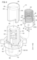
- FIG. 4 is an exploded perspective view of the puncture device shown in FIG. 3.
- FIG. 5 is a sectional view of the leading end of the housing taken along line VV in FIG. 2.
- FIG. FIG. 6 is a cross-sectional view taken along line VI-VI in FIG.
- FIG. 7 is a partially cross-sectional perspective view of the puncture device shown in FIG. 4.
- FIG. 8 is an overall front view of the puncture device shown in FIG. 7.
- FIG. 7 is a partially omitted perspective view of a liquid drug administration device including a puncturing device according to an embodiment of the present invention.
- FIG. 2 is an enlarged plan view of the vicinity of the
- FIG. 9 is a cross-sectional view of the housing of the liquid drug administration device shown in FIG. 3 in contact with the patient's skin.
- FIG. 10 is a partially sectional perspective view of the puncturing mechanism during puncturing.
- FIG. 11 is a cross-sectional plan view of the abutment member of FIG. 10 viewed from above.
- FIG. 12 is a cross-sectional view showing the state of puncturing with a puncturing needle.
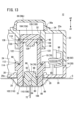
- FIG. 13 is a cross-sectional view showing a state in which the skin is separated from the housing during puncturing by the puncturing device shown in FIG. 12.
- the puncture device 10 is used as a drug solution administration device 12 that can administer a drug solution M.
- the drug solution administration device 12 is used, for example, to contact the patient's skin S (see FIG. 9) and administer the drug solution M subcutaneously to the patient.
- the drug solution administration device 12 includes a housing 14, a prefilled syringe 16 that stores a drug solution M, a moving mechanism 18 that delivers the drug solution M in the prefilled syringe 16, and a patient's skin S (see FIG. 9). ).
- the housing 14 serves as a casing for the liquid drug administration device 12 and a casing for the puncture device 10. That is, the liquid drug administration device 12 and the puncture device 10 share the housing 14.
- the housing 14 has a housing main body 20 and a housing cover 22.
- the housing body 20 is placed on the patient's skin S, and the housing cover 22 is placed on the opposite side of the skin S with the housing body 20 interposed therebetween. (See Figure 9).
- the housing body 20 and the housing cover 22 overlap in the thickness direction of the housing 14 (arrow A1, A2 direction).
- the direction of arrow A1 is the direction toward the skin S of the patient when the drug solution administration device 12 is installed on the patient's skin S.
- the direction of arrow A2 is the direction in which the liquid drug administration device 12 moves away from the skin S of the patient when it is installed on the skin S.
- the direction from the housing cover 22 to the housing body 20 (direction of arrow A1) will be referred to as downward, and the direction from housing body 20 to housing cover 22 (direction of arrow A2) will be referred to as upward.
- the housing 14 has a rectangular shape that is elongated in the longitudinal direction (direction of arrow B).
- the housing cover 22 covers the upper part of the housing body 20.
- the housing body 20 and the housing cover 22 are separable in the vertical direction (directions of arrows A1 and A2 in FIG. 1).
- the housing 14 has a space 24 surrounded by the housing body 20 and the housing cover 22, and the prefilled syringe 16, the moving mechanism 18, and the puncture device 10 are accommodated in the space 24 of the housing 14.
- the bottom wall 20a of the housing body 20 has a contact surface 26 that comes into contact with the patient's skin S.
- the housing 14 has an adhesive material 25 fixed to the bottom wall 20a of the housing body 20, and one surface of the adhesive material 25 serves as a contact surface 26.
- the contact surface 26 is flat along the longitudinal direction of the housing 14 (direction of arrow B in FIG. 2) and the width direction (direction of arrow C in FIG. 2) perpendicular to the longitudinal direction.
- the bottom wall 20a has a first hole 28.
- the first hole portion 28 is arranged at the distal end portion of the housing body 20 along the longitudinal direction. The first hole 28 passes through the bottom wall 20a and communicates the outside of the housing body 20 with the space 24.
- the bottom wall 20a of the housing body 20 has a stopper portion 30.
- the stopper portion 30 protrudes from the bottom wall 20a toward the housing cover 22 and is formed in an annular shape surrounding the first hole portion 28. That is, the stopper portion 30 is arranged on the outer periphery of the first hole portion 28 .
- the upper wall 22a of the housing cover 22 is formed parallel to the bottom wall 20a of the housing body 20.
- the upper wall 22a of the housing cover 22 has a second hole 32.
- a second hole 32 is arranged at the tip of the housing cover 22.
- the first hole 28 and the second hole 32 face each other.
- the upper wall 22a is provided with an annular protrusion 34 surrounding the second hole 32.
- the annular convex portion 34 protrudes upward (in the direction of arrow A2) from the upper wall 22a.
- the annular convex portion 34 is spaced apart from the second hole portion 32 toward the outside in the radial direction.
- An elastically deformable cover member 36 is arranged on the upper wall 22a of the housing cover 22.
- the cover member 36 is cap-shaped.
- the cover member 36 is arranged inside the annular protrusion 34 .
- the cover member 36 has an outer edge portion 36a and a covering portion 36b disposed inside the outer edge portion 36a.
- the outer edge portion 36a is adjacent to the inner peripheral surface of the annular convex portion 34 and abuts on the upper wall 22a of the housing cover 22.
- the covering portion 36b is offset in the axial direction (arrow A2 direction) with respect to the outer edge portion 36a, and faces the second hole portion 32.
- the covering portion 36b is disposed apart from the upper wall 22a of the housing cover 22 upwardly (in the direction of arrow A2).
- the covering portion 36b protrudes upward (in the direction of arrow A2) with respect to the annular convex portion 34.
- the second hole 32 is covered by the cover member 36.
- the upper wall 22a of the housing cover 22 has a support portion 38.
- the support portion 38 has a cylindrical shape that protrudes from the upper wall 22 a toward the housing body 20 and surrounds the second hole 32 .
- the second hole 32 penetrates from the upper wall 22a to the lower end of the support section 38.
- the inner circumferential surface of the support portion 38 has a housing side receiving portion 40 that is recessed radially outward.
- the housing side receiving portion 40 is a step formed from the lower end of the supporting portion 38 toward the upper wall 22a of the housing cover 22.
- the prefilled syringe 16 is housed inside the housing 14 and arranged along the longitudinal direction of the housing 14 (direction of arrow B).
- Prefilled syringe 16 has a barrel 42, a gasket 44, and a rod 46.
- the barrel 42 has a cylindrical shape with an open base end extending in the axial direction.
- the tip of the barrel 42 has a nozzle 48 that projects toward the tip.
- a gasket 44 is movably housed inside the barrel 42 .
- Gasket 44 is formed from a resilient material and is inserted into the interior of barrel 42 in a fluid-tight manner. Between the tip of the barrel 42 and the gasket 44, there is a chamber 50 filled with a chemical solution M.
- the rod 46 is formed into a cylindrical shape.
- the distal end of the rod 46 is inserted into the barrel 42 and connected to the proximal end of the gasket 44 .
- a proximal end of rod 46 is located outside barrel 42 .
- the rod 46 is arranged to be movable relative to the barrel 42 in the axial direction (distal direction, proximal direction, direction of arrow B).
- the moving mechanism 18 includes a motor 52, a gear section 54, and a shaft 56.
- the motor 52 is arranged in parallel with the prefilled syringe 16.
- Motor 52 is electrically connected to power supply section 58 .
- the power supply section 58 is arranged toward the tip of the motor 52.
- the power supply section 58 can supply power to the motor 52. Electric power is supplied from the power supply unit 58 to the motor 52, and a drive shaft (not shown) of the motor 52 is rotationally driven by the electric power. Drive control of the motor 52 is performed by a control section (not shown).
- the gear portion 54 is arranged toward the proximal end of the motor 52.
- the gear section 54 includes a drive gear 60 connected to the drive shaft, a driven gear 62 connected to the shaft 56, and an intermediate gear 64 meshed with the drive gear 60 and the driven gear 62.
- Intermediate gear 64 is arranged between drive gear 60 and driven gear 62.
- the driving gear 60, the driven gear 62, and the intermediate gear 64 are arranged in parallel in the width direction of the housing 14 (in the direction of arrow C).
- the drive gear 60 rotates together with the drive shaft of the motor 52.
- the driving gear 60 rotates, the intermediate gear 64 and the driven gear 62 rotate, thereby rotating the shaft 56.
- the shaft 56 extends along the axial direction and is inserted into the rod 46. Inside the rod 46, the outer peripheral surface of the shaft 56 and the inner peripheral surface of the rod 46 are screwed together.
- the shaft 56 is housed in the barrel 42 of the prefilled syringe 16 along with the rod 46 .
- a driven gear 62 is connected to the base end of the shaft 56.
- the puncturing device 10 is arranged at the distal end of the housing 14. As shown in FIG. 3, the lancing device 10 faces the first and second holes 28, 32.
- the puncturing device 10 includes a needle member 66, an abutting member 68, and a puncturing mechanism 70 that urges the needle member 66 toward the patient's skin S.
- the needle member 66 includes a puncture needle 72 and a needle hub 74 that holds the puncture needle 72.
- Puncture needle 72 is a hollow needle.
- the tip of the puncture needle 72 is capable of puncturing the patient's skin S.
- the proximal end of puncture needle 72 is held at the axial center of needle hub 74 .
- the needle hub 74 has a hub body 76.
- the hub body 76 When viewed in the axial direction of the needle hub 74, the hub body 76 has a circular shape.
- the hub body 76 has a large diameter portion 80 and a small diameter portion 82.
- the large diameter portion 80 is disposed toward the tip of the hub body 76 (in the direction of arrow A1).
- the tip of the hub body 76 (large diameter portion 80) has a hub surface 84.
- Hub surface 84 is a flat surface perpendicular to the axis of needle hub 74 .
- the proximal end of the puncture needle 72 is held at the axial center of the hub surface 84 .
- the hub surface 84 is the surface that comes into contact with the skin S (see FIG. 12).
- the small diameter portion 82 is arranged in the proximal direction (arrow A2 direction) of the large diameter portion 80.
- the diameter of the small diameter portion 82 is smaller than the diameter of the large diameter portion 80.
- the boundary between the small diameter portion 82 and the large diameter portion 80 has an annular hub side receiving portion 86 extending in the radial direction.
- the large diameter portion 80 of the hub body 76 has a communication path 88.
- the distal end of the communication path 88 extends along the axial center of the hub body 76 and opens into the hub surface 84 .
- the tip of the communication path 88 communicates with the inside of the puncture needle 72 .
- the base end of the communication passage 88 extends radially outward and opens at the outer circumferential surface of the large diameter portion 80 .
- the outer peripheral surface of the large diameter portion 80 has a connection hole 90 (see FIG. 4), and the connection hole 90 and the base end of the communication path 88 communicate with each other.
- connection hole 90 of the needle hub 74 and the prefilled syringe 16 are connected by an elastically deformable tube 92.
- the tube 92 is a tubular body and is arranged at the tip of the housing 14 (see FIG. 2).
- the tube 92 has flexibility and is capable of feeding the medical solution M from the prefilled syringe 16 to the needle member 66.
- the drug solution M is supplied from the prefilled syringe 16 to the communication path 88 (see FIG. 3) of the needle member 66 through the tube 92, and is sent from the communication path 88 to the puncture needle 72.
- the tube 92 includes a helical portion 94 wound in a spiral, a first extending portion 96 extending from one end of the spiral portion 94, and a second extending portion 98 extending from the other end of the spiral portion 94. has.
- the spiral portion 94 has a substantially circular shape and is wound a plurality of times along the vertical direction (direction of arrows A1 and A2).
- the first extending portion 96 extends substantially linearly along the width direction of the housing 14.
- the end of the first extension 96 is connected to the nozzle 48 of the prefilled syringe 16 .
- the second extending portion 98 extends along the longitudinal direction of the housing 14 .
- the end of second extension 98 is connected to connection hole 90 of needle hub 74.
- the spiral portion 94 of the tube 92 is accommodated inside the housing 14 in a vertically bent state.
- the second extending portion 98 moves together with the needle member 66, so that the spiral portion 94 of the tube 92 deforms elastically.
- the needle hub 74 further includes a pair of guided portions 78 disposed on the radially outer side of the hub body 76.
- the tip of the guided portion 78 is connected to the outer peripheral surface of the large diameter portion 80 .
- the pair of guided portions 78 face the outer circumferential surface of the small diameter portion 82 and are spaced apart from the outer circumferential surface of the small diameter portion 82 in the radial direction.
- One guided portion 78 and the other guided portion 78 are arranged symmetrically with respect to the axial center of the hub body 76.
- Each guided portion 78 has a locking portion 100.
- the locking portion 100 is arranged at the tip of the guided portion 78 .
- the locking portion 100 has a flat shape perpendicular to the axial direction of the needle hub 74.
- the guided portion 78 has an arcuate cross-sectional shape.
- the contact member 68 is provided movably in the housing 14 along the thickness direction of the housing 14 (directions of arrows A1 and A2).
- the abutment member 68 is arranged in the first hole 28 of the housing body 20.
- the abutting member 68 includes a cylindrical portion 102 and a gate portion 104 protruding from the cylindrical portion 102 in the proximal direction (arrow A2 direction).
- the cylindrical portion 102 is arranged at the tip of the abutment member 68.
- the distal end of the cylindrical portion 102 has a contact surface 106 that can come into contact with the patient's skin S (see FIG. 9).
- the contact surface 106 is a flat surface perpendicular to the axis of the contact member 68.
- the cylindrical portion 102 has an accommodation space 108 in which the needle member 66 is movably accommodated.
- the needle member 66 is movable relative to the abutment member 68 in the axial direction (directions of arrows A1 and A2) through the accommodation space 108.
- the accommodation space 108 has an opening 110 that opens at the tip (abutment surface 106) of the cylindrical portion 102. Puncture needle 72 can protrude from abutment surface 106 through opening 110.
- the base end of the cylindrical portion 102 has a flange portion 112 that expands radially outward.
- the flange portion 112 has an annular shape surrounding the accommodation space 108.
- the flange portion 112 has an annular spring receiving portion 114 extending radially inward from the inner peripheral surface of the flange portion 112 .
- the spring receiving portion 114 is arranged radially outward of the accommodation space 108.
- the contact member 68 has an engaging portion 115.
- the engaging portion 115 is a flat surface perpendicular to the axial direction of the abutment member 68. As shown in FIG. 7, in the initial state of the puncture device 10, the locking portion 100 of the needle hub 74 contacts the engaging portion 115 of the abutment member 68. This prevents the needle hub 74 from moving in the puncturing direction (the distal end direction, the direction of arrow A1) with respect to the contact member 68.
- a follow-up biasing member 116 is disposed inside the housing 14 between the cylindrical portion 102 of the abutment member 68 and the support portion 38 of the housing 14.
- the follow-up biasing member 116 is a spring member made of a coil spring.
- the follow-up biasing member 116 is arranged between the housing side receiving portion 40 of the support portion 38 and the spring receiving portion 114 of the cylindrical portion 102.
- the small diameter portion 82 of the hub body 76 is inserted into one end of the follow-up biasing member 116 .
- a convex portion 126, which will be described later, of the contact member 68 is inserted into the other end of the follow-up biasing member 116.
- the biasing force of the follow-up biasing member 116 is biased against the abutting member 68 .
- the contact member 68 is urged in the distal direction (puncture direction, arrow A1 direction) by the urging force of the follow-up urging member 116. That is, the follow-up biasing member 116 biases the contact member 68 toward the patient's skin S.
- the flange portion 112 of the contact member 68 contacts the stopper portion 30.
- the flange portion 112 of the abutting member 68 abuts against the stopper portion 30 of the housing 14, thereby preventing the abutting member 68 from coming off through the first hole 28.
- the contact member 68 has a protrusion 118 that projects from the contact surface 26 of the housing 14 when the contact surface 106 of the contact member 68 is not in contact with the skin S.
- the protrusion 118 protrudes to the outside of the housing 14 through the first hole 28 of the housing body 20.
- the contact surface 106 of the contact member 68 is pressed by the skin S, so that the protrusion 118 is accommodated inside the housing 14 through the first hole 28. (See Figure 9).
- the cylindrical portion 102 has a pair of guide grooves 120 that can guide the needle member 66 in the axial direction.
- the base end of the guide groove 120 is arranged at a position adjacent to the engaging part 115 in the circumferential direction of the cylindrical part 102.
- the guide groove 120 is recessed radially outward from the inner circumferential surface of the cylindrical portion 102 and faces the accommodation space 108 .
- a guided portion 78 of the needle member 66 can be inserted into the guide groove 120 .
- Each guide groove 120 extends along the axial direction of the contact member 68 (arrow A1, A2 direction).
- the gate portion 104 extends from the proximal end of the cylindrical portion 102 in the proximal direction (arrow A2 direction).
- the gate portion 104 includes a pair of pillar portions 122 and a bridge portion 124 that connects the base ends of the pillar portions 122.
- the pair of pillar portions 122 extend along the axial direction from the cylindrical portion 102 toward the proximal end, and are arranged symmetrically with respect to the axial center of the cylindrical portion 102 .
- the bridge portion 124 is perpendicular to the axial direction of the contact member 68 and connects the base end of one column portion 122 and the base end of the other column portion 122.
- the bridge portion 124 has a convex portion 126 in the center thereof that protrudes toward the cylindrical portion 102 . In the axial direction of the abutment member 68, the bridge portion 124 and the needle member 66 face each other (see FIG. 3).
- the puncturing mechanism 70 causes the needle member 66 to protrude from the abutting surface 106 of the abutting member 68 in response to an operation by a user (for example, a patient or a medical worker).
- the puncture mechanism 70 includes a pusher 128 provided with a pair of first inclined parts 132, a puncturing biasing member 130 (described later), and a needle hub 74 provided with a pusher 128 that contacts the first inclined parts 132.
- a pair of second inclined portions 134 that are in contact with each other are provided.
- the pusher 128 is disposed so as to be movable in the puncturing direction of the puncturing needle 72 (axial direction, arrow A1 direction) with respect to the housing 14.
- Pusher 128 is arranged in the proximal direction of abutment member 68 (arrow A2 direction).
- the pusher 128 has a cylindrical shape with a bottom.
- the gate portion 104 of the abutting member 68 is inserted into the pusher 128 .
- the top of the pusher 128 has a pressing portion 136 . In the initial state of the puncturing device 10, the pressing portion 136 is disposed within the second hole portion 32 of the housing cover 22.
- the outer circumferential surface of the pusher 128 has a pair of slit grooves 138 arranged symmetrically across the axial center of the pusher 128.
- the slit groove 138 extends along the axial direction from the distal end of the pusher 128 toward the proximal end.
- the slit groove 138 penetrates the pusher 128 in the radial direction.
- the column portions 122 of the abutting member 68 are inserted into the slit grooves 138, respectively.
- the base end of the slit groove 138 and the base end of the column portion 122 of the abutting member 68 are spaced apart in the axial direction.
- the pusher 128 and the contact member 68 can move relative to each other only along the axial direction (directions of arrows A1 and A2). That is, the pusher 128 and the contact member 68 are prevented from rotating relative to each other about the axes of the pusher 128 and the contact member 68.
- the puncture biasing member 130 is a spring member made of a coil spring.
- the puncturing biasing member 130 is arranged between the bridge portion 124 (see FIG. 3) of the abutment member 68 and the hub-side receiving portion 86 of the needle hub 74.
- the biasing force of the puncturing biasing member 130 is biased against the needle hub 74 .
- the puncture biasing member 130 biases the needle member 66 toward the patient's skin S. By urging the needle member 66 toward the patient's skin S by the puncturing urging member 130, the needle member 66 can move relative to the contact member 68 in the puncturing direction (arrow A1 direction).
- the pair of first inclined parts 132 are arranged at the tip of the pusher 128.
- the first inclined portion 132 is inclined with respect to the axial direction of the pusher 128.
- the first inclined portion 132 is inclined with respect to the puncturing direction of the puncturing needle 72 (arrow A1 direction).
- the first inclined portion 132 is inclined so as to extend clockwise when the pusher 128 is viewed from the proximal end toward the distal end toward the distal end direction (arrow A1 direction).
- the second inclined portion 134 is arranged at each guided portion 78 in the needle hub 74.
- the second inclined portion 134 is arranged at the base end of the guided portion 78 .
- the second inclined portion 134 can be brought into contact with the first inclined portion 132 of the pusher 128 .
- the second inclined portion 134 is inclined with respect to the puncturing direction of the needle member 66 (arrow A1 direction). That is, the second inclined portion 134 is inclined so as to extend clockwise when the needle member 66 is viewed from the proximal end toward the distal end toward the distal end direction (arrow A1 direction).
- the second inclined part 134 is inclined in the same direction as the first inclined part 132. Therefore, in the initial state of the puncturing device 10 shown in FIG. 7, the first inclined portion 132 and the second inclined portion 134 are in surface contact.
- the needle member 66 and pusher 128 move with respect to the housing 14 together with the abutment member 68. Due to the biasing force of the puncturing biasing member 130, the mutual positional relationship between the contact member 68 and the needle member 66 does not change. The mutual positional relationship between the contact member 68 and the pusher 128 also does not change.
- the spiral portion 94 of the tube 92 is elastically deformed so as to contract upward in the axial direction.
- the pusher 128 As the abutment member 68 moves, the pusher 128 is pushed up by the needle member 66, and the pressing portion 136 of the pusher 128 is housed inside the cover member 36 through the second hole 32. Since the pressing part 136 protrudes upward (in the direction of arrow A2) from the upper wall 22a of the housing cover 22, the user can direct the pressing part 136 in the puncturing direction (in the direction of arrow A1) through the covering part 36b of the cover member 36. It becomes possible to press.
- the user presses the pressing part 136 of the pusher 128 through the cover member 36, and pushes the pressing part 136 into the inside of the housing 14.
- the pusher 128 moves along the support portion 38 in the puncturing direction (arrow A1 direction), and the first inclined portion 132 presses the second inclined portion 134 in the puncturing direction.
- the guided part 78 having the second inclined part 134 is prevented from moving downward as the locking part 100 comes into contact with the engaging part 115.
- the position of the needle member 66 in the rotational direction relative to the abutment member 68 in the initial state shown in FIG. 7 is referred to as a "first position.”
- the pair of inclined parts The guided portion 78 receives force in a counterclockwise direction.
- the needle hub 74 begins to rotate counterclockwise from the first position about the axis of the needle hub 74 without moving in the puncturing direction.
- the needle hub 74 rotates and the pair of guided parts 78 reach the second position facing the base end of the guide groove 120, and the locking part 100 is released from the engaging part 115. Then, the needle hub 74 moves in the puncturing direction (arrow A1 direction) by the biasing force of the puncturing biasing member 130. At this time, the guided portion 78 is inserted into the guide groove 120, the guided portion 78 is guided along the guide groove 120 in the puncturing direction, and the needle hub 74 moves. The base end of the slit groove 138 of the pusher 128 contacts the base end of the column 122 of the contact member 68, and the pusher 128 is held in the puncturing direction by the contact member 68 (see FIG. 10).
- the needle hub 74 moves in the puncturing direction (arrow A1 direction) with respect to the contact member 68, the hub surface 84 comes into contact with the skin S, and the puncturing needle 72 moves into the patient's skin. Punctured by S.
- the tube 92 is elastically deformed downward.
- FIG. 13 shows a state in which the contact surface 26 of the housing 14 is in contact with the patient's skin S and the skin S is punctured by the puncture needle 72, and when the patient's body movement or the like occurs, the contact member 68 and the needle member 66 and the contact surface 26 of the housing 14 are shown separated in the puncturing direction of the needle member 66 (arrow A1 direction).
- the contact member 68 urged by the urging force of the follow-up urging member 116 moves the contact surface 106 against the facing portion S1. relative to the housing 14 so as to maintain contact with the housing 14. Thereby, the contact surface 106 and the facing portion S1 are not separated from each other in the puncturing direction.
- the needle member 66 moves together with the abutting member 68, and the puncturing of the skin S (opposing portion S1) by the puncturing needle 72 is maintained.
- the contact member 68 having the contact surface 106 that contacts the patient's skin S is movably provided in the housing 14, and the needle member 66 having the puncture needle 72 is movably provided in the housing 14. It is provided so as to be movable relative to the contact member 68. Therefore, with the contact surface 26 of the housing 14 in contact with the skin S, the relative position of the facing portion S1 of the skin S facing the contact surface 106 and the contact surface 26 of the housing 14 may change due to the patient's body movement or the like. Even when the change occurs, the abutment member 68 moves relative to the housing 14 so as to follow the facing portion S1 of the skin S, so that the puncture needle 72 of the needle member 66 is prevented from coming off from the skin S.
- a follow-up urging member 116 capable of urging the contact member 68 toward the patient's skin S is provided inside the housing 14, so that the follow-up urging member 116 makes contact with the skin S (facing portion S1). Since the contact state of the contact surface 106 of the member 68 is maintained, the needle member 66 (puncture needle 72) is reliably prevented from coming off.
- the protrusion 118 of the contact member 68 protrudes from the contact surface 26 of the housing 14;
- the contact surface 106 of the contact member 68 can be brought into reliable contact with the skin S.
- the contact member 68 is pushed by the skin S and the protrusion 118 is housed in the space 24 of the housing 14. Good contact between the contact surfaces 26 can be achieved.
- the puncture biasing member 130 By providing a puncture biasing member 130 capable of biasing the needle member 66 toward the patient's skin S inside the housing 14, the puncture biasing member 130 pushes the puncture needle 72 of the needle member 66 into contact with the abutting member. By protruding from the contact surface 106 of 68, the skin S can be reliably punctured.
- a tube 92 for feeding the drug solution M to the needle member 66 and the puncture needle 72 is connected to the needle hub 74 of the needle member 66, and the tube 92 is flexible and extends from the housing 14 in a bent state. It is accommodated within the space 24. Thereby, when the needle member 66 moves in the axial direction with respect to the housing 14, the tube 92 is elastically deformed, so that the tube 92 can suitably follow the needle member 66.
- the lancing device of the above embodiment includes a housing (14) having a contact surface (26) that contacts the skin (S) of a living body; a contact member (68) having a contact surface (106) in contact with the skin, movably provided in the housing, and capable of protruding from the contact surface; a needle member (66) having a puncture needle (72), movable relative to the contact member, and capable of protruding the puncture needle toward the skin from the contact surface; Equipped with Contact between the contact surface and the skin when the relative position between the housing and the portion (S1) of the skin that faces the contact surface changes while the housing is in contact with the skin.
- the abutment member moves relative to the housing so as to maintain the following.
- the puncture device includes a follow-up biasing member (116) that is provided inside the housing and biases the contact member toward the skin.
- the abutment member has a protrusion (118) that protrudes from the contact surface of the housing when the abutment surface of the abutment member is not in contact with the skin; When the contact surface of the housing contacts the skin, the contact member is pressed by the skin, so that the protrusion is housed inside the housing.
- the puncturing device includes a puncturing biasing member (130) that is provided inside the housing and biases the needle member toward the skin.
- the pricking device includes a pricking mechanism (70) that causes the needle member to protrude toward the skin with respect to the contact surface of the contact member,
- the puncturing mechanism includes a first inclined portion (132) that is inclined with respect to the puncturing direction of the puncturing needle, and a pusher (128) that is movable in the puncturing direction with respect to the housing; the puncturing biasing member; a second inclined part (134) provided on the needle member and inclined with respect to the puncturing direction and abutted by the first inclined part; Equipped with As the pusher moves in the puncturing direction, the needle member moves from the first position to the second position about the axis along the puncturing direction via the first inclined part and the second inclined part. rotate, When the needle member reaches the second position, it moves in the puncturing direction by the urging force of the puncturing urging member.
- the needle member includes a needle hub (74) that holds the puncture needle,
- the puncturing biasing member is disposed between the abutting member and the needle hub.
- the drug solution administration device includes a puncture device, a prefilled syringe (16) filled with a medical solution, connected to the needle member of the puncture device, and configured to deliver the medical solution to the puncture needle; Equipped with
Landscapes
- Health & Medical Sciences (AREA)
- Vascular Medicine (AREA)
- Engineering & Computer Science (AREA)
- Anesthesiology (AREA)
- Biomedical Technology (AREA)
- Heart & Thoracic Surgery (AREA)
- Hematology (AREA)
- Life Sciences & Earth Sciences (AREA)
- Animal Behavior & Ethology (AREA)
- General Health & Medical Sciences (AREA)
- Public Health (AREA)
- Veterinary Medicine (AREA)
- Dermatology (AREA)
- Infusion, Injection, And Reservoir Apparatuses (AREA)
Priority Applications (3)
| Application Number | Priority Date | Filing Date | Title |
|---|---|---|---|
| JP2024528330A JPWO2023243201A1 (https=) | 2022-06-17 | 2023-04-12 | |
| EP23823504.8A EP4501374A4 (en) | 2022-06-17 | 2023-04-12 | PUNCTURE DEVICE AND MEDICINAL SOLUTION DELIVERY DEVICE EQUIPPED WITH PUNCTURE DEVICE |
| US18/966,669 US20250090768A1 (en) | 2022-06-17 | 2024-12-03 | Puncture device and medicinal solution administering device equipped with puncture device |
Applications Claiming Priority (2)
| Application Number | Priority Date | Filing Date | Title |
|---|---|---|---|
| JP2022-098085 | 2022-06-17 | ||
| JP2022098085 | 2022-06-17 |
Related Child Applications (1)
| Application Number | Title | Priority Date | Filing Date |
|---|---|---|---|
| US18/966,669 Continuation US20250090768A1 (en) | 2022-06-17 | 2024-12-03 | Puncture device and medicinal solution administering device equipped with puncture device |
Publications (1)
| Publication Number | Publication Date |
|---|---|
| WO2023243201A1 true WO2023243201A1 (ja) | 2023-12-21 |
Family
ID=89190919
Family Applications (1)
| Application Number | Title | Priority Date | Filing Date |
|---|---|---|---|
| PCT/JP2023/014831 Ceased WO2023243201A1 (ja) | 2022-06-17 | 2023-04-12 | 穿刺装置及び穿刺装置を備えた薬液投与装置 |
Country Status (4)
| Country | Link |
|---|---|
| US (1) | US20250090768A1 (https=) |
| EP (1) | EP4501374A4 (https=) |
| JP (1) | JPWO2023243201A1 (https=) |
| WO (1) | WO2023243201A1 (https=) |
Citations (5)
| Publication number | Priority date | Publication date | Assignee | Title |
|---|---|---|---|---|
| JP2004208726A (ja) | 2002-12-26 | 2004-07-29 | Nishitomo:Kk | 生体穿刺装置 |
| US20110098580A1 (en) * | 2009-10-28 | 2011-04-28 | Megan Mikhail | Method and System for Treating Hypotension |
| WO2019189434A1 (ja) * | 2018-03-30 | 2019-10-03 | テルモ株式会社 | 投与器具、および薬液投与システム |
| JP2021520890A (ja) * | 2018-04-11 | 2021-08-26 | サノフイSanofi | 薬物送達デバイス |
| JP2022527182A (ja) * | 2019-03-29 | 2022-05-31 | ベクトン・ディキンソン・アンド・カンパニー | 可動性スリーブを備える注入アセンブリ |
Family Cites Families (1)
| Publication number | Priority date | Publication date | Assignee | Title |
|---|---|---|---|---|
| CA2132277C (en) * | 1993-10-22 | 2005-05-10 | Giorgio Cirelli | Injection device |
-
2023
- 2023-04-12 JP JP2024528330A patent/JPWO2023243201A1/ja active Pending
- 2023-04-12 EP EP23823504.8A patent/EP4501374A4/en active Pending
- 2023-04-12 WO PCT/JP2023/014831 patent/WO2023243201A1/ja not_active Ceased
-
2024
- 2024-12-03 US US18/966,669 patent/US20250090768A1/en active Pending
Patent Citations (5)
| Publication number | Priority date | Publication date | Assignee | Title |
|---|---|---|---|---|
| JP2004208726A (ja) | 2002-12-26 | 2004-07-29 | Nishitomo:Kk | 生体穿刺装置 |
| US20110098580A1 (en) * | 2009-10-28 | 2011-04-28 | Megan Mikhail | Method and System for Treating Hypotension |
| WO2019189434A1 (ja) * | 2018-03-30 | 2019-10-03 | テルモ株式会社 | 投与器具、および薬液投与システム |
| JP2021520890A (ja) * | 2018-04-11 | 2021-08-26 | サノフイSanofi | 薬物送達デバイス |
| JP2022527182A (ja) * | 2019-03-29 | 2022-05-31 | ベクトン・ディキンソン・アンド・カンパニー | 可動性スリーブを備える注入アセンブリ |
Non-Patent Citations (1)
| Title |
|---|
| See also references of EP4501374A4 |
Also Published As
| Publication number | Publication date |
|---|---|
| EP4501374A1 (en) | 2025-02-05 |
| US20250090768A1 (en) | 2025-03-20 |
| EP4501374A4 (en) | 2025-06-25 |
| JPWO2023243201A1 (https=) | 2023-12-21 |
Similar Documents
| Publication | Publication Date | Title |
|---|---|---|
| TWI558430B (zh) | 藥物輸送裝置 | |
| JP5203931B2 (ja) | 強制ロックアウト機構及び注入速度制限機構を有する注入器装置 | |
| JP6100840B2 (ja) | 注射装置 | |
| EP3760253B1 (en) | Sterile fluid pathway connection to drug containers for drug delivery pumps | |
| CN104093436B (zh) | 自动注射装置 | |
| US20170014575A1 (en) | AutoInjector having Needle Shield Triggering | |
| JP2019500160A (ja) | 針シールド発動を有する自動注射器 | |
| KR102629148B1 (ko) | 온-바디 약물 전달 장치를 위한 활성화 메커니즘 | |
| KR20150048834A (ko) | 약물 전달 펌프를 위한 제어식 전달 구동 기구 | |
| US11097068B2 (en) | Safety needle with deformable cannula for injector pen | |
| WO2023243201A1 (ja) | 穿刺装置及び穿刺装置を備えた薬液投与装置 | |
| US12453815B2 (en) | Device for connecting a reservoir to a fluid pathway in a medicament delivery apparatus | |
| WO2024057600A1 (ja) | 薬液投与装置 | |
| JP6716542B2 (ja) | 注射針組立体および薬剤注射装置 | |
| WO2024070024A1 (ja) | 穿刺装置及び穿刺装置を備えた薬液投与装置 | |
| WO2026089961A1 (en) | Miniature auto injector and methods of making and using same | |
| RU2593984C1 (ru) | Устройство введения лекарственного средства, содержащее сигнальное средство обратной связи | |
| WO2026053511A1 (ja) | 薬液投与装置 | |
| CN104136055B (zh) | 药物输送帮浦用与药物容器连接的无菌液体沟道连接件 | |
| HK1191594B (en) | Sterile fluid pathway connection to drug containers for drug delivery pumps |
Legal Events
| Date | Code | Title | Description |
|---|---|---|---|
| 121 | Ep: the epo has been informed by wipo that ep was designated in this application |
Ref document number: 23823504 Country of ref document: EP Kind code of ref document: A1 |
|
| WWE | Wipo information: entry into national phase |
Ref document number: 2024528330 Country of ref document: JP |
|
| WWE | Wipo information: entry into national phase |
Ref document number: 2023823504 Country of ref document: EP |
|
| ENP | Entry into the national phase |
Ref document number: 2023823504 Country of ref document: EP Effective date: 20241031 |
|
| NENP | Non-entry into the national phase |
Ref country code: DE |