WO2023243183A1 - 車両制御装置および車両制御システム - Google Patents
車両制御装置および車両制御システム Download PDFInfo
- Publication number
- WO2023243183A1 WO2023243183A1 PCT/JP2023/013190 JP2023013190W WO2023243183A1 WO 2023243183 A1 WO2023243183 A1 WO 2023243183A1 JP 2023013190 W JP2023013190 W JP 2023013190W WO 2023243183 A1 WO2023243183 A1 WO 2023243183A1
- Authority
- WO
- WIPO (PCT)
- Prior art keywords
- vehicle
- information
- invisible area
- vehicle control
- sun
- Prior art date
- Legal status (The legal status is an assumption and is not a legal conclusion. Google has not performed a legal analysis and makes no representation as to the accuracy of the status listed.)
- Ceased
Links
Images



Classifications
-
- B—PERFORMING OPERATIONS; TRANSPORTING
- B60—VEHICLES IN GENERAL
- B60W—CONJOINT CONTROL OF VEHICLE SUB-UNITS OF DIFFERENT TYPE OR DIFFERENT FUNCTION; CONTROL SYSTEMS SPECIALLY ADAPTED FOR HYBRID VEHICLES; ROAD VEHICLE DRIVE CONTROL SYSTEMS FOR PURPOSES NOT RELATED TO THE CONTROL OF A PARTICULAR SUB-UNIT
- B60W60/00—Drive control systems specially adapted for autonomous road vehicles
- B60W60/001—Planning or execution of driving tasks
- B60W60/0015—Planning or execution of driving tasks specially adapted for safety
-
- G—PHYSICS
- G08—SIGNALLING
- G08G—TRAFFIC CONTROL SYSTEMS
- G08G1/00—Traffic control systems for road vehicles
- G08G1/09—Arrangements for giving variable traffic instructions
-
- G—PHYSICS
- G16—INFORMATION AND COMMUNICATION TECHNOLOGY [ICT] SPECIALLY ADAPTED FOR SPECIFIC APPLICATION FIELDS
- G16Y—INFORMATION AND COMMUNICATION TECHNOLOGY SPECIALLY ADAPTED FOR THE INTERNET OF THINGS [IoT]
- G16Y10/00—Economic sectors
- G16Y10/40—Transportation
-
- G—PHYSICS
- G16—INFORMATION AND COMMUNICATION TECHNOLOGY [ICT] SPECIALLY ADAPTED FOR SPECIFIC APPLICATION FIELDS
- G16Y—INFORMATION AND COMMUNICATION TECHNOLOGY SPECIALLY ADAPTED FOR THE INTERNET OF THINGS [IoT]
- G16Y20/00—Information sensed or collected by the things
- G16Y20/20—Information sensed or collected by the things relating to the thing itself
-
- G—PHYSICS
- G16—INFORMATION AND COMMUNICATION TECHNOLOGY [ICT] SPECIALLY ADAPTED FOR SPECIFIC APPLICATION FIELDS
- G16Y—INFORMATION AND COMMUNICATION TECHNOLOGY SPECIALLY ADAPTED FOR THE INTERNET OF THINGS [IoT]
- G16Y40/00—IoT characterised by the purpose of the information processing
- G16Y40/20—Analytics; Diagnosis
-
- B—PERFORMING OPERATIONS; TRANSPORTING
- B60—VEHICLES IN GENERAL
- B60W—CONJOINT CONTROL OF VEHICLE SUB-UNITS OF DIFFERENT TYPE OR DIFFERENT FUNCTION; CONTROL SYSTEMS SPECIALLY ADAPTED FOR HYBRID VEHICLES; ROAD VEHICLE DRIVE CONTROL SYSTEMS FOR PURPOSES NOT RELATED TO THE CONTROL OF A PARTICULAR SUB-UNIT
- B60W2420/00—Indexing codes relating to the type of sensors based on the principle of their operation
- B60W2420/40—Photo, light or radio wave sensitive means, e.g. infrared sensors
- B60W2420/403—Image sensing, e.g. optical camera
-
- B—PERFORMING OPERATIONS; TRANSPORTING
- B60—VEHICLES IN GENERAL
- B60W—CONJOINT CONTROL OF VEHICLE SUB-UNITS OF DIFFERENT TYPE OR DIFFERENT FUNCTION; CONTROL SYSTEMS SPECIALLY ADAPTED FOR HYBRID VEHICLES; ROAD VEHICLE DRIVE CONTROL SYSTEMS FOR PURPOSES NOT RELATED TO THE CONTROL OF A PARTICULAR SUB-UNIT
- B60W2555/00—Input parameters relating to exterior conditions, not covered by groups B60W2552/00, B60W2554/00
- B60W2555/20—Ambient conditions, e.g. wind or rain
Definitions
- a vehicle control system installed in a vehicle that performs driving support and automatic driving recognizes the situation around the vehicle based on information obtained from sensor devices, and performs driving support and automatic driving based on the surrounding situation.
- peripheral situation recognition using a camera device which is one type of sensor device
- Vehicle control systems are required to avoid such dangerous situations in backlit environments. To ensure safety, vehicle control systems are required to avoid environments where performance limits occur, or to take measures to prevent problems even if performance limits occur.
- Patent Document 1 discloses a technique for searching for a route in which the angular difference between the forward camera photographing direction and the direction in which the sun is located remains outside a predetermined range.
- the predetermined range is a range of angular differences that are estimated to make it impossible to recognize the surrounding situation due to backlighting.
- Patent Document 1 ensures safety by avoiding dangerous areas where the camera photographing direction and the direction of the sun are within a predetermined range.
- all roads traveling westward in the evening are out of range, which greatly reduces the availability of the vehicle control system.
- Patent Document 2 discloses a technique that sets a dangerous area where it is difficult to recognize a traffic light due to backlighting, etc., and determines whether the line of sight from the camera to the traffic light is blocked by surrounding vehicles outside the dangerous area.
- Patent Document 2 mentions a dangerous area where traffic lights cannot be recognized, it does not disclose how to set the position of this dangerous area.
- the position of the sun changes from moment to moment, and the dangerous area due to backlight also changes from moment to moment.
- a vehicle control system or a vehicle control device included in the vehicle control system calculates position information of a visible object and the position of the sun at predetermined time information. Then, based on the calculated sun position information and the position information of the visible object, an area on the road where the visible object is difficult to see due to backlighting (hereinafter referred to as an invisible area) is calculated. Furthermore, safety is ensured by controlling vehicle travel or backlight protection devices based on the calculated invisible area. For example, the speed of the vehicle is adjusted so that the position of the vehicle at a timing when the object to be viewed must be visually recognized, such as when entering an intersection, is not within the invisible area. For example, if it is determined that the sun is on the right side of the visible object when viewed from the viewing subject within the invisible area, the sun visor is controlled so that it overlaps with the position of the sun when viewed from the viewing subject.
- the safety of a vehicle control system in a backlit environment is ensured by accurately calculating a dangerous area where it is difficult to see the target object due to backlighting at a predetermined time and with respect to the target object. while improving availability. Furthermore, the safety of the vehicle control system can be improved by taking countermeasures based on information about the dangerous area.
- FIG. 1 is a functional block diagram showing the configuration of a vehicle control system including a vehicle control device according to a first embodiment of the present invention.
- a specific example of a part of the processing flow of a vehicle control information generation unit (related to a backlight countermeasure device).
- a specific example of a part of the processing flow of the vehicle control information generation unit (related to vehicle stop position adjustment).
- FIG. 3 is a functional block diagram showing the configuration of a vehicle control system according to a third embodiment of the present invention.
- the vehicle control device 110 is an ECU (Electronic Control Unit).
- the vehicle control device 110 generates travel control information for driving support or automatic driving of the vehicle 102 based on various input information provided from the map information management device 111, the sensor device group 112, etc., and generates travel control information for backlight countermeasures. Control information for the device group 114 is generated. Then, the vehicle control device 110 outputs control information to the actuator group 113, the backlight countermeasure device group 114, and the like.
- the vehicle control device 110 includes a processing section 120 and a storage section 121.
- the processing unit 120 is configured to include, for example, a CPU (Central Processing Unit) that is a central processing unit. However, in addition to the CPU, it may be configured to include a GPU (Graphics Processing Unit), FPGA (Field-Programmable Gate Array), ASIC (Application Specific Integrated Circuit), etc., or it may be configured by any one of them. good.
- the storage unit 121 includes, for example, a storage device such as an HDD (Hard Disk Drive), a flash memory, or a ROM (Read Only Memory), and a memory such as a RAM (Random Access Memory).
- the storage unit 121 stores programs processed by the processing unit 120, data groups necessary for the processing, and the like.
- the storage unit 121 is also used as a main memory when the processing unit 120 executes a program, and is also used to temporarily store data necessary for calculations of the program.
- the map information management device 111 includes information regarding visible objects, and the visible objects are associated with various object information (traffic lights, landmarks, etc.) in digital road map data, for example. . Furthermore, the map information management device 111 outputs the current position of the specified vehicle 102, map data around it, route information, and visible object information to the vehicle control device 110 via the in-vehicle network.
- the sensor device group 112 is a collection of devices that detect the surrounding situation of the vehicle 102 and various states of the vehicle 102.
- the sensor device group 112 includes, for example, a camera device, millimeter wave radar, LiDAR, sonar, wheel odometry, and the like.
- the sensor device group 112 transmits sensing observation information around the vehicle 102 and information on environmental elements such as obstacles, road markings, signs, and signals identified based on the observation information to the vehicle control device 110 via the in-vehicle network.
- Output. "Obstacles" include, for example, other vehicles other than the vehicle 102, pedestrians, fallen objects on the road, road edges, and the like.
- the sensor device group 112 detects position information, traveling speed, steering angle, accelerator operation amount, brake operation amount, etc. of the vehicle 102, and outputs the detected information to the vehicle control device 110 via the in-vehicle network.
- the actuator group 113 is a device group that controls control elements such as steering, brakes, and accelerators that determine the movement of the vehicle.
- the actuator group 113 controls the movement of the vehicle based on operation information of the steering wheel, brake pedal, accelerator pedal, etc. by the driver and control command values output from the vehicle control device 110.
- the backlight countermeasure device group 114 is an in-vehicle device that blocks or reduces sunlight (direct sunlight) on the viewer in the vehicle within the specified invisible area.
- the backlight countermeasure device group 114 includes, for example, an electric lens hood for the sensor device group 112, an electric sun visor for the driver of the vehicle 102, and a light control glass device that changes the transmittance of sunlight.
- the processing unit 120 included in the vehicle control device 110 has the functions of a map information acquisition unit 130, a sun position calculation unit 131, an invisible area calculation unit 132, an invisible area output unit 133, a vehicle surrounding situation recognition unit 134, and a visual recognition unit 134. It includes a disabled area acquisition section 135, a vehicle control information generation section 136, and a vehicle control information output section 137.
- the processing unit 120 realizes these by executing a predetermined operation program stored in the storage unit 121.
- the map information acquisition unit 130 acquires information from the map information management device 111 via the in-vehicle network, and stores it in the map data group 141 and the visible object data group 142 of the storage unit 121.
- the sun position calculation unit 131 calculates the position of each visible object on the route of the vehicle 102 and the sun's position information at a predetermined time from the map data group 141 and the visible object data group 142.
- the predetermined time is, for example, when the vehicle 102 passes around the visible object based on the speed of the vehicle 102 that can be obtained from the sensor data group 144 and the distance on the route to the visible object that can be obtained from the map data group 141. This is the expected time.
- the time when the vehicle 102 is expected to pass around the visible object based on the distance on the route to the visible object and information on the legal maximum speed of the road on the route. be.
- it is the current time.
- the predetermined time may be expressed as a single time, or may be expressed as time information having a range of two values: a start time and an end time.
- the sun position calculated by the sun position calculation unit 131 calculates a single position information if the predetermined time is a single time, or calculates a single position information if the predetermined time is a single time; For example, it is expressed as the range of positions that the sun can take during that time.
- the invisible area output unit 133 outputs the information stored in the invisible area data group 143. As long as it is output within the same vehicle control device 110, it may be output as pointer information to the invisible area data group 143 instead of the invisible area information itself.
- the self-vehicle surrounding situation recognition unit 134 recognizes the situation of the driving road, other vehicles, etc. around the vehicle 102 based on the information of the map data group 141 and the sensor data group 144.
- the self-vehicle surrounding situation recognition unit 134 is realized by a known technology in driving support and automatic driving.
- the invisible area acquisition unit 135 acquires information about the invisible area from the invisible area output unit 133, and stores it in the invisible area data group 143 if necessary.
- the invisible area output unit 133 outputs pointer information for the invisible area data group 143, it is only necessary to hold the pointer information.
- the vehicle control information generation unit 136 first generates driving control information necessary for driving support and automatic driving based on the situation around the vehicle 102 recognized by the own vehicle surrounding situation recognition unit 134, and stores it in the driving control data group 145. do. Generation of this travel control information is realized using known technology in driving support and automatic driving.
- the vehicle control information generation unit 136 updates the travel control information included in the travel control data group 145 based on the situation around the vehicle 102, the map data group 141, and the invisible area data group 143. Specifically, based on the route information included in the map data group 141 and the travel control data group 145, it is determined whether the vehicle 102 passes through an invisible area. If it is determined that the vehicle will pass, travel control is considered to prevent the vehicle from falling into a dangerous situation in the invisible area, and the travel control data group 145 is updated. For example, when the vehicle 102 stops in an invisible area and must visually recognize an object at that time, the travel control data group 145 is updated so that the vehicle 102 stops in front of or on the other side of the invisible area. For example, when the vehicle 102 traveling at a predetermined speed needs to visually recognize a visible object within an invisible area, the travel control data group 145 is updated to accelerate or decelerate the speed of the vehicle 102.
- the vehicle control information generation unit 136 determines that the vehicle 102 passes through an invisible area, the vehicle control information generation unit 136 generates a backlight that allows the viewer to see the object by blocking or reducing backlight in the invisible area.
- Control information for controlling the countermeasure device group 114 may be generated.
- the vehicle control information generation unit 136 stores the generated control information in the backlight countermeasure device control data group 146.
- an electric sun visor may be installed so as to overlap the area on the right side of the visible object when viewed from the viewing subject. Generate information to control the movement.
- the vehicle control information output unit 137 outputs the travel control information included in the travel control data group 145 to the actuator group 113. Further, the vehicle control information output unit 137 outputs the control information included in the backlight countermeasure device control data group 146 to the backlight countermeasure device group 114. That is, the vehicle control information output unit 137 outputs information for operating the backlight countermeasure device group 114 as vehicle control information.
- the visible object data group 142 is a set of data related to visible objects output by the map information management device 111.
- the visible object data group 142 includes information such as the ID, position, size, direction, type, and corresponding road of the visible object, for example.
- the type is information indicating the type of the object to be visually recognized, and corresponds to, for example, a traffic light.
- the corresponding road is information about the road corresponding to the visible object. For example, if the object to be visually recognized is a traffic light, the traffic light in the straight direction at an intersection is visually recognized, and the traffic light in the orthogonal direction is not visually recognized. In this way, it includes information for associating objects in order to identify objects to be visually recognized depending on the road.
- the structure of the visible object data group 142 is not limited to that shown in FIG. 1 and the above-mentioned description.
- the visible object data group 142 may be included in the map data group 141.
- flag information indicating that the object is a visible object may be added to various object information such as a traffic light included in the map data group 141.
- the invisible area data group 143 is a set of data related to invisible areas.
- the invisible area data group 143 includes, for example, the ID of the invisible area, the ID of the corresponding visible object, and the position information of the vertices forming the invisible area.
- the information of the invisible area data group 143 is generated and stored by the invisible area calculation unit 132.
- the sensor data group 144 is a collection of data related to information detected by the sensor device group 112.
- the detection information includes, for example, information regarding environmental elements such as obstacles, road markings, signs, and traffic lights identified based on observation information sensed by the sensor device group 112, and the position, traveling speed, steering angle, and accelerator operation of the vehicle 102. This includes information such as the amount of brake operation and the amount of brake operation.
- the travel control data group 145 is a collection of data related to planning information for controlling the travel of the vehicle 102, and includes the planned trajectory of the vehicle 102, control command values to be output to the actuator group 113, and the like.
- the information of the travel control data group 145 is generated and stored by the vehicle control information generation section 136.
- the backlight countermeasure device control data group 146 is a set of data related to the control of the backlight countermeasure device group 114, and includes control command values to be output to the backlight countermeasure device group 114.
- the information of the backlight countermeasure device control data group 146 is generated and stored by the vehicle control information generation unit 136.
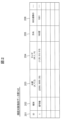
- FIG. 2 is a diagram illustrating an example of information regarding the visual recognition target object data group 142.
- Column 201 is an ID that uniquely identifies the object to be viewed.
- Column 202 is a value indicating the type of the object to be viewed.
- the values shown in column 202 include, for example, values corresponding to traffic lights, signs, electronic display boards, and the like.
- Columns 203, 204, and 205 are information indicating the position, size, and direction of the visible object, respectively.
- the column 203 includes, for example, horizontal position and vertical position information and altitude information in the map data group 141.
- the column 203 may be expressed in the same coordinate system as the coordinate system expressed in the map data group 141, or may be expressed in a different coordinate system that has a one-to-one correspondence with that coordinate system.
- Column 204 includes information on the width, depth, and height of the object to be viewed.
- the column 205 is expressed as an angle with respect to a predetermined direction or a predetermined coordinate axis in the map data group 141 as a reference.
- the column 206 is information that identifies the road to which the visible object is related, and the road ID stored in the map data group 141 is set.
- a plurality of columns 206 may be set assuming that the column 206 is related to a plurality of roads, or a lane ID may be set as a value for identifying a related lane.
- Information regarding the visible target object is not limited to the content shown in FIG. 2.
- a traffic light sub-type information that identifies a pedestrian traffic light, a traffic light with a right turn arrow, etc. may be included.
- information on the ID of each object included in the map data group 141 may be included.
- Information similar to 2 may be expressed.
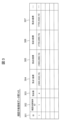
- FIG. 3 is a diagram showing an example of information regarding the invisible area data group 143.
- Column 301 is an ID for uniquely identifying the invisible area.
- Column 302 is set to any value present in column 201 of visible object data group 142, and associates the visible object with the invisible area.
- the ID of the various object information is here. Set.
- Column 303 is the number of vertices included in each invisible area.
- Columns 304 to 307 are position information of each vertex when the number of vertices is four.
- Columns 304 to 307 are composed of, for example, horizontal position information, vertical position information, and altitude information in the map data group 141.
- the columns 304 to 307 may be expressed in the same coordinate system as the coordinate system expressed in the map data group 141, or may be expressed in a different coordinate system that has a one-to-one correspondence with that coordinate system. good.
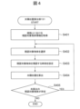
- FIG. 4 is a diagram showing a processing flow of the sun position calculation unit 131.
- the sun position calculation unit 131 refers to the map data group 141 and the visible object data group 142 and acquires all visible objects on the route of the vehicle 102 (step S401). For example, if the route information of the vehicle 102 is given as a list of road IDs, it may be obtained by searching the road ID list information and the column 206 of the visible object data group 142. Even if the route information is a list of lane IDs and the column 206 of the visible object data group 142 is the lane ID, the same search is possible.
- the position information of the road area is acquired from the list of road IDs and the map data group 141, and within a predetermined distance from the position. It may also be acquired by searching for visible objects that exist in .
- the sun position calculation unit 131 calculates the sun position based on this time information and the position information of the selected object to be viewed (step S404).
- This calculation method is realized using a known technique, and the calculated sun position is expressed, for example, in terms of elevation angle and azimuth.
- the expression of the sun position information calculated in step S404 differs depending on the expression of the time information in step S403. If the time information is expressed as a single time, the position of the sun corresponding to that time will be expressed as a single position information.
- time information is expressed as information having a width of a start time and an end time
- the position of the sun is also expressed as a range of sun positions that can take place between the start time and the end time.
- the sun position calculation unit 131 checks whether there is a visible target object that has not been subjected to the processes of steps S403 to S404, among the visible target objects obtained in step S401 (step S405). If the object exists (YES in step S405), the process returns to step S402 and another object to be viewed is selected. If it does not exist (NO in step S405), the process of the sun position calculation unit 131 ends.
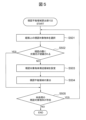
- the invisible area calculation unit 132 sets a visible target object peripheral area for the selected visible target object.
- the invisible area calculation unit 132 sets a visible target object surrounding area including the space around the selected visible target object for the spatial area occupied by the selected visible target object based on the position information of the selected visible target object, Calculate the invisible area from the sun's position information and the area around the visible object. Specifically, in consideration of backlighting, an area including the surrounding space of the selected visual recognition target object is set for the space occupied by the selected visual recognition target object. Details of the area around the visible object will be described below.
- the size of the area around the visible object may be calculated by multiplying the size of the selected visible object by a predetermined coefficient, or by adding a predetermined value to the size of the selected visible object. It may be calculated by Details of the area around the visible object will be described later using FIG. 6.
- step S505 the invisible area calculation unit 132 checks whether there is a visible target object that has not been processed in steps S502 to S504 yet. If the object exists (YES in step S505), the process returns to step S501 and another object to be viewed is selected. If it does not exist (NO in step S505), the process of the invisible area calculation unit 132 ends.
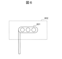
- FIG. 6 is a diagram showing a traffic light, which is an example of a visible object, and the corresponding surrounding area of the visible object.
- the visible object 601 is a traffic light, and information regarding its position and size is included in the visible object data group 142.
- the invisible area calculation unit 132 generates a visible target object peripheral area 602 for the visible target object 601.
- the size of the visible target object peripheral area 602 may be calculated by multiplying the size of the visible target object 601 by a predetermined coefficient, or may be calculated by adding a predetermined size. .
- the center of the visible target object 601 is configured to be the same as the center of the visible target object peripheral area 602.
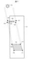
- FIG. 7 is a top view of a road 701 on which a visible object 601 is installed.
- a visible target object 601 and a corresponding visible target object peripheral area 602 are set.
- the sun 702 exists on the other side of the visible object 601.
- the position of the sun 702 (elevation angle ⁇ 1, azimuth ⁇ 2) is calculated by the sun position calculation unit 131.
- the invisible area calculation unit 132 calculates the invisible area 703 based on the visible object peripheral area 602 and the position information of the sun 702. An example of a method for calculating this invisible area 703 will be described below.
- the vertices of the visible target object peripheral area 602 are vertices 704, 705, 706, and 707 in a counterclockwise direction from the upper left.
- a line with an elevation angle ⁇ 1 and an azimuth ⁇ 2 is drawn from the vertex 704 toward the sun.
- This line is a line from the vertex 704 toward the sun.
- extend that line in the opposite direction calculate the point where it intersects with the surface of the road 701, and that point becomes the vertex 708. This is based on the position information (including altitude information) of any point on the road included in the map data group 141, the position information (including altitude information) and the size of the visible target object surrounding area 602 set in step S503.
- the invisible area 703 can be easily calculated. This is because the map data group 141 includes altitude information at each position on the road, and this is taken into consideration.
- an invisible area 703 corresponding to each position of the sun 702 within that position range is calculated. However, it can be easily calculated by overlapping the respective invisible areas 703.
- FIG. 7 illustrates a method for calculating the invisible area 703 on the surface of the road 701.
- a method of calculating the invisible area that takes into account the height information of the viewing subject will also be mentioned.
- the height information of the visual recognition subject is the eye level of the driver, and in the case of the sensor device group 112, it is the height information at which the sensor device group 112 is installed. These are expressed, for example, as heights from the tire contact surface of the vehicle 102.
- an invisible area 703 is calculated by calculating the point where the extension of a line drawn from the visible object peripheral area 602 in the direction of the sun intersects with the surface of the road 701.
- the invisible area is calculated by calculating the vertices 708 to 711 that intersect with the surface of the road 701 instead of the points that intersect with this surface. That is, the invisible area calculation unit 132 calculates the invisible area based on the height information of the position of the viewer who visually recognizes the object to be viewed in the vehicle.
- the invisible area 703 calculated using this method is an invisible area that corresponds to the height that the viewing subject views, and is a highly accurate area that takes into consideration the viewing subject's visibility.
- FIG. 8 is a diagram showing the entire processing flow of the vehicle control information generation section 136.
- step S801 the vehicle control information generation unit 136 uses the information in the map data group 141, the information on the vehicle 102 that can be obtained from the sensor device group 112, and the situation around the vehicle 102 recognized by the own vehicle surrounding situation recognition unit 134. Based on this, travel control information is generated and stored in the travel control data group 145.
- the process in step S801 is realized using known technology related to driving support and automatic driving.
- the vehicle control information generation unit 136 refers to the route information, the invisible area data group 143, and the travel control data group 145 included in the map data group 141, and determines the possibility that the vehicle 102 will pass through an invisible area. Determine if there is. For example, it may be determined whether an invisible area exists on the route of the vehicle 102 by referring to the travel control data group 145, or whether an invisible area exists on the route of the vehicle 102 by referring to route information. You can also determine whether it exists. If it is determined that there is a possibility of passing (YES in step S802), the process moves to step S803. If it is determined that there is no possibility of passing (NO in step S802), the processing of the vehicle control information generation unit 136 is ended.
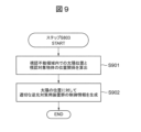
- FIG. 9 is a diagram showing a processing flow for controlling the backlight countermeasure device group 114 as an example of step S803. This process is performed in order to allow the viewing subject to see the object even in the invisible area by blocking sunlight that enters the viewing subject of the vehicle 102 with the backlight countermeasure device group 114.
- step S901 the vehicle control information generation unit 136 calculates the positional relationship between the sun and the visible object when the visual subject of the vehicle 102 views the object within the invisible area. For example, in the invisible area, a positional relationship is calculated such that the sun is on the right side of the visible object as viewed from the viewing subject.
- the vehicle When entering the invisible area, the vehicle initially exists above the visible object as seen from the viewing subject, but as the vehicle moves, it may change over time, such as moving from above the visible object to below the visible object. You can calculate it here.
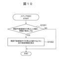
- step S1001 the vehicle control information generation unit 136 determines whether a problem may occur in which it is difficult to perform appropriate processing regarding the driving support and automatic driving provided by the vehicle control system 101 when the vehicle 102 is stopped within the invisible area.
- the visible object is a traffic light.
- Whether or not to consider this traffic light use case can be determined according to the information in column 202 of the visible object data group.
- a problem may occur, for example, when a stop line corresponding to a traffic light exists within an invisible area. This can be easily determined by utilizing the information in the map data group 141. In this case, if the vehicle 102 stops in the invisible area, the color of the traffic light becomes difficult to see due to backlight, making it difficult to judge when the vehicle 102 should start.
- the case where no problem occurs is, for example, the case where the stop line corresponding to the traffic light and the invisible area are separated by some distance. This can also be easily determined based on the information in the map data group 141. In this case, no problem may occur because the vehicle 102 may determine whether to start or not depending on the situation of surrounding vehicles on the road, without depending on the color of the traffic light.
- step S1001 If it is determined that a problem may occur (YES in step S1001), the process moves to step S1002. If it is determined that this does not occur (NO in step S1001), the process in step S803 ends.
- the vehicle control information generation unit 136 modifies the travel control information included in the travel control data group 145 so that the vehicle 102 does not stop within the invisible area. For example, if it is determined that the vehicle must stop within the invisible area, the travel control information is corrected so that the vehicle stops before the invisible area. Alternatively, if it is determined that the vehicle can be stopped on the other side of the invisible area when viewed from the vehicle 102, the travel control information is corrected so that the vehicle can be stopped on the other side of the invisible area. Alternatively, after confirming that the vehicle 102 does not need to stop in or around the invisible area, the travel control information is corrected so that the vehicle 102 passes through the invisible area. Then, the vehicle control information generation unit 136 ends the process of step S803.
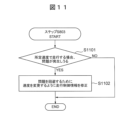
- FIG. 11 is a diagram showing a processing flow related to driving control of the vehicle 102 as an example of step S803. This process is performed in order to avoid problems caused by difficulty in visually recognizing objects to be viewed when the vehicle 102 travels at a predetermined speed by adjusting the speed of the vehicle 102.
- the vehicle control information generation unit 136 determines whether a problem may occur in which it is difficult for the vehicle control system 101 to perform appropriate processing regarding driving support and automatic driving when the vehicle 102 passes through an invisible area at a predetermined speed.
- the predetermined speed is the current speed of the vehicle 102 that can be obtained from the sensor device group 112, the legal maximum speed on the road that can be obtained from the map data group 141, or the surroundings of the vehicle 102 recognized by the own vehicle surrounding situation recognition unit 134. This is the speed assumed based on the traveling speed of the vehicle, etc. Further, the predetermined speed does not need to be uniquely determined, and the range of the predetermined speed may be determined using two pieces of information: the legal minimum speed and the legal maximum speed. In this case, in the following description, similar processing can be easily realized by repeating similar processing for each value within the range.
- the object to be visually recognized is a traffic light.
- a problem may occur, for example, when the position of the vehicle 102 at a predetermined speed overlaps with an invisible area at the time when it is determined whether to enter an intersection by visually checking the color of a traffic light. . This can be easily determined from the distance along the route from the invisible area to the traffic light, which can be obtained from the map data group 141 and the invisible area data group 143, and the predetermined speed. In this case, the backlight makes it difficult to see the color of the traffic light, making it difficult to judge whether the vehicle 102 should enter the intersection.
- a case in which no problem occurs is, for example, a case in which the position of the vehicle 102 at a predetermined speed does not overlap with an invisible area at the time when it is determined whether to enter an intersection by visually checking the color of a traffic light. It is. In this case, since the color of the traffic light can be recognized at the required timing, appropriate processing can be performed.
- the vehicle control information generation unit 136 modifies the travel control information included in the travel control data group 145 and adjusts the speed of the vehicle 102 in and around the invisible area. For example, the position of the vehicle 102 at the time when it is determined whether to enter an intersection by visually checking the color of the traffic light is on the other side of the invisible area (that is, on the side closer to the traffic light than the invisible area). The speed of vehicle 102 is reduced. Alternatively, the speed of the vehicle 102 is increased so that the position of the vehicle 102 at that timing is closer to the invisible area (that is, further away from the traffic light than the invisible area). Then, the vehicle control information generation unit 136 ends the process of step S803.
- the vehicle control device 110 calculates the invisible area corresponding to the visible target object, and provides information for controlling the actuator group 113 and the backlight countermeasure device group 114 based on the invisible area. Output. This makes it possible to improve the availability of driving support and autonomous driving in backlit environments while ensuring safety.
- the processing unit 1210 included in the server device 1202 has a server-side map information management unit 1221, a sun position calculation unit 131, an invisible area calculation unit 132, and an invisible area output unit 133 as its functions.
- the processing unit 1210 realizes these by executing a predetermined operation program stored in the storage unit 1211.
- the map information acquisition unit 130 acquires information regarding the map data group 141 and the visible object data group 142, and stores the information in the map data group 141 and the visible object data group 142 in the storage unit 121. do.
- the map information acquisition unit 130 may acquire the map information from the map information management device 111 as in the first embodiment, or may acquire it from the server-side map information management unit 1221 via the network 1203.
- the storage unit 121 included in the vehicle control device 110 includes a map data group 141, a visible object data group 142, an invisible area data group 143, a sensor data group 144, a travel control data group 145, and a backlight countermeasure device control data group. 146 are included. These data groups are the same as in the first embodiment.
Landscapes
- Engineering & Computer Science (AREA)
- Computing Systems (AREA)
- Automation & Control Theory (AREA)
- Human Computer Interaction (AREA)
- Transportation (AREA)
- Mechanical Engineering (AREA)
- Development Economics (AREA)
- Accounting & Taxation (AREA)
- Business, Economics & Management (AREA)
- Economics (AREA)
- General Business, Economics & Management (AREA)
- Operations Research (AREA)
- Physics & Mathematics (AREA)
- General Physics & Mathematics (AREA)
- Health & Medical Sciences (AREA)
- Biomedical Technology (AREA)
- General Health & Medical Sciences (AREA)
- Traffic Control Systems (AREA)
Abstract
Description
センサ装置の1つであるカメラ装置を活用した周辺状況認識では、逆光が原因で撮像画像の一部が白飛びすることにより車両の周辺の物体を認識できないといった性能限界がある。カメラ装置を活用して信号の色を認識する時にこの性能限界が発生すると、事故等の危険な状況に陥ってしまう。車両制御システムは、逆光環境下でのこのような危険な状況を回避することが求められる。安全性を担保するため、車両制御システムは性能限界が発生するような環境を回避するか、性能限界が発生しても問題ないように対策を行うことが求められる。
(システム構成)
図1は、本発明の第1の実施形態に関する車両制御装置110を含む車両制御システム101の構成を示す機能ブロック図である。車両制御システム101は車両102に搭載される。車両制御システム101は、車両102の周辺における走行道路や周辺車両等の状況を認識し、車両102の運転支援や走行制御を行うシステムである。車両制御システム101は、車両制御装置110、地図情報管理装置111、センサ装置群112、アクチュエータ群113、逆光対策用装置群114を含んで構成される。車両制御装置110、地図情報管理装置111、センサ装置群112、アクチュエータ群113、逆光対策用装置群114は車載ネットワークにより互いに接続される。
図2は、視認対象物体データ群142に関する情報の一例を示す図である。
図4~図7を用いて、太陽位置算出部131と視認不能領域算出部132が実施する視認不能領域算出の処理を説明する。
太陽位置算出部131は、地図データ群141、視認対象物体データ群142を参照し、車両102の経路上の視認対象物体を全て取得する(ステップS401)。例えば、車両102の経路情報が道路IDのリストで与えられている場合、その道路IDのリスト情報と視認対象物体データ群142の列206を検索することで取得してもよい。経路情報が車線IDのリストであり、視認対象物体データ群142の列206が車線IDであっても同様に検索可能である。他にも、車両102の経路情報が道路IDのリストで与えられている場合、その道路IDのリストと地図データ群141から道路領域の位置情報を取得し、その位置から所定の距離の範囲内に存在する視認対象物体を検索することで取得してもよい。
視認不能領域算出部132は、太陽位置算出部131が処理した視認対象物体の中から改めて1つの視認対象物体を選択する(ステップS501)。以降のステップS502~S504は、ここで選択された視認対象物体(以下、選択視認対象物体)に対して行われる。
図7は道路701上の面における視認不能領域703の算出方法を説明した。ここで、視認主体の高さ情報を考慮した視認不能領域の算出方法についても言及する。
図8~図11を参照して、車両制御情報生成部136の処理を説明する。図8は、車両制御情報生成部136の処理フローの全体を示す図である。
以降、図9~図11を参照して、ステップS803の処理の一例を説明する。
(システム構成)
本発明の第2の実施形態は、第1の実施形態における車両制御装置110の一部で構成される。第2の実施形態は、図1において処理部120に地図情報取得部130、太陽位置算出部131、視認不能領域算出部132、視認不能領域出力部133を含み、さらに記憶部121に地図データ群141、視認対象物体データ群142、視認不能領域データ群143を含んで構成される車両制御装置110である。
第2の実施形態に関して、地図情報取得部130、太陽位置算出部131、視認不能領域算出部132は、第1の実施形態と同じ処理を行う。視認不能領域出力部133は、車両102内の他の車両制御装置に対して視認不能領域の情報を出力する。他の車両制御装置は、その視認不能領域に基づいて、車両の走行制御生成等の処理を行う。すなわち、第2の実施形態において、車両制御装置110は、地図データ群141、視認対象物体データ群142に基づいて視認不能領域を算出し、その視認不能領域の情報を出力する、という役割を担う。
(システム構成)
図12を参照して本発明の第3の実施形態を説明する。
Claims (11)
- 車両に搭載される車両制御装置であって、
所定の時刻における太陽の位置情報を算出する太陽位置算出部と、
前記太陽の位置情報と視認対象物体の位置情報から前記視認対象物体を視認困難な視認不能領域を算出する視認不能領域算出部と、
該視認不能領域算出部により算出した前記視認不能領域を出力する視認不能領域出力部と、を備えることを特徴とする車両制御装置。 - 前記視認不能領域算出部は、
前記車両における前記視認対象物体を視認する視認主体の位置の高さ情報に基づいて前記視認不能領域を算出することを特徴とする請求項1に記載の車両制御装置。 - 前記視認不能領域算出部は、
前記視認対象物体の位置情報に基づき前記視認対象物体が占める空間上の領域に対して、前記視認対象物体の周辺の空間を含む視認対象物体周辺領域を設定し、
前記太陽の位置情報と前記視認対象物体周辺領域から前記視認不能領域を算出することを特徴とする請求項1に記載の車両制御装置。 - 前記視認不能領域算出部は、
所定の時刻における前記視認対象物体が属する地域の気象情報を取得し、
前記気象情報から逆光による影響が小さいと判断した場合に前記視認不能領域を算出しないことを特徴とする請求項1に記載の車両制御装置。 - 前記視認不能領域算出部は、
前記太陽の位置情報と前記視認対象物体の位置情報と地図情報から前記視認対象物体と前記太陽の間に太陽光を遮蔽する障害物が存在すると判断した場合に前記視認不能領域を算出しないことを特徴とする請求項1に記載の車両制御装置。 - 前記太陽位置算出部は、
車両の位置情報と時刻情報から所定の時刻における太陽の位置情報を算出することを特徴とする請求項1に記載の車両制御装置。 - 前記太陽位置算出部と、前記視認不能領域算出部と、前記視認不能領域出力部と、を備え、
さらに、前記視認不能領域出力部から前記視認不能領域の情報を取得する視認不能領域取得部と、
取得した前記視認不能領域の情報に基づいて車両の経路上にある前記視認不能領域を特定し、
特定された前記視認不能領域に基づき前記車両の制御情報を出力する車両制御情報出力部と、
を備えることを特徴とする請求項1に記載の車両制御装置。 - 前記車両制御情報出力部は、
特定された前記視認不能領域内で前記車両における視認主体に対する太陽光を遮蔽もしくは軽減させる車両内装置を作動させる情報を前記車両の制御情報として出力することを特徴とする請求項7に記載の車両制御装置。 - 前記車両制御情報出力部は、
特定された前記視認不能領域内で前記車両が停止する場合に、
前記視認不能領域の手前もしくは前記視認不能領域の向こう側で停止させる情報を前記車両の制御情報として出力することを特徴とする請求項7に記載の車両制御装置。 - 前記車両制御情報出力部は、
特定された前記視認不能領域を前記車両が通過する場合に、
前記車両が前記視認対象物体を視認する必要がある時点における前記車両の位置が前記視認不能領域と重ならないように前記車両の速度を調整させる情報を前記車両の制御情報として出力することを特徴とする請求項7に記載の車両制御装置。 - 車両とは独立した場所に設置されるサーバ装置と、車両に搭載される車両制御装置と、を備える車両制御システムであって、
前記サーバ装置は、所定の時刻における太陽の位置情報を算出する太陽位置算出部と、前記太陽の位置情報と視認対象物体の位置情報から前記視認対象物体を視認困難な視認不能領域を算出する視認不能領域算出部と、前記視認不能領域の情報を出力する視認不能領域出力部と、を備え、
前記車両制御装置は、前記視認不能領域出力部から前記視認不能領域の情報を取得する視認不能領域取得部と、取得した前記視認不能領域の情報に基づいて、前記車両の経路上にある前記視認不能領域を特定し、特定された前記視認不能領域に基づき前記車両の制御情報を出力する車両制御情報出力部と、を備えることを特徴とする車両制御システム。
Priority Applications (1)
| Application Number | Priority Date | Filing Date | Title |
|---|---|---|---|
| US18/843,008 US20250178638A1 (en) | 2022-06-15 | 2023-03-30 | Vehicle Control Device and Vehicle Control System |
Applications Claiming Priority (2)
| Application Number | Priority Date | Filing Date | Title |
|---|---|---|---|
| JP2022-096451 | 2022-06-15 | ||
| JP2022096451A JP2023183056A (ja) | 2022-06-15 | 2022-06-15 | 車両制御装置および車両制御システム |
Publications (1)
| Publication Number | Publication Date |
|---|---|
| WO2023243183A1 true WO2023243183A1 (ja) | 2023-12-21 |
Family
ID=89192584
Family Applications (1)
| Application Number | Title | Priority Date | Filing Date |
|---|---|---|---|
| PCT/JP2023/013190 Ceased WO2023243183A1 (ja) | 2022-06-15 | 2023-03-30 | 車両制御装置および車両制御システム |
Country Status (3)
| Country | Link |
|---|---|
| US (1) | US20250178638A1 (ja) |
| JP (1) | JP2023183056A (ja) |
| WO (1) | WO2023243183A1 (ja) |
Families Citing this family (1)
| Publication number | Priority date | Publication date | Assignee | Title |
|---|---|---|---|---|
| KR20250066246A (ko) * | 2023-11-06 | 2025-05-13 | 현대자동차주식회사 | 카메라 영상 인식 페일세이프 판단 방법 및 그 장치 |
Citations (3)
| Publication number | Priority date | Publication date | Assignee | Title |
|---|---|---|---|---|
| JP2008284914A (ja) * | 2007-05-15 | 2008-11-27 | Honda Motor Co Ltd | 車両用シェード付き窓ガラス |
| JP2018106239A (ja) * | 2016-12-22 | 2018-07-05 | 株式会社Jvcケンウッド | 画像処理装置、画像処理方法、及び画像処理プログラム |
| JP2021014994A (ja) * | 2019-07-10 | 2021-02-12 | 株式会社デンソー | 走行ルート設定システム、走行ルート設定方法、及びプログラム |
-
2022
- 2022-06-15 JP JP2022096451A patent/JP2023183056A/ja active Pending
-
2023
- 2023-03-30 US US18/843,008 patent/US20250178638A1/en active Pending
- 2023-03-30 WO PCT/JP2023/013190 patent/WO2023243183A1/ja not_active Ceased
Patent Citations (3)
| Publication number | Priority date | Publication date | Assignee | Title |
|---|---|---|---|---|
| JP2008284914A (ja) * | 2007-05-15 | 2008-11-27 | Honda Motor Co Ltd | 車両用シェード付き窓ガラス |
| JP2018106239A (ja) * | 2016-12-22 | 2018-07-05 | 株式会社Jvcケンウッド | 画像処理装置、画像処理方法、及び画像処理プログラム |
| JP2021014994A (ja) * | 2019-07-10 | 2021-02-12 | 株式会社デンソー | 走行ルート設定システム、走行ルート設定方法、及びプログラム |
Also Published As
| Publication number | Publication date |
|---|---|
| US20250178638A1 (en) | 2025-06-05 |
| JP2023183056A (ja) | 2023-12-27 |
Similar Documents
| Publication | Publication Date | Title |
|---|---|---|
| US10564434B2 (en) | Display control device for vehicle | |
| CN107933552B (zh) | 车辆控制装置 | |
| JP6273976B2 (ja) | 車両用表示制御装置 | |
| US9669760B2 (en) | Warning device | |
| CN110036426B (zh) | 控制装置和控制方法 | |
| US20170270899A1 (en) | Display control device for vehicle | |
| US20200219398A1 (en) | Surrounding vehicle display method and surrounding vehicle display device | |
| WO2020125178A1 (zh) | 车辆驾驶提示方法及装置 | |
| WO2022009848A1 (ja) | 自車位置推定装置、走行制御装置 | |
| US20240042857A1 (en) | Vehicle display system, vehicle display method, and computer-readable non-transitory storage medium storing vehicle display program | |
| CN111034186B (zh) | 周围车辆显示方法及周围车辆显示装置 | |
| US11747815B2 (en) | Limiting function of a vehicle control device related to defective image | |
| KR20190016690A (ko) | 차량의 주행 제어 방법 및 장치 | |
| CN106030609A (zh) | 用于模仿前车的系统和方法 | |
| JP6229798B2 (ja) | 走行制御装置および走行制御方法 | |
| JP2019027996A (ja) | 車両用表示方法及び車両用表示装置 | |
| JP7379033B2 (ja) | 運転支援方法及び運転支援装置 | |
| JP7852523B2 (ja) | リスク推定システム及び車両制御システム | |
| CN115867475A (zh) | 用于车辆自动驾驶操作的方法和装置以及车辆 | |
| US20220024462A1 (en) | Control device for vehicle, control method for automated driven vehicle, and nontransitory recording medium provided with computer program | |
| JPWO2018198746A1 (ja) | 車両制御装置 | |
| JP7038610B2 (ja) | 運転支援方法及び運転支援装置 | |
| JP2023183056A (ja) | 車両制御装置および車両制御システム | |
| JP2023183056A5 (ja) | ||
| JP7859540B2 (ja) | 車両用制御装置及び車両用制御方法 |
Legal Events
| Date | Code | Title | Description |
|---|---|---|---|
| 121 | Ep: the epo has been informed by wipo that ep was designated in this application |
Ref document number: 23823487 Country of ref document: EP Kind code of ref document: A1 |
|
| WWE | Wipo information: entry into national phase |
Ref document number: 18843008 Country of ref document: US |
|
| NENP | Non-entry into the national phase |
Ref country code: DE |
|
| WWP | Wipo information: published in national office |
Ref document number: 18843008 Country of ref document: US |
|
| 122 | Ep: pct application non-entry in european phase |
Ref document number: 23823487 Country of ref document: EP Kind code of ref document: A1 |