WO2023243171A1 - スクリュー圧縮機 - Google Patents
スクリュー圧縮機 Download PDFInfo
- Publication number
- WO2023243171A1 WO2023243171A1 PCT/JP2023/010824 JP2023010824W WO2023243171A1 WO 2023243171 A1 WO2023243171 A1 WO 2023243171A1 JP 2023010824 W JP2023010824 W JP 2023010824W WO 2023243171 A1 WO2023243171 A1 WO 2023243171A1
- Authority
- WO
- WIPO (PCT)
- Prior art keywords
- rotor
- female rotor
- groove
- discharge
- casing
- Prior art date
- Legal status (The legal status is an assumption and is not a legal conclusion. Google has not performed a legal analysis and makes no representation as to the accuracy of the status listed.)
- Ceased
Links
Images





Classifications
-
- F—MECHANICAL ENGINEERING; LIGHTING; HEATING; WEAPONS; BLASTING
- F04—POSITIVE - DISPLACEMENT MACHINES FOR LIQUIDS; PUMPS FOR LIQUIDS OR ELASTIC FLUIDS
- F04B—POSITIVE-DISPLACEMENT MACHINES FOR LIQUIDS; PUMPS
- F04B39/00—Component parts, details, or accessories, of pumps or pumping systems specially adapted for elastic fluids, not otherwise provided for in, or of interest apart from, groups F04B25/00 - F04B37/00
- F04B39/12—Casings; Cylinders; Cylinder heads; Fluid connections
-
- F—MECHANICAL ENGINEERING; LIGHTING; HEATING; WEAPONS; BLASTING
- F04—POSITIVE - DISPLACEMENT MACHINES FOR LIQUIDS; PUMPS FOR LIQUIDS OR ELASTIC FLUIDS
- F04C—ROTARY-PISTON, OR OSCILLATING-PISTON, POSITIVE-DISPLACEMENT MACHINES FOR LIQUIDS; ROTARY-PISTON, OR OSCILLATING-PISTON, POSITIVE-DISPLACEMENT PUMPS
- F04C18/00—Rotary-piston pumps specially adapted for elastic fluids
- F04C18/08—Rotary-piston pumps specially adapted for elastic fluids of intermeshing-engagement type, i.e. with engagement of co-operating members similar to that of toothed gearing
- F04C18/12—Rotary-piston pumps specially adapted for elastic fluids of intermeshing-engagement type, i.e. with engagement of co-operating members similar to that of toothed gearing of other than internal-axis type
- F04C18/14—Rotary-piston pumps specially adapted for elastic fluids of intermeshing-engagement type, i.e. with engagement of co-operating members similar to that of toothed gearing of other than internal-axis type with toothed rotary pistons
- F04C18/16—Rotary-piston pumps specially adapted for elastic fluids of intermeshing-engagement type, i.e. with engagement of co-operating members similar to that of toothed gearing of other than internal-axis type with toothed rotary pistons with helical teeth, e.g. chevron-shaped, screw type
-
- F—MECHANICAL ENGINEERING; LIGHTING; HEATING; WEAPONS; BLASTING
- F04—POSITIVE - DISPLACEMENT MACHINES FOR LIQUIDS; PUMPS FOR LIQUIDS OR ELASTIC FLUIDS
- F04C—ROTARY-PISTON, OR OSCILLATING-PISTON, POSITIVE-DISPLACEMENT MACHINES FOR LIQUIDS; ROTARY-PISTON, OR OSCILLATING-PISTON, POSITIVE-DISPLACEMENT PUMPS
- F04C29/00—Component parts, details or accessories of pumps or pumping installations, not provided for in groups F04C18/00 - F04C28/00
Definitions
- the present invention relates to a screw compressor, and more particularly, to a screw compressor that includes a pair of screw rotors that mesh with each other.
- Internal leakage of compressed gas is a typical factor that reduces the performance of screw compressors. Internal leakage of compressed gas is a phenomenon in which compressed gas flows backwards from a high-pressure space where the pressure has increased due to compression to a relatively low-pressure space where compression has not yet started or where compression has not progressed. say. This internal leakage requires energy to return the compressed gas to a low pressure state, resulting in energy loss.
- Patent Document 1 As an example of means for suppressing internal leakage of compressed gas, the technique described in Patent Document 1 is known.
- a plurality of labyrinth grooves whose length direction is in the direction between the rotor axes are provided in the discharge side end wall of the rotor chamber between the rotor axes of a pair of screw rotors. There is.
- Patent Document 1 The technology described in Patent Document 1 is based on the discharge stroke with the highest pressure in the gap formed between the discharge side end face of the screw rotor and the discharge side end wall of the rotor chamber (hereinafter sometimes referred to as the discharge side end face gap). This is to seal a portion located between the compression working space 31H and the low pressure compression working space 31L adjacent to the high pressure compression working space before or immediately after intake air confinement.
- the discharge side end face gap there are a plurality of internal gaps that serve as paths for internal leakage of compressed gas.
- the technique described in Patent Document 1 does not consider suppressing internal leakage of compressed gas through internal gaps other than the above-mentioned portion of the discharge side end face gap, and there is room for improvement in reducing internal leakage.
- An example of an internal gap is a gap called an axial communication path.
- the axial communication passage is a gap that periodically appears on the discharge side end face in response to changes in engagement due to the rotation of the male and female rotors, and is a flat gap that opens only in the axial direction and is sandwiched between the backward moving surfaces of both rotors. It is a crescent-shaped opening.
- the working chamber of the suction stroke which is a relatively low-pressure space
- the discharge flow path discharge space
- discharge space which is a relatively high-pressure space
- the internal leakage route via the axial communication path has a particularly large pressure difference between the high pressure space where the leakage originates and the low pressure space where the leakage destination goes. tends to increase.
- liquid-supply screw compressor where liquid such as oil is supplied into the working chamber as described in Patent Document 1
- internal leakage through the axial communication passage can occur due to no liquid being supplied into the working chamber. This is a common problem even in driven screw compressors that do not require liquid supply.
- the present invention has been made to solve the above problems, and one of its objects is to provide a screw compressor that can reduce internal leakage of compressed gas through an axial communication path. .
- the present application includes a plurality of means for solving the above problems, and one example thereof is a male rotor having a first discharge end face on one axial side and a second discharge end face on one axial side. and a casing having a housing chamber that rotatably accommodates the male rotor and the female rotor in an engaged state, the casing having a housing chamber that rotatably accommodates the male rotor and the female rotor, and the casing includes a housing chamber that rotatably accommodates the male rotor and the female rotor.
- the discharge side inner wall surface of the casing has a discharge side inner wall surface opposite to the second discharge side end surface of the rotor, and the discharge side inner wall surface of the casing has a discharge side inner wall surface that corresponds to the first A shielding area that periodically appears on the discharge side end face and the second discharge side end face and shields at least a part of the locus of the axial communication path, which is a gap sandwiched between the backward moving surfaces of the male rotor and the female rotor.
- a groove having a longitudinal direction is provided in the shielding area of the casing, and the groove is arranged such that a normal line at each position in the longitudinal direction coincides with a tangent to the circumferential direction of the female rotor at that position. It is characterized by being configured.
- the liquid or gas (fluid) in the groove provided on the inner wall surface on the discharge side of the casing flows in the groove width direction over the entire longitudinal direction of the groove due to the shear force caused by the rotation of the female rotor. Since the static pressure is increased by being blocked by the side surface of the groove, a high-pressure fluid film can be formed in the longitudinal direction of the flat crescent-shaped axial communication path in the discharge side end face gap. Therefore, internal leakage of compressed gas through the axial communication path can be reduced.
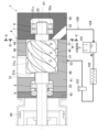
- FIG. 1 is a longitudinal sectional view showing a screw compressor according to a first embodiment of the present invention, and a system diagram showing an external route for oil supply to the screw compressor.
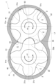
- FIG. 2 is a sectional view of the screw compressor according to the first embodiment of the present invention, taken along the line II-II shown in FIG. 1.
- FIG. This is an enlarged view of a portion indicated by the symbol L1 in FIG. 2, and is a diagram illustrating an axial communication path.
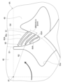
- FIG. 2 is a sectional view of the screw compressor according to the first embodiment of the present invention, taken along the line IV-IV shown in FIG. 1.
- FIG. 5 is an enlarged view of a portion indicated by the reference numeral L2 in FIG.
- FIG. 4 showing a groove structure of a casing in a screw compressor according to a first embodiment of the present invention.
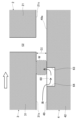
- FIG. FIG. 6 is a cross-sectional view of the groove structure of the casing in the screw compressor according to the first embodiment of the present invention, viewed from the direction of the VI-VI arrow shown in FIG. 5.
- FIG. It is a figure explaining the effect
- FIG. 9 is a diagram illustrating the relationship between the groove shape and the shear force and centrifugal force acting on the liquid in the groove, taking one groove of the groove structure of the casing shown in FIG. 8 as a representative. It is a figure explaining the effect
- FIG. 1 is a longitudinal sectional view showing a screw compressor according to a first embodiment of the present invention, and a system diagram showing an external route for oil supply to the screw compressor.
- FIG. 2 is a cross-sectional view of the screw compressor according to the first embodiment of the present invention, taken along the line II--II shown in FIG.
- the left side is the axial suction side of the screw compressor
- the right side is the axial discharge side.
- the thick arrow indicates the rotation direction of the screw rotor
- the two-dot chain line indicates the discharge port of the casing projected toward the discharge side end face of both the male and female rotors. Note that in FIG. 2, the outer peripheral surface side of the casing is omitted.
- an oil-fed screw compressor 1 (hereinafter referred to as a screw compressor), oil (liquid) is supplied from the outside into the compressor. Therefore, the screw compressor 1 is connected to an external oil supply system 100 that supplies oil.
- the external oil supply system 100 includes, for example, devices such as an oil separator 101, an oil cooler 102, and an oil filter 103, and a pipe line 104 that connects them.
- a screw compressor 1 has a male rotor 2 (male screw rotor) and a female rotor 3 (female screw rotor) that mesh with each other and rotate.
- the casing 4 is rotatably accommodated in the state.
- the male rotor 2 and the female rotor 3 are arranged so that their central axes A1 and A2 are parallel to each other.
- the male rotor 2 is rotatably supported on both sides in the axial direction (left and right direction in FIG. 1) by a suction side bearing 6 and discharge side bearings 7 and 8, respectively, and is connected to a motor 90 which is a rotational drive source. has been done.
- the female rotor 3 is rotatably supported on both sides in the axial direction by a suction side bearing and a discharge side bearing (both not shown).
- the male rotor 2 includes a rotor tooth portion 21 having a plurality of twisted male teeth (lobes) 21a (four in FIG. 2), and a suction side (in FIG. 1) provided at both ends of the rotor tooth portion 21 in the axial direction. , left side) and a shaft portion 23 on the discharge side (right side in FIG. 1).
- the rotor tooth portion 21 has a suction side end surface 21b and a discharge side end surface 21c at one end (left end in FIG. 1) and the other end (right end in FIG. 1) in the axial direction, respectively.
- the shaft portion 22 on the suction side extends to the outside of the casing 4, and is configured integrally with the shaft portion of the motor 90, for example.
- a shaft sealing member 9 such as an oil seal or a mechanical seal is attached to the suction side shaft portion 22 on the distal end side of the suction side bearing 6 .
- the female rotor 3 has a rotor tooth portion 31 having a plurality of twisted female teeth (lobes) 31a (six in FIG. 2), and a rotor tooth portion 31 having a plurality of twisted female teeth (lobes) 31a at both ends of the rotor tooth portion 31 in the axial direction (direction perpendicular to the paper plane of FIG. 2). It is comprised of a shaft part (not shown) on the suction side and a shaft part 33 on the discharge side.
- the rotor tooth portion 31 has a suction side end face (not shown) and a discharge side end face 31c at one end and the other end in the axial direction, respectively.
- the casing 4 includes a main casing 41 and a discharge side casing 42 attached to the axial discharge side of the main casing 41 (on the right side in FIG. 1).
- a housing chamber (bore) 45 is formed inside the casing 4 to accommodate the rotor teeth 21 of the male rotor 2 and the rotor teeth 31 of the female rotor 3 in a mutually meshed state.
- the storage chamber 45 is formed by closing an opening on one side (the right side in FIG. 1) of two partially overlapping cylindrical spaces formed in the main casing 41 with the discharge side casing 42.
- the wall surface forming the storage chamber 45 includes a substantially cylindrical male-side inner circumferential surface 46 that covers the radially outer side of the rotor teeth 21 of the male rotor 2 , and a substantially cylindrical male side inner peripheral surface 46 that covers the radially outer side of the rotor teeth 31 of the female rotor 3 .
- the discharge side inner wall surface 49 faces the discharge side end surfaces 21c and 31c of the portions 21 and 31.
- the rotor teeth 21 and 31 of both the male and female rotors 2 and 3 are arranged with a gap of several tens to hundreds of ⁇ m between them and the male inner circumferential surface 46 and the female inner circumferential surface 47 of the casing 4, respectively. There is.
- discharge side end surfaces 21c and 31c of both the male and female rotors 2 and 3 face the discharge side inner wall surface 49 of the casing 4 with a gap of several tens to hundreds of ⁇ m (hereinafter referred to as discharge side end surface gap G1). ing.
- the rotor teeth 21 and 31 of both the male and female rotors 2 and 3 and the inner wall surfaces of the housing chamber 45 of the casing 4 surrounding them male side inner circumferential surface 46, female side inner circumferential surface 47, suction side inner wall surface 48, discharge side A plurality of working chambers C having different pressures are formed by the inner wall surface 49).
- suction side bearings 6 for the male rotor 2 and female rotor 3 are provided at the end of the main casing 41 on the motor 90 side.
- a cover 43 is attached.
- the discharge side bearings 7 and 8 on the side of the male rotor 2 and the female rotor 3 are arranged in the discharge side casing 42 .
- the casing 4 is provided with a suction flow path 51 for sucking air into the working chamber C (accommodation chamber 45). Further, the casing 4 is provided with a discharge passage 52 for discharging compressed air from the working chamber C to the outside.
- the discharge flow path 52 communicates the storage chamber 45 (working chamber C) with the outside of the casing 4 and is connected to the external oil supply system 100.
- the discharge flow path 52 has a discharge port 52a (the portion indicated by the chain double-dashed line in FIG. 2) formed on the discharge side inner wall surface 49 of the casing 4.
- the casing 4 is provided with an oil supply path 53 for supplying oil from the external oil supply system 100 to the working chamber C (accommodation chamber 45).
- the oil supply path 53 opens, for example, to a region of the storage chamber 45 where the working chamber C is in the compression stroke.
- the motor 90 shown in FIG. 1 drives the male rotor 2, thereby rotationally driving the female rotor 3 shown in FIG.
- the working chamber C moves in the axial direction as the male and female rotors 2 and 3 rotate.
- the working chamber C sucks in air from the outside through the suction channel 51 shown in FIG. 1 by increasing its volume, and compresses the air to a predetermined pressure by reducing its volume.
- the working chamber C communicates with the discharge port 52a, the compressed air in the working chamber C passes through the discharge passage 52 through the discharge port 52a and is discharged to the oil separator 101 of the external oil supply system 100.
- oil is supplied to the working chamber C, so oil is mixed in the compressed air discharged. Oil contained in this compressed air is separated by an oil separator 101. The compressed air from which oil has been removed by the oil separator 101 is supplied to external equipment as needed.
- the oil separated from the compressed air by the oil separator 101 is cooled by the oil cooler 102 of the external oil supply system 100 and then injected into the working chamber C via the oil supply path 53 of the screw compressor 1.
- Oil can be supplied to the screw compressor 1 using the pressure of compressed air flowing into the oil separator 101 as a driving source, without using a power source such as a pump.
- FIG. 3 is an enlarged view of the portion indicated by the symbol L1 in FIG. 2, and is a view for explaining the axial communication path.
- the thick arrows represent the rotation directions of both the male and female rotors
- the two-dot chain lines represent the discharge ports projected onto the discharge side end surfaces of the male and female rotors.
- the tooth surface on the rotation direction side is the advancing surface 21d of the male rotor 2
- the tooth surface on the opposite side to the rotation direction is the tooth surface of the male rotor 2. It is defined as a backward movement surface 21e.
- the tooth surface on the rotation direction side is defined as the forward movement surface 31d of the female rotor 3
- the tooth surface on the opposite side to the rotation direction is defined as the backward movement surface 31e of the female rotor 3.
- the male rotor 2 and 3 show the meshing state of the male and female rotors 2 and 3 at a certain rotation angle.
- the male rotor 2 and the female rotor 3 theoretically have a first position where, as shown in FIG. A contact point P1, a second contact point P2 where the part on the tooth tip side of the backward movement surface 21e of the male rotor 2 and the part on the tooth bottom side of the backward movement surface 31e of the female rotor 3 come into contact with each other with respect to the first contact point P1, the male rotor There is a meshing state in which the advancing surface 21d of the female rotor 3 contacts the advancing surface 31d of the female rotor 3 at a total of three contact points P3.
- the area surrounded by the first contact point P1, the second contact point P2, and the tooth profile of both the male and female rotors 2 and 3 is an internal gap called an axial communication path G2.
- the axial communication path G2 is a crescent-shaped opening that is sandwiched between the backward moving surfaces 21e and 31e of both the male and female rotors 2 and 3 and opens only in the axial direction at the discharge side end surfaces 21c and 31c.
- the axial communication path G2 appears periodically on the discharge side end surfaces 21c and 31c in response to changes in meshing due to rotation of both the male and female rotors 2 and 3.
- the axial communication path G2 is located at the intersection of the outer diameter line D1 of the male rotor 2 (broken line in FIG. 3) and the pitch circle D2 of the female rotor 3 (broken line in FIG. 3) on the discharge port 52a side. occurs in the vicinity of the intersection P0 of ), and finally disappears when the meshing state of contact at three locations is resolved.
- the range of the first contact point P1 is inside the pitch circle D2 of the female rotor 3
- the range of the second contact point P2 is inside the outer diameter line D1 of the male rotor 2.
- the center of the pitch circle D2 of the female rotor 3 is the same as the central axis A2 of the female rotor 3, and its diameter dpf is calculated by the following equation (1).
- a, Zm, and Zf are the distance between the central axis A1 of the male rotor 2 and the central axis A2 of the female rotor 3, the number of teeth of the male rotor 2, and the number of teeth of the female rotor 3, respectively.
- the axial communication passage G2 is connected to the working chamber C of the suction stroke which is a relatively low pressure space, while the discharge flow passage 52 which is a relatively high pressure space (see FIG. 1) is connected to the working chamber C of the suction stroke which is a relatively low pressure space. ) and the discharge stroke working chamber Cd communicating with the discharge port 52a. Therefore, the axial communication passage G2 becomes a cause of compressed air flowing back from the discharge passage 52 and the working chamber Cd of the discharge stroke to the working chamber C of the suction stroke.
- the discharge side inner wall surface 49 of the casing 4 is designed to shield at least a portion, preferably most of the locus of the axial communication path G2. It has a shielding area 49a (see FIG. 4, which will be described later).
- a part of the compressed air in the working chamber Cd and the discharge passage 52 in the discharge stroke is transmitted to the discharge side end surfaces 21c and 31c of both the male and female rotors 2 and 3 and the shielding area 49a of the discharge side inner wall surface 49 of the casing 4. It reaches the axial communication path G2 through the discharge side end face gap G1 (see FIG. 1) between them, and flows back into the low pressure space. This is one of the factors that reduce the compression performance and energy saving performance of the compressor.
- the oil supplied into the working chamber C forms an oil film in a portion of the discharge side end gap G1, thereby reducing internal leakage of compressed air through the discharge side end gap G1.
- Expected to be effective the pressure difference between the high pressure space from which the leak originates (working chamber Cd in the discharge stroke and the discharge flow path 52) and the low pressure space to which the leak occurs (working chamber C in the suction stroke) is larger than other cases of internal leakage, it is difficult to maintain the oil film formed in the discharge side end face gap G1 near the axial communication path G2, and the effect of reducing internal leakage due to the oil film tends to be small.
- the present embodiment is characterized by having a groove structure for increasing the pressure of the oil film formed in the discharge side end face gap G1 near the axial communication path G2.
- the groove structure is particularly intended to form a high-pressure oil film along the longitudinal direction of the flat crescent-shaped axial communication path G2.
- FIG. 4 is a cross-sectional view of the screw compressor according to the first embodiment of the present invention, taken along the line IV-IV shown in FIG.
- FIG. 5 shows the groove structure of the casing in the screw compressor according to the first embodiment of the present invention, and is an enlarged view of the portion indicated by the symbol L2 in FIG. 4.
- the two-dot chain line represents the shape of the discharge side end surfaces of the male and female rotors projected in the axial direction onto the discharge side inner wall surface of the casing at a certain rotation angle (when the axial communication path is formed).
- thick arrows indicate the rotation direction of both rotors.
- thick arrows indicate the rotation direction of the female rotor. Note that in FIG. 4, the outer peripheral surface side of the casing is omitted.
- a discharge port 52a is formed on the discharge side inner wall surface 49 of the casing 4, which is the entrance of the discharge flow path 52 (see FIG. 1).
- the discharge port 52a is formed, for example, in an area where the locus of the axial communication passage G2 is projected onto the discharge side inner wall surface 49 in the rotor axial direction. They are formed so that they generally do not overlap.
- the discharge side inner wall surface 49 has a shielding region 49a for suppressing internal leakage via the axial communication path G2.
- the shielding region 49a shields at least a part, preferably a large part, of the locus of the axial communication path G2, and includes at least a part of an area where the locus is projected onto the discharge side inner wall surface 49 in the rotor axial direction, Preferably, it is set to overlap with most of the areas.
- the shielding region 49a is a portion of a region surrounded by both the outer diameter line D1 of the male rotor 2 and the pitch circle D2 of the female rotor 3 projected onto the discharge side inner wall surface 49 in the rotor axial direction.
- the region is closer to the discharge port 52a than the line segment connecting the central axis A1 of the male rotor 2 and the central axis A2 of the female rotor 3.
- the outer edge of the shielding region 49a constitutes a part of the outline of the discharge port 52a, and has a shape, for example, like a tongue-like projection protruding toward the center of the discharge port 52a.
- the shielding region 49a of the discharge-side inner wall surface 49 makes the direct communication region (opposing region) between the axial communication path G2 and the discharge port 52a as small as possible.
- the shielding region 49a of the discharge side inner wall surface 49 includes a plurality of grooves 60 into which a part of the oil (liquid) supplied into the working chamber C can flow.
- a group is established.
- the plurality of grooves 60 are arranged in parallel in the circumferential direction with respect to the central axis A2 of the female rotor 3.
- Each groove 60 is formed as an elongated groove having a longitudinal direction, and the plurality of grooves 60 are arranged so that the sides extending in the longitudinal direction are adjacent to each other.
- the groove located on the front side in the rotational direction of the female rotor 3 has a relatively longer length in the longitudinal direction than the groove located on the rear side in the rotational direction of the female rotor 3. It is configured to be.
- the plurality of grooves 60 in the groove group are configured such that their longitudinal lengths become relatively longer as they advance in the rotational direction of the female rotor 3. This is intended to set the length of each groove 60 in the groove group in the longitudinal direction so as to correspond to the axial communication path G2, which becomes longer in the longitudinal direction as the rotation of the female rotor 3 progresses.
- each groove 60 has one end 61 in the longitudinal direction located closer to the outer circumference of the female rotor 3 than the other end 62, and for example, in the radial direction R2 of the female rotor 3. It extends linearly from the other side end 62 toward the one side end 61 along the line. That is, the groove 60 has normal lines Ng1, Ng2, and Ng3 (a first side surface 63 and a second side surface extending in the longitudinal direction) at each position from the other end 62 in the longitudinal direction to the one end 61 through the position 66.
- the normal line of the side surface 64 coincides with the tangent line of the circumferential direction of the female rotor 3 at the positions 62, 61, and 66 (direction perpendicular to the radial direction R2). Normal lines Ng1, Ng2, and Ng3 at each position 62, 61, and 66 in the longitudinal direction of each groove 60 point in the same direction.
- the first side surface 63 is a side surface located on the front side of the female rotor 3 in the rotational direction.
- the second side surface 64 is a side surface located on the rear side of the female rotor 3 in the rotational direction.
- the groove 60 is limited to a position inside the pitch circle D2 of the female rotor 3 and a position that does not reach the contour line of the shielding region 49a (the opening edge of the discharge port 52a). That is, the groove 60 extends from the vicinity of the contour line (opening edge of the discharge port 52a) on the female rotor 3 side in the shielding region 49a along the longitudinal direction of the flat crescent-shaped axial communication path G2 (see FIG. 4). It is configured to extend to the vicinity of the contour line on the male rotor 2 side (the opening edge of the discharge port 52a).
- the groove 60 has a substantially constant depth.
- the groove 60 is intended as a type of dynamic pressure groove, although the details will be described later.
- the depth of the groove 60 as a dynamic pressure groove has an appropriate value depending on the magnitude of the shear force, which will be described later, that acts on the oil flowing into the groove. For example, when the discharge side end face gap G1 is about several tens to 200 ⁇ m, the preferable depth of the groove 60 is in the range of 1 ⁇ m to 1 mm.
- FIG. 6 is a cross-sectional view of the groove structure of the casing in the screw compressor according to the first embodiment of the present invention, viewed from the direction of the arrow VI-VI shown in FIG.
- FIG. 7 is a diagram illustrating the effect of the groove structure of the casing in the screw compressor according to the first embodiment of the present invention.
- FIG. 6 shows the female rotor facing the shielded area of the casing.
- the white arrow indicates the direction of rotation of the female rotor
- the thick arrow indicates the flow of oil.
- the two-dot chain line shows the shapes of the discharge side end faces of both the male and female rotors projected onto the discharge side inner wall surface of the casing in the rotor axial direction.
- the oil flowing into each groove 60 formed in the shielding area 49a of the discharge side inner wall surface 49 of the casing 4 has a rotating female rotor as shown in FIG.
- the shearing force Sf is applied by the discharge side end surface 31c of No. 3 in the tangential direction (direction perpendicular to the radial direction R2 of the female rotor 3) of the rotational direction (circumferential direction) of the female rotor 3, and in the same direction as the rotational direction.
- each groove 60 extends linearly from the other side end 62 toward the one side end 61 along the radial direction R2 of the female rotor 3. That is, the directions of the normal lines Ng1, Ng2, and Ng3 at each position 62, 61, and 66 in the longitudinal direction of the groove 60 coincide with the tangential direction of the circumferential direction of the female rotor 3 at that position (direction perpendicular to the radial direction R2). Therefore, it coincides with the direction in which the shear force Sf acts. As a result, the oil in each groove 60 flows in the width direction of the groove 60 in the same direction as the rotation direction of the female rotor 3 due to the shear force Sf caused by the rotation of the female rotor 3 .
- the oil flowing in the groove 60 is dammed up by the first side surface 63, which is the side surface located on the front side in the direction of rotation of the female rotor 3 in the width direction of the groove 60.
- the kinetic energy (dynamic pressure) is converted, static pressure increases, and finally flows out to the discharge side end face gap G1 (female rotor 3 side) over the entire lengthwise region of the first side surface 63 of the groove 60.
- the oil pressure in the discharge side end face gap G1 becomes relatively high near the entire region in the longitudinal direction of the first side surface 63 of the groove 60. That is, the formation of the high-pressure oil film W along the longitudinal direction of the first side surface 63 of the groove 60 is promoted in the discharge side end face gap G1.
- a plurality of grooves 60 are arranged side by side so that the sides extending in the longitudinal direction are adjacent to each other. Therefore, the oil pressurized from each first side surface 63 of the plurality of grooves 60 (the side surface located on the front side in the rotational direction of the female rotor 3 among both side surfaces extending in the longitudinal direction of the groove) is transferred to the discharge side end surface gap. It leaks into G1. Thereby, a plurality of high-pressure oil films W are formed so as to be lined up in the circumferential direction (rotation direction) of the female rotor 3.
- the oil in the groove 60 not only seals the discharge side end face gap G1, but also closes the contour of the female rotor 3 side (outer diameter line D1 side) in the shielding area 49a of the casing 4 to the male rotor 2 side.
- An oil film W having a higher pressure than the surroundings is formed by the oil flowing out from the first side surface 63 of the groove 60 up to the vicinity of the contour (on the pitch circle D2 side).
- This high-pressure oil film W is formed in the discharge flow path 52 (see FIG. 1), the working chamber Cd of the discharge stroke (see FIG. 3), etc. in a state where the axial communication path G2 overlaps with the shielding region 49a via the discharge side end face gap G1.
- the groove structure (a plurality of grooves 60) of this embodiment forms a high-pressure oil film W by converting dynamic pressure into static pressure by damming oil flowing due to shear force Sf at the first side surface 63 in the groove width direction. It can be said to be a type of dynamic pressure groove.
- the depth of each groove 60 can be set to an appropriate value (for example, in the range of 1 ⁇ m to 1 mm) that can maximize the pressure of the oil film W, depending on the magnitude of the shear force Sf acting on the oil and the magnitude of the discharge side end face gap G1. ), internal leakage via the axial communication path G2 can be further suppressed.
- each groove 60 is arranged inside the pitch circle D2 of the female rotor 3, and is formed so as not to communicate with the discharge port 52a. This prevents the plurality of grooves 60 from simultaneously communicating with the working chamber Cd of the discharge stroke and the axial communication path G2 and becoming a path for internal leakage.
- a plurality of grooves 60 are provided in the casing 4, which is a part of the stationary body. Therefore, since the plurality of grooves 60 do not move together with the screw rotor and are at fixed positions with respect to the locus of the discharge port 52a of the casing 4 and the axial communication passage G2, internal leakage through the axial communication passage G2 is prevented. A stable suppressive effect can be expected.
- the screw compressor 1 includes a male rotor 2 having a first discharge end face 21c on one axial side, and a female rotor 2 having a second discharge end face 31c on one axial side. 3, and a casing 4 having a housing chamber 45 that rotatably accommodates the male rotor 2 and the female rotor 3 in an engaged state.
- the casing 4 has a discharge side inner wall surface 49 that faces the first discharge side end surface 21 c of the male rotor 2 and the second discharge side end surface 31 c of the female rotor 3 .
- normal lines Ng1, Ng2, and Ng3 at each position 62, 61, and 66 in the longitudinal direction coincide with a tangent to the circumferential direction of the female rotor 3 at the corresponding position (a direction perpendicular to the radial direction R2 of the female rotor 3). It is configured as follows.
- the oil (liquid) in the groove 60 provided on the discharge side inner wall surface 49 of the casing 4 is spread in the groove width direction over the entire length of the groove by the shear force Sf caused by the rotation of the female rotor 3.
- a high-pressure oil film W liquid film is formed in the longitudinal direction of the flat crescent-shaped axial communication path G2 in the discharge side end face gap G1. can be formed. Therefore, internal leakage of compressed gas via the axial communication path G2 can be reduced.
- the groove 60 is configured to extend linearly along the radial direction of the female rotor 3. According to this configuration, it is easy to process the groove 60 on the casing 4.
- a groove group having a plurality of grooves 60 is provided in the shielding region 49a of the casing 4, and the grooves 60 of the groove group are such that the sides extending in the longitudinal direction of the grooves 60 are adjacent to each other. They are arranged in parallel in the circumferential direction of the female rotor 3. According to this configuration, a plurality of high-pressure oil films W (fluid films) can be formed in the moving direction of the axial communication path G2. Therefore, internal leakage of compressed gas via the axial communication path G2 can be further reduced.
- the grooves located on the front side in the rotational direction of the female rotor 3 have a longer length in the longitudinal direction than the grooves located on the rear side in the rotational direction of the female rotor 3. is constructed so that it is long. According to this configuration, the length in the longitudinal direction of each groove 60 of the groove group can be made to correspond to the length of the axial communication path G2, which becomes longer in the longitudinal direction as the rotation of the female rotor 3 progresses.
- FIG. 8 shows a groove structure of a casing in a screw compressor according to a second embodiment of the present invention, and is an enlarged view similar to FIG. 5.
- FIG. 9 is a diagram illustrating the relationship between the groove shape and the shear force and centrifugal force acting on the liquid in the groove, using one of the groove structures of the casing shown in FIG. 8 as a representative.
- thick arrows indicate the rotation direction of the female rotor.
- the two-dot chain line shows the shapes of the discharge side end surfaces of both the male and female rotors projected onto the discharge side inner wall surface of the casing in the rotor axial direction.
- the screw compressor according to the second embodiment shown in FIGS. 8 and 9 differs from the first embodiment in that a high-pressure oil film W is formed in the longitudinal direction of the axial communication passage G2 on the discharge side inner wall surface of the casing 4A.
- the difference is that the shapes (groove structures) of the plurality of grooves 60A provided in the grooves 49 are different.
- the groove structure of this embodiment is determined by considering the centrifugal force Cf in addition to the shear force Sf caused by the rotation of the female rotor 3 as a force acting on the oil (liquid) in the groove 60A. .
- the shielding region 49a of the discharge side inner wall surface 49 is configured with a plurality of grooves 60A into which a part of the oil (liquid) supplied into the working chamber C can flow.
- a group of grooves is formed.
- the plurality of grooves 60A are juxtaposed in the circumferential direction with respect to the central axis A2 of the female rotor 3.
- Each groove 60A is formed as an elongated groove having a longitudinal direction extending from the inner circumferential side to the outer circumferential side of the female rotor 3.
- One end 61 of the groove 60A in the longitudinal direction is located closer to the outer circumference of the female rotor 3 than the other end 62.
- the plurality of grooves 60A are arranged so that the sides extending in the longitudinal direction are adjacent to each other.
- the plurality of grooves 60A are configured such that the groove located on the front side in the rotational direction of the female rotor 3 has a longer length in the longitudinal direction than the groove located on the rear side in the rotational direction of the female rotor 3. There is.
- Each groove 60A has a longitudinal direction extending from the other side end 62 toward the one side end 61 (from the inner circumferential side to the outer circumferential side of the female rotor 3) with respect to the radial direction R2 of the female rotor 3. It is configured to be inclined in a direction opposite to the rotation direction.
- the groove 60A is formed in a convex curved shape in the rotational direction of the female rotor 3. In this structure, as shown in FIG. 9, in addition to the shear force Sf caused by the rotation of the female rotor 3, centrifugal force caused by the rotation of the female rotor 3 acts on the oil (liquid) in the groove 60A. This is set in consideration of Cf.
- the rotation of the female rotor 3 causes the fluid to flow in the circumferential direction of the female rotor 3 because it is dragged by the discharge side end surface 31c of the female rotor 3.
- the magnitude of the centrifugal force Cf acting on the liquid may not be negligible compared to the shear force Sf caused by the rotation of the female rotor 3.
- the plurality of grooves 60A in this embodiment are also intended to form a high-pressure oil film along the longitudinal direction of the flat crescent-shaped axial communication path G2. Therefore, the normal lines Ng1, Ng2, Ng3 at each position in the longitudinal direction of each groove 60A are the shear forces Sf1, Sf2, Sf3 caused by the rotation of the female rotor 3 and the centrifugal forces Cf1, Cf2 caused by the rotation of the female rotor 3. , Cf3, and the direction of the resultant force F1, F2, F3.
- the direction of the resultant force F1, F2, F3 at each position in the longitudinal direction of the groove 60A is the centrifugal force Cf1, Cf2 with respect to the direction of the shear force Sf1, Sf2, Sf3 (direction perpendicular to the radial direction R2 of the female rotor 3). , Cf3. Therefore, when trying to align the normal lines Ng1, Ng2, Ng3 at each position in the longitudinal direction of the groove 60A with the direction of the resultant force F1, F2, F3, as shown in FIG.
- the longitudinal direction from the other side end 62 to the one side end 61 with respect to direction R2 is inclined in a direction opposite to the rotational direction of the female rotor 3, and the groove 60A has a curved shape convex in the rotational direction of the female rotor 3. become.
- the direction of the normal line N at each position in the longitudinal direction of the groove 60A, that is, the direction of the normal line of the first side surface 63A and the second side surface 64A of the groove 60A, for example, as follows.
- the direction of the normal line of the first side surface 63A and the second side surface 64A of the groove 60A for example, as follows.
- the distances from the central axis A2 of the female rotor 3 to the other end 62, one end 61, and position 66 of the groove 60A are r1, r2, and r3, respectively.
- the resultant forces F1, F2, and F3 at the other end 62, one end 61, and position 66 of the groove 60A are based on the following equations (2) to (4), and the shear forces Sf1, Sf2, and Sf3 are Based on the following equations (5) to (7), centrifugal forces Cf1, Cf2, and Cf3 can be calculated based on the following equations (8) to (10).
- ⁇ is the viscosity coefficient of oil (liquid)
- ⁇ A is the area of each position 62, 61, and 66
- h is the size of the discharge side end face gap G1 and the depth of the groove 60A.
- the sum of the values, ⁇ indicates the angular velocity of the female rotor 3.
- ⁇ m represents the mass of oil (liquid) at each position 62, 61, and 66
- ⁇ represents the angular velocity of the female rotor 3.
- the directions of the resultant forces F1, F2, and F3 at each position in the longitudinal direction of the groove 60A are as follows: Consider the angle ⁇ (inclination) in the directions of F1, F2, and F3. Specifically, the angles ⁇ 1, ⁇ 2, and ⁇ 3 of the resultant forces F1, F2, and F3 at the other end 62, one end 61, and position 66 of the groove 60A are calculated based on the following equations (11) to (13). It is possible to calculate.
- the normal lines Ng1, Ng2, Ng3 at each position 62, 61, 66 in the longitudinal direction are the shear forces Sf1, Sf2, Sf3 at the positions 62, 61, 66 and the centrifugal forces Cf1, Cf2. , Cf3, and the direction of the resultant force F1, F2, F3. That is, in each groove 60A, normal lines Ng1, Ng2, Ng3 at each position 62, 61, 66 in the longitudinal direction are tangents in the circumferential direction of the female rotor 3 at the positions 62, 61, 66 (radial direction R2 of the female rotor 3). is configured to have a constant inclination with respect to the direction perpendicular to
- FIG. 10 is a diagram illustrating the effect of the groove structure of the casing in the screw compressor according to the second embodiment of the present invention.
- each groove 60A in this embodiment has normal lines Ng1, Ng2, and Ng3 (a first side surface 63 and a second side surface extending in the longitudinal direction) at each position 62, 61, and 66 in the longitudinal direction. 64) coincides with the direction of the resultant force F1, F2, F3 of the shear force Sf1, Sf2, Sf3 and the centrifugal force Cf1, Cf2, Cf3 at each of the positions 62, 61, 66.
- Ng1, Ng2, and Ng3 a first side surface 63 and a second side surface extending in the longitudinal direction
- the oil in each groove 60A is moved in the width direction of the groove 60A in the same direction as the rotation direction of the female rotor 3 due to the shear force Sf and centrifugal force Cf caused by the rotation of the female rotor 3. flow in a direction.
- the oil flowing in the groove 60A is blocked by the first side surface 63A in the width direction of the groove 60A, converting kinetic energy (dynamic pressure) and increasing the static pressure. It flows out into the discharge side end face gap G1 (female rotor 3 side) over the entire longitudinal region of the side surface 63A.
- the oil pressure in the discharge side end face gap G1 becomes relatively high near the entire region in the longitudinal direction of the first side surface 63A of the groove 60A. That is, in the discharge side end face gap G1, the formation of the high pressure oil film W along the longitudinal direction of the first side surface 63A of the groove 60A is promoted.
- a plurality of grooves 60A are arranged side by side so that the sides extending in the longitudinal direction are adjacent to each other. Therefore, the pressurized oil flows out from each first side surface 63A of the plurality of grooves 60A to the discharge side end face gap G1. Thereby, a plurality of high-pressure oil films W are formed so as to be lined up in the circumferential direction (rotation direction) of the female rotor 3.
- the oil in the groove 60A not only seals the discharge side end face gap G1, but also closes the contour of the female rotor 3 side (outer diameter line D1 side) in the shielding area 49a of the casing 4A to the male rotor 2 side.
- An oil film W having a higher pressure than the surroundings is formed by the oil flowing out from the first side surface 63A of the groove 60A up to the vicinity of the contour (on the pitch circle D2 side).
- This high-pressure oil film W is formed in the discharge flow path 52 (see FIG. 1) and the working chamber Cd of the discharge stroke (see FIG. 3) in a state where the axial communication path G2 overlaps with the shielding region 49a via the discharge side end face gap G1.
- the groove structure (a plurality of grooves 60A) of the present embodiment dams up oil flowing due to shear force Sf and centrifugal force Cf at the first side surface 63A in the groove width direction, thereby converting dynamic pressure into static pressure and creating a high pressure. It forms an oil film W, and can be said to be a type of dynamic pressure groove.
- the depth of each groove 60A is set to an appropriate value (for example, 1 ⁇ m 1 mm), internal leakage via the axial communication path G2 can be further suppressed.
- the screw compressor 1 includes a male rotor 2 having a first discharge end face 21c on one axial side, and a female rotor 2 having a second discharge end face 31c on one axial side.
- the rotor 3 is provided with a casing 4 having a housing chamber 45 that rotatably accommodates the male rotor 2 and the female rotor 3 in an engaged state.
- the casing 4 has a discharge side inner wall surface 49 that faces the first discharge side end surface 21 c of the male rotor 2 and the second discharge side end surface 31 c of the female rotor 3 .
- the groove 60A is configured such that the longitudinal direction from the inner circumferential side to the outer circumferential side of the female rotor 3 is inclined with respect to the radial direction R2 of the female rotor 3 in a direction opposite to the rotational direction of the female rotor 3. It is formed in a convex curved shape in the rotational direction of the rotor 3. Furthermore, the groove 60A has normal lines Ng1, Ng2, Ng3 at each position 62, 61, 66 in the longitudinal direction as a tangent in the circumferential direction of the female rotor 3 at the positions 62, 61, 66 (radial direction R2 of the female rotor 3). It is configured to have a constant inclination with respect to the direction perpendicular to the direction.
- the oil (liquid) in the groove 60A provided in the discharge side inner wall surface 49 of the casing 4A is spread over the entire longitudinal direction of the groove by the shear force Sf and centrifugal force Cf caused by the rotation of the female rotor 3.
- the static pressure increases as it flows in the groove width direction and is blocked by the first side surface 63A of the groove 60A. Therefore, a high-pressure oil film W (fluid film) can be formed in the longitudinal direction of the flat crescent-shaped axial communication path G2 in the discharge side end face gap G1. Therefore, internal leakage of compressed gas via the axial communication path G2 can be reduced.
- a groove group having a plurality of grooves 60A is provided in the shielding region 49a of the casing 4A, and the grooves 60A of the groove group are such that the sides extending in the longitudinal direction of the grooves 60A are adjacent to each other. They are arranged in parallel in the circumferential direction of the female rotor 3.
- a plurality of high-pressure oil films W liquid films
- a plurality of high-pressure oil films W can be formed in the moving direction of the axial communication path G2. Therefore, internal leakage of compressed gas via the axial communication path G2 can be further reduced. Therefore, internal leakage of compressed gas via the axial communication path G2 can be further reduced.
- the grooves located on the front side in the rotational direction of the female rotor 3 have a longer length in the longitudinal direction than the grooves located on the rear side in the rotational direction of the female rotor 3. is constructed so that it is long. According to this configuration, the length in the longitudinal direction of each groove 60A of the groove group can be made to correspond to the length of the axial communication path G2, which becomes longer in the longitudinal direction as the rotation of the female rotor 3 progresses.
- the screw compressor 1 that compresses air has been described as an example, but the present invention can also be applied to a screw compressor that compresses various gases such as ammonia and CO2 refrigerants. Can be done. Further, although the explanation has been given by taking the oil-supplied screw compressor 1 as an example, the present invention can also be applied to a screw compressor to which liquid other than oil is supplied. Although oil is preferred from the viewpoint of sealing performance and ease of forming a liquid film, it can be replaced with various liquids having sufficient properties to form a liquid film, such as water.
- each embodiment can be similarly applied to a liquid-free screw compressor in which a liquid such as oil is not supplied into the working chamber.
- a liquid such as oil
- compressed air exists instead of oil in the grooves on the discharge side end surface of the rotor or the discharge side inner wall surface of the casing.
- FIGS. 6 and 7. When the oil is replaced with air, a shearing force Sf acts on the air existing in the groove 60 due to friction with the discharge side end surface 31c of the female rotor 3 which has a relative speed and faces the female rotor 3.
- the air within the groove 60 flows in the width direction throughout the length of the groove 60 due to the shear force Sf.
- the air flowing in the groove width direction is blocked at the first side surface 63 of the groove 60, and as a result flows out into the discharge side end face gap G1. Therefore, in the discharge side end face gap G1, an area W where the air pressure is relatively high compared to the surrounding area is generated near the entire area in the longitudinal direction of the first side surface 63 of the groove 60.
- the internal leakage amount of air through the end gap increases as the pressure difference between the high-pressure working chamber on the upstream side and the end gap on the downstream side increases.
- the groove 60 is provided as described above, the pressure in the vicinity of the entire longitudinal region of the first side surface 63 of the groove 60 increases in the discharge side end face gap G1, so that the pressure between the working chamber Cd of the discharge stroke and the discharge side end face gap G1 increases. G1 is reduced compared to the case without the groove 60. Therefore, by providing the groove 60, it is possible to suppress internal leakage of air.
- the present invention is not limited to the embodiments described above, and includes various modifications.
- the embodiments described above have been described in detail to explain the present invention in an easy-to-understand manner, and are not necessarily limited to those having all the configurations described. That is, it is also possible to add, delete, or replace some of the configurations of each embodiment with other configurations.
- the grooved casing or the male and female rotors it is possible to use, for example, a processing method such as molding or cutting.
- a processing method such as molding or cutting.
- the data used in the three-dimensional modeling machine is generated by processing 3D data generated by CAD, CG software, or a 3D scanner into NC data using a CAM. Modeling is performed by inputting the data into a three-dimensional model using an arbitrary method.
- NC data may be generated directly from 3D data using CAD/CAM software.
Landscapes
- Engineering & Computer Science (AREA)
- Mechanical Engineering (AREA)
- General Engineering & Computer Science (AREA)
- Applications Or Details Of Rotary Compressors (AREA)
- Compressor (AREA)
Abstract
スクリュー圧縮機のケーシングは、雄ロータ及び雌ロータの吐出側端面に対向する吐出側内壁面を有する。ケーシングの吐出側内壁面は、雄ロータ及び雌ロータの回転よる噛合いの変化に応じて吐出側端面において周期的に現れ雄ロータ及び雌ロータの後進面同士によって挟まれた隙間であるアキシャル連通路の軌跡の少なくとも一部を遮蔽する遮蔽領域を有する。ケーシング4の遮蔽領域内に、長手方向を有する溝が設けられている。溝は、長手方向の各位置における法線が当該位置における雌ロータの周方向の接線(雌ロータの径方向に対して直交する方向)に一致するように構成されている。
Description
本発明は、スクリュー圧縮機に係り、更に詳しくは、互いに噛み合う一対のスクリューロータを備えるスクリュー圧縮機に関する。
スクリュー圧縮機の性能を低下させる要因の代表的なものとして、圧縮気体の内部漏洩がある。圧縮気体の内部漏洩とは、圧縮が進んで圧力が上昇した高圧の空間から、圧縮の開始前や圧縮が進んでいない相対的に低圧の空間へ、圧縮された気体が逆流してしまう現象をいう。この内部漏洩は、エネルギを要して圧縮した気体が低圧状態に戻ってしまうので、エネルギ損失となる。
圧縮気体の内部漏洩を抑制する手段の一例として、特許文献1に記載の技術が知られている。特許文献1に開示された油冷式スクリュー圧縮機では、一対のスクリューロータのロータ軸間におけるロータ室の吐出側端壁に、ロータ軸間方向を長さ方向とした複数のラビリンス溝を設けている。
特許文献1に記載の技術は、スクリューロータの吐出側端面とロータ室の吐出側端壁間に形成された間隙(以下、吐出側端面隙間と称することがある)のうち、最も高圧の吐出行程の圧縮作用空間31Hと当該高圧の圧縮作用空間に隣接する吸気閉込み前又は吸気閉込み直後の低圧の圧縮作用空間31Lとの間に位置する部分をシールするものである。しかし、圧縮気体の内部漏洩の経路となる内部隙間は、吐出側端面隙間の上述部分の他にも、複数存在する。特許文献1に記載の技術では、吐出側端面隙間の上述部分以外の内部隙間を介した圧縮気体の内部漏洩の抑制については考慮されておらず、内部漏洩の低減について改良の余地がある。
内部隙間の一例として、アキシャル連通路と称する隙間がある。アキシャル連通路は、雄雌両ロータの回転による噛合いの変化に応じて吐出側端面に周期的に現れる隙間であって、両ロータの後進面同士に挟まれて軸方向のみに開口する偏平な三日月形状の開口部である。アキシャル連通路を介して、相対的に低圧の空間である吸込行程の作動室と相対的に高圧の空間となる吐出流路(吐出空間)とが連通するので、当該アキシャル連通路は圧縮気体が逆流する要因となる。アキシャル連通路を介した内部漏洩の経路は、吐出側端面に存在する複数の内部漏洩の経路のなかでも、漏洩元の高圧空間と漏洩先の低圧空間の圧力差が特に大きいので、その漏洩量が多くなる傾向にある。アキシャル連通路を介した内部漏洩は、特許文献1に記載のように作動室内に油などの液体が供給される給液式のスクリュー圧縮機であっても、作動室内に液体が供給されずに駆動する無給液式のスクリュー圧縮機であっても、共通の課題である。
本発明は上記の問題点を解消するためになされたものであり、その目的の一つはアキシャル連通路を介した圧縮気体の内部漏洩を低減することができるスクリュー圧縮機を提供するものである。
本願は上記課題を解決する手段を複数含んでいるが、その一例を挙げるならば、軸方向一方側に第1の吐出側端面を有する雄ロータと、軸方向一方側に第2の吐出側端面を有する雌ロータと、前記雄ロータ及び前記雌ロータを噛み合った状態で回転可能に収容する収容室を有するケーシングとを備え、前記ケーシングは、前記雄ロータの前記第1の吐出側端面及び前記雌ロータの前記第2の吐出側端面に対向する吐出側内壁面を有し、前記ケーシングの前記吐出側内壁面は、前記雄ロータ及び前記雌ロータの回転よる噛合いの変化に応じて前記第1の吐出側端面及び前記第2の吐出側端面において周期的に現れ前記雄ロータ及び前記雌ロータの後進面同士によって挟まれた隙間であるアキシャル連通路の軌跡の少なくとも一部を遮蔽する遮蔽領域を有し、前記ケーシングの前記遮蔽領域内に長手方向を有する溝が設けられ、前記溝は、前記長手方向の各位置における法線が当該位置における前記雌ロータの周方向の接線と一致するように構成されていることを特徴とする。
本発明の一例によれば、ケーシングの吐出側内壁面に設けた溝内の液体又は気体(流体)が雌ロータの回転に起因するせん断力によって溝長手方向の全体に亘って溝幅方向に流動し溝の側面に堰き止められることで静圧が上昇するので、吐出側端面隙間における偏平な三日月形状のアキシャル連通路の長手方向に高圧の流体膜を形成することができる。したがって、アキシャル連通路を介した圧縮気体の内部漏洩を低減することができる。
上記した以外の課題、構成及び効果は、以下の実施形態の説明により明らかにされる。
上記した以外の課題、構成及び効果は、以下の実施形態の説明により明らかにされる。
以下、本発明によるスクリュー圧縮機の実施形態について図面を用いて例示説明する。本実施の形態は、空気を圧縮する給油式のスクリュー圧縮機に本発明を適用した例である。
[第1の実施形態]
第1の実施形態に係るスクリュー圧縮機の基本構成を図1及び図2を用いて説明する。図1は本発明の第1の実施形態に係るスクリュー圧縮機を示す縦断面図及び当該スクリュー圧縮機に対する給油の外部経路を示す系統図である。図2は本発明の第1の実施形態に係るスクリュー圧縮機を図1に示すII-II矢視から見た断面図である。図1中、左側がスクリュー圧縮機の軸方向吸込側、右側が軸方向吐出側である。図2中、太線の矢印はスクリューロータの回転方向を、二点鎖線は雄雌両ロータの吐出側端面側へ投影されたケーシングの吐出ポートを表している。なお、図2はケーシングの外周面側が省略されている。
第1の実施形態に係るスクリュー圧縮機の基本構成を図1及び図2を用いて説明する。図1は本発明の第1の実施形態に係るスクリュー圧縮機を示す縦断面図及び当該スクリュー圧縮機に対する給油の外部経路を示す系統図である。図2は本発明の第1の実施形態に係るスクリュー圧縮機を図1に示すII-II矢視から見た断面図である。図1中、左側がスクリュー圧縮機の軸方向吸込側、右側が軸方向吐出側である。図2中、太線の矢印はスクリューロータの回転方向を、二点鎖線は雄雌両ロータの吐出側端面側へ投影されたケーシングの吐出ポートを表している。なお、図2はケーシングの外周面側が省略されている。
図1において、給油式スクリュー圧縮機1(以下、スクリュー圧縮機という)では、外部から圧縮機内部に油(液体)が供給される。そこで、スクリュー圧縮機1には、油を供給する外部給油系統100が接続されている。外部給油系統100は、例えば、オイルセパレータ101、オイルクーラ102、オイルフィルタ103などの機器及びそれらを接続する管路104で構成されている。
図1及び図2において、スクリュー圧縮機1は、互いに噛み合い回転する雄ロータ2(雄型のスクリューロータ)及び雌ロータ3(雌型のスクリューロータ)と、雄雌両ロータ2、3を噛み合った状態で回転可能に内部に収容するケーシング4とを備えている。雄ロータ2及び雌ロータ3は、互いの中心軸線A1、A2が平行となるように配置されている。雄ロータ2は、その軸方向(図1中、左右方向)の両側がそれぞれ吸込側軸受6と吐出側軸受7、8とにより回転自在に支持されており、回転駆動源であるモータ90に接続されている。雌ロータ3は、その軸方向の両側がそれぞれ吸込側軸受と吐出側軸受(共に図示せず)とにより回転自在に支持されている。
雄ロータ2は、ねじれた雄歯(ローブ)21aを複数(図2では4つ)有するロータ歯部21と、ロータ歯部21の軸方向の両側端部にそれぞれ設けた吸込側(図1中、左側)のシャフト部22及び吐出側(図1中、右側)のシャフト部23とで構成されている。ロータ歯部21は、軸方向一方端(図1中、左端)及び他方端(図1中、右端)にそれぞれ吸込側端面21b及び吐出側端面21cを有している。吸込側のシャフト部22は、ケーシング4の外側に延出しており、例えば、モータ90のシャフト部と一体の構成である。吸込側のシャフト部22における吸込側軸受6よりも先端側には、オイルシール又はメカニカルシールなどの軸封部材9が取り付けられている。
雌ロータ3は、ねじれた雌歯(ローブ)31aを複数(図2では6つ)有するロータ歯部31と、ロータ歯部31の軸方向(図2の紙面直交方向)の両側端部にそれぞれ設けた吸込側のシャフト部(図示せず)及び吐出側のシャフト部33とで構成されている。ロータ歯部31は、軸方向一方端及び他方端にそれぞれ吸込側端面(図示せず)及び吐出側端面31cを有している。
ケーシング4は、主ケーシング41と、主ケーシング41の軸方向吐出側(図1中、右側)に取り付けられる吐出側ケーシング42とを備えている。
ケーシング4の内部には、雄ロータ2のロータ歯部21および雌ロータ3のロータ歯部31を互いに噛み合った状態で収容する収容室(ボア)45が形成されている。収容室45は、主ケーシング41に形成された一部重複する2つの円筒状空間の一方側(図1中、右側)の開口を吐出側ケーシング42で閉塞することによって形成される。収容室45を形成する壁面は、雄ロータ2のロータ歯部21の径方向外側を覆う略円筒状の雄側内周面46と、雌ロータ3のロータ歯部31の径方向外側を覆う略円筒状の雌側内周面47と、雄雌両ロータ2、3のロータ歯部21、31の吸込側端面21bに対向する吸込側内壁面48と、雄雌両ロータ2、3のロータ歯部21、31の吐出側端面21c、31cに対向する吐出側内壁面49とで構成されている。ケーシング4の雄側内周面46及び雌側内周面47に対して、雄雌両ロータ2、3のロータ歯部21、31がそれぞれ数十~数百μmの隙間を保って配置されている。また、ケーシング4の吐出側内壁面49に対して、雄雌両ロータ2、3の吐出側端面21c、31cが数十~数百μmの間隙(以下、吐出側端面隙間G1という)をもって対向している。雄雌両ロータ2、3のロータ歯部21、31とそれを取り囲むケーシング4の収容室45の内壁面(雄側内周面46、雌側内周面47、吸込側内壁面48、吐出側内壁面49)とによって圧力の異なる複数の作動室Cが形成される。
主ケーシング41のモータ90側の端部には、図1に示すように、雄ロータ2及び雌ロータ3側の吸込側軸受6が配設されており、吸込側軸受6を覆うように吸込側カバー43が取り付けられている。吐出側ケーシング42には、雄ロータ2及び雌ロータ3側の吐出側軸受7、8が配設されている。
ケーシング4には、作動室C(収容室45)に空気を吸い込むための吸込流路51が設けられている。また、ケーシング4には、作動室Cから外部へ圧縮空気を吐出するための吐出流路52が設けられている。吐出流路52は、収容室45(作動室C)とケーシング4の外部とを連通させるものであり、外部給油系統100に接続されている。吐出流路52は、ケーシング4の吐出側内壁面49に形成された吐出ポート52a(図2中、二点鎖線の部分)を有している。また、ケーシング4には、外部給油系統100からの油を作動室C(収容室45)へ供給するための給油路53が設けられている。給油路53は、例えば、収容室45のうち作動室Cが圧縮行程となる領域に開口している。
上述の構成を備えたスクリュー圧縮機1では、図1に示すモータ90が雄ロータ2を駆動することで、図2に示す雌ロータ3が回転駆動される。これにより、作動室Cが雄雌両ロータ2、3の回転に伴って軸方向に移動する。このとき、作動室Cは、その容積を増加させることで外部から図1に示す吸込流路51を介して空気を吸い込み、その容積を縮小させることで空気を所定の圧力まで圧縮する。当該作動室Cが吐出ポート52aに連通すると、作動室C内の圧縮空気が吐出ポート52aを介して吐出流路52を通過し外部給油系統100のオイルセパレータ101へ吐出される。
スクリュー圧縮機1では、作動室Cに油が供給されているので、吐出された圧縮空気中に油が混入している。この圧縮空気中に含まれる油は、オイルセパレータ101によって分離される。オイルセパレータ101で油が除去された圧縮空気は、必要に応じて外部機器へ供給される。
一方、オイルセパレータ101で圧縮空気から分離された油は、外部給油系統100のオイルクーラ102によって冷却された後、スクリュー圧縮機1の給油路53を介して作動室Cへ注入される。スクリュー圧縮機1への油供給は、ポンプ等の動力源を用いることなく、オイルセパレータ101内に流入する圧縮空気の圧力を駆動源として行うことが可能である。
次に、スクリュー圧縮機の内部隙間の1つであるアキシャル連通路について図2及び図3を用いて説明する。図3は図2の符号L1で示す部分を拡大した図であり、アキシャル連通路を説明する図である。図3中、太い矢印は雄雌両ロータの回転方向を、二点鎖線は雄雌両ロータの吐出側端面側に投影した吐出ポートを表している。
本説明において、図3に示すように、雄ロータ2の歯先を境界に、回転方向側の歯面を雄ロータ2の前進面21d、回転方向とは反対側の歯面を雄ロータ2の後進面21eと定義する。また、雌ロータ3の歯底を境界に、回転方向側の歯面を雌ロータ3の前進面31d、回転方向とは反対側の歯面を雌ロータ3の後進面31eと定義する。
図2及び図3は、雄雌両ロータ2、3の或る回転角度での噛合い状態を示したものである。雄ロータ2と雌ロータ3は、理論的には、図3に示すように、吐出側端面21c、31cにおいて、雄ロータ2の後進面21eと雌ロータ3の後進面31eとが接触する第1接触点P1、第1接触点P1よりも雄ロータ2の後進面21eの歯先側の部分と雌ロータ3の後進面31eの歯底側の部分とが接触する第2接触点P2、雄ロータ2の前進面21dと雌ロータ3の前進面31dとが接触する第3接触点P3の計3か所で接触する噛合い状態がある。
このうち、第1接触点P1、第2接触点P2、雄雌両ロータ2、3の歯形輪郭によって囲まれる領域がアキシャル連通路G2と称する内部隙間である。アキシャル連通路G2は、雄雌両ロータ2、3の後進面21e、31e同士に挟まれ、吐出側端面21c、31cにおいて軸方向のみに開口する三日月形状の開口部である。アキシャル連通路G2は、雄雌両ロータ2、3の回転による噛合いの変化に応じて吐出側端面21c、31cに周期的に現れる。
具体的には、アキシャル連通路G2は、雄ロータ2の外径線D1(図3中、破線)と雌ロータ3のピッチ円D2(図3中、破線)との交点うちの吐出ポート52a側の交点P0の近傍において発生し、雄雌両ロータ2、3の回転に伴い開口面積(大きさ)を拡大させながら雄雌ロータ2、3の中心軸線A1、A2間側(図2中、上側)に向かって移動し、最終的に、3か所で接触する噛合い状態が解消されることで消滅する。第1接触点P1の存在範囲は雌ロータ3のピッチ円D2の内側であり、第2接触点P2の存在範囲は雄ロータ2の外径線D1の内側である。
雌ロータ3のピッチ円D2とは、その中心が雌ロータ3の中心軸線A2と同一であり、その直径dpfが以下の式(1)により算出されるものである。

ここで、a、Zm、Zfはそれぞれ、雄ロータ2の中心軸線A1と雌ロータ3の中心軸線A2との間の距離、雄ロータ2の歯数、雌ロータ3の歯数である。
アキシャル連通路G2は、相対的に低圧空間である吸込行程の作動室Cに繋がっている一方、図2及び図3に示すように、相対的に高圧空間である吐出流路52(図1参照)及び吐出ポート52aに連通した吐出行程の作動室Cdに近接した位置にある。したがって、アキシャル連通路G2は、吐出流路52や吐出行程の作動室Cdから吸込行程の作動室Cへ圧縮空気が逆流する要因となる。
そこで、ケーシング4の吐出側内壁面49は、アキシャル連通路G2を介した圧縮空気の内部漏洩を抑制するために、アキシャル連通路G2の軌跡の少なくとも一部を、好ましくは大部分を遮蔽する後述の遮蔽領域49a(後述の図4を参照)を有している。しかし、吐出行程の作動室Cdや吐出流路52内の圧縮空気の一部は、雄雌両ロータ2、3の吐出側端面21c、31cとケーシング4の吐出側内壁面49の遮蔽領域49aとの間の吐出側端面隙間G1(図1参照)を通ってアキシャル連通路G2に達してしまい、低圧空間に逆流する。これは、圧縮機の圧縮性能と省エネ性能を低下させる要因の一つとなる。
給油式のスクリュー圧縮機の場合、作動室C内に供給された油が吐出側端面隙間G1の一部分において油膜を形成することで、吐出側端面隙間G1を介した圧縮空気の内部漏洩を低減する効果が期待される。しかし、アキシャル連通路G2を介した内部漏洩に関しては、漏洩元の高圧空間(吐出行程の作動室Cdや吐出流路52)と漏洩先の低圧空間(吸込行程の作動室C)との圧力差が他の内部漏洩の場合と比べて大きいので、アキシャル連通路G2の近傍の吐出側端面隙間G1に形成される油膜の保持が難しく、油膜による内部漏洩の低減効果が小さい傾向にある。
そこで、本実施の形態は、アキシャル連通路G2の近傍の吐出側端面隙間G1に形成される油膜を高圧化するための溝構造を備えることを特徴とするものである。当該溝構造は特に、偏平な三日月形状のアキシャル連通路G2の長手方向に沿って高圧の油膜を形成させることを意図したものである。吐出側端面隙間G1においてアキシャル連通路G2の長手方向に沿って高圧の油膜を形成することで、漏洩元と漏洩先の空間の圧力差が大きな内部漏洩に対しても油膜を保持可能とするものである。
次に、第1の実施形態に係るスクリュー圧縮機の溝構造の詳細について図4及び図5を用いて説明する。図4は本発明の第1の実施形態に係るスクリュー圧縮機を図1に示すIV-IV矢視から見た断面図である。図5は本発明の第1の実施形態に係るスクリュー圧縮機におけるケーシングの溝構造を示すものであり、図4の符号L2で示す部分を拡大した図である。図4中、二点鎖線は或る回転角度のとき(アキシャル連通路が形成されたとき)の雄雌両ロータの吐出側端面をケーシングの吐出側内壁面に対して軸方向に投影した形状を示すと共に、太い矢印は両ロータの回転方向を示している。図5中、太い矢印は雌ロータの回転方向を示している。なお、図4はケーシングの外周面側が省略されている。
ケーシング4の吐出側内壁面49には、図4に示すように、吐出流路52(図1参照)の入口である吐出ポート52aが形成されている。吐出ポート52aは、上述のアキシャル連通路G2を介した圧縮空気の内部漏洩を低減するために、例えば、アキシャル連通路G2の軌跡を吐出側内壁面49に対してロータ軸方向に投影した領域と概ね重ならないように形成されている。
換言すると、吐出側内壁面49は、アキシャル連通路G2を介した内部漏洩を抑制するための遮蔽領域49aを有している。遮蔽領域49aは、アキシャル連通路G2の軌跡の少なくとも一部、好ましくは大部分を遮蔽するものであり、当該軌跡を吐出側内壁面49に対してロータ軸方向に投影した領域の少なくとも一部、好ましくは大部分と重なるように設定されている。具体的な一例として、遮蔽領域49aは、雄ロータ2の外径線D1と雌ロータ3のピッチ円D2の両方に囲まれる領域を吐出側内壁面49に対してロータ軸方向に投影した部分のうち、雄ロータ2の中心軸線A1と雌ロータ3の中心軸線A2とを結ぶ線分よりも吐出ポート52a側の領域である。遮蔽領域49aは、その外縁が吐出ポート52aの輪郭の一部を構成しており、例えば、吐出ポート52aの中央部に向かって突出する舌片状の突起部のような形状となっている。吐出側内壁面49の遮蔽領域49aによって、アキシャル連通路G2と吐出ポート52aとの直接的な連通領域(対向領域)が極力小さくなっている。
吐出側内壁面49の遮蔽領域49aには、図4及び図5に示すように、作動室C内に供給された油(液体)の一部が流入可能な複数の溝60により構成された溝群が設けられている。複数の溝60は、雌ロータ3の中心軸線A2に対して周方向に並置されている。各溝60は長手方向を有する細長状の条溝として形成されており、複数の溝60は長手方向に延在する辺同士が隣り合うように配置されている。溝群の複数の溝60は、雌ロータ3の回転方向の前方側に位置する溝の方が雌ロータ3の回転方向の後方側に位置する溝よりも長手方向の長さが相対的に長くなるように構成されている。換言すると、溝群の複数の溝60は、雌ロータ3の回転方向に進むにつれて長手方向の長さが相対的に長くなるように構成されている。これは、雌ロータ3の回転の進行と共に長手方向が長くなるアキシャル連通路G2に対応するように溝群の各溝60の長手方向の長さを設定することを意図したものである。
各溝60は、図5に示すように、長手方向の一方側端部61が他方側端部62よりも雌ロータ3の外周側に位置しており、例えば、雌ロータ3の径方向R2に沿って他方側端部62から一方側端部61に向かって直線状に延在している。すなわち、溝60は、長手方向の他方側端部62から位置66を経て一方側端部61までの各位置における法線Ng1、Ng2、Ng3(長手方向に延在する第1側面63及び第2側面64の法線)が当該位置62、61、66における雌ロータ3の周方向の接線(径方向R2に直交する方向)と一致するように構成されている。各溝60の長手方向の各位置62、61、66における法線Ng1、Ng2、Ng3は同じ方向を向く。第1側面63は、雌ロータ3の回転方向の前方側に位置する側面である。一方、第2側面64は、雌ロータ3の回転方向の後方側に位置する側面である。溝60は、雌ロータ3のピッチ円D2よりも内側の位置、且つ、遮蔽領域49aの輪郭線(吐出ポート52aの開口縁)に到達しない位置に制限されている。すなわち、溝60は、偏平な三日月形状のアキシャル連通路G2(図4参照)の長手方向に沿うように、遮蔽領域49aにおける雌ロータ3側の輪郭線(吐出ポート52aの開口縁)の近傍から雄ロータ2側の輪郭線(吐出ポート52aの開口縁)の近傍まで延在するように構成されている。
溝60は、略一定の深さを有している。溝60は、詳細は後述するが、動圧溝の一種として意図したものである。動圧溝としての溝60の深さは、その内部に流入した油に働く後述のせん断力の大きさに応じて適切な値がある。例えば、吐出側端面隙間G1が数十~200μm程度である場合には、溝60の好ましい深さは、1μm~1mmの範囲である。
次に、第1の実施形態に係るスクリュー圧縮機におけるケーシングの溝構造の作用及び効果を図6及び図7を用いて説明する。図6は本発明の第1の実施形態に係るスクリュー圧縮機におけるケーシングの溝構造を図5に示すVI-VI矢視から見た断面図である。図7は本発明の第1の実施形態に係るスクリュー圧縮機におけるケーシングの溝構造の作用を説明する図である。図6は雌ロータがケーシングの遮蔽領域に対向状態にあるときを示している。図6中、白抜き矢印は雌ロータの回転方向を示しており、太い矢印は油の流れを示している。図7中、二点鎖線は雄雌両ロータの吐出側端面の形状をケーシングの吐出側内壁面に対してロータ軸方向に投影させたものである。
本実施の形態のスクリュー圧縮機1においては、ケーシング4の吐出側内壁面49の遮蔽領域49aに形成された各溝60内に流入した油には、図7に示すように、回転する雌ロータ3の吐出側端面31cによってせん断力Sfが雌ロータ3の回転方向(周方向)の接線方向(雌ロータ3の径方向R2に直交する方向)であって回転方向と同じ向きに作用する。
本実施の形態においては、各溝60が雌ロータ3の径方向R2に沿って他方側端部62から一方側端部61に向かって直線状に延在している。すなわち、溝60の長手方向の各位置62、61、66における法線Ng1、Ng2、Ng3の方向は、当該位置における雌ロータ3の周方向の接線方向(径方向R2に直交する方向)と一致するので、せん断力Sfの作用する方向と一致する。これにより、各溝60内の油は、雌ロータ3の回転に起因するせん断力Sfによって、溝60の幅方向であって雌ロータ3の回転方向と同じ方向に向かって流動する。溝60内を流動する油は、図6及び図7に示すように、溝60の幅方向における雌ロータ3の回転方向の前方側に位置する側面である第1側面63で堰き止められることで運動エネルギ(動圧)が変換されて静圧が上昇し、最終的に、溝60の第1側面63における長手方向の全領域に亘って吐出側端面隙間G1(雌ロータ3側)に流出する。これにより、吐出側端面隙間G1における油の圧力は、溝60の第1側面63おける長手方向の全領域の近傍において相対的に高くなる。すなわち、吐出側端面隙間G1において溝60の第1側面63の長手方向に沿った高圧油膜Wの形成が促進される。
本実施の形態においては、図7に示すように、長手方向に延在する辺同士が隣り合うように複数の溝60が並置されている。このため、複数の溝60の各第1側面63(溝の長手方向に延在する両側面のうち雌ロータ3の回転方向の前方側に位置する側面)から昇圧された油が吐出側端面隙間G1に流出する。これにより、複数の高圧油膜Wが雌ロータ3の周方向(回転方向)に並ぶように形成される。なお、溝60の一方側端部61が雌ロータ3の外周側に位置するほど、雌ロータ3の回転により作用するせん断力が大きくなり、その分、油膜Wの昇圧による内部漏洩の抑制効果が大きくなる。
このように、溝60内の油によって吐出側端面隙間G1が封止されるだけでなく、ケーシング4の遮蔽領域49aにおける雌ロータ3側(外径線D1側)の輪郭近傍から雄ロータ2側(ピッチ円D2側)の輪郭近傍までに亘って溝60の第1側面63から流出した油によって周囲より高圧の油膜Wが形成される。この高圧油膜Wは、アキシャル連通路G2が吐出側端面隙間G1を介して遮蔽領域49aと重なった状態において、吐出流路52(図1参照)や吐出行程の作動室Cd(図3参照)などの高圧空間内の圧縮空気が遮蔽領域49a(突起部)の先端部側からアキシャル連通路G2を介して吸込行程の作動室(低圧空間)に漏洩することを抑制することができる。以上により、スクリュー圧縮機1の圧縮性能と省エネ性能の向上が可能となる。
本実施の形態の溝構造(複数の溝60)は、せん断力Sfにより流動する油を溝幅方向における第1側面63で堰き止めることで動圧を静圧に変換して高圧油膜Wを形成するものであり、動圧溝の一種であると言える。各溝60の深さを、油に働く力のせん断力Sfの大きさや吐出側端面隙間G1の大きさに応じて、油膜Wの圧力を最大化できる適切な値(例えば、1μm~1mmの範囲)に設定することで、アキシャル連通路G2を介した内部漏洩を更に抑制することができる。
本実施の形態においては、各溝60が雌ロータ3のピッチ円D2の内側に配置されると共に、吐出ポート52aに連通しないように形成されている。これにより、複数の溝60が吐出行程の作動室Cdとアキシャル連通路G2とに同時に連通して内部漏洩の経路となることを防いでいる。
本実施の形態においては、静止体の一部であるケーシング4に複数の溝60を設けている。したがって、複数の溝60が、スクリューロータと共に移動することがなく、ケーシング4の吐出ポート52a及びアキシャル連通路G2の軌跡に対して固定した位置にあるので、アキシャル連通路G2を介した内部漏洩に対して安定した抑制効果を期待できる。
上述した第1の実施形態に係るスクリュー圧縮機1は、軸方向一方側に第1の吐出側端面21cを有する雄ロータ2と、軸方向一方側に第2の吐出側端面31cを有する雌ロータ3と、雄ロータ2及び雌ロータ3を噛み合った状態で回転可能に収容する収容室45を有するケーシング4とを備えている。ケーシング4は雄ロータ2の第1の吐出側端面21c及び雌ロータ3の第2の吐出側端面31cに対向する吐出側内壁面49を有し、ケーシング4の吐出側内壁面49は雄ロータ2及び雌ロータ3の回転による噛合いの変化に応じて第1の吐出側端面21c及び第2の吐出側端面31cにおいて周期的に現れ雄ロータ2及び雌ロータ3の後進面21e、31e同士によって挟まれた隙間であるアキシャル連通路G2の軌跡の少なくとも一部を遮蔽する遮蔽領域49aを有する。ケーシング4の遮蔽領域49a内に、長手方向を有する溝60が設けられている。溝60は、長手方向の各位置62、61、66における法線Ng1、Ng2、Ng3が当該位置における雌ロータ3の周方向の接線(雌ロータ3の径方向R2に直交する方向)と一致するように構成されている。
この構成によれば、ケーシング4の吐出側内壁面49に設けた溝60内の油(液体)が雌ロータ3の回転に起因するせん断力Sfによって溝長手方向の全体に亘って溝幅方向に流動し溝60の第1側面63に堰き止められることで静圧が上昇するので、吐出側端面隙間G1における偏平な三日月形状のアキシャル連通路G2の長手方向に高圧の油膜W(液体膜)を形成することができる。したがって、アキシャル連通路G2を介した圧縮気体の内部漏洩を低減することができる。
また、本実施の形態においては、溝60が雌ロータ3の径方向に沿って直線状に延在するように構成されている。この構成によれば、ケーシング4に対する溝60の加工が容易である。
また、本実施の形態においては、溝60を複数有する溝群がケーシング4の遮蔽領域49a内に設けられており、溝群の溝60は溝60の長手方向に延在する辺同士が隣り合うように雌ロータ3の周方向に並置されている。この構成によれば、アキシャル連通路G2の移動方向に高圧の油膜W(流体膜)を複数形成することができる。したがって、アキシャル連通路G2を介した圧縮気体の内部漏洩を更に低減することができる。
また、本実施の形態における溝群の溝60は、雌ロータ3の回転方向の前方側に位置する溝の方が雌ロータ3の回転方向の後方側に位置する溝よりも長手方向の長さが長くなるように構成されている。この構成によれば、雌ロータ3の回転の進行と共に長手方向が長くなるアキシャル連通路G2に応じて、溝群の各溝60の長手方向の長さを対応させることができる。
[第2の実施形態]
次に、第2の実施形態に係るスクリュー圧縮機について図8~図10を用いて例示説明する。なお、図8~図10において、図1~図7に示す符号と同符号のものは、同様な部分であるので、その詳細な説明は省略する。図8は、本発明の第2の実施形態に係るスクリュー圧縮機におけるケーシングの溝構造を示すものであり、図5と同様な拡大図である。図9は、図8に示すケーシングの溝構造のうちの1つの溝を代表として、溝形状と当該溝内の液体に作用するせん断力及び遠心力との関係を説明する図である。図8及び図9中、太い矢印は雌ロータの回転方向を示している。図9中、二点鎖線は雄雌両ロータの吐出側端面の形状をケーシングの吐出側内壁面に対してロータ軸方向に投影させたものである。
次に、第2の実施形態に係るスクリュー圧縮機について図8~図10を用いて例示説明する。なお、図8~図10において、図1~図7に示す符号と同符号のものは、同様な部分であるので、その詳細な説明は省略する。図8は、本発明の第2の実施形態に係るスクリュー圧縮機におけるケーシングの溝構造を示すものであり、図5と同様な拡大図である。図9は、図8に示すケーシングの溝構造のうちの1つの溝を代表として、溝形状と当該溝内の液体に作用するせん断力及び遠心力との関係を説明する図である。図8及び図9中、太い矢印は雌ロータの回転方向を示している。図9中、二点鎖線は雄雌両ロータの吐出側端面の形状をケーシングの吐出側内壁面に対してロータ軸方向に投影させたものである。
図8及び図9に示す第2の実施形態によるスクリュー圧縮機が第1の実施形態と異なる点は、アキシャル連通路G2の長手方向に高圧油膜Wを形成するためにケーシング4Aの吐出側内壁面49に設けた複数の溝60Aの形状(溝構造)が異なることである。本実施の形態の溝構造は、溝60A内の油(液体)に作用する力として雌ロータ3の回転に起因するせん断力Sfに加えて遠心力Cfを考慮することで決定されたものである。
具体的には、吐出側内壁面49の遮蔽領域49aには、図8に示すように、作動室C内に供給された油(液体)の一部が流入可能な複数の溝60Aにより構成された溝群が形成されている。複数の溝60Aは、雌ロータ3の中心軸線A2に対して周方向に並置されている。各溝60Aは、雌ロータ3の内周側から外周側に向かって延びる長手方向を有する細長状の条溝として形成されている。溝60Aは、長手方向の一方側端部61が他方側端部62よりも雌ロータ3の外周側に位置している。複数の溝60Aは、長手方向に延在する辺同士が隣り合うように配置されている。複数の溝60Aは、雌ロータ3の回転方向の前方側に位置する溝の方が雌ロータ3の回転方向の後方側に位置する溝よりも長手方向の長さが長くなるように構成されている。
各溝60Aは、雌ロータ3の径方向R2に対して、他方側端部62から一方側端部61に向かう(雌ロータ3の内周側から外周側に向かう)長手方向が雌ロータ3の回転方向とは逆方向に傾斜するように構成されている。加えて、溝60Aは、雌ロータ3の回転方向に凸の湾曲状に形成されている。この構造は、図9に示すように、溝60A内の油(液体)に作用する力として、雌ロータ3の回転に起因するせん断力Sfに加えて、雌ロータ3の回転に起因する遠心力Cfを考慮して設定されたものである。雌ロータ3の半径が大きい場合や雌ロータ3の回転速度(角速度)が速い場合には、雌ロータ3の回転により雌ロータ3の吐出側端面31cに引きずられて雌ロータ3の周方向に流動する液体に作用する遠心力Cfの大きさが雌ロータ3の回転に起因するせん断力Sfに対して無視できない場合がある。
本実施の形態における複数の溝60Aも、第1の実施形態の場合と同様に、偏平な三日月形状のアキシャル連通路G2の長手方向に沿って高圧の油膜を形成させることを目的としている。そこで、各溝60Aは、長手方向の各位置における法線Ng1、Ng2、Ng3が雌ロータ3の回転に起因するせん断力Sf1、Sf2、Sf3と雌ロータ3の回転に起因する遠心力Cf1、Cf2、Cf3との合力F1、F2、F3の方向と一致するように構成されている。溝60Aの長手方向の各位置における合力F1、F2、F3の方向は、せん断力Sf1、Sf2、Sf3の方向(雌ロータ3の半径方向R2に直交する方向)に対して、遠心力Cf1、Cf2、Cf3の作用する方向に傾斜する。このため、溝60Aの長手方向の各位置における法線Ng1、Ng2、Ng3を合力F1、F2、F3の方向に一致させようとすると、図8に示すように、溝60Aは雌ロータ3の径方向R2に対して他方側端部62から一方側端部61に向かう長手方向が雌ロータ3の回転方向とは逆方向に傾斜すると共に、溝60Aは雌ロータ3の回転方向に凸の湾曲状になる。
溝60Aの長手方向の各位置における法線Nの方向、すなわち、溝60Aの第1側面63A及び第2側面64Aの法線の方向を、例えば次のように設定することが可能である。溝60Aの長手方向の各位置として、他方側端部62、一方側端部61、他方側端部62と一方側端部61との間の任意の位置66について考える。雌ロータ3の中心軸線A2から溝60Aの他方側端部62、一方側端部61、位置66までの距離をそれぞれr1、r2、r3とする。この場合、溝60Aの他方側端部62、一方側端部61、位置66における合力F1、F2、F3は次の式(2)~式(4)に基づき、せん断力Sf1、Sf2、Sf3は次の式(5)~式(7)に基づき、遠心力Cf1、Cf2、Cf3は次の式(8)~式(10)に基づき算出可能である。
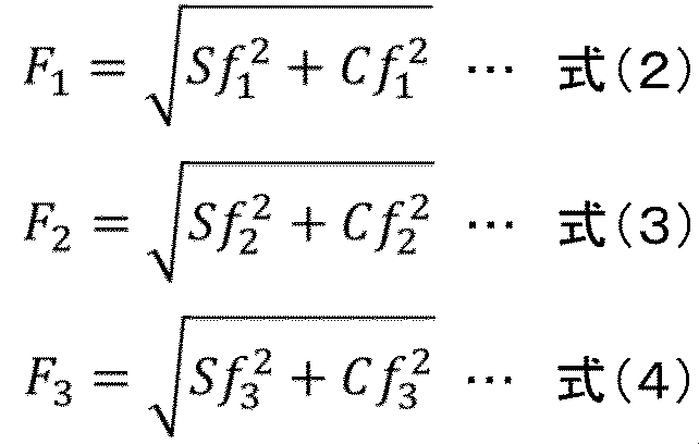


ここで、式(5)~式(7)において、μは油(液体)の粘性係数、ΔAは各位置62、61、66の面積、hは吐出側端面隙間G1の大きさと溝60Aの深さの和、ωは雌ロータ3の角速度を示している。また、式(8)~式(10)において、Δmは各位置62、61、66における油(液体)の質量、ωは雌ロータ3の角速度を示している。
ここで、溝60Aの長手方向の各位置における合力F1、F2、F3の方向として、図9に示すように、溝60Aの長手方向の各位置における雌ロータ3の半径方向R2の直交方向に対する合力F1、F2、F3の方向の角度θ(傾き)を考える。具体的には、溝60Aの他方側端部62、一方側端部61、位置66における合力F1、F2、F3の角度θ1、θ2、θ3は次の式(11)~式(13)に基づき算出可能である。
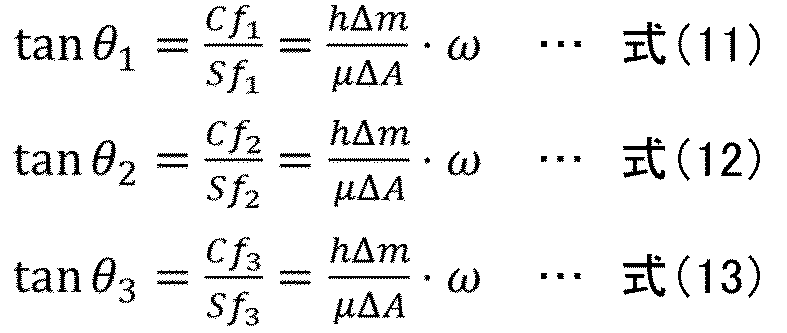
式(11)~式(13)から、合力F1の角度θ1、合力F2の角度θ2、合力F3の角度θ3は、全て同じになることがわかる。すなわち、溝60Aの長手方向の各位置における合力F1、F2、F3の雌ロータ3の半径方向R2の直交方向に対する角度θ(方向)は一定の角度になる。本実施の形態における各溝60Aは、長手方向の各位置62、61、66における法線Ng1、Ng2、Ng3が当該位置62、61、66におけるせん断力Sf1、Sf2、Sf3と遠心力Cf1、Cf2、Cf3との合力F1、F2、F3の方向と一致するように構成されている。すなわち、各溝60Aは、長手方向の各位置62、61、66における法線Ng1、Ng2、Ng3が当該位置62、61、66における雌ロータ3の周方向の接線(雌ロータ3の半径方向R2に直交する方向)に対して一定の傾きを有するように構成される。
次に、第2の実施形態に係るスクリュー圧縮機におけるケーシングの溝構造の作用及び効果について図8~図10を用いて説明する。図10は本発明の第2の実施形態に係るスクリュー圧縮機におけるケーシングの溝構造の作用を説明する図である。
本実施の形態のスクリュー圧縮機1においては、図9に示すように、ケーシング4Aの吐出側内壁面49の遮蔽領域49aに形成された各溝60A内に流入した油には、溝60Aの長手方向の各位置62、61、66において、回転する雌ロータ3の吐出側端面31cによってせん断力Sf1、Sf2、Sf3が雌ロータ3の回転方向の接線方向(雌ロータ3の径方向R2に直交する方向)であって回転方向と同じ向きに作用する。加えて、吐出側端面隙間G1における油には、雌ロータ3の吐出側端面31cによって雌ロータ3の回転方向に流動することで遠心力Cf1、Cf2、Cf3が生じる。遠心力Cf1、Cf2、Cf3は、雌ロータ3の径方向R2であって外周側の向きに作用する。
本実施の形態における各溝60Aは、図9に示すように、長手方向の各位置62、61、66における法線Ng1、Ng2、Ng3(長手方向に延在する第1側面63及び第2側面64における法線)が当該各位置62、61、66におけるせん断力Sf1、Sf2、Sf3と遠心力Cf1、Cf2、Cf3との合力F1、F2、F3の方向と一致するように構成されている。これにより、各溝60A内の油は、図10に示すように、雌ロータ3の回転に起因するせん断力Sf及び遠心力Cfによって、溝60Aの幅方向であって雌ロータ3回転方向と同じ方向に向かって流動する。溝60A内を流動する油は、溝60Aの幅方向における第1側面63Aで堰き止められることで運動エネルギ(動圧)が変換されて静圧が上昇し、最終的に、溝60Aの第1側面63Aにおける長手方向の全領域に亘って吐出側端面隙間G1(雌ロータ3側)に流出する。これにより、吐出側端面隙間G1における油の圧力は、溝60Aの第1側面63Aおける長手方向の全領域の近傍において相対的に高くなる。すなわち、吐出側端面隙間G1において、溝60Aの第1側面63Aの長手方向に沿った高圧油膜Wの形成が促進される。
また、本実施の形態においては、図10に示すように、長手方向に延在する辺同士が隣り合うように複数の溝60Aが並置されている。このため、複数の溝60Aの各第1側面63Aから昇圧された油が吐出側端面隙間G1に流出する。これにより、複数の高圧油膜Wが雌ロータ3の周方向(回転方向)に並ぶように形成される。
このように、溝60A内の油によって吐出側端面隙間G1が封止されるだけでなく、ケーシング4Aの遮蔽領域49aにおける雌ロータ3側(外径線D1側)の輪郭近傍から雄ロータ2側(ピッチ円D2側)の輪郭近傍までに亘って溝60Aの第1側面63Aから流出した油によって周囲より高圧の油膜Wが形成される。この高圧油膜Wは、アキシャル連通路G2が吐出側端面隙間G1を介して遮蔽領域49aと重なった状態において、吐出流路52(図1参照)や吐出行程の作動室Cd(図3参照)の高圧空間内の圧縮空気が遮蔽領域49a(突起部)の先端部からアキシャル連通路G2を介して吸込行程の作動室(低圧空間)に漏洩することを抑制することができる。以上により、スクリュー圧縮機1の圧縮性能と省エネ性能の向上が可能となる。
本実施の形態の溝構造(複数の溝60A)は、せん断力Sf及び遠心力Cfにより流動する油を溝幅方向における第1側面63Aで堰き止めることで動圧を静圧に変換して高圧油膜Wを形成するものであり、動圧溝の一種であると言える。各溝60Aの深さを、油に働く力のせん断力Sf及び遠心力Cfの大きさや吐出側端面隙間G1の大きさに応じて、油膜Wの圧力を最大化できる適切な値(例えば、1μm~1mmの範囲)に設定することで、アキシャル連通路G2を介した内部漏洩を更に抑制することができる。
上述した第2の実施の形態に係るスクリュー圧縮機1は、軸方向一方側に第1の吐出側端面21cを有する雄ロータ2と、軸方向一方側に第2の吐出側端面31cを有する雌ロータ3と、雄ロータ2及び雌ロータ3を噛み合った状態で回転可能に収容する収容室45を有するケーシング4とを備えている。ケーシング4は雄ロータ2の第1の吐出側端面21c及び雌ロータ3の第2の吐出側端面31cに対向する吐出側内壁面49を有し、ケーシング4の吐出側内壁面49は雄ロータ2及び雌ロータ3の回転による噛合いの変化に応じて第1の吐出側端面21c及び第2の吐出側端面31cにおいて周期的に現れ雄ロータ2及び雌ロータ3の後進面21e、31e同士によって挟まれた隙間であるアキシャル連通路G2の軌跡の少なくとも一部を遮蔽する遮蔽領域49aを有する。ケーシング4の遮蔽領域49a内に、雌ロータ3の内周側から外周側に向かって延びる長手方向を有する溝60Aが設けられている。溝60Aは、雌ロータ3の内周側から外周側に向かう長手方向が雌ロータ3の径方向R2に対して雌ロータ3の回転方向とは逆方向に傾斜するように構成されると共に、雌ロータ3の回転方向に凸の湾曲状に形成されている。さらに、溝60Aは、その長手方向の各位置62、61、66における法線Ng1、Ng2、Ng3が当該位置62、61、66における雌ロータ3の周方向の接線(雌ロータ3の径方向R2に直交する方向)に対して一定の傾きを有するように構成されている。
この構成によれば、ケーシング4Aの吐出側内壁面49に設けた溝60A内の油(液体)が雌ロータ3の回転に起因するせん断力Sf及び遠心力Cfによって溝長手方向の全体に亘って溝幅方向に流動し溝60Aの第1側面63Aに堰き止められることで静圧が上昇する。このため、吐出側端面隙間G1における偏平な三日月形状のアキシャル連通路G2の長手方向に高圧の油膜W(流体膜)を形成することができる。したがって、アキシャル連通路G2を介した圧縮気体の内部漏洩を低減することができる。
また、本実施の形態においては、溝60Aを複数有する溝群がケーシング4Aの遮蔽領域49a内に設けられており、溝群の溝60Aは溝60Aの長手方向に延在する辺同士が隣り合うように、雌ロータ3の周方向に並置されている。この構成によれば、アキシャル連通路G2の移動方向に高圧の油膜W(液体膜)を複数形成することができる。したがって、アキシャル連通路G2を介した圧縮気体の内部漏洩を更に低減することができる。したがって、アキシャル連通路G2を介した圧縮気体の内部漏洩を更に低減することができる。
また、本実施の形態における溝群の溝60Aは、雌ロータ3の回転方向の前方側に位置する溝の方が雌ロータ3の回転方向の後方側に位置する溝よりも長手方向の長さが長くなるように構成されている。この構成によれば、雌ロータ3の回転の進行と共に長手方向が長くなるアキシャル連通路G2に応じて、溝群の各溝60Aの長手方向の長さを対応させることができる。
[その他の実施の形態]
なお、上述した実施の形態においては、空気を圧縮するスクリュー圧縮機1を例に挙げて説明したが、アンモニアやCO2の冷媒など、各種気体を圧縮するスクリュー圧縮機に本発明を適用することができる。また、給油式のスクリュー圧縮機1を例に挙げて説明したが、油以外の液体が供給されるスクリュー圧縮機にも本発明を適用することができる。シーリング性能や液体膜形成の容易さ等の観点から油が好適であるが、液体膜を形成するのに十分な特性を持つ各種の液体、例えば、水で代替可能である。
なお、上述した実施の形態においては、空気を圧縮するスクリュー圧縮機1を例に挙げて説明したが、アンモニアやCO2の冷媒など、各種気体を圧縮するスクリュー圧縮機に本発明を適用することができる。また、給油式のスクリュー圧縮機1を例に挙げて説明したが、油以外の液体が供給されるスクリュー圧縮機にも本発明を適用することができる。シーリング性能や液体膜形成の容易さ等の観点から油が好適であるが、液体膜を形成するのに十分な特性を持つ各種の液体、例えば、水で代替可能である。
また、作動室内部に油等の液体が給液されない無給液式のスクリュー圧縮機に対しても同様に、各実施の形態の溝構造を適用可能である。無給液式の場合は、ロータの吐出側端面またはケーシングの吐出側内壁面の溝内に油がない代わりに圧縮空気が存在する。
一例として図6及び図7を用いて説明する。油を空気に置き換えると、溝60内に存在する空気には、相対速度を有し対向する雌ロータ3の吐出側端面31cとの摩擦によってせん断力Sfが働く。溝60内の空気は、せん断力Sfによって、溝60の長手方向の全体に亘って幅方向に流動する。溝幅方向に流動した空気は、溝60の第1側面63において堰き止められ、結果として吐出側端面隙間G1に流出する。それゆえ、吐出側端面隙間G1において、溝60の第1側面63における長手方向の全領域の近傍に、周囲に比べて相対的に空気の圧力の高い領域Wが生じる。
端面隙間を介した空気の内部漏洩量は、上流側の高圧の作動室と下流側の端面隙間の間の圧力差が大きいほど増加する特性にある。前述のように溝60を設けた場合、吐出側端面隙間G1において溝60の第1側面63における長手方向の全領域の近傍の圧力が上昇するため、吐出行程の作動室Cdと吐出側端面隙間G1との間の圧力差が、溝60が無い場合に比べて減少する。したがって、溝60を設けることで、空気の内部漏洩を抑制することが可能となる。
また、本発明は、上述した実施の形態に限られるものではなく、様々な変形例が含まれる。上記した実施形態は本発明をわかり易く説明するために詳細に説明したものであり、必ずしも説明した全ての構成を備えるものに限定されるものではない。すなわち、各実施形態の構成の一部について、他の構成の追加、削除、置換をすることも可能である。
また、上述した実施の形態においては、溝を設けたケーシング又は雄雌ロータの加工法として、例えば、成形加工や切削加工等の加工法を用いることが可能である。しかし、溝を設けるケーシングまたはロータ若しくはその両方を三次元造型機によって製造することも可能である。三次元造型機に利用するデータは、CADやCGソフトウェア又は3Dスキャナで生成した3DデータをCAMによってNCデータに加工することで生成する。該データを3次元造形機に任意の方法で入力することで造形を行う。なお、CAD/CAMソフトウェアによって、3Dデータから直接NCデータを生成しても良い。
1…スクリュー圧縮機、 2…雄ロータ、 3…雌ロータ、 4、4A…ケーシング、 21c…吐出側端面(第1の吐出側端面)、 21e…後進面、 31c…吐出側端面(第2の吐出側端面)、 31e…後進面、 45…収容室、 49…吐出側内壁面、 49a…遮蔽領域、 60、60A…溝、 61、62、66…長手方向の位置、 Ng1、Ng2、Ng3…法線、 G2…アキシャル連通路
Claims (7)
- 軸方向一方側に第1の吐出側端面を有する雄ロータと、
軸方向一方側に第2の吐出側端面を有する雌ロータと、
前記雄ロータ及び前記雌ロータを噛み合った状態で回転可能に収容する収容室を有するケーシングとを備え、
前記ケーシングは、前記雄ロータの前記第1の吐出側端面及び前記雌ロータの前記第2の吐出側端面に対向する吐出側内壁面を有し、
前記ケーシングの前記吐出側内壁面は、前記雄ロータ及び前記雌ロータの回転による噛合い状態の変化に応じて前記第1の吐出側端面及び前記第2の吐出側端面において周期的に現れ前記雄ロータ及び前記雌ロータの後進面同士によって挟まれた隙間であるアキシャル連通路の軌跡の少なくとも一部を遮蔽する遮蔽領域を有し、
前記ケーシングの前記遮蔽領域内に、長手方向を有する溝が設けられ、
前記溝は、前記長手方向の各位置における法線が当該位置における前記雌ロータの周方向の接線と一致するように構成されている
ことを特徴とするスクリュー圧縮機。 - 請求項1に記載のスクリュー圧縮機において、
前記溝は、前記雌ロータの径方向に沿って直線状に延在するように構成されている
ことを特徴とするスクリュー圧縮機。 - 請求項1に記載のスクリュー圧縮機において、
前記溝を複数有する溝群が前記ケーシングの前記遮蔽領域内に設けられ、
前記溝群の前記溝は、前記長手方向に延在する辺同士が隣り合うように、前記雌ロータの周方向に並置されている
ことを特徴とするスクリュー圧縮機。 - 請求項3に記載のスクリュー圧縮機において、
前記溝群の前記溝は、前記雌ロータの回転方向の前方側に位置する溝の方が前記雌ロータの回転方向の後方側に位置する溝よりも前記長手方向の長さが長くなるように構成されている
ことを特徴とするスクリュー圧縮機。 - 軸方向一方側に第1の吐出側端面を有する雄ロータと、
軸方向一方側に第2の吐出側端面を有する雌ロータと、
前記雄ロータ及び前記雌ロータを噛み合った状態で回転可能に収容する収容室を有するケーシングとを備え、
前記ケーシングは、前記雄ロータの前記第1の吐出側端面及び前記雌ロータの前記第2の吐出側端面に対向する吐出側内壁面を有し、
前記ケーシングの前記吐出側内壁面は、前記雄ロータ及び前記雌ロータの回転による噛合い状態の変化に応じて前記第1の吐出側端面及び前記第2の吐出側端面において周期的に現れ前記雄ロータ及び前記雌ロータの後進面同士によって挟まれた隙間であるアキシャル連通路の軌跡の少なくとも一部を遮蔽する遮蔽領域を有し、
前記ケーシングの前記遮蔽領域内に、前記雌ロータの内周側から外周側に向かって延びる長手方向を有する溝が設けられ、
前記溝は、前記雌ロータの内周側から外周側に向かう長手方向が前記雌ロータの径方向に対して前記雌ロータの回転方向とは逆方向に傾斜するように構成されると共に、前記雌ロータの回転方向に凸の湾曲状に形成され、
前記溝は、前記長手方向の各位置における法線が当該位置における前記雌ロータの周方向の接線に対して一定の傾きを有するように構成されている
ことを特徴とするスクリュー圧縮機。 - 請求項5に記載のスクリュー圧縮機において、
前記溝を複数有する溝群が前記ケーシングの前記遮蔽領域内に設けられ、
前記溝群の前記溝は、前記長手方向に延在する辺同士が隣り合うように、前記雌ロータの周方向に並置されている
ことを特徴とするスクリュー圧縮機。 - 請求項6に記載のスクリュー圧縮機において、
前記溝群の前記溝は、前記雌ロータの回転方向の前方側に位置する溝の方が前記雌ロータの回転方向の後方側に位置する溝よりも前記長手方向の長さが長くなるように構成されている
ことを特徴とするスクリュー圧縮機。
Applications Claiming Priority (2)
| Application Number | Priority Date | Filing Date | Title |
|---|---|---|---|
| JP2022098105A JP7739230B2 (ja) | 2022-06-17 | 2022-06-17 | スクリュー圧縮機 |
| JP2022-098105 | 2022-06-17 |
Publications (1)
| Publication Number | Publication Date |
|---|---|
| WO2023243171A1 true WO2023243171A1 (ja) | 2023-12-21 |
Family
ID=89192548
Family Applications (1)
| Application Number | Title | Priority Date | Filing Date |
|---|---|---|---|
| PCT/JP2023/010824 Ceased WO2023243171A1 (ja) | 2022-06-17 | 2023-03-20 | スクリュー圧縮機 |
Country Status (2)
| Country | Link |
|---|---|
| JP (1) | JP7739230B2 (ja) |
| WO (1) | WO2023243171A1 (ja) |
Cited By (1)
| Publication number | Priority date | Publication date | Assignee | Title |
|---|---|---|---|---|
| US20240052830A1 (en) * | 2020-12-18 | 2024-02-15 | Hitachi Industrial Equipment Systems Co., Ltd. | Screw Compressor |
Citations (3)
| Publication number | Priority date | Publication date | Assignee | Title |
|---|---|---|---|---|
| JPS49118811U (ja) * | 1973-02-09 | 1974-10-11 | ||
| JPS52134110U (ja) * | 1976-04-07 | 1977-10-12 | ||
| JP2006226160A (ja) * | 2005-02-16 | 2006-08-31 | Hokuetsu Kogyo Co Ltd | 油冷式スクリュ圧縮機 |
-
2022
- 2022-06-17 JP JP2022098105A patent/JP7739230B2/ja active Active
-
2023
- 2023-03-20 WO PCT/JP2023/010824 patent/WO2023243171A1/ja not_active Ceased
Patent Citations (3)
| Publication number | Priority date | Publication date | Assignee | Title |
|---|---|---|---|---|
| JPS49118811U (ja) * | 1973-02-09 | 1974-10-11 | ||
| JPS52134110U (ja) * | 1976-04-07 | 1977-10-12 | ||
| JP2006226160A (ja) * | 2005-02-16 | 2006-08-31 | Hokuetsu Kogyo Co Ltd | 油冷式スクリュ圧縮機 |
Cited By (2)
| Publication number | Priority date | Publication date | Assignee | Title |
|---|---|---|---|---|
| US20240052830A1 (en) * | 2020-12-18 | 2024-02-15 | Hitachi Industrial Equipment Systems Co., Ltd. | Screw Compressor |
| US12110889B2 (en) * | 2020-12-18 | 2024-10-08 | Hitachi Industrial Equipment Systems Co., Ltd. | Screw compressor |
Also Published As
| Publication number | Publication date |
|---|---|
| JP2023184136A (ja) | 2023-12-28 |
| JP7739230B2 (ja) | 2025-09-16 |
Similar Documents
| Publication | Publication Date | Title |
|---|---|---|
| JP6986117B2 (ja) | 流体機械 | |
| CN104047852B (zh) | 螺杆压缩机 | |
| JP6899288B2 (ja) | スクリュー圧縮機 | |
| WO2023243171A1 (ja) | スクリュー圧縮機 | |
| US11009025B2 (en) | Oil-cooled screw compressor | |
| CN103807178A (zh) | 螺杆式压缩机 | |
| JP6677515B2 (ja) | オイルフリースクリュ圧縮機 | |
| WO1992009807A1 (fr) | Compresseur a vis du type a jet de fluide | |
| JP2024507622A (ja) | ロータ・アセンブリ、圧縮機及びエア・コンディショナ | |
| CN102667162A (zh) | 叶片式压缩机的润滑油供给结构 | |
| EP0211514A1 (en) | Rotary machine having screw rotor assembly | |
| US6659746B2 (en) | Shaft seal structure of vacuum pumps | |
| JP7490549B2 (ja) | スクリュー圧縮機 | |
| CN218266344U (zh) | 一种无油螺杆鼓风机的组合式密封装置 | |
| JP4321206B2 (ja) | 気体圧縮装置 | |
| JP2846065B2 (ja) | 液注入式スクリュ流体機械 | |
| WO2025041447A1 (ja) | スクリュー圧縮機 | |
| JPS5996496A (ja) | ベ−ン圧縮機 | |
| US20260028987A1 (en) | Screw Fluid Machine | |
| EP1944513A1 (en) | Liquid injection type screw compressor | |
| WO1998059171A1 (en) | Gear pump | |
| CN111441945B (zh) | 真空泵 | |
| JP2025181127A (ja) | ギヤポンプ装置 | |
| CN121100230A (zh) | 外啮合齿轮泵 | |
| JPH03194183A (ja) | 液噴射式スクリュ流体機械 |
Legal Events
| Date | Code | Title | Description |
|---|---|---|---|
| 121 | Ep: the epo has been informed by wipo that ep was designated in this application |
Ref document number: 23823475 Country of ref document: EP Kind code of ref document: A1 |
|
| NENP | Non-entry into the national phase |
Ref country code: DE |
|
| 122 | Ep: pct application non-entry in european phase |
Ref document number: 23823475 Country of ref document: EP Kind code of ref document: A1 |