WO2023243161A1 - 回転電機及びこれを備えた車両駆動装置 - Google Patents
回転電機及びこれを備えた車両駆動装置 Download PDFInfo
- Publication number
- WO2023243161A1 WO2023243161A1 PCT/JP2023/008776 JP2023008776W WO2023243161A1 WO 2023243161 A1 WO2023243161 A1 WO 2023243161A1 JP 2023008776 W JP2023008776 W JP 2023008776W WO 2023243161 A1 WO2023243161 A1 WO 2023243161A1
- Authority
- WO
- WIPO (PCT)
- Prior art keywords
- flow path
- rotor
- shaft
- end plate
- electric machine
- Prior art date
Links
Images


Classifications
-
- H—ELECTRICITY
- H02—GENERATION; CONVERSION OR DISTRIBUTION OF ELECTRIC POWER
- H02K—DYNAMO-ELECTRIC MACHINES
- H02K9/00—Arrangements for cooling or ventilating
- H02K9/19—Arrangements for cooling or ventilating for machines with closed casing and closed-circuit cooling using a liquid cooling medium, e.g. oil
-
- H—ELECTRICITY
- H02—GENERATION; CONVERSION OR DISTRIBUTION OF ELECTRIC POWER
- H02K—DYNAMO-ELECTRIC MACHINES
- H02K1/00—Details of the magnetic circuit
- H02K1/06—Details of the magnetic circuit characterised by the shape, form or construction
- H02K1/22—Rotating parts of the magnetic circuit
- H02K1/32—Rotating parts of the magnetic circuit with channels or ducts for flow of cooling medium
-
- H—ELECTRICITY
- H02—GENERATION; CONVERSION OR DISTRIBUTION OF ELECTRIC POWER
- H02K—DYNAMO-ELECTRIC MACHINES
- H02K1/00—Details of the magnetic circuit
- H02K1/06—Details of the magnetic circuit characterised by the shape, form or construction
- H02K1/22—Rotating parts of the magnetic circuit
- H02K1/27—Rotor cores with permanent magnets
- H02K1/2706—Inner rotors
- H02K1/272—Inner rotors the magnetisation axis of the magnets being perpendicular to the rotor axis
- H02K1/274—Inner rotors the magnetisation axis of the magnets being perpendicular to the rotor axis the rotor consisting of two or more circumferentially positioned magnets
- H02K1/2753—Inner rotors the magnetisation axis of the magnets being perpendicular to the rotor axis the rotor consisting of two or more circumferentially positioned magnets the rotor consisting of magnets or groups of magnets arranged with alternating polarity
- H02K1/276—Magnets embedded in the magnetic core, e.g. interior permanent magnets [IPM]
-
- H—ELECTRICITY
- H02—GENERATION; CONVERSION OR DISTRIBUTION OF ELECTRIC POWER
- H02K—DYNAMO-ELECTRIC MACHINES
- H02K1/00—Details of the magnetic circuit
- H02K1/06—Details of the magnetic circuit characterised by the shape, form or construction
- H02K1/22—Rotating parts of the magnetic circuit
- H02K1/28—Means for mounting or fastening rotating magnetic parts on to, or to, the rotor structures
- H02K1/30—Means for mounting or fastening rotating magnetic parts on to, or to, the rotor structures using intermediate parts, e.g. spiders
-
- H—ELECTRICITY
- H02—GENERATION; CONVERSION OR DISTRIBUTION OF ELECTRIC POWER
- H02K—DYNAMO-ELECTRIC MACHINES
- H02K21/00—Synchronous motors having permanent magnets; Synchronous generators having permanent magnets
- H02K21/12—Synchronous motors having permanent magnets; Synchronous generators having permanent magnets with stationary armatures and rotating magnets
- H02K21/14—Synchronous motors having permanent magnets; Synchronous generators having permanent magnets with stationary armatures and rotating magnets with magnets rotating within the armatures
-
- H—ELECTRICITY
- H02—GENERATION; CONVERSION OR DISTRIBUTION OF ELECTRIC POWER
- H02K—DYNAMO-ELECTRIC MACHINES
- H02K7/00—Arrangements for handling mechanical energy structurally associated with dynamo-electric machines, e.g. structural association with mechanical driving motors or auxiliary dynamo-electric machines
- H02K7/003—Couplings; Details of shafts
-
- H—ELECTRICITY
- H02—GENERATION; CONVERSION OR DISTRIBUTION OF ELECTRIC POWER
- H02K—DYNAMO-ELECTRIC MACHINES
- H02K7/00—Arrangements for handling mechanical energy structurally associated with dynamo-electric machines, e.g. structural association with mechanical driving motors or auxiliary dynamo-electric machines
- H02K7/10—Structural association with clutches, brakes, gears, pulleys or mechanical starters
- H02K7/116—Structural association with clutches, brakes, gears, pulleys or mechanical starters with gears
-
- H—ELECTRICITY
- H02—GENERATION; CONVERSION OR DISTRIBUTION OF ELECTRIC POWER
- H02K—DYNAMO-ELECTRIC MACHINES
- H02K9/00—Arrangements for cooling or ventilating
- H02K9/19—Arrangements for cooling or ventilating for machines with closed casing and closed-circuit cooling using a liquid cooling medium, e.g. oil
- H02K9/193—Arrangements for cooling or ventilating for machines with closed casing and closed-circuit cooling using a liquid cooling medium, e.g. oil with provision for replenishing the cooling medium; with means for preventing leakage of the cooling medium
Definitions
- the present invention relates to a rotating electric machine and a vehicle drive device equipped with the same.
- Patent Document 1 As a technique for cooling a rotating electric machine, there are techniques described in Patent Documents 1 to 3, for example.
- Patent Document 1 an oil hole is provided in the center of the shaft, and a supply hole extending toward the outer circumferential side of the shaft is passed through the oil hole.
- the rotor built into the shaft is provided with a cooling oil passage that extends through the cooling oil passage in the axial direction, and a receiver that covers the opening of the cooling oil passage at the end of the cooling oil passage.
- the receiver receives the lubricating oil discharged from the supply hole to the atmosphere, cools the rotor by flowing the lubricating oil into the cooling oil passage, and then discharges the lubricating oil from the cooling oil passage.
- the coil ends of the stator are cooled.
- an oil passage is formed that penetrates the rotor core in the axial direction.
- One end of the rotor core is provided with an end plate having an oil supply hole that communicates with the oil passage and an oil discharge hole that projects oil into the coil.
- the cross-sectional area of the oil passage is made larger on the downstream side of the oil flow than on the upstream side.
- the other end of the rotor core is provided with an end plate having an oil discharge hole communicating with an oil passage having an enlarged cross-sectional area.
- the coil is cooled by the oil discharged from the oil discharge hole, and the rotor is cooled by the oil flowing through the oil passage.
- a hole is formed in the rotating shaft, passing through the rotating shaft toward the outside in the radial direction and communicating with the shaft flow path.
- An end plate is provided at an axial end of the rotating core, a groove is formed in the end plate, and a refrigerant passage is formed between the wall surface of the end plate and the end surface of the rotating core. This refrigerant passage communicates with the hole in the shaft.
- a first discharge hole is provided in the middle of the refrigerant passage, and a second discharge hole is provided at the end of the refrigerant passage. The oil that has flowed through the shaft channel, holes, and refrigerant passage is discharged from the first discharge hole and the second discharge hole to cool the coil end.
- Patent Document 1 In the technology described in Patent Document 1, a rotor rotates, a receiver receives lubricating oil discharged from a supply hole by centrifugal force, cools the rotor by flowing the lubricating oil into a cooling oil passage, and then cools the rotor.
- the lubricating oil is discharged from the supply hole to cool the stator coil end, but since the lubricating oil discharged from the supply hole is released to the atmosphere, even if the rotor speed increases, the centrifugal It is not possible to increase the flow rate of lubricating oil flowing through the cooling oil passage using force. For this reason, the technique described in Patent Document 1 has a problem in that the magnets disposed on the rotor cannot be sufficiently cooled as the rotational speed of the rotor increases.
- An object of the present invention is to provide a rotating electric machine that can cool a stator coil and a rotor magnet according to the rotational speed of the rotor, and a vehicle drive system equipped with the same.
- the present invention provides a rotating electric machine including a rotor in which magnets are disposed in a rotor core, and a stator disposed on the outer diameter side of the rotor, the stator being disposed on the inner circumference side of the rotor.
- a rotating electric machine including a rotor in which magnets are disposed in a rotor core, and a stator disposed on the outer diameter side of the rotor, the stator being disposed on the inner circumference side of the rotor.
- a rotor shaft a shaft passage through which a refrigerant flows is provided inside the rotor shaft, and the rotor extends radially outwardly of the rotor shaft and opens radially outwardly.
- a first flow passage having a first discharge port
- a second flow path having a second discharge port opened by the shaft, the first flow path and the second flow path are connected to the shaft flow path, and the second discharge port is connected to the first discharge port. It is characterized by
- FIG. 1 is a schematic configuration diagram of an electric vehicle according to an embodiment of the present invention.
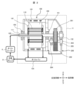
- 1 is a schematic configuration diagram of a system for cooling a vehicle drive device according to an embodiment of the present invention.
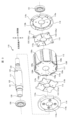
- FIG. 2 is an exploded perspective view of the rotor 110 viewed from the opposite load side.
- FIG. 2 is an exploded perspective view of the rotor 110 viewed from the load side. It is a top view of a 1st end plate and a 3rd end plate seen from the side which faces a 2nd end plate and a 4th end plate side.
- FIG. 3 is a plan view of the first end plate and the third end plate as seen from the side facing the rotor core.
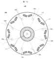
- FIG. 3 is a cross-sectional view of the rotor taken in a direction perpendicular to the axial direction.
- FIG. 2 is a cross-sectional perspective view taken along the axial direction of the rotor 110 according to the first embodiment of the present invention.
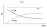
- FIG. 3 is a cross-sectional view of the upper half of the rotor 110 taken along the axial direction. It is a figure showing the relationship between the flow volume of the 1st flow path and the 2nd flow path according to a change of rotation speed.
- FIG. 3 is a cross-sectional view of a rotor according to a second embodiment of the present invention taken in a direction perpendicular to the axial direction.
- FIG. 7 is a cross-sectional view of the upper half of a rotor 110 according to a third embodiment of the present invention, taken along the axial direction.
- FIG. 7 is a cross-sectional perspective view taken along the axial direction of a rotor 110 according to a fourth embodiment of the present invention.
- FIG. 7 is a cross-sectional perspective view taken along the axial direction of a rotor 110 according to a fifth embodiment of the present invention.
- FIG. 7 is a cross-sectional perspective view taken along the axial direction of a rotor 110 according to a sixth embodiment of the present invention.
- the various components of the present invention do not necessarily have to exist independently, and one component may be made up of multiple members, multiple components may be made of one member, or a certain component may be different from each other. It is allowed that a part of a certain component overlaps with a part of another component, etc.
- FIG. 1 is a schematic configuration diagram of an electric vehicle according to Embodiment 1 of the present invention.
- a vehicle drive device 3 for driving wheels 2 is mounted on a vehicle body 1 .
- the vehicle drive device 3 is a drive unit in which devices such as a rotating electric machine and an inverter are integrated.
- An oil cooler 4 is connected to the vehicle drive device 3 via a pipe 7.
- the piping 7 is equipped with a refrigerant pump 8 that pumps the first refrigerant, and flows the refrigerant to devices in the vehicle drive device 3 to cool these devices.
- a chiller 6 is connected to the oil cooler 4 via a pipe 5, and a second refrigerant flows through the oil cooler 4, the pipe 5, and the chiller 6. Heat exchange is performed in the oil cooler 4, and the heated first refrigerant is cooled by the second refrigerant.
- the second refrigerant is pumped by a pump 9 provided in the pipe 5 and sent to the chiller 6. In the chiller 6, the heated second refrigerant is cooled by the wind generated when the vehicle is running. The cooled refrigerant is sent to the oil cooler 4 again.
- FIG. 2 is a schematic configuration diagram of a system for cooling a vehicle drive device according to Embodiment 1 of the present invention.
- the side where the vehicle drive device 3 transmits driving force is the "load side", the opposite side is the “counter-load side", the upward direction is the “upper/upper side”, and the downward direction is the “lower side”. ⁇ Defined as “lower side”.
- the direction along the shaft is “axial direction”
- the circumference around the rotor shaft is “circumferential direction”
- the radial direction (radial direction) when the shaft is the center is “radial direction”
- the direction perpendicular to the horizontal line. is defined as the vertical direction.
- the vehicle drive device 3 includes a rotating electrical machine 100, a reduction gear 200 that transmits the driving force of the rotating electrical machine 100, and an inverter (not shown).
- the rotating electrical machine 100 includes a rotor 110 and a stator 140 disposed on the outer diameter side of the rotor 110. Rotor 110 and stator 140 are housed within housing 101.
- a rotor shaft 111 is provided on the inner peripheral side of the rotor 110 and is rotatably supported by bearings 150, 151, and 152.
- a drive gear 201 constituting a reduction gear 200
- a driven gear 202 that meshes with the drive gear 201 and transmits driving force to the drive gear 201
- a driven gear provided in the driven gear 202 are provided. It includes a shaft 203 and bearings 204 and 205 that pivotally support the driven gear shaft 203.
- the stator 140 includes a plurality of starter coils 141 inserted into slots formed in the stator core.
- the inside of the rotor shaft 111 is hollow, and a shaft flow path 120 through which the refrigerant flows is formed.
- the refrigerant flowing through the shaft flow path cools the stator coil 141 and the rotor 110, and then falls into the oil pan 154 disposed at the bottom of the rotating electrical machine 100.
- the refrigerant that has fallen into the oil pan 154 and is collected is pumped by the refrigerant pump 8 and sent to the oil cooler 4 and the shaft flow path 120.
- the stator coil 141 and rotor 110 are cooled, they fall into the oil pan 154 again.
- the stator coil 141 and rotor 110 are cooled by circulating the refrigerant in this manner.
- FIG. 3 is an exploded perspective view of the rotor 110 seen from the opposite load side.
- FIG. 4 is an exploded perspective view of the rotor 110 viewed from the load side.
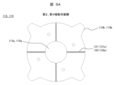
- FIG. 5A is a plan view of the first end plate and the third end plate viewed from the side facing the second end plate and the fourth end plate.
- FIG. 5B is a plan view of the first end plate and the third end plate viewed from the side facing the rotor core.
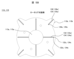
- FIG. 6 is a cross-sectional view of the rotor taken in a direction perpendicular to the axial direction.
- the rotor 110 includes a rotor core 112 configured by laminating a plurality of steel plates, a first end plate 113 disposed at one axial end (anti-load side) of the rotor core 112, and one of the first end plates 113. a second end plate 114 disposed on the axially outer side (counter-load side) of the rotor core 112; a third end plate 115 disposed on the other axial end (load side) of the rotor core 112; and a fourth end plate 116 disposed on the other axially outer side (load side).
- the first end plate 113 is arranged so as to be sandwiched between the second end plate 114 and the rotor core 112, and the third end plate 115 is arranged so as to be sandwiched between the fourth end plate 116 and the rotor core 112.
- first shaft passage hole 121 that communicates with the shaft passage 120
- second shaft that communicates with the shaft passage 120 and is arranged adjacent to the first shaft passage hole 121.
- a flow path hole 122 a third shaft flow path hole 123 that communicates with the shaft flow path 120
- a fourth shaft flow path hole that communicates with the shaft flow path 120 and is arranged adjacent to the third shaft flow path hole 123 124 are provided.
- the first shaft passage hole 121 and the second shaft passage hole 122 are arranged at the same position in the circumferential direction of the rotor shaft 111, and the third shaft passage hole 123 and the fourth shaft passage hole 124 are arranged at the same position in the circumferential direction of the rotor shaft 111. They are arranged at the same position in the circumferential direction of the shaft 111.
- the first shaft passage hole 121 (second shaft passage hole 122) and the third shaft passage hole 123 (fourth shaft passage hole 124) are arranged so as to be shifted in the circumferential direction of the rotor shaft 111. Further, a plurality of first to fourth shaft passage holes 121 to 124 are provided in the circumferential direction of the rotor shaft 111.
- An insertion hole 113a penetrating in the axial direction into which the rotor shaft 111 is inserted is formed in the center of the first end plate 113.
- a plurality of first grooves 131 are formed on the outer side (second end plate 114 side) of the first end plate 113, and extend radially outward from the insertion hole 113a.
- a plurality of second grooves 132 are formed on the inner surface (rotor core 112 side) of the first end plate 113, extending radially outward from the insertion hole 113a.
- the first end plate 113 is formed with a plurality of protrusions 113b that protrude outward in the radial direction.
- a plurality of sixth grooves 136 are formed on the surface of the protrusion 113b on the inner side of the first end plate 113 (rotor core 112 side), extending radially outward in the radial direction.
- the first end plate 113 is arranged at a position overlapping the first shaft passage hole 121 and the second shaft passage hole 122 formed in the rotor shaft 111.
- the first groove portion 131 communicates with the first shaft passage hole 121, and the second groove portion 132 communicates with the second shaft passage hole 122.
- the first groove portion 131 When the first end plate 113 contacts the second end plate 114, the first groove portion 131 is covered and a first flow path 131a through which the refrigerant flows is formed. That is, the first groove portion 131 is formed between the first end plate 113 and the second end plate 114.
- the first flow path 131a is formed to penetrate in the radial direction from the insertion hole 113a to the outside in the radial direction.
- the second groove portion 132 When the first end plate 113 comes into contact with the rotor core 112, the second groove portion 132 is covered, and an anti-load side second flow path 132a (second flow path) through which the refrigerant flows is formed. Further, when the first end plate 113 comes into contact with the rotor core 112, the sixth groove portion 136 is covered, and an anti-load side fourth flow path 136a (fourth flow path) through which the refrigerant flows is formed. That is, the counter-load side second flow path 132a, which is a part of the second flow path, and the counter-load side fourth flow path 136a, which is a part of the fourth flow path, are formed by the first end plate 113 and the rotor core 112. Formed by being sandwiched.
- the anti-load side second flow path 132a (second flow path) penetrates the insertion hole 113a on the inside in the radial direction, but is dammed on the outside in the radial direction by a damming part 132s (FIG. 5B).
- a radially outer end 132e of the second opposite-load flow path 132a (second flow path) is connected to the rotor core flow path 130.
- the anti-load side fourth flow path 136a (fourth flow path) is penetrated at the radially outer side, the radially inner side is dammed.
- a radially inner end 136e of the fourth counter-load flow path 136a (fourth flow path) is connected to the rotor core flow path 130.
- a fitting notch 114c serving as an outlet is formed.
- a first flow path 131a, a second flow path 132a (second flow path) on the opposite load side, and a second flow path 132a (second flow path) on the opposite load side are combined.
- Four channels 136a (fourth channels) are formed, and by combining these with the rotor shaft 111, the first channel 131a and the first shaft channel hole 121 communicate with each other, and the second channel 132a on the opposite load side (the second flow path) and the second shaft flow path hole 122 communicate with each other.
- An insertion hole 115a penetrating in the axial direction into which the rotor shaft 111 is inserted is formed in the center of the third end plate 115.
- a plurality of third grooves 133 are formed on the outer surface (on the fourth end plate 116 side) of the third end plate 115, and extend radially outward from the insertion hole 115a.
- a plurality of fourth grooves 134 are formed on the inner surface (rotor core 112 side) of the third end plate 115, and extend radially outward from the insertion hole 115a.
- the third end plate 115 is formed with a plurality of protrusions 115b that protrude radially outward.
- a plurality of fifth grooves 135 are formed on the surface of the protruding portion 115b on the inner side of the third end plate 115 (on the rotor core 112 side), extending radially outward in the radial direction.
- the third end plate 115 is arranged at a position overlapping the third shaft passage hole 123 and the fourth shaft passage hole 124 formed in the rotor shaft 111.
- the third groove portion 133 communicates with the third shaft passage hole 123, and the fourth groove portion 134 communicates with the fourth shaft passage hole 124.
- the third groove portion 133 When the third end plate 115 comes into contact with the fourth end plate 116, the third groove portion 133 is covered and a third flow path 133a through which the refrigerant flows is formed. That is, the third groove portion 133 is formed between the third end plate 115 and the fourth end plate 116.
- the third flow path 133a is formed to penetrate in the radial direction from the insertion hole 113a to the outside in the radial direction.
- the fourth groove portion 134 When the third end plate 115 comes into contact with the rotor core 112, the fourth groove portion 134 is covered, and a load-side fourth flow path 134a (fourth flow path) through which the refrigerant flows is formed. Further, when the third end plate 115 comes into contact with the rotor core 112, the fifth groove portion 135 is covered, and a load-side second flow path 135a (second flow path) through which the refrigerant flows is formed. That is, the load-side fourth flow path 134a, which is part of the fourth flow path, and the load-side second flow path 135a, which is part of the second flow path, are sandwiched between the third end plate 115 and the rotor core 112. It is formed by
- the load-side fourth flow path 134a (fourth flow path) penetrates the insertion hole 115a on the radially inner side, but is dammed on the radially outer side by a dam stop portion 134s (FIG. 5B).
- a radially outer end 134e of the load-side fourth flow path 134a (second flow path) is connected to the rotor core flow path 130.
- the load-side second flow path 135a (second flow path) passes through on the radially outer side, but is dammed on the radially inner side.
- a radially inner end 135e of the load-side second flow path 135a (second flow path) is connected to the rotor core flow path 130.
- a fitting notch 116c serving as an outlet is formed.
- a third flow path 133a and a load-side fourth flow path 134a (fourth flow path) are formed.
- the third flow path 133a and the third shaft flow path hole 123 communicate with each other
- the load side fourth flow path 134a (fourth flow path) and the fourth shaft flow path hole 124 communicate with each other.
- connection portions of the first flow path and the second flow path with the shaft flow path 120 are located on one side of the rotor shaft 111, and the connection portions of the third flow path and the shaft flow path 120 of the fourth flow path are located on one side of the rotor shaft 111. is on the other side of the rotor shaft 111.
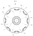
- a plurality of permanent magnets 117 are arranged in the rotor core 112.
- the permanent magnet 117 has N poles and S poles arranged alternately in the circumferential direction. Further, the permanent magnet 117 arranged at one pole is divided.
- the rotor core 112 includes an axially penetrating insertion hole 112a into which the rotor shaft 111 is inserted, and a plurality of axially penetrating rotor core channels forming part of the second and fourth channels through which the refrigerant flows. 130 (rotor core channels 130a to 130h) are formed.
- the plurality of rotor core channels 130a to 130h are arranged so as to maintain magnetic pole symmetry or magnetic pole pair symmetry. In this embodiment, the plurality of rotor core channels 130a to 130h are arranged at intervals of 45° in the circumferential direction.
- the plurality of rotor core flow paths 130a to 130h constituting the second flow path and the fourth flow path are arranged so as to maintain magnetic pole symmetry or magnetic pole pair symmetry, power running and regeneration This makes it possible to suppress differences in motor characteristics.
- rotor core flow passages 130a to 130d each have an anti-load side second flow passage 132a (second flow passage) at a position of a radially outer end 132e formed in the first end plate 113.
- the rotor core channels 130e to 130h each communicate with a fourth counter-load channel 136a (fourth channel) at a radially inner end 136e formed in the first end plate 113. That is, rotor core flow paths 130a to 130d become second flow paths, and rotor core flow paths 130e to 130h become fourth flow paths.
- each of the rotor core flow paths 130a to 130d is located at a position of a radially inner end 135e formed in the third end plate 115 at a load side second flow path 135a (second flow path ), and each of the rotor core flow paths 130e to 130h communicates with a load-side fourth flow path 134a (fourth flow path) at a position of a radially outer end 134e formed in the third end plate 115.
- the second flow path of this embodiment extends radially outward of the rotor shaft 111 through an anti-load side second flow path 132a and is connected to the rotor core flow paths 130a to 130d.
- the second discharge port is connected to the load-side second flow path 135a, extends radially outward, and has a second discharge port opened radially outward.
- the fourth flow path of this embodiment extends radially outward of the rotor shaft 111 through a load-side fourth flow path 134a and is connected to the rotor core flow paths 130e to 130h. After extending in the axial direction inside the rotor core 112, it has a fourth discharge port that is connected to the counter-load side fourth flow path 136a, extends radially outward, and opens radially outward.
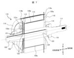
- FIG. 7 is a cross-sectional perspective view taken along the axial direction of the rotor 110 according to the first embodiment of the present invention.
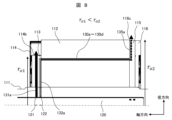
- FIG. 8 is a cross-sectional view of the upper half of the rotor 110 taken along the axial direction.
- the rotor shaft 111 is open at one axial end (counter-load side) and solid at the other end (load side).
- a refrigerant pump 8 is connected to an opening at one end of the rotor shaft 111 via an oil cooler 4 (FIG. 2).
- an oil cooler 4 FIG. 2.
- the refrigerant discharged radially outward from the first shaft passage hole 121 passes through the first passage 131a and is discharged from the notch 114b (first discharge port).
- the refrigerant discharged from the notch 114b hits the stator coil 141 and cools the stator coil 141.
- the refrigerant discharged radially outward from the second shaft flow path hole 122 includes an anti-load side second flow path 132a forming a second flow path, a rotor core flow path 130 (130a, 130c, 130e, 130g), It passes through the load-side second flow path 135a and is discharged from the fitting notch 116c (second discharge port).
- the refrigerant discharged from the fitting notch 116c hits the stator coil 141 and cools the stator coil 141. Furthermore, since the refrigerant flowing through the second flow path flows inside the rotor core 112, it cools the permanent magnets 117 disposed in the rotor core 112.
- the refrigerant discharged radially outward from the third shaft passage hole 123 passes through the third passage 133a and is discharged from the notch 116b (third discharge port).
- the refrigerant discharged from the notch 116b hits the stator coil 141 and cools the stator coil 141.
- the refrigerant discharged radially outward from the fourth shaft passage hole 124 flows through the load side fourth passage 134a forming the fourth passage, the rotor core passage 130 (130b, 130d, 130f, 130h), and the opposite side. It passes through the load-side fourth flow path 136a and is discharged from the fitting notch 114c (fourth discharge port).
- the refrigerant discharged from the fitting notch 114c hits the stator coil 141 and cools the stator coil 141. Furthermore, since the refrigerant flowing through the fourth flow path flows inside the rotor core 112, it cools the permanent magnets 117 disposed in the rotor core 112.
- the flow in the rotor core flow paths 130a to 130d forming the second flow path and the rotor core flow paths 130e to 130h forming the fourth flow path are arranged such that the axial flows are opposite to each other and alternate in the circumferential direction. There is.
- a plurality (four each) of the first flow path, the second flow path, and the third flow path and the fourth flow path are arranged at equal intervals in the circumferential direction. Further, the numbers of the first flow passages and the second flow passages are the same on one side and the other side in the axial direction, and the numbers of the third flow passages and the fourth flow passages are the same on one side and the other side in the axial direction.
- the first flow path and the third flow path are arranged so as not to overlap when viewed from the axial direction, and are arranged at a 45° offset in the circumferential direction.
- the second flow path and the fourth flow path are arranged so as not to overlap when viewed from the axial direction, and are arranged at a 45° offset in the circumferential direction.
- the rotational speed of rotating electric machines used to drive vehicles etc. changes depending on the load. Since a large motor torque is required during low speed rotation, the current flowing through the stator coil increases, and the amount of heat generated by the stator coil increases. On the other hand, during high-speed rotation, eddy current loss increases and the temperature of the permanent magnet increases. That is, it is preferable that the rotating electrical machine mainly cools the stator coil during low-speed rotation, and mainly cools the permanent magnets during high-speed rotation.
- the fitting notch 116c (second discharge port) serving as the discharge port of the second flow path is radially outward from the notch 114b (first discharge port) serving as the discharge port of the first flow path. It is located in That is, the discharge position ⁇ 02 of the fitting notch 116c (second discharge port) is larger than the discharge position ⁇ 01 of the notch 114b (first discharge port) ( ⁇ 02> ⁇ 01).
- the fitting notch 116c (second discharge port) is disposed radially outward from the notch 114b (first discharge port), so the second flow path is smaller than the first flow path.
- Flow path resistance increases.
- the flow path is filled with refrigerant, and the refrigerant is discharged from the notch 114b (first discharge port) and the fitting notch 116c (second discharge port).
- the centrifugal force due to the rotation of the rotor 110 is small, so the amount of refrigerant discharged from the notch 114b (first discharge port) with low flow path resistance increases.
- the fitting notch 116c (second discharge port) located radially outward from the notch 114b (first discharge port) Since the centrifugal force acting on the refrigerant becomes larger, the refrigerant flows through the second flow path (counter-load side second flow path 132a, rotor core flow paths 130a to 130e, load side second flow path 135a) than the refrigerant flowing through the first flow path. Refrigerant increases.
- FIG. 9 is a diagram showing the relationship between the flow rates of the first flow path and the second flow path according to changes in the rotation speed.
- the total discharge amount is the sum of the discharge amount of the first flow path and the discharge amount of the second flow path.
- the discharge amount from the first flow path decreases.
- the amount of discharge from the second flow path increases. In this way, in this embodiment, the discharge amount from the first flow path and the second flow path changes depending on the rotation speed.
- the refrigerant flowing through the first flow path can be increased to mainly cool the stator coil, which generates a large amount of heat, and when the rotation speed of the rotor is high, By increasing the amount of refrigerant flowing through the second flow path, it is possible to mainly cool the permanent magnet whose temperature increases due to increased eddy current loss.
- the centrifugal pump effect due to the centrifugal force acting on the refrigerant in the second flow path is achieved. Since this acts only on the second flow path, it is possible to further improve the increase in flow rate in the second flow path due to the centrifugal pump effect during high-speed rotation.
- the relationship between the notch portion (third discharge port) 116b and the fitting notch portion (fourth discharge port) 114c is also similar to that between the notch portion 114b (first discharge port) and the fitting notch portion.
- the relationship is the same as that of 116c (second discharge port).
- FIG. 10 is a cross-sectional view of a rotor according to a second embodiment of the present invention, taken in a direction perpendicular to the axial direction.
- the plurality of rotor core flow passages 130a to 130h are arranged so as to maintain magnetic pole symmetry or magnetic pole pair symmetry, but in the second embodiment, the plurality of rotor core flow passages 130a to 130h are arranged so as to maintain magnetic pole symmetry or magnetic pole pair symmetry. It is arranged so as not to maintain symmetry.
- the rotor core flow paths 130a to 130d constituting the second flow path and the rotor core flow paths 130e to 130h constituting the fourth flow path are provided so as not to maintain magnetic pole symmetry or magnetic pole pair symmetry.
- the amplitude of the annular vibration mode corresponding to the symmetry of the rotor shape can be reduced, and vibration and noise can be suppressed.
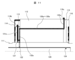
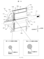
- FIG. 11 is a cross-sectional view of the upper half of the rotor 110 according to the third embodiment of the present invention, taken along the axial direction.
- first flow path and the second counter-load side flow path 132a were made to communicate with the shaft flow path 120 independently, but in the third embodiment, the first flow path The second flow path 132a (second flow path) on the opposite load side shares a connection portion with the shaft flow path 120.
- the outer peripheral surface of the rotor shaft 111 is provided with a second shaft passage hole 122 communicating with the shaft passage 120 and a fourth shaft passage hole 124 communicating with the shaft passage 120.
- the counter-load side second flow path 132a (second flow path) and the second shaft flow path hole 122 communicate with each other.
- Branch flow path 137 One end of a branch flow path 137 is connected to the second flow path 132a (second flow path) on the opposite load side, and the other end of the branch flow path 137 is connected to the first flow path 131a.
- the refrigerant discharged from the second shaft flow path hole 122 flows through the second flow path 132a (second flow path) on the opposite load side, is branched at a branch flow path 137, flows into the first flow path 131a, and enters the first flow path. It flows through path 131a.
- the subsequent flow of the refrigerant is the same as in Example 1, so the explanation will be omitted.
- the flow path structure can be simplified.
- connection of the third flow path and the fourth flow path to the shaft flow path is also the same, and the communication portion to the shaft flow path is shared.
- FIG. 12 is a cross-sectional perspective view taken along the axial direction of the rotor 110 according to the fourth embodiment of the present invention.
- Example 4 the cross-sectional areas of the anti-load side second flow path 132a and the load side second flow path 135a forming the second flow path are made different.
- the flow path cross-sectional area (upstream flow path cross-sectional area S u ) of the anti-load side second flow path 132a located on the upstream side of the second flow path is the flow path of the load-side second flow path 135a located on the downstream side.
- the cross-sectional area is greater than or equal to the cross-sectional area of the downstream flow path S d .
- the second flow path has been described in this embodiment, the first flow path, the third flow path, and the fourth flow path may be configured in the same manner.
- FIG. 13 is a cross-sectional perspective view taken along the axial direction of a rotor 110 according to a fifth embodiment of the present invention.
- the cross-sectional area of the first flow path 131a and the second flow path 132a on the opposite load side forming the second flow path are made different.
- the flow passage cross-sectional area S 1 of the first flow passage 131a is greater than or equal to the flow passage cross-sectional area (cross-sectional area S 2 of the second flow passage) of the anti-load side second flow passage 132a located on the upstream side of the second flow passage.
- the flow resistance of the first flow path is reduced, and the Since the flow rate ratio of the flow path can be increased, the cooling performance of the stator coil during low speed rotation can be improved.
- FIG. 14 is a cross-sectional perspective view taken along the axial direction of a rotor 110 according to a sixth embodiment of the present invention.
- the first shaft passage hole 121 and the second shaft passage hole 122 have different cross-sectional areas.
- the cross-sectional area S i1 of the first shaft passage hole 121 is less than or equal to the cross-sectional area S i2 of the second shaft passage hole 122 .
- the inlet pressure loss which is the main pressure loss during high-speed rotation, is reduced from the first flow path to the second flow path. Since the flow path can be made smaller, the flow rate ratio of the second flow path during high-speed rotation can be increased.
- notch third outlet
- 116c Fitting notch (second discharge port)
- 117... Permanent magnet 120... Shaft channel, 121... First shaft channel hole, 122... Second shaft channel hole, 123... Third shaft channel hole, 124 ... Fourth shaft passage hole, 130, 130a to 130h... Rotor core passage, 131... First groove, 131a... First passage, 132... Second groove, 132a...
- Counter-load side second passage (second flow 132s...damming part, 132e...radial outer end, 133...third groove, 133a...third flow path, 134...fourth groove, 134a...load side fourth flow path (fourth flow path) , 134s...damming part, 134e...radially outer end, 135...fifth groove 135a...load side second flow path (second flow path), 135e...radially inner end, 136...sixth groove, 136a ...Counter-load side fourth flow path (fourth flow path), 136e...Radially inner end, 137...Branch flow path, 140...Stator, 141...Starter coil, 150, 151, 152...Bearing, 154...Oil pan , 200... Reduction gear, 201... Drive gear, 202... Driven gear, 203... Driven gear shaft, 204, 205... Bearing
Landscapes
- Engineering & Computer Science (AREA)
- Power Engineering (AREA)
- Motor Or Generator Cooling System (AREA)
- Iron Core Of Rotating Electric Machines (AREA)
Priority Applications (3)
| Application Number | Priority Date | Filing Date | Title |
|---|---|---|---|
| DE112023000543.5T DE112023000543T5 (de) | 2022-06-15 | 2023-03-08 | Rotierende elektrische Maschine und damit ausgestattete Fahrzeugantriebsvorrichtung |
| US18/843,495 US20250202304A1 (en) | 2022-06-15 | 2023-03-08 | Rotating Electrical Machine and Vehicle Driving Device Equipped With Same |
| CN202380024073.1A CN118765478A (zh) | 2022-06-15 | 2023-03-08 | 旋转电机以及配备有该旋转电机的车辆驱动装置 |
Applications Claiming Priority (2)
| Application Number | Priority Date | Filing Date | Title |
|---|---|---|---|
| JP2022-096714 | 2022-06-15 | ||
| JP2022096714A JP2023183205A (ja) | 2022-06-15 | 2022-06-15 | 回転電機及びこれを備えた車両駆動装置 |
Publications (1)
| Publication Number | Publication Date |
|---|---|
| WO2023243161A1 true WO2023243161A1 (ja) | 2023-12-21 |
Family
ID=89192673
Family Applications (1)
| Application Number | Title | Priority Date | Filing Date |
|---|---|---|---|
| PCT/JP2023/008776 WO2023243161A1 (ja) | 2022-06-15 | 2023-03-08 | 回転電機及びこれを備えた車両駆動装置 |
Country Status (5)
Cited By (1)
| Publication number | Priority date | Publication date | Assignee | Title |
|---|---|---|---|---|
| JP7603860B1 (ja) * | 2024-03-05 | 2024-12-20 | MCF Electric Drive株式会社 | モータ冷却システム |
Citations (3)
| Publication number | Priority date | Publication date | Assignee | Title |
|---|---|---|---|---|
| JP2011142788A (ja) * | 2010-01-08 | 2011-07-21 | Toyota Motor Corp | 電動機の冷却構造 |
| JP2019187063A (ja) * | 2018-04-09 | 2019-10-24 | 日産自動車株式会社 | 回転電機 |
| CN111884428A (zh) * | 2020-06-28 | 2020-11-03 | 华为技术有限公司 | 电机、电机冷却系统及电动车 |
Family Cites Families (2)
| Publication number | Priority date | Publication date | Assignee | Title |
|---|---|---|---|---|
| JP2012223075A (ja) | 2011-04-14 | 2012-11-12 | Toyota Motor Corp | 回転電機の冷却構造 |
| JP2019068622A (ja) | 2017-09-29 | 2019-04-25 | アイシン・エィ・ダブリュ株式会社 | 回転電機 |
-
2022
- 2022-06-15 JP JP2022096714A patent/JP2023183205A/ja active Pending
-
2023
- 2023-03-08 DE DE112023000543.5T patent/DE112023000543T5/de active Pending
- 2023-03-08 US US18/843,495 patent/US20250202304A1/en active Pending
- 2023-03-08 WO PCT/JP2023/008776 patent/WO2023243161A1/ja active Application Filing
- 2023-03-08 CN CN202380024073.1A patent/CN118765478A/zh active Pending
Patent Citations (3)
| Publication number | Priority date | Publication date | Assignee | Title |
|---|---|---|---|---|
| JP2011142788A (ja) * | 2010-01-08 | 2011-07-21 | Toyota Motor Corp | 電動機の冷却構造 |
| JP2019187063A (ja) * | 2018-04-09 | 2019-10-24 | 日産自動車株式会社 | 回転電機 |
| CN111884428A (zh) * | 2020-06-28 | 2020-11-03 | 华为技术有限公司 | 电机、电机冷却系统及电动车 |
Cited By (1)
| Publication number | Priority date | Publication date | Assignee | Title |
|---|---|---|---|---|
| JP7603860B1 (ja) * | 2024-03-05 | 2024-12-20 | MCF Electric Drive株式会社 | モータ冷却システム |
Also Published As
| Publication number | Publication date |
|---|---|
| CN118765478A (zh) | 2024-10-11 |
| DE112023000543T5 (de) | 2024-10-31 |
| US20250202304A1 (en) | 2025-06-19 |
| JP2023183205A (ja) | 2023-12-27 |
Similar Documents
| Publication | Publication Date | Title |
|---|---|---|
| JP5734765B2 (ja) | 回転電機の冷却構造 | |
| CN102197572B (zh) | 旋转电机 | |
| WO2013136405A1 (ja) | 回転電機 | |
| CN104704723A (zh) | 液冷式电动机 | |
| JP2013115848A (ja) | 回転電機の冷却構造 | |
| KR20130029125A (ko) | 발전 전동기의 냉각 구조 및 발전 전동기 | |
| JP2020022232A (ja) | ステータコアの内部冷却構造 | |
| WO2023243161A1 (ja) | 回転電機及びこれを備えた車両駆動装置 | |
| CN115224837A (zh) | 转子组件以及用于马达端部绕组冷却和轴承润滑的方法 | |
| JP2012095381A (ja) | 車両用回転電機の冷却装置 | |
| JP2018014857A (ja) | 電動モータの冷却構造 | |
| JP2015204653A (ja) | 回転電機 | |
| CN215009955U (zh) | 电机冷却结构及电机 | |
| JP5710886B2 (ja) | 回転電機 | |
| JP3675363B2 (ja) | 回転電機 | |
| JP6332876B2 (ja) | 回転電機のロータ、および回転電機のロータの製造方法 | |
| JP7611990B1 (ja) | 回転電機 | |
| JP2019134573A (ja) | 回転電機のステータ | |
| CN220874289U (zh) | 转子组件、电机和车辆 | |
| JP7425023B2 (ja) | モータ | |
| KR102785909B1 (ko) | 축방향 영구자석 모터 오일 냉각 구조체 | |
| CN220964419U (zh) | 电机、转子组件和车辆 | |
| JP2020018116A (ja) | ロータ及び回転電気 | |
| CN218243259U (zh) | 电机油冷系统 | |
| CN115133716A (zh) | 电机冷却结构及电机 |
Legal Events
| Date | Code | Title | Description |
|---|---|---|---|
| 121 | Ep: the epo has been informed by wipo that ep was designated in this application |
Ref document number: 23823465 Country of ref document: EP Kind code of ref document: A1 |
|
| WWE | Wipo information: entry into national phase |
Ref document number: 202380024073.1 Country of ref document: CN |
|
| WWE | Wipo information: entry into national phase |
Ref document number: 112023000543 Country of ref document: DE |
|
| WWE | Wipo information: entry into national phase |
Ref document number: 18843495 Country of ref document: US |
|
| 122 | Ep: pct application non-entry in european phase |
Ref document number: 23823465 Country of ref document: EP Kind code of ref document: A1 |
|
| WWP | Wipo information: published in national office |
Ref document number: 18843495 Country of ref document: US |