WO2023243070A1 - 物品搬送装置及び物品搬送方法 - Google Patents
物品搬送装置及び物品搬送方法 Download PDFInfo
- Publication number
- WO2023243070A1 WO2023243070A1 PCT/JP2022/024256 JP2022024256W WO2023243070A1 WO 2023243070 A1 WO2023243070 A1 WO 2023243070A1 JP 2022024256 W JP2022024256 W JP 2022024256W WO 2023243070 A1 WO2023243070 A1 WO 2023243070A1
- Authority
- WO
- WIPO (PCT)
- Prior art keywords
- moving body
- road surface
- agv
- respect
- article
- Prior art date
- Legal status (The legal status is an assumption and is not a legal conclusion. Google has not performed a legal analysis and makes no representation as to the accuracy of the status listed.)
- Ceased
Links
Images




Classifications
-
- B—PERFORMING OPERATIONS; TRANSPORTING
- B61—RAILWAYS
- B61B—RAILWAY SYSTEMS; EQUIPMENT THEREFOR NOT OTHERWISE PROVIDED FOR
- B61B13/00—Other railway systems
-
- B—PERFORMING OPERATIONS; TRANSPORTING
- B62—LAND VEHICLES FOR TRAVELLING OTHERWISE THAN ON RAILS
- B62B—HAND-PROPELLED VEHICLES, e.g. HAND CARTS OR PERAMBULATORS; SLEDGES
- B62B3/00—Hand carts having more than one axis carrying transport wheels; Steering devices therefor; Equipment therefor
-
- B—PERFORMING OPERATIONS; TRANSPORTING
- B62—LAND VEHICLES FOR TRAVELLING OTHERWISE THAN ON RAILS
- B62D—MOTOR VEHICLES; TRAILERS
- B62D53/00—Tractor-trailer combinations; Road trains
Definitions
- the present disclosure relates to an article conveying device and an article conveying method.
- an AGV Automatic Guided Vehicle
- crawls into a certain space formed between the bottom surface of a truck and a floor surface to transport the truck see Patent Document 1.
- This AGV is equipped with a drive wheel and an air cylinder that is expandable and retractable in the vertical direction, and when the drive wheel rotates while the air cylinder applies an upward pushing force to the bottom of the trolley, goods such as luggage can be transported. move a truck loaded with
- the present disclosure aims to solve the above-mentioned problems, and to provide an article conveying device and an article conveying method that can improve workability when conveying articles than before.
- An article conveyance device includes a first moving body that moves in the road surface direction along the road surface by power of a drive source, and a first moving body that is movable in the road surface direction with respect to the first moving body. a second moving body that receives an external force from the first moving body and moves in the direction of the road surface together with the first moving body and conveys the loaded article;
- the vehicle is characterized by comprising an adjustment section that adjusts the movable range in the direction of the road surface.
- FIG. 1 is a perspective view showing a schematic configuration of an article conveying device according to Embodiment 1.
- FIG. 1 is a side view showing a schematic configuration of an article conveying device according to Embodiment 1.
- FIG. 1 is a bottom view showing a schematic configuration of an article conveying device according to Embodiment 1.
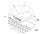
- FIG. 2 is an enlarged view A of FIG. 1 showing a connecting portion according to Embodiment 1.
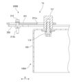
- FIG. FIG. 4 is a sectional view taken along line BB in FIG. 3 showing the connecting portion according to the first embodiment. 6 is a cross-sectional view showing a state of the connecting portion according to the first embodiment, which is different from that shown in FIG. 5.
- FIG. FIG. 7 is an enlarged view showing a connecting portion according to Embodiment 2.
- FIG. 7 is a cross-sectional view showing a connecting portion according to a second embodiment. 9 is a sectional view showing a state of the connecting portion according to the second embodiment, which is different from that shown in FIG. 8.
- FIG. FIG. 7 is an enlarged view showing a connecting portion according to Embodiment 3;
- FIG. 7 is a cross-sectional view showing a connecting portion according to Embodiment 3;
- 12 is a sectional view showing a state of the connecting portion according to Embodiment 3, which is different from that shown in FIG. 11.
- FIG. 1 is a perspective view showing a schematic configuration of an article conveying device 1 according to Embodiment 1
- FIG. 2 is a side view showing a schematic configuration of article conveying device 1 according to Embodiment 1
- FIG. 1 is a bottom view showing a schematic configuration of an article conveying device 1 according to Embodiment 1.
- the article conveyance device 1 includes an automatic guided vehicle (AGV) 100 that receives power and moves in a direction along a road surface, and a cart 200 on which an article W can be mounted.
- AGV automatic guided vehicle
- the article conveying device 1 conveys articles such as products being assembled and product parts along a preset route in a manufacturing line where products are assembled.
- an arbitrary direction along the road surface F is also referred to as a "road surface direction D" (see FIG. 2).
- the AGV 100 is capable of movement in the road surface direction D, including rotational movement around a virtual axis perpendicular to the road surface F, by the control unit 105 independently controlling the plurality of drive wheels 101. .
- the control unit 105 controls the plurality of drive wheels 101, so that the AGV 100 autonomously moves from a stopped position to a target position along a preset route on the road surface F. drive.
- the restriction unit 111 restricts the movable range of the trolley 200 with respect to the AGV 100. Details of the restriction unit 111 will be described later.
- the trolley 200 is electrically connected to a plurality of wheels 201, a trolley main body 202 supported by the plurality of wheels 201, a fixture 206 for fixing an article W to be transported, and a control section 105. , a positioning protrusion 207 for positioning the trolley 200 with another device (not shown), and a restricted portion 211 (see FIG. 4). Note that in the first embodiment, the truck 200 constitutes a second moving body.
- the weight of the article W mounted on the truck 200 is transmitted to the plurality of wheels 201 via the truck body 202. This suppresses the weight of the article W from being transmitted to the drive wheels 101 of the AGV 100, and reduces the burden on the drive wheels 101 and the drive source 103.
- the bogie 200 is connected to the AGV 100, and when the AGV 100 moves in the road direction D, it receives an external force such as a pushing force or a tensile force in the road direction D from the AGV 100, and moves in the road direction D together with the AGV 100.
- the truck 200 moves in the road direction D following the AGV 100.
- the truck 200 moves in the road direction D by the power of the drive source 103 received via the AGV main body 102.
- the trolley 200 is connected to the AGV 100 so as to be movable in the road surface direction D relative to the AGV 100.
- the AGV 100 and the truck 200 are connected at the connection portion T1 so that they can move relative to each other in the road surface direction D.
- the AGV 100 and the trolley 200 are connected by two connecting portions T1 arranged at different positions in a plan view (see FIG. 3).
- FIG. 4 is an enlarged view B of FIG. 1 showing a connecting portion T1 according to the first embodiment in which the AGV 100 and the truck 200 are connected so that they can move relative to each other
- FIG. 5 is an enlarged view B according to the first embodiment.
- FIG. 4 is a cross-sectional view taken along line BB in FIG. 3 showing the connecting portion T1. Note that since the two connecting portions T1 have the same configuration, only one of the connecting portions T1 will be described, and a description of the other connecting portion T1 will be omitted.
- the AGV 100 has a restriction part 111 that limits the range in which the truck 200 can move in the road surface direction D with respect to the AGV 100.
- the restricting portion 111 is formed to protrude upward from the AGV main body 102, and is held on the AGV main body 102 by a fastener 112.
- the truck 200 also includes a restricted portion 211 whose movement in the road surface direction D with respect to the restricted portion 111 is restricted.
- the restricted portion 211 is held on the truck body 202 by a fastener 212.
- the restricted portion 211 has a hole 211a formed along the vertical direction into which the restricting portion 111 is inserted.
- the restricted portion 211 is formed into a plate shape along the road surface direction D, and has a hole portion 211a that is a through hole.
- the hole 211a of the restricted portion 211 is formed larger than the restricting portion 111.
- the hole 211a of the restricted portion 211 is formed to have a larger dimension in the road surface direction D than the restricted portion 111. Therefore, for example, the distance (L1-L2) corresponding to the difference between the dimension L1 of the hole 211a and the dimension L2 of the restriction part 111 in the road surface direction D is the distance that the bogie 200 can move in the road surface direction D with respect to the AGV 100. It becomes the distance.
- the trolley 200 can move relative to the AGV 100 within a range where the inner surface of the hole 211a does not come into contact with the restriction part 111.
- the restricted portion 211 is in contact with the restricting portion 111 .
- the article conveyance device 1 moves only the trolley 200 in the road direction D with the AGV 100 stopped, even if the stop position of the AGV 100 deviates from the target position. It becomes possible to move the article W and position it with another device, for example, an automatic machine that works on the article W unmanned.
- the work performed by the automatic machine includes attaching other parts to the article W, tightening screws to the article W, inspecting the article W, and the like.
- the screw cannot be tightened depending on the amount of misalignment, so it is necessary to improve work efficiency. may be difficult.
- the article conveyance device 1 is capable of adjusting the range in which the trolley 200 can move in the road surface direction D with respect to the AGV 100, and the range can be set in advance to an appropriate range. can do.
- the fastener 212 for holding the restricted portion 211 on the trolley body 202 has a threaded portion 212a extending in the vertical direction. It is screwed into a screw hole (not shown) in the The restricted portion 211 rotatably holds the fastener 212 and is configured such that its relative position with the fastener 212 in the vertical direction remains constant regardless of the rotational position of the fastener 212. Therefore, the restricted portion 211 moves in the vertical direction with respect to the truck body 202 as the fastener 212 rotates with respect to the truck body 202.
- FIG. 6 is a sectional view showing a state of the connecting portion T1 according to the first embodiment, which is different from that in FIG. 5, and is a BB sectional view in FIG. 3. Specifically, FIG. 6 is a BB sectional view showing a state in which the restricted portion 211 has moved upward with respect to the truck body 202 compared to FIG. 5 in the connecting portion T1 according to the first embodiment.
- the restricting portion 111 has an inclined surface 111a that is inclined with respect to the vertical direction.
- the restricting portion 111 has an inclined surface 111a formed so that the diameter gradually decreases toward the tip.
- the article conveyance device 1 according to the first embodiment sets the distance that the trolley 200 can move in the road surface direction D with respect to the AGV 100 to the first distance (L1-L2) shown in FIG. (L1-L2) and a second distance (L1-L3) shown in FIG. 6, which is different from (L1-L2).
- the article conveyance device 1 according to the first embodiment can adjust in advance the movable range of the trolley 200 with respect to the AGV 100 so that the range corresponds to the accuracy of the stop position of the AGV 100. Therefore, it is possible to improve workability when transporting the article W.
- the worker S in the first step loads the article W onto the top plate 203 with the article conveyance device 1 located at a preset position, and uses the fixture 206 to place the article W onto the top plate 203. Fix it.
- the worker S operates the operation unit 205 to move the AGV 100 toward the target position of the second process, which is the next process.
- the worker S who receives the article W in the second step determines whether the article W conveyed by the article conveyance device 1 has stopped at a preset target position. If it has not stopped at the preset target position, the worker S of the process moves only the trolley 200 so that the article W is located at the target position while the AGV 100 is stopped. At this time, if the movable range of the cart 200 with respect to the AGV 100 is too small or too large, the worker S of the process may, for example, move the restricted part 211 with respect to the cart main body 202 and adjusts the movable range for the AGV 100.
- another device may receive the article W instead of the worker S.
- an automatic machine that performs work on the article W in the second process receives the article W
- the positioning machine that positions the cart 200
- the cart 200 is positioned by activating a device (not shown) and inserting the positioning protrusion 207 into a positioning hole formed in the positioning device.
- the positioning protrusion 207 is inserted into the positioning hole while the inner surface of the positioning hole contacts the guide portion of the positioning protrusion 207, so that only the cart 200 moves while the AGV 100 is stopped.
- the article conveyance device 1 includes the AGV 100 that moves in the road surface direction D along the road surface F by the power of the drive source 103, and the AGV 100 that is movable in the road surface direction D with respect to the AGV 100.
- the trolley 200 receives an external force from the AGV 100 when moving to the direction D, moves in the road surface direction D together with the AGV 100, and transports the loaded article W.
- the article conveying device 1 includes a connecting portion T1 that adjusts the range in which the trolley 200 can move in the road surface direction D with respect to the AGV 100. This makes it possible to set the range in which the trolley 200 can move in the road direction D relative to the AGV 100 to an appropriate range in advance, for example, depending on the accuracy of the stopping position of the AGV 100. It becomes possible to improve workability during transportation.
- the AGV 100 and the trolley 200 each have three omni-wheels in the article conveyance device 1, but the present invention is not limited to this.
- the AGV and the truck only need to be movable in the road surface direction D, and may each have a plurality of omnidirectional movable wheels other than omni-wheels, or may have other wheels.
- examples of omnidirectional wheels include Mecanum wheels (registered trademark), ball casters, and the like.
- it is desirable that the AGV and the trolley each have three wheels, etc., but they may each have four or more wheels, and if they can stand on their own, the number of wheels for each can be reduced to two. It may be one or more.
- the AGV is not limited to those having only omnidirectional wheels as driving wheels, but also those having omnidirectional moving wheels as driving wheels and swing casters as driven wheels.
- the omnidirectional wheels instead of the omnidirectional wheels, it may include swing casters and a steering device for steering the swing casters.
- the trolley is not limited to one having omnidirectionally movable wheels, and may have swing casters instead of the omnidirectionally movable wheels.
- the article conveyance device 1 is configured to be movable in any direction along the road surface F, but is not limited to this.
- the AGV may be configured to move only in one direction along the road surface F, and the trolley may be configured to be movable only in the one direction relative to the AGV.
- the wheels of the AGV do not need to be omnidirectional wheels or steerable swing casters, and the orientation is fixed. It may also be a wheel that is
- the AGV 100 is configured to autonomously travel along a preset route on the road surface F, but the present invention is not limited thereto.
- the AGV only needs to be configured to move in the road direction D by the power of the drive source.
- the AGV receives a signal wirelessly or by wire from a controller provided outside the article conveyance device.
- the vehicle may be configured to move in the road surface direction D along a route set based on the signal.
- the AGVs may be able to move relative to each other while being mounted on a trolley, or the trolleys may be movable relative to each other while being mounted on the AGV.
- the truck since the weight of the articles mounted on the truck is transmitted to the drive wheels and drive source of the AGV, it is desirable that the truck be in contact with the road surface without going through the AGV.
- the article conveyance apparatus 1 is configured such that the AGV 100 and the trolley 200 are connected by two connecting portions T1 disposed at mutually different positions in a plan view.
- the AGV and the trolley only need to be configured to be relatively movable within a predetermined range in the road surface direction D, and for example, they may be connected by three or more connecting parts disposed at mutually different positions in a plan view. However, they may be connected by one connecting part.
- the AGV and the truck may be connected by one connection part.
- the AGV and the bogie do not need to be connected to each other; for example, one of the AGV and the bogie may surround the outer shape of the other so that the AGV and the bogie can move relative to each other within a predetermined range in the road surface direction D. may be formed.
- the trolley 200 receives an external force from the AGV 100 when the restricted portion 211 contacts the restricted portion 111, and is able to move in the road surface direction D together with the AGV 100, but the present invention is not limited thereto.
- the truck may be configured to be movable in the road direction D upon receiving an external force from the AGV.
- the truck may be configured to be movable in the road direction D upon receiving an external force from the AGV via another configuration not shown.
- it may be configured to be movable in the road surface direction D by receiving an external force from the AGV without coming into contact with the AGV using magnetic force, air pressure, or the like.
- the article conveyance device 1 allows the cart 200 to move relative to the AGV 100 by rotating the fastener 212 and changing the vertical position of the restricted portion 211 with respect to the cart main body 202.
- the range is configured to be adjustable, the range is not limited thereto.
- the restricting portion 111 of the connecting portion T1 has an inclined surface 111a with which the inner surface of the hole portion 211a comes into contact, and the restricting portion 111 of the connecting portion T1 has an inclined surface 111a that is in contact with the inner surface of the hole portion 211a.
- the configuration allows stepless adjustment of the movable range of the AGV 200 relative to the AGV 100, the present invention is not limited thereto.
- the article conveyance device 1 has the hole 211a of the restricted portion 211 formed larger than the restriction portion 111 in plan view, and the inner surface of the hole 211a is Although it is configured to be able to move within a range that does not come into contact with the restricting portion 111, the present invention is not limited thereto.
- the cart does not need to be movable in the road direction D with respect to the AGV in any state;
- the movable range of the bogie relative to the AGV may be adjustable, and if the bogie does not need to be moved in the road surface direction D relative to the AGV, it may include a fixing portion that fixes the bogie and the AGV to each other. You can leave it there.
- FIG. 9 is a cross-sectional view showing a state of the connecting portion T2 according to the second embodiment that is different from that shown in FIG. 8.
- FIG. 3 is a sectional view showing a state in which the restricted portion 221 has moved upward with respect to the truck body 202.
- the restricted portion 221 has an inclined surface 221a that is inclined with respect to the vertical direction and forms a hole P.
- the restricted portion 221 has an inclined surface 221a formed on the inner surface of the hole P so that the diameter gradually decreases upward. Therefore, the article conveyance device according to the second embodiment rotates the fastener 212 to change the vertical position of the restricted portion 221 with respect to the trolley body 202, so that the restricted portion 121 can contact the inclined surface.
- Embodiment 3 an article conveying apparatus according to a third embodiment will be described with reference to FIGS. 10 to 12.
- the article conveyance device 1 according to the third embodiment differs from the article conveyance device 1 according to the first embodiment in the configuration of the connecting portion where the AGV and the trolley are connected, but the other configurations are the same.
- the same configurations as those in Embodiment 1 are designated by the same reference numerals and the description thereof will be omitted.
- the hole 231a is formed to be a long hole that is longer in one direction of the road surface direction D than in the other direction.
- the hole portion 231a is formed to be a long hole whose length in the left-right direction shown in FIG. longer than the length of
- the restricted portion 231 is configured to be movable in the one direction relative to the fastener 212 and the truck body 202 by loosening the hold by the fastener 212.
- FIG. 12 is a cross-sectional view showing a state of the connecting portion T3 according to the third embodiment that is different from that shown in FIG. 11.
- FIG. 2 is a sectional view showing a state in which the restricted portion 231 has moved to the right (outward), which is one direction of the road surface direction D, with respect to the truck body 202.
- FIG. For example, in the plurality of connecting portions T3 included in the article conveying device, by moving the restricted portion 231 outward with respect to the cart body 202 from the state shown in FIG. 11 to the state shown in FIG. The range in which the AGV 200A can move relative to the AGV 100A can be reduced.
- the connection part T3 constitutes the adjustment part which adjusts the range in which the 2nd moving body can move in the road surface direction with respect to the 1st moving body.
- the article conveyance device according to the present disclosure can be used, for example, to convey products on a manufacturing line without using a conveyor.
- One of the limiting portion and the limited portion has an inclined surface that is inclined with respect to the vertical direction
- the other of the restricting part and the restricted part has an abutting part that can abut with the inclined surface
- the adjustment section adjusts at least one of the vertical position of the limiting section with respect to the first moving body and the vertical position of the restricted section with respect to the second moving body, so that the abutment section is brought into contact with the first moving body.
- the article conveyance according to appendix 3 characterized in that the range in which the second moving body can move in the direction of the road surface relative to the first moving body is adjusted by changing the position on the inclined surface that can be contacted. Device.
- the first moving body includes a plurality of omnidirectional moving wheels and a moving body main body supported by the plurality of omnidirectional moving wheels.
- Goods conveyance device. (Appendix 8) A method for transporting articles carried out by an apparatus including a first moving body and a second moving body movable in a road surface direction along a road surface with respect to the first moving body, a step in which the first moving body moves in the direction of the road surface by power of a drive source; When the first moving body moves in the direction of the road surface, the second moving body receives an external force from the first moving body and moves together with the first moving body in the direction of the road surface, and transports the loaded article.
- the step of An article conveyance method comprising: moving the second moving body in the direction of the road surface relative to the first moving body while the first moving body is stopped.
Landscapes
- Engineering & Computer Science (AREA)
- Transportation (AREA)
- Mechanical Engineering (AREA)
- Chemical & Material Sciences (AREA)
- Combustion & Propulsion (AREA)
- Handcart (AREA)
- Platform Screen Doors And Railroad Systems (AREA)
Priority Applications (3)
| Application Number | Priority Date | Filing Date | Title |
|---|---|---|---|
| CN202280097159.2A CN119365380A (zh) | 2022-06-17 | 2022-06-17 | 物品搬运装置及物品搬运方法 |
| PCT/JP2022/024256 WO2023243070A1 (ja) | 2022-06-17 | 2022-06-17 | 物品搬送装置及び物品搬送方法 |
| JP2024528052A JPWO2023243070A1 (https=) | 2022-06-17 | 2022-06-17 |
Applications Claiming Priority (1)
| Application Number | Priority Date | Filing Date | Title |
|---|---|---|---|
| PCT/JP2022/024256 WO2023243070A1 (ja) | 2022-06-17 | 2022-06-17 | 物品搬送装置及び物品搬送方法 |
Publications (1)
| Publication Number | Publication Date |
|---|---|
| WO2023243070A1 true WO2023243070A1 (ja) | 2023-12-21 |
Family
ID=89192631
Family Applications (1)
| Application Number | Title | Priority Date | Filing Date |
|---|---|---|---|
| PCT/JP2022/024256 Ceased WO2023243070A1 (ja) | 2022-06-17 | 2022-06-17 | 物品搬送装置及び物品搬送方法 |
Country Status (3)
| Country | Link |
|---|---|
| JP (1) | JPWO2023243070A1 (https=) |
| CN (1) | CN119365380A (https=) |
| WO (1) | WO2023243070A1 (https=) |
Citations (3)
| Publication number | Priority date | Publication date | Assignee | Title |
|---|---|---|---|---|
| JPH0732168Y2 (ja) * | 1987-01-19 | 1995-07-26 | 株式会社ダイフク | 台車連結装置 |
| JPH08301123A (ja) * | 1995-05-02 | 1996-11-19 | Tokyo Ubaguruma Kk | 手押し4輪台車の車輪とストッパ |
| JP2021094966A (ja) * | 2019-12-16 | 2021-06-24 | スキューズ株式会社 | 全方位台車搬送機構 |
Family Cites Families (2)
| Publication number | Priority date | Publication date | Assignee | Title |
|---|---|---|---|---|
| JP2956184B2 (ja) * | 1990-09-28 | 1999-10-04 | スズキ株式会社 | 無人搬送車用牽引装置 |
| JPH1024838A (ja) * | 1996-07-09 | 1998-01-27 | Unisia Jecs Corp | 無人搬送車用連結切り離しユニット |
-
2022
- 2022-06-17 CN CN202280097159.2A patent/CN119365380A/zh active Pending
- 2022-06-17 JP JP2024528052A patent/JPWO2023243070A1/ja active Pending
- 2022-06-17 WO PCT/JP2022/024256 patent/WO2023243070A1/ja not_active Ceased
Patent Citations (3)
| Publication number | Priority date | Publication date | Assignee | Title |
|---|---|---|---|---|
| JPH0732168Y2 (ja) * | 1987-01-19 | 1995-07-26 | 株式会社ダイフク | 台車連結装置 |
| JPH08301123A (ja) * | 1995-05-02 | 1996-11-19 | Tokyo Ubaguruma Kk | 手押し4輪台車の車輪とストッパ |
| JP2021094966A (ja) * | 2019-12-16 | 2021-06-24 | スキューズ株式会社 | 全方位台車搬送機構 |
Also Published As
| Publication number | Publication date |
|---|---|
| JPWO2023243070A1 (https=) | 2023-12-21 |
| CN119365380A (zh) | 2025-01-24 |
Similar Documents
| Publication | Publication Date | Title |
|---|---|---|
| EP3660619B1 (en) | Two wheel automatic guided vehicles used in combination | |
| CN110073589B (zh) | 用于受控地相对定子输送运输体的具有定子的输送装置 | |
| TWI772404B (zh) | 物品搬送設備 | |
| KR102601104B1 (ko) | 물품 반송 설비 | |
| US20110245964A1 (en) | Self Aligning Automated Material Handling System | |
| CN113905972B (zh) | 紧凑型自主全向驱动单元 | |
| US11787649B2 (en) | System and method for determining real-time orientation on carts in an independent cart system | |
| KR102460494B1 (ko) | 자율주행이 가능한 무인 운반차 | |
| KR20200138486A (ko) | 하역장치 | |
| US11701920B2 (en) | Driving wheel, carriage, and apparatus | |
| EP2821324A1 (en) | Method for transporting an object with an automatically controllable vehicle in an object processing system, vehicle and object processing system. | |
| JP5485643B2 (ja) | 搬送装置の制御装置 | |
| WO2023243070A1 (ja) | 物品搬送装置及び物品搬送方法 | |
| CN107272693A (zh) | 基于全向车与装配工位自动对接系统及方法 | |
| CA3133406C (en) | Method and device for controlling the movement of a mobile chassis assembly, in particular of a mobile conveyor bridge system provided with crawler chassis, via multiple individually speed-controllable drive units | |
| US10730346B2 (en) | Caster apparatus and transferring apparatus including the same | |
| US4781514A (en) | Material handling vehicle load retention apparatus | |
| US20180002151A1 (en) | End effector for a transport device for the movement of parent rolls of convolutely wound web materials | |
| US12272582B2 (en) | Overhead conveyance system | |
| JP7405053B2 (ja) | 無人搬送車 | |
| KR102839906B1 (ko) | 물품 반송차 | |
| KR102170507B1 (ko) | 부품 이송 시스템 | |
| TR2024018140T2 (tr) | Eşya taşima terti̇bati ve eşya taşima yöntemi̇. | |
| JP7677513B2 (ja) | 搬送設備 | |
| JP7476751B2 (ja) | 無人搬送車 |
Legal Events
| Date | Code | Title | Description |
|---|---|---|---|
| 121 | Ep: the epo has been informed by wipo that ep was designated in this application |
Ref document number: 22946886 Country of ref document: EP Kind code of ref document: A1 |
|
| ENP | Entry into the national phase |
Ref document number: 2024528052 Country of ref document: JP Kind code of ref document: A |
|
| WWE | Wipo information: entry into national phase |
Ref document number: 2024/018140 Country of ref document: TR |
|
| WWE | Wipo information: entry into national phase |
Ref document number: 2401008292 Country of ref document: TH Ref document number: 202280097159.2 Country of ref document: CN |
|
| NENP | Non-entry into the national phase |
Ref country code: DE |
|
| WWP | Wipo information: published in national office |
Ref document number: 202280097159.2 Country of ref document: CN |
|
| WWP | Wipo information: published in national office |
Ref document number: 2024/018140 Country of ref document: TR |
|
| 122 | Ep: pct application non-entry in european phase |
Ref document number: 22946886 Country of ref document: EP Kind code of ref document: A1 |