WO2023238501A1 - データ通信システム、データ通信方法、中継装置、中継方法、及びプログラム - Google Patents
データ通信システム、データ通信方法、中継装置、中継方法、及びプログラム Download PDFInfo
- Publication number
- WO2023238501A1 WO2023238501A1 PCT/JP2023/014927 JP2023014927W WO2023238501A1 WO 2023238501 A1 WO2023238501 A1 WO 2023238501A1 JP 2023014927 W JP2023014927 W JP 2023014927W WO 2023238501 A1 WO2023238501 A1 WO 2023238501A1
- Authority
- WO
- WIPO (PCT)
- Prior art keywords
- communication
- data
- communication frame
- frame
- cycle
- Prior art date
- Legal status (The legal status is an assumption and is not a legal conclusion. Google has not performed a legal analysis and makes no representation as to the accuracy of the status listed.)
- Ceased
Links
Images











Classifications
-
- H—ELECTRICITY
- H04—ELECTRIC COMMUNICATION TECHNIQUE
- H04L—TRANSMISSION OF DIGITAL INFORMATION, e.g. TELEGRAPHIC COMMUNICATION
- H04L12/00—Data switching networks
- H04L12/28—Data switching networks characterised by path configuration, e.g. LAN [Local Area Networks] or WAN [Wide Area Networks]
- H04L12/40—Bus networks
- H04L12/4013—Management of data rate on the bus
-
- H—ELECTRICITY
- H04—ELECTRIC COMMUNICATION TECHNIQUE
- H04L—TRANSMISSION OF DIGITAL INFORMATION, e.g. TELEGRAPHIC COMMUNICATION
- H04L12/00—Data switching networks
- H04L12/28—Data switching networks characterised by path configuration, e.g. LAN [Local Area Networks] or WAN [Wide Area Networks]
-
- H—ELECTRICITY
- H04—ELECTRIC COMMUNICATION TECHNIQUE
- H04L—TRANSMISSION OF DIGITAL INFORMATION, e.g. TELEGRAPHIC COMMUNICATION
- H04L12/00—Data switching networks
- H04L12/28—Data switching networks characterised by path configuration, e.g. LAN [Local Area Networks] or WAN [Wide Area Networks]
- H04L12/42—Loop networks
- H04L12/423—Loop networks with centralised control, e.g. polling
-
- H—ELECTRICITY
- H04—ELECTRIC COMMUNICATION TECHNIQUE
- H04L—TRANSMISSION OF DIGITAL INFORMATION, e.g. TELEGRAPHIC COMMUNICATION
- H04L12/00—Data switching networks
- H04L12/28—Data switching networks characterised by path configuration, e.g. LAN [Local Area Networks] or WAN [Wide Area Networks]
- H04L12/42—Loop networks
- H04L12/427—Loop networks with decentralised control
- H04L12/43—Loop networks with decentralised control with synchronous transmission, e.g. time division multiplex [TDM], slotted rings
Definitions
- the present disclosure relates to a data communication system, a data communication method, a relay device, a relay method, and a program that extend the data communication distance between a master and a slave in EtherCAT (registered trademark) communication.
- EtherCAT registered trademark
- FIG. 19 is a block diagram illustrating data transmission and reception in EtherCAT communication.
- the EtherCAT communication frame is transmitted from the master device M-1 that controls the entire system, passes through all the slave devices S-1 to SN in the order in which they were connected, and is sent to the terminal terminal. When it arrives at the slave device SN, it reverses its outward route and returns to the master device M-1 again.
- EtherCAT can perform time-synchronized communication by measuring the time difference from transmission to return of a communication frame and correcting it from the master clock. That is, time synchronization is performed by the master device writing the time in a communication frame, and each slave device reading the time and calculating the time delay between its own node and the master device.
- processing data in each slave device is stored together (data packing).
- the slave device uses a communication method that transmits and receives processing data (on-the-fly reading and writing) when the communication frame passes through its own node.By transmitting processing data in short cycles, it achieves real-time performance (low delay). ) has been realized.
- EtherCAT communication passes through all slave devices in order from the master device in one direction, reads and writes processing data during the first pass, and does not perform any processing during the second pass (when returning). Therefore, communication between slave devices had to be realized by repeating two cycles of transmitting and receiving communication frames.
- communication between slave devices is also referred to as feedback communication or FB communication.
- Communication between slave devices is typified by feedback (FB) control communication.
- FB control refers to controlling the output so that it reaches an appropriate target value or reference value by sending an output signal back to the input side.
- master device M-1 transmits communication frames to slave device S-1 in two cycles, a first cycle and a second cycle.
- Non-Patent Document 1 describes an overview of EtherCAT technology.
- FIG. 20 is a block diagram illustrating FB (feedback) control communication in EtherCAT.
- EtherCAT communication periodic communication between master and slave is performed in one direction, so communication between slave devices, typified by FB (feedback) control communication, is performed in the first cycle and in the first cycle. This was realized by transmitting and receiving data in two cycles. Therefore, FB communication delay depends on the communication distance between master and slave, and it is not possible to mix short-cycle FB communication with short communication time and long-cycle FB communication with long communication time on the EtherCAT system.
- Ta data communication performed in short cycles is also referred to as short cycle communication
- data communication performed in long cycles is also referred to as long cycle communication.
- master device M-1 performs short-cycle communication with slave devices S-1 and S-2.
- master device M-1 In the first cycle, when slave device S-2 writes data to perform FB control to S-1, master device M-1 reads the data in the returned communication frame, and in the second cycle A communication frame in which the data is written is transmitted to device S-1.
- slave device S-3 moves to a remote location where long-cycle communication is required
- master device M-1 performs short-cycle communication with slave device S-3. become unable to do so. For this reason, when installing a processing part that requires low latency in addition to the remote control target, such as in edge computing, near a master device that requires short-cycle responses, a separate node can reduce the communication distance. There was no choice but to additionally construct a new master/slave system to meet the requirements, and economical support for using the same node was an issue.
- FIG. 21 is a block diagram illustrating an example of a known technique that achieves extended data communication through IP communication between master devices.
- a master-slave system that performs short-cycle communication, consisting of a master device M-1, slave devices S-1 and S-2 that require short-cycle responses, and a master device M-1.
- a master-slave system that performs long-cycle communication and is configured by a slave device S-3 and a slave device S-3 to be remotely controlled coexists.
- master device M-1 manages slave devices S-1 and S-2 that can handle short-cycle communication
- master device M-2 manages slave device S-3 that can't handle short-cycle communications.
- the master devices M-1 and M-2 perform IP communication. A specific system operation will be described with reference to FIG. 21.
- the master device M-1 transmits a communication frame containing the data written by the slave device S-3, so that the FB control from the slave device S-3 to S-1 is indirectly performed. It is carried out according to However, even with the master-slave system shown in FIG. 22, there is a problem in that FB control from the slave device S-3 can only be performed once every several short cycles. Furthermore, it was necessary to additionally construct a new master/slave system, which posed an economic challenge.
- FIG. 23 is a block diagram showing a configuration example of a slave device.
- the slave device includes an input/output unit that is responsible for inputting and outputting data, a slave controller that reads and writes data addressed to its own node, and a device controller that communicates with devices. .
- the data communication system is a data communication system that extends the communication distance in EtherCAT communication, in which a first communication frame in which data is stored is transmitted in a first communication cycle.
- a master device transmits data to a slave device or relay device, reads and writes data to the first communication frame, and sends the first communication frame to the master device, a lower slave device, or the relay device.
- the relay device is a relay device that relays between communications with different communication cycles in EtherCAT communication, and transmits a second communication frame that is a copy of a received first communication frame.
- a copying unit that reads and writes the data stored in the second communication frame, and reads and writes the data stored in the second communication frame, and the absolute time of the relay device on the first communication cycle and the absolute time of the remote slave device on the second communication cycle.
- the data written in the second communication frame received from the remote slave device in the second communication cycle is transferred to the first communication frame, and the first communication is performed.
- a first control unit that periodically transmits data to the master device or the slave device.
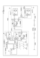
- FIG. 1 is a block diagram showing a configuration example of a data communication system according to a first embodiment
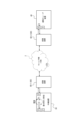
- FIG. 2 is a block diagram illustrating a configuration example of a relay device according to the first embodiment
- 3 is a flowchart illustrating an example of a data communication method executed by the data communication system according to the first embodiment.
- 3 is a flowchart illustrating an example of a relay method executed by the relay device according to the first embodiment.
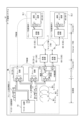
- FIG. 2 is a block diagram showing a configuration example of a data communication system according to a second embodiment.
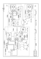
- FIG. 2 is a block diagram showing a configuration example of a relay device according to a second embodiment.
- FIG. 7 is a diagram showing a database managed by a slave management unit according to the second embodiment.
- FIG. 2 is a block diagram illustrating an example of a known technique that achieves a longer communication distance through bridge communication that connects slave devices.
- FIG. 2 is a block diagram showing a configuration example of a slave device.
- FIG. 2 is a block diagram showing a configuration example of a bridge device.
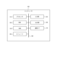
- FIG. 1 is a block diagram showing a configuration example of a data communication system 1 according to the first embodiment.
- the data communication system 1 includes a master device 10, slave devices 20 (20-1 to 20-n), a relay device 30, and a remote slave device 40.
- the slave devices 20 (20-1 to 20-n) can be composed of one or more slave devices.
- Remote slave device 40 and slave device 20 have the same functions.
- one or more remote slave devices 40 can be installed, they are also referred to as remote slave devices 40-1 to 40-m.
- the data communication system 1 extends the communication distance between a master device and a slave device in EtherCAT communication.
- a relay device (also referred to as a proxy slave) 30 is connected to the front or rear stage of the slave devices 20 (20-1 to 20-n).
- the relay device 30 (i) creates a second communication frame that is a copy of the first communication frame received from the master device 10 or the slave device 20, and (ii) performs data reading and processing on the second communication frame. (iii) synchronize the absolute time of the relay device 30 on the first communication cycle with the absolute time of the remote slave device 40 on the second communication cycle, and (iv) synchronize the absolute time of the relay device 30 on the first communication cycle. transmits the second communication frame to the remote slave device 40, and (v) places the data written in the second communication frame received from the remote slave device 40 in the second communication cycle on the first communication frame.
- the second communication cycle refers to a long cycle, that is, the second communication frame transmitted from the output unit (IF) of the slave device on the remote slave device 40 side of the relay device 30 is transmitted to the remote slave device 40. This refers to the time it takes for the signal to be received at the output section (IF) of the slave device on the remote slave device 40 side of the relay device 30 via the relay device 30.
- the second communication frame refers to a communication frame created by the relay device 30 by duplicating the first communication frame.
- the relay device 30 corrects the absolute time of the remote slave device 40 on the second communication cycle, which is a longer cycle than the first communication cycle, to the absolute time of the relay device 30 on the first communication cycle, and then corrects the absolute time of the remote slave device 40 on the second communication cycle, which is longer than the first communication cycle, to the absolute time of the relay device 30 on the first communication cycle.
- the absolute time of the relay device 30 on the first communication cycle and the absolute time of the remote slave device 40 on the second communication cycle are aligned.
- the relay device 30 can relay communication between the first communication cycle and the second communication cycle.
- the relay device 30 transmits a second communication frame containing data to a remote slave device 40 installed within a communication range in a second communication cycle.
- the remote slave device 40 (40-1 to 40-m) reads and writes data to the second communication frame received from the relay device 30, and completes reading and writing the data to the relay device 30. A second communication frame is sent back.
- the remote slave device 40 (40-1 to 40-m) is installed in a remote location where it cannot communicate in the first communication cycle, and communicates with the relay device 30 in a cycle longer than the first communication cycle. Communication is performed in a certain second communication cycle.
- the remote slave device 40 (40-1 to 40-m) and each slave device of the plurality of slave devices 20 (20-1 to 20-n) have the same function.
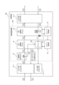
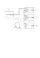
- FIG. 2 is a block diagram showing a configuration example of the relay device 30 according to the first embodiment.
- the relay device 30 includes an input/output section 31 (31-1 to 31-3), a duplication section 32, a first control section 33, and a second control section .
- the relay device 30 relays communication between different communication cycles in EtherCAT communication.
- the relay device 30 is significantly different from the conventional slave device shown in FIG. 22 or the conventional bridge device block diagram shown in FIG. 23 in that it includes a repeater 32.
- the relay device 30 will be described as being connected to the downstream of the plurality of slave devices 20, but the relay device 30 is connected to the master device 10 and the plurality of slave devices 20 connected to the master device 10.
- the slave device 20 may be placed within a range where short-cycle communication is possible between the slave devices 20 and the slave device 20, and may be placed before or after the slave device 20.
- a control calculation circuit (controller) 50 is configured by the duplication section 32, the first control section 33, and the second control section 34.
- the control calculation circuit 50 may be configured by dedicated hardware such as an ASIC (Application Specific Integrated Circuit) or an FPGA (Field-Programmable Gate Array), or may be configured by a processor, or may be configured by including both. may be done.
- the input/output unit 31 (31-1 to 31-3) is in charge of inputting/outputting a first communication frame or a second communication frame with the master device 10, slave device 20, or remote slave device 40.
- the input/output unit 31 (31-1 to 31-3) is composed of a physical layer transceiver device (EtherPHY) for transmitting and receiving Internet frames (communication frames).
- EtherPHY physical layer transceiver device
- the duplication unit 32 creates a second communication frame b by duplicating the received first communication frame a.
- the duplication unit 32 outputs the first communication frame a and the duplicated second communication frame b to the first control unit.
- the first control unit 33 (i) reads and writes data stored in the second communication frame b, and (ii) sets the absolute time of the relay device 30 on the first communication cycle and the second communication cycle. Synchronization is performed with the absolute time of the remote slave device 40 above, and (iii) the second communication frame b is output to the second control unit 34 at the subsequent stage. Furthermore, (iv) the first control unit 33 receives the data dr written in the second communication frame b that the second control unit 34 received from the remote slave device 40 in the second communication cycle, and stores it in the memory 33A. , (v) Replace the data dr in the first communication frame a received from the duplication unit 32. (vi) Then, the first control unit 33 sends the first communication frame a in which the data dr is written to the input/output unit 31-2, and sends it to the master device 10 or slave device 20 in the first communication cycle. Send.
- the second control unit 34 communicates with the subsequent remote slave device 40 via the input/output unit 31-2 in the second communication cycle.
- the second communication frame b is transmitted and received.
- the second control unit 34 controls processing with a remote slave device 40, which is an external device. Then, upon receiving the second communication frame b from the remote slave device 40, the second control unit 34 sends the data dr written in the second communication frame b to the first control unit 33, and starts the second communication frame b. Terminate (discard) frame b.
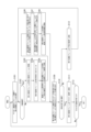
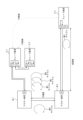
- FIG. 3 is a flowchart illustrating an example of a data communication method executed by the data communication system 1 according to the first embodiment. Note that the following steps S101 to S113 are data communication methods executed by the data communication system 1 in each communication frame transmission cycle (first cycle, second cycle, ..., or Xth cycle). It is.
- step S101 the master device 10 transmits a first communication frame to the highest slave device 20-1 or the relay device 30.
- step S102 it is determined whether the device that received the first communication frame from the master device 10 is the relay device 30. If the device is the relay device 30, the process advances to step S103. If the device is the slave device 20, the process advances to step S109.
- step S103 the relay device 30 copies the received first communication frame to create a second communication frame.
- step S104 the relay device 30 aligns the absolute time of the relay device 30 on the first communication cycle with the absolute time of the remote slave device 40 on the second communication cycle.
- step S105 the relay device 30 stores the second communication frame for discarded frame management, and transmits the second communication frame to the remote slave device 40 via the second control unit 34.
- step S106 the remote slave device 40 reads data stored in the second communication frame and writes data stored in the second communication frame.
- step S107 the relay device 30 writes the data dr (contents) written in the second communication frame into the memory 33A by adjusting the time to the transmission cycle of the first communication frame.
- step S108 the relay device 30 discards the second communication frame and updates the discarded frame management information.
- step S109 the slave device 20 reads the data stored in the first communication frame and writes the data stored in the first communication frame, and the relay device 30 reads the data stored in the first communication frame, and the relay device 30 reads the data stored in the first communication frame. Write dr to the first communication frame on the fly.
- step S110 it is determined whether the slave device 20 or the relay device 30 is the terminal (lowest stage) device. If it is a terminal device, the process advances to step S111. If the device is not a terminal device, the process advances to step S112.
- step S111 the slave device 20 or the relay device 30 returns the first communication frame to the master device 10.
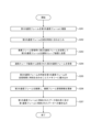
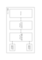
- FIG. 4 is a flowchart illustrating an example of a relay method executed by the relay device 30 according to the first embodiment.
- the flowchart in FIG. 4 more specifically explains the main relay method executed by the relay device 30 described in steps S103 to S109 in the flowchart in FIG.
- step S201 the copying unit 32 of the relay device 30 copies the received first communication frame to create a second communication frame.
- step S202 the first control unit 33 of the relay device 30 aligns the absolute time of the relay device 30 on the first communication cycle with the absolute time of the remote slave device 40 on the second communication cycle.
- step S205 the first control unit 33 of the relay device 30 writes the data dr (contents) written in the second communication frame into the memory 33A by adjusting the time to the transmission cycle of the first communication frame.
- step S207 the first control unit 33 of the relay device 30 writes the data dr written in the memory 33A into the first communication frame on the fly.
- FIG. 6 is a block diagram showing a configuration example of a relay device 30A according to the second embodiment.
- the relay device 30A includes an input/output section 31 (31-1 to 31-3), a duplication section 32, a first control section 33, a second control section 34, and a slave management section 35. and a memory management section 36.
- the relay device 30A according to the present embodiment is different from the relay device 30 according to the first embodiment in that it further includes a slave management section 35 and a memory management section 36.
- the same configurations as in the first embodiment are given the same reference numbers as in the first embodiment, and the description thereof will be omitted as appropriate.
- FIG. 8 is a block diagram showing a configuration example of a data communication system 1B according to the third embodiment.
- the data communication system 1B includes a master device 10, slave devices 20 (20-1 to 20-n), a relay device 30B, and remote slave devices 40 (40-1, 40-2). and.
- the data communication system 1B according to the present embodiment is different from the data communication system 1A according to the second embodiment in a place where one relay device 30B cannot perform short-cycle communication with each other (see FIG. The difference is that data communication is relayed between each of the two remote slave devices 40-1 and 40-2 installed at the slave installation locations SL1 and SL2).
- FIG. 8 is a block diagram showing a configuration example of a data communication system 1B according to the third embodiment.
- the data communication system 1B includes a master device 10, slave devices 20 (20-1 to 20-n), a relay device 30B, and remote slave devices 40 (40-1, 40-2). and.
- the data communication system 1B according to the present embodiment is different from the data communication system 1A
- FIG. 8 shows an example in which two remote slave devices 40-1 and 40-2 are installed at slave installation locations SL1 and SL2, respectively, three or more remote slave devices 40 (40-1 to 40- m) may be installed at locations (slave installation locations SL1 to SLm) where short-cycle communication cannot be performed with each other.
- the same configurations as in the second embodiment are given the same reference numbers as in the second embodiment, and the description thereof will be omitted as appropriate.
- the broadcast transmission unit 37 includes two or more input/output units 31-2 (31-2-1 to 31-2-m) and the second communication frame b transmitted from the second control unit 34, and two or more input/output units 31-2 (31-2-1 to 31-2-m)
- the second communication frame b is simultaneously transmitted to each of the.
- the broadcast transmitter 37 copies the second communication frames b for the number of copies to be sent via each of the input/output units 31-2.
- the relay device 30B includes, for example, an input/output section 31-2-1 connected to a remote slave device 40-1, and an input/output section 31-2 connected to a remote slave device 40-2. 2-2.
- the broadcast transmitting unit 37 copies one second communication frame and sends it to the remote slave devices 40-1 and 40-2, respectively, via the input/output units 31-2-1 to 31-2-2. to be sent at the same time.
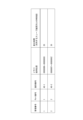
- FIG. 10 is a diagram showing a database managed by the slave management section 35 according to the third embodiment.
- the identification number of the remote slave device 40 the identification number of the remote slave device 40
- the memory usage position the communication time difference (difference time) with the opposing slave device 20
- the data to be managed is not limited to these.
- This embodiment differs from the second embodiment in that the relay device 30A is connected to a relay device 30B instead of being connected to a remote slave device 40-1; It is the same as the second embodiment in that data communication is relayed between the terminals 40-1 and 40-2.
- the relay device 30B differs from that of the third embodiment in that it is installed at the slave installation location SL1 instead of being installed at the master installation location ML, but it has two remote slave devices 40-1 and 40-2. This is the same as in the third embodiment in that data communication is relayed between each of them. However, in this embodiment, since the relay device 30B and the remote slave device 40-1 are installed at the same location, the communication between the relay device 30B and the remote slave device 40-1 is different from that in the third embodiment.
- a data communication system 1C according to the fourth embodiment is a combination of a data communication system 1A according to the second embodiment and a data communication system 1B according to the third embodiment.
- the master device 10 is connected to two or more remote slaves installed at a more remote installation location than in the second and third embodiments. It becomes possible to perform EtherCAT communication with the devices 40 (40-1 to 40-m).
- FIG. 12 is a block diagram showing a configuration example of a data communication system 1D according to the fifth embodiment.
- the data communication system 1D includes a master device 10, slave devices 20 (20-1 to 20-n), a relay device 30, a remote slave device 40, and a pair of conversion devices 60 (60-n). -1, 60-2).
- the data communication system 1D according to the present embodiment has a pair of conversion devices 60 (60-1, The difference is that 60-2) is connected.
- the same configurations as in the first embodiment are given the same reference numbers as in the first embodiment, and the description thereof will be omitted as appropriate.
- EtherCAT communication (determined periodic communication) is performed within each area of the master installation location ML where the master device 10 etc. are located and the slave installation location SL where the remote slave device 40 is located. If a carrier network different from EtherCAT, such as TSN2, intervenes between the installation locations, EtherCAT communication is interrupted between the master device 10 and the remote slave device 40. Therefore, by inserting a pair of conversion devices 60 that convert the network communication protocol after the input/output section 31-2 of the relay device 30 and before the remote slave device 40, EtherCAT communication (determined periodic communication) is ensured and the communication is continued.
- a carrier network different from EtherCAT such as TSN2
- FIG. 13 is a diagram illustrating a conversion device that converts communication protocols between EtherCAT and TSN.
- the pair of conversion devices 60 (60-1, 60-2) receive the second communication frame from the relay device 30 or the remote slave device 40, the pair of conversion devices 60 (60-1, 60-2) convert the frame format of the second communication frame from the EtherCAT communication frame format to the time.
- the second communication frame is converted into a frame format of a predetermined network that allows synchronous communication, and then transmitted to the predetermined network. Further, upon receiving the second communication frame from the predetermined network, the pair of conversion devices 60 (60-1, 60-2) convert the frame format of the second communication frame from the frame format of the predetermined network to the EtherCAT communication frame format.
- the second communication frame is converted into a frame format and transmitted to the relay device 30 or the remote slave device 40.
- the predetermined network is, for example, an Ethernet (registered trademark) communication network capable of time-synchronized communication, such as TSN (Time-Sensitive Networking), but is not limited to TSN.
- TSN is a network technology for interoperating industrial networks that extend standard Ethernet and IT networks.
- TSN is a network standard that is based on Ethernet, guarantees time synchronization, and can ensure real-time performance.
- the conversion device 60-1 transmits the communication frame received from, for example, TSN to a second input section 61-3, a second frame reading section 65, a second communication method conversion section 66, and a second transmission section 67. , and the second output unit 61-4 to the relay device 30.
- the conversion device 60-2 has the same functions and configuration as the conversion device 60-1, so a description thereof will be omitted.
- the first communication method conversion unit 63 converts the communication protocol from EtherCAT to Ethernet. Conversion of the communication protocol is necessary in order to transmit the communication frame received from the relay device 30 to the remote slave device 40 via TSN2, which uses a communication method different from EtherCAT.
- the first output unit 61-2 is an output port that outputs communication frames from the conversion device 60-1 to the TSN2.
- the first output unit 61-2 is composed of a physical layer transceiver device (EtherPHY) for transmitting and receiving communication frames.
- EtherPHY physical layer transceiver device
- the second input unit 61-3 is an input port that inputs communication frames from the TSN2.
- the first input unit 61-1 is constituted by a physical layer transceiver device (EtherPHY) for transmitting and receiving communication frames.
- EtherPHY physical layer transceiver device
- the second frame reading unit 65 reads data written in the received communication frame from the TSN 2 via the second input unit 61-3.
- the second frame reading section 65 transmits the time information and communication information of the communication frame to the cycle time holding function section 68.
- the second communication method conversion unit 66 converts the communication protocol from Ethernet to EtherCAT. Conversion of the communication protocol is necessary because the communication frame received from the TSN 2 is transmitted to the relay device 30 using EtherCAT, which has a different communication method from Ethernet.
- the second transmitting unit 67 transmits the communication frame received from the TSN 2 to the relay device 30 via the second output unit 61-4 using the EtherCAT communication protocol.
- the second output unit 61-4 is an output port that outputs communication frames from the conversion device 60-1 to the relay device 30.
- the second output unit 61-4 is configured by a physical layer transceiver device (EtherPHY) for transmitting and receiving communication frames.
- EtherPHY physical layer transceiver device
- the cycle time holding function section 68 receives time information and communication information of communication frames from the first frame reading section 62 and the second frame reading section 65, and instructs the second transmitting section 67 about the communication cycle time.
- the communication cycle time refers to, for example, the time from processing data communication to the relay device 30 or remote slave device 40 until processing data communication to the same device again.
- the conversion device 60 converts the communication protocol between EtherCAT and Ethernet, so that the master device 10 can perform EtherCAT communication with the remote slave device 40 across a carrier network such as TSN. It becomes possible.
- FIG. 15 is a block diagram showing a configuration example of a data communication system 1E according to the sixth embodiment.
- the data communication system 1E includes a master device 10, slave devices 20 (20-1 to 20-n), a relay device 30A, and remote slave devices 40 (40-1 to 40-m). and a pair of conversion devices 60 (60-1, 60-2).
- the data communication system 1E according to the present embodiment has one pair of connections between the relay device 30A and the remote slave devices 40 (40-1 to 40-m). The difference is that converters 60 (60-1, 60-2) are connected.
- the same configurations as in the second embodiment are given the same reference numbers as in the second embodiment, and the description thereof will be omitted as appropriate.
- the data communication system 1E is connected to the rear stage of the input/output unit 31-2 of the relay device 30A and the remote slave device 40-1 of the data communication system 1A according to the second embodiment.
- a pair of conversion devices 60 for converting the network communication protocol are inserted in the front stage of the input/output section to ensure EtherCAT communication (determined cycle communication) between the master and slave and continue the communication.
- the conversion device 60 converts the communication protocol between EtherCAT and Ethernet, so that the master device 10 can perform EtherCAT communication with the remote slave device 40 across a carrier network such as TSN. It becomes possible.
- FIG. 16 is a block diagram showing a configuration example of a data communication system 1F according to the seventh embodiment.
- the data communication system 1F includes a master device 10, slave devices 20 (20-1 to 20-n), a relay device 30B, and remote slave devices 40 (40-1, 40-2). and a pair of conversion devices 60 ((60-1, 60-2) and (60-3, 60-4)).
- the data communication system 1F according to the present embodiment has a pair of The difference is that converters 60 (60-1, 60-2, 60-3, 60-4) are connected.
- the same configurations as in the third embodiment are given the same reference numbers as in the third embodiment, and the description thereof will be omitted as appropriate.
- the data communication system 1F is connected to the rear stage of the input/output unit 31-2-1 of the relay device 30B of the data communication system 1B according to the third embodiment and the remote slave device 40-
- a pair of conversion devices 60 that convert the network communication protocol to the front stage of the input/output unit of the relay device 30B, the rear stage of the input/output unit 31-2-2 of the relay device 30B, and the front stage of the input/output unit of the remote slave device 40-2. are inserted, EtherCAT communication (determined cycle communication) between the master and slave is ensured, and the communication is continued.
- the conversion device 60 converts the communication protocol between EtherCAT and Ethernet, so that the master device 10 can perform EtherCAT communication with the remote slave device 40 across a carrier network such as TSN. It becomes possible.
- FIG. 17 is a block diagram showing a configuration example of a data communication system 1G according to the eighth embodiment.
- the data communication system 1G includes a master device 10, slave devices 20 (20-1 to 20-n), a relay device 30A, a relay device 30B, and a remote slave device 40 (40-1). , 40-2) and a pair of conversion devices 60 ((60-1, 60-2) and (60-3, 60-4)).
- the data communication system 1G according to the present embodiment has a relay device 30A and a relay device 30B, a relay device 30B and a remote slave device 40 (40-1, 40- 2) in that a pair of conversion devices 60 are connected to each other.
- the same configurations as in the fourth embodiment are given the same reference numbers as in the fourth embodiment, and description thereof will be omitted as appropriate.
- the EtherCAT communication between the master and slave of the data communication system 1C according to the fourth embodiment is separated by a carrier network such as TSN
- a pair of conversions is performed.
- the master device 10 can perform EtherCAT communication with the remote slave device 40 across a carrier network such as TSN. Become.
- the computer 100 communicates with a processor 110, a ROM (Read Only Memory) 120, a RAM (Random Access Memory) 130, and a storage 140 as storage units, an input unit 150, an output unit 160, and An interface (I/F) 170 is provided.
- a processor 110 a ROM (Read Only Memory) 120
- a RAM Random Access Memory
- storage 140 storage units
- I/F An interface
- a data communication system that extends communication distance in EtherCAT communication, a master device that transmits a first communication frame in which data is stored to a slave device or a relay device in a first communication cycle; the slave device that reads and writes data to the first communication frame and transmits the first communication frame to the master device, a lower slave device, or the relay device;
- a second communication frame is created which is connected to the front or rear stage of the slave device, is a copy of the first communication frame received from the master device or the slave device, and data is transmitted to the second communication frame.
- the frame format of the second communication frame is converted from the frame format of the predetermined network to the frame format of the EtherCAT communication, and the second communication frame is
- the data communication system further comprises a pair of converting devices for transmitting the data to the relay device or the remote slave device.
- a relay device that relays between communications with different communication cycles in EtherCAT communication, creating a second communication frame that is a duplicate of the received first communication frame; reading and writing data stored in the second communication frame, and aligning the absolute time of the relay device on the first communication cycle with the absolute time of the remote slave device on the second communication cycle; The data written in the second communication frame received from the remote slave device in the second communication cycle is transferred to the first communication frame, and the data written in the second communication frame received from the remote slave device in the second communication cycle is transferred to the master device or slave in the first communication cycle.
- a relay device including a controller that transmits data to a device.
- a data communication method for transmitting data to the master device or the slave device (Supplementary Note 8)
- a relay method for relaying communications with different communication cycles in EtherCAT communication comprising: By relay device, creating a second communication frame that is a duplicate of the received first communication frame; reading and writing data stored in the second communication frame; synchronizing the absolute time of the relay device on a first communication cycle with the absolute time of the remote slave device on a second communication cycle; The data written in the second communication frame received from the remote slave device in the second communication cycle is transferred to the first communication frame, and the data is sent to the master device or the slave device in the first communication cycle.
- Relay method to send Relay method to send.
- the replication unit 32 and first control unit 33 of the relay device 30, and the second control unit 34 may be configured as separate devices.
Landscapes
- Engineering & Computer Science (AREA)
- Computer Networks & Wireless Communication (AREA)
- Signal Processing (AREA)
- Quality & Reliability (AREA)
- Small-Scale Networks (AREA)
- Mobile Radio Communication Systems (AREA)
Abstract
Description
<データ通信システム>
図1は、第1の実施形態に係るデータ通信システム1の構成例を示すブロック図である。図1に示すように、データ通信システム1は、マスター装置10と、スレーブ装置20(20―1~20―n)と、中継装置30と、遠隔スレーブ装置40と、を備える。スレーブ装置20(20―1~20―n)は、1以上のスレーブ装置により構成することができる。遠隔スレーブ装置40と、スレーブ装置20とは同一の機能を有する。また、遠隔スレーブ装置40は、1以上設置可能であるため、遠隔スレーブ装置40-1~40-mとも表記する。データ通信システム1は、EtherCAT通信におけるマスター装置とスレーブ装置との間の通信距離を長延化する。
図2は、第1の実施形態に係る中継装置30の構成例を示すブロック図である。図2に示すように、中継装置30は、入出力部31(31―1~31―3)と、複製部32と、第1制御部33と、第2制御部34と、を備える。中継装置30は、EtherCAT通信において異なる通信周期間の通信を中継する。中継装置30は、図22に示す従来のスレーブ装置、あるいは図23に示す従来のブリッジ装置のブロック図と比較すると、複製部(Repeater)32を有することが顕著な違いである。本開示において、中継装置30は、複数のスレーブ装置20の後段に接続されているものとして説明を行うが、中継装置30は、マスター装置10及びマスター装置10に接続される複数のスレーブ装置20との間で短周期通信ができる圏内に配置されれば良く、スレーブ装置20の前段に配置されてもよいし、後段に配置されてもよい。複製部32と、第1制御部33と、第2制御部34とにより制御演算回路(コントローラ)50が構成される。制御演算回路50は、ASIC(Application Specific Integrated Circuit)、FPGA(Field-Programmable Gate Array)等の専用のハードウェアによって構成されてもよいし、プロセッサによって構成されてもよいし、双方を含んで構成されてもよい。
<データ通信システム>
図5は、第2の実施形態に係るデータ通信システム1Aの構成例を示すブロック図である。図5に示すように、データ通信システム1Aは、マスター装置10と、スレーブ装置20(20―1~20―n)と、中継装置30Aと、遠隔スレーブ装置40(40―1~40―m)と、を備える。遠隔スレーブ装置40は、1以上設置可能であるため、遠隔スレーブ装置40-1~40-mとも表記する。本実施形態に係るデータ通信システム1Aは、第1の実施形態に係るデータ通信システム1と比較して、1台の中継装置30Aが、相互に短周期通信可能な圏内(図5におけるスレーブ設置場所SL)に設置された2台以上の遠隔スレーブ装置40―1~40―mとの間でデータ通信を中継する点が相違する。第1の実施形態と同一の構成については、第1の実施形態と同一の参照番号を付して適宜説明を省略する。
図6は、第2の実施形態に係る中継装置30Aの構成例を示すブロック図である。図6に示すように、中継装置30Aは、入出力部31(31―1~31―3)と、複製部32と、第1制御部33と、第2制御部34と、スレーブ管理部35と、メモリー管理部36とを備える。本実施形態に係る中継装置30Aは、第1の実施形態に係る中継装置30と比較して、スレーブ管理部35及びメモリー管理部36を更に備える点が相違する。第1の実施形態と同一の構成については、第1の実施形態と同一の参照番号を付して適宜説明を省略する。複製部32と、第1制御部33と、第2制御部34と、スレーブ管理部35と、メモリー管理部36とにより制御演算回路(コントローラ)50Aが構成される。制御演算回路50Aは、ASIC、FPGA等の専用のハードウェアによって構成されてもよいし、プロセッサによって構成されてもよいし、双方を含んで構成されてもよい。
<データ通信システム>
図8は、第3の実施形態に係るデータ通信システム1Bの構成例を示すブロック図である。図8に示すように、データ通信システム1Bは、マスター装置10と、スレーブ装置20(20―1~20―n)と、中継装置30Bと、遠隔スレーブ装置40(40―1,40―2)と、を備える。本実施形態に係るデータ通信システム1Bは、第2の実施形態に係るデータ通信システム1Aと比較して、1台の中継装置30Bが、相互に短周期通信をすることが出来ない場所(図8におけるスレーブ設置場所SL1及びSL2)に設置された2台の遠隔スレーブ装置40―1,40―2のそれぞれとの間でデータ通信を中継する点が相違する。図8では、遠隔スレーブ装置40―1及び40―2の2台が、それぞれスレーブ設置場所SL1及びSL2に設置された例を示すが、3台以上の遠隔スレーブ装置40(40―1~40―m)が、相互に短周期通信をすることが出来ない場所(スレーブ設置場所SL1~SLm)に設置されていてもよい。第2の実施形態と同一の構成については、第2の実施形態と同一の参照番号を付して適宜説明を省略する。
図9は、第3の実施形態に係る中継装置30Bの構成例を示すブロック図である。図9に示すように、中継装置30Bは、入出力部31―1,31-2(31-2-1~31-2-m),31―3と、複製部32と、第1制御部33と、第2制御部34と、スレーブ管理部35と、メモリー管理部36と、同報送信部37とを備える。本実施形態に係る中継装置30Bは、第1の実施形態に係る中継装置30Aと比較して、複数の入出力部31-2(31-2-1~31-2-m)と、同報送信部37とを更に備える点が相違する。第2の実施形態と同一の構成については、第2の実施形態と同一の参照番号を付して適宜説明を省略する。複製部32と、第1制御部33と、第2制御部34と、スレーブ管理部35と、メモリー管理部36と、同報送信部37とにより制御演算回路(コントローラ)50Bが構成される。制御演算回路50Bは、ASIC、FPGA等の専用のハードウェアによって構成されてもよいし、プロセッサによって構成されてもよいし、双方を含んで構成されてもよい。
<データ通信システム>
図11は、第4の実施形態に係るデータ通信システム1Cの構成例を示すブロック図である。図11に示すように、データ通信システム1Cは、マスター装置10と、スレーブ装置20(20―1~20―n)と、中継装置30Aと、中継装置30Bと、遠隔スレーブ装置40(40―1,40―2)と、を備える。本実施形態に係るデータ通信システム1Cは、第3の実施形態に係るデータ通信システム1Bと比較して、中継装置30A、及び中継装置30Bの双方を備えている点が相違する。本実施形態では、中継装置30Aは、遠隔スレーブ装置40―1と接続される代わりに、中継装置30Bと接続されている点で第2の実施形態のものと異なるが、2台の遠隔スレーブ装置40―1,40―2との間でデータ通信を中継する点では第2の実施形態のものと同じである。中継装置30Bは、マスター設置場所MLに設置される代わりに、スレーブ設置場所SL1に設置される点で第3の実施形態のものと異なるが、2台の遠隔スレーブ装置40―1,40―2のそれぞれとの間でデータ通信を中継する点では第3の実施形態のものと同じである。ただし、本実施形態では、中継装置30Bと遠隔スレーブ装置40―1とが同じ場所に設置されているため、中継装置30Bと遠隔スレーブ装置40―1との間の通信は、第3の実施形態のような長周期通信ではなく、短周期通信になる。なお、図11では、遠隔スレーブ装置40―1及び40―2の2台が、それぞれスレーブ設置場所SL1及びSL2に設置された例を示すが、3台以上の遠隔スレーブ装置40(40―1~40―m)が、相互に短周期通信をすることが出来ない場所(スレーブ設置場所SL1~SLm)に設置されていてもよい。第3の実施形態と同一の構成については、第3の実施形態と同一の参照番号を付して適宜説明を省略する。
<データ通信システム>
図12は、第5の実施形態に係るデータ通信システム1Dの構成例を示すブロック図である。図12に示すように、データ通信システム1Dは、マスター装置10と、スレーブ装置20(20―1~20―n)と、中継装置30と、遠隔スレーブ装置40と、一対の変換装置60(60―1, 60―2)とを備える。本実施形態に係るデータ通信システム1Dは、第1の実施形態に係るデータ通信システム1と比較して、中継装置30と遠隔スレーブ装置40との間に、一対の変換装置60(60―1, 60―2)が接続されている点で相違する。第1の実施形態と同一の構成については、第1の実施形態と同一の参照番号を付して適宜説明を省略する。
図13は、EtherCATと、TSNとの間で、通信プロトコルを変換する変換装置を説明する図である。一対の変換装置60(60―1, 60―2)は、中継装置30又は遠隔スレーブ装置40から第2の通信フレームを受信すると、第2の通信フレームのフレーム形式をEtherCAT通信のフレーム形式から時刻同期通信が可能な所定のネットワークのフレーム形式に変換して、第2の通信フレームを所定のネットワークへ送信する。さらに、一対の変換装置60(60―1, 60―2)は、所定のネットワークから第2の通信フレームを受信すると、第2の通信フレームのフレーム形式を所定のネットワークのフレーム形式からEtherCAT通信のフレーム形式に変換して、第2の通信フレームを中継装置30又は遠隔スレーブ装置40へ送信する。所定のネットワークは、例えばTSN(Time-Sensitive Networking)などの、時刻同期通信が可能なEthernet(登録商標)の通信ネットワークであるが、TSNに限られない。TSNは、標準のEthernetを拡張する産業用ネットワークと、IT用ネットワークとを相互運用するためのネットワーク技術である。TSNは、Ethernetをベースにしながら、時刻の同期性が保証されており、リアルタイム性を担保できるネットワーク規格である。
<データ通信システム>
図15は、第6の実施形態に係るデータ通信システム1Eの構成例を示すブロック図である。図15に示すように、データ通信システム1Eは、マスター装置10と、スレーブ装置20(20―1~20―n)と、中継装置30Aと、遠隔スレーブ装置40(40―1~40―m)と、一対の変換装置60(60―1, 60―2)とを備える。本実施形態に係るデータ通信システム1Eは、第2の実施形態に係るデータ通信システム1Aと比較して、中継装置30Aと遠隔スレーブ装置40(40―1~40―m)との間に、一対の変換装置60(60―1, 60―2)が接続されている点で相違する。第2の実施形態と同一の構成については、第2の実施形態と同一の参照番号を付して適宜説明を省略する。
<データ通信システム>
図16は、第7の実施形態に係るデータ通信システム1Fの構成例を示すブロック図である。図16に示すように、データ通信システム1Fは、マスター装置10と、スレーブ装置20(20―1~20―n)と、中継装置30Bと、遠隔スレーブ装置40(40―1,40―2)と、一対の変換装置60((60―1,60―2)、及び(60―3,60―4))とを備える。本実施形態に係るデータ通信システム1Fは、第3の実施形態に係るデータ通信システム1Bと比較して、中継装置30Bと遠隔スレーブ装置40(40―1,40―2)との間に、一対の変換装置60(60―1,60―2,60―3,60―4)が接続されている点で相違する。第3の実施形態と同一の構成については、第3の実施形態と同一の参照番号を付して適宜説明を省略する。
<データ通信システム>
図17は、第8の実施形態に係るデータ通信システム1Gの構成例を示すブロック図である。図16に示すように、データ通信システム1Gは、マスター装置10と、スレーブ装置20(20―1~20―n)と、中継装置30Aと、中継装置30Bと、遠隔スレーブ装置40(40―1,40―2)と、一対の変換装置60((60―1,60―2)、及び(60―3,60―4))とを備える。本実施形態に係るデータ通信システム1Gは、第4の実施形態に係るデータ通信システム1Cと比較して、中継装置30Aと中継装置30B、中継装置30Bと遠隔スレーブ装置40(40―1,40―2)との間に、一対の変換装置60がそれぞれ接続されている点で相違する。第4の実施形態と同一の構成については、第4の実施形態と同一の参照番号を付して適宜説明を省略する。
EtherCAT通信における通信距離を長延化するデータ通信システムであって、
第1の通信周期で、データが格納された第1の通信フレームをスレーブ装置又は中継装置に送信するマスター装置と、
前記第1の通信フレームに対し、データの読み取り及び書き込みを行い、前記マスター装置、下段のスレーブ装置又は前記中継装置に前記第1の通信フレームを送信する前記スレーブ装置と、
前記スレーブ装置の前段又は後段に接続され、前記マスター装置又は前記スレーブ装置より受信した前記第1の通信フレームを複製した第2の通信フレームを作成し、前記第2の通信フレームに対し、データの読み取り及び書き込みを行い、前記第1の通信周期上の前記中継装置の絶対時刻と第2の通信周期上の遠隔スレーブ装置の絶対時刻との合わせこみを行い、前記第2の通信周期で前記第2の通信フレームを前記遠隔スレーブ装置に送信し、前記遠隔スレーブ装置より前記第2の通信周期で受信した前記第2の通信フレームに書き込まれたデータを前記第1の通信フレームに載せ替えて、前記第1の通信周期で前記マスター装置又は前記スレーブ装置へ送信する前記中継装置と、
前記中継装置より受信した前記第2の通信フレームに対し、データの読み取り及び書き込みを行い、前記中継装置に前記第2の通信フレームを返送する、前記遠隔スレーブ装置と、
を備えるデータ通信システム。
(付記項2)
付記項1に記載のデータ通信システムであって、
前記中継装置又は前記遠隔スレーブ装置から前記第2の通信フレームを受信すると、前記第2の通信フレームのフレーム形式を前記EtherCAT通信のフレーム形式から時刻同期通信が可能な所定のネットワークのフレーム形式に変換して、前記第2の通信フレームを前記所定のネットワークへ送信し、
前記所定のネットワークから前記第2の通信フレームを受信すると、前記第2の通信フレームのフレーム形式を前記所定のネットワークのフレーム形式から前記EtherCAT通信のフレーム形式に変換して、前記第2の通信フレームを前記中継装置又は前記遠隔スレーブ装置へ送信する、一対の変換装置を更に備える、データ通信システム。
(付記項3)
EtherCAT通信において異なる通信周期の通信間を中継する中継装置であって、
受信した第1の通信フレームを複製した第2の通信フレームを作成し、
前記第2の通信フレームに格納されたデータの読み取り及び書き込みを行い、第1の通信周期上の前記中継装置の絶対時刻と第2の通信周期上の遠隔スレーブ装置の絶対時刻との合わせこみを行い、前記遠隔スレーブ装置より前記第2の通信周期で受信した前記第2の通信フレームに書き込まれたデータを前記第1の通信フレームに載せ替えて、前記第1の通信周期でマスター装置又はスレーブ装置へ送信を行うコントローラ、を備える中継装置。
(付記項4)
付記項3に記載の中継装置であって、
前記コントローラは、更に、前記第1の通信周期でデータの送受信を行う前記スレーブ装置に代わり、前記第2の通信周期で、前記遠隔スレーブ装置との間で、前記第2の通信フレームの送受信を行う、中継装置。
(付記項5)
付記項4に記載の中継装置であって、
前記コントローラは、更に、2台以上の遠隔スレーブ装置に接続され、前記2台以上の遠隔スレーブ装置のそれぞれに割り当てるメモリー上のメモリー使用位置を管理し、前記メモリー上の前記メモリー使用位置で、前記2台以上の遠隔スレーブ装置のそれぞれから受信したデータの書き込み及び読み取りを行う、中継装置。
(付記項6)
付記項5に記載の中継装置であって、
前記2台以上の遠隔スレーブ装置のそれぞれと一対一に接続される、2つ以上のインターフェースを更に備え、
前記コントローラは、更に、前記第2の通信フレームを複製し、前記2つ以上のインターフェースのそれぞれに、前記第2の通信フレームを同時に送信する、中継装置。
(付記項7)
EtherCAT通信における通信距離を長延化するデータ通信方法であって、
マスター装置により、第1の通信周期で、データが格納された第1の通信フレームをスレーブ装置又は中継装置に送信し、
前記スレーブ装置により、前記第1の通信フレームに対し、データの読み取り及び書き込みを行い、
前記スレーブ装置により、前記マスター装置、後段のスレーブ装置又は前記中継装置に前記第1の通信フレームを送信し、
前記中継装置により、前記マスター装置又は前記スレーブ装置より受信した前記第1の通信フレームを複製した第2の通信フレームを作成し、
前記中継装置により、前記第2の通信フレームに対し、データの読み取り及び書き込みを行い、
前記中継装置により、前記第1の通信周期上の前記中継装置の絶対時刻と第2の通信周期上の遠隔スレーブ装置の絶対時刻との合わせこみを行い、
前記中継装置により、前記第2の通信周期で前記第2の通信フレームを前記遠隔スレーブ装置に送信し、
前記遠隔スレーブ装置により、前記中継装置より受信した前記第2の通信フレームに対し、データの読み取り及び書き込みを行い、
前記遠隔スレーブ装置により、前記中継装置に前記第2の通信フレームを返送し、
前記中継装置により、前記遠隔スレーブ装置より前記第2の通信周期で受信した前記第2の通信フレームに書き込まれたデータを、前記第1の通信フレームに載せ替えて、前記第1の通信周期で前記マスター装置又は前記スレーブ装置へ送信するデータ通信方法。
(付記項8)
EtherCAT通信において異なる通信周期の通信間を中継する中継方法であって、
中継装置により、
受信した第1の通信フレームを複製した第2の通信フレームを作成し、
前記第2の通信フレームに格納されたデータの読み取り及び書き込みを行い、
第1の通信周期上の前記中継装置の絶対時刻と第2の通信周期上の遠隔スレーブ装置の絶対時刻との合わせこみを行い、
前記遠隔スレーブ装置より前記第2の通信周期で受信した前記第2の通信フレームに書き込まれたデータを前記第1の通信フレームに載せ替えて、前記第1の通信周期でマスター装置又はスレーブ装置へ送信する中継方法。
(付記項9)
付記項8に記載の中継方法であって、
前記第1の通信周期でデータの送受信を行う前記スレーブ装置に代わり、前記第2の通信周期で、前記遠隔スレーブ装置との間で、前記第2の通信フレームの送受信を行う、中継方法。
(付記項10)
コンピュータによって実行可能なプログラムを記憶した非一時的記憶媒体であって、前記コンピュータを付記項3から6のいずれか一項に記載の中継装置として機能させるプログラムを記憶した非一時的記憶媒体。
2 キャリアネットワーク(TSN)
10 マスター装置
20(20-1~20-n) スレーブ装置
30,30A,30B 中継装置(代理スレーブ)
31,31-1,31-2,31-2-1~31-2-m,31-3 入出力部(インターフェース)
32 複製部(Repeater)
33 第1制御部(Slave Controller)
33A メモリー
34 第2制御部(Proxy)
35 スレーブ管理部
36 メモリー管理部
37 同報送信部
40,40-1~40-m 遠隔スレーブ装置
50,50A,50B 制御演算回路(コントローラ)
60,60-1~60-4 変換装置
100 コンピュータ
110 プロセッサ
120 ROM
130 RAM
140 ストレージ
150 入力部
160 出力部
170 通信インターフェース(I/F)
180 バス
Claims (10)
- EtherCAT通信における通信距離を長延化するデータ通信システムであって、
第1の通信周期で、データが格納された第1の通信フレームをスレーブ装置又は中継装置に送信するマスター装置と、
前記第1の通信フレームに対し、データの読み取り及び書き込みを行い、前記マスター装置、下段のスレーブ装置又は前記中継装置に前記第1の通信フレームを送信する前記スレーブ装置と、
前記スレーブ装置の前段又は後段に接続され、前記マスター装置又は前記スレーブ装置より受信した前記第1の通信フレームを複製した第2の通信フレームを作成し、前記第2の通信フレームに対し、データの読み取り及び書き込みを行い、前記第1の通信周期上の前記中継装置の絶対時刻と第2の通信周期上の遠隔スレーブ装置の絶対時刻との合わせこみを行い、前記第2の通信周期で前記第2の通信フレームを前記遠隔スレーブ装置に送信し、前記遠隔スレーブ装置より前記第2の通信周期で受信した前記第2の通信フレームに書き込まれたデータを前記第1の通信フレームに載せ替えて、前記第1の通信周期で前記マスター装置又は前記スレーブ装置へ送信する前記中継装置と、
前記中継装置より受信した前記第2の通信フレームに対し、データの読み取り及び書き込みを行い、前記中継装置に前記第2の通信フレームを返送する、前記遠隔スレーブ装置と、
を備えるデータ通信システム。 - 請求項1に記載のデータ通信システムであって、
前記中継装置又は前記遠隔スレーブ装置から前記第2の通信フレームを受信すると、前記第2の通信フレームのフレーム形式を前記EtherCAT通信のフレーム形式から時刻同期通信が可能な所定のネットワークのフレーム形式に変換して、前記第2の通信フレームを前記所定のネットワークへ送信し、
前記所定のネットワークから前記第2の通信フレームを受信すると、前記第2の通信フレームのフレーム形式を前記所定のネットワークのフレーム形式から前記EtherCAT通信のフレーム形式に変換して、前記第2の通信フレームを前記中継装置又は前記遠隔スレーブ装置へ送信する、一対の変換装置を更に備える、データ通信システム。 - EtherCAT通信において異なる通信周期の通信間を中継する中継装置であって、
受信した第1の通信フレームを複製した第2の通信フレームを作成する複製部と、
前記第2の通信フレームに格納されたデータの読み取り及び書き込みを行い、第1の通信周期上の前記中継装置の絶対時刻と第2の通信周期上の遠隔スレーブ装置の絶対時刻との合わせこみを行い、前記遠隔スレーブ装置より前記第2の通信周期で受信した前記第2の通信フレームに書き込まれたデータを前記第1の通信フレームに載せ替えて、前記第1の通信周期でマスター装置又はスレーブ装置へ送信する第1制御部と、
を備える中継装置。 - 請求項3に記載の中継装置であって、
前記第1の通信周期でデータの送受信を行う前記スレーブ装置に代わり、前記第2の通信周期で、前記遠隔スレーブ装置との間で、前記第2の通信フレームの送受信を行う第2制御部を更に備える、中継装置。 - 請求項4に記載の中継装置であって、
2台以上の遠隔スレーブ装置に接続され、
前記2台以上の遠隔スレーブ装置のそれぞれに割り当てるメモリー上のメモリー使用位置を管理するスレーブ管理部と、
前記第1制御部に対し、前記メモリー上の前記メモリー使用位置で、前記2台以上の遠隔スレーブ装置のそれぞれから受信したデータの書き込み及び読み取りを行うように、指示を行うメモリー管理部と、
を更に備える中継装置。 - 請求項5に記載の中継装置であって、
前記2台以上の遠隔スレーブ装置のそれぞれと一対一に接続された2つ以上の入出力部と、
前記第2制御部より送信される前記第2の通信フレームを複製し、前記2つ以上の入出力部のそれぞれに、前記第2の通信フレームを同時に送信する同報送信部と、
を更に備える、中継装置。 - EtherCAT通信における通信距離を長延化するデータ通信方法であって、
マスター装置により、第1の通信周期で、データが格納された第1の通信フレームをスレーブ装置又は中継装置に送信するステップと、
前記スレーブ装置により、前記第1の通信フレームに対し、データの読み取り及び書き込みを行うステップと、
前記スレーブ装置により、前記マスター装置、後段のスレーブ装置又は前記中継装置に前記第1の通信フレームを送信するステップと、
前記中継装置により、前記マスター装置又は前記スレーブ装置より受信した前記第1の通信フレームを複製した第2の通信フレームを作成するステップと、
前記中継装置により、前記第2の通信フレームに対し、データの読み取り及び書き込みを行うステップと、
前記中継装置により、前記第1の通信周期上の前記中継装置の絶対時刻と第2の通信周期上の遠隔スレーブ装置の絶対時刻との合わせこみを行うステップと、
前記中継装置により、前記第2の通信周期で前記第2の通信フレームを前記遠隔スレーブ装置に送信するステップと、
前記遠隔スレーブ装置により、前記中継装置より受信した前記第2の通信フレームに対し、データの読み取り及び書き込みを行うステップと、
前記遠隔スレーブ装置により、前記中継装置に前記第2の通信フレームを返送するステップと、
前記中継装置により、前記遠隔スレーブ装置より前記第2の通信周期で受信した前記第2の通信フレームに書き込まれたデータを、前記第1の通信フレームに載せ替えて、前記第1の通信周期で前記マスター装置又は前記スレーブ装置へ送信するステップと、
を実行するデータ通信方法。 - EtherCAT通信において異なる通信周期の通信間を中継する中継方法であって、
中継装置により、
受信した第1の通信フレームを複製した第2の通信フレームを作成するステップと、
前記第2の通信フレームに格納されたデータの読み取り及び書き込みを行うステップと、
第1の通信周期上の前記中継装置の絶対時刻と第2の通信周期上の遠隔スレーブ装置の絶対時刻との合わせこみを行うステップと、
前記遠隔スレーブ装置より前記第2の通信周期で受信した前記第2の通信フレームに書き込まれたデータを前記第1の通信フレームに載せ替えて、前記第1の通信周期でマスター装置又はスレーブ装置へ送信するステップと、
を実行する中継方法。 - 請求項8に記載の中継方法であって、
前記第1の通信周期でデータの送受信を行う前記スレーブ装置に代わり、前記第2の通信周期で、前記遠隔スレーブ装置との間で、前記第2の通信フレームの送受信を行うステップを更に実行する、中継方法。 - コンピュータを、請求項3から6のいずれか一項に記載の中継装置として機能させるためのプログラム。
Priority Applications (2)
| Application Number | Priority Date | Filing Date | Title |
|---|---|---|---|
| US18/872,145 US20250358145A1 (en) | 2022-06-07 | 2023-04-12 | Data communication system, data communication method, relay device, relay method, and program |
| JP2024526258A JP7769269B2 (ja) | 2022-06-07 | 2023-04-12 | データ通信システム、データ通信方法、中継装置、中継方法、及びプログラム |
Applications Claiming Priority (2)
| Application Number | Priority Date | Filing Date | Title |
|---|---|---|---|
| JPPCT/JP2022/023016 | 2022-06-07 | ||
| PCT/JP2022/023016 WO2023238255A1 (ja) | 2022-06-07 | 2022-06-07 | データ通信システム、データ通信方法、中継装置、中継方法、及びプログラム |
Publications (1)
| Publication Number | Publication Date |
|---|---|
| WO2023238501A1 true WO2023238501A1 (ja) | 2023-12-14 |
Family
ID=89117722
Family Applications (2)
| Application Number | Title | Priority Date | Filing Date |
|---|---|---|---|
| PCT/JP2022/023016 Ceased WO2023238255A1 (ja) | 2022-06-07 | 2022-06-07 | データ通信システム、データ通信方法、中継装置、中継方法、及びプログラム |
| PCT/JP2023/014927 Ceased WO2023238501A1 (ja) | 2022-06-07 | 2023-04-12 | データ通信システム、データ通信方法、中継装置、中継方法、及びプログラム |
Family Applications Before (1)
| Application Number | Title | Priority Date | Filing Date |
|---|---|---|---|
| PCT/JP2022/023016 Ceased WO2023238255A1 (ja) | 2022-06-07 | 2022-06-07 | データ通信システム、データ通信方法、中継装置、中継方法、及びプログラム |
Country Status (3)
| Country | Link |
|---|---|
| US (1) | US20250358145A1 (ja) |
| JP (1) | JP7769269B2 (ja) |
| WO (2) | WO2023238255A1 (ja) |
Families Citing this family (1)
| Publication number | Priority date | Publication date | Assignee | Title |
|---|---|---|---|---|
| CN120848442B (zh) * | 2025-09-25 | 2025-11-28 | 临海市新睿电子科技股份有限公司 | 一种EtherCAT实时性提高方法、系统、存储介质及程序产品 |
Citations (6)
| Publication number | Priority date | Publication date | Assignee | Title |
|---|---|---|---|---|
| JP2013197656A (ja) * | 2012-03-16 | 2013-09-30 | Hitachi Ltd | 制御系システムおよびその制御系システムに用いられる代理スレーブ、代理マスタ、ならびに、制御方法 |
| JP2018128724A (ja) * | 2017-02-06 | 2018-08-16 | オムロン株式会社 | 通信装置、通信システム |
| CN112147927A (zh) * | 2020-09-11 | 2020-12-29 | 苏州谷夫道自动化科技有限公司 | 一种双通道总线通信的多轴运动控制系统 |
| JP2021117569A (ja) * | 2020-01-23 | 2021-08-10 | 株式会社キーエンス | データ中継装置および表示装置 |
| JP2021170311A (ja) * | 2020-04-14 | 2021-10-28 | 寧波弘訊科技股▲ふん▼有限公司 | EtherCATマスタースレーブ統合ブリッジコントローラー及び制御方法 |
| CN114285695A (zh) * | 2021-12-24 | 2022-04-05 | 深圳市汇川技术股份有限公司 | 通信方法、装置、设备、系统和存储介质 |
-
2022
- 2022-06-07 WO PCT/JP2022/023016 patent/WO2023238255A1/ja not_active Ceased
-
2023
- 2023-04-12 JP JP2024526258A patent/JP7769269B2/ja active Active
- 2023-04-12 WO PCT/JP2023/014927 patent/WO2023238501A1/ja not_active Ceased
- 2023-04-12 US US18/872,145 patent/US20250358145A1/en active Pending
Patent Citations (6)
| Publication number | Priority date | Publication date | Assignee | Title |
|---|---|---|---|---|
| JP2013197656A (ja) * | 2012-03-16 | 2013-09-30 | Hitachi Ltd | 制御系システムおよびその制御系システムに用いられる代理スレーブ、代理マスタ、ならびに、制御方法 |
| JP2018128724A (ja) * | 2017-02-06 | 2018-08-16 | オムロン株式会社 | 通信装置、通信システム |
| JP2021117569A (ja) * | 2020-01-23 | 2021-08-10 | 株式会社キーエンス | データ中継装置および表示装置 |
| JP2021170311A (ja) * | 2020-04-14 | 2021-10-28 | 寧波弘訊科技股▲ふん▼有限公司 | EtherCATマスタースレーブ統合ブリッジコントローラー及び制御方法 |
| CN112147927A (zh) * | 2020-09-11 | 2020-12-29 | 苏州谷夫道自动化科技有限公司 | 一种双通道总线通信的多轴运动控制系统 |
| CN114285695A (zh) * | 2021-12-24 | 2022-04-05 | 深圳市汇川技术股份有限公司 | 通信方法、装置、设备、系统和存储介质 |
Non-Patent Citations (1)
| Title |
|---|
| VON HOYNINGEN-HUENE JOHANNES; MUELLER ANDREAS; DIETRICH STEVEN; MAY GUNTHER: "Comparison of wireless gateway concepts for industrial real-time-communication", 2016 IEEE 21ST INTERNATIONAL CONFERENCE ON EMERGING TECHNOLOGIES AND FACTORY AUTOMATION (ETFA), IEEE, 6 September 2016 (2016-09-06), pages 1 - 4, XP032994533, DOI: 10.1109/ETFA.2016.7733597 * |
Also Published As
| Publication number | Publication date |
|---|---|
| JP7769269B2 (ja) | 2025-11-13 |
| US20250358145A1 (en) | 2025-11-20 |
| WO2023238255A1 (ja) | 2023-12-14 |
| JPWO2023238501A1 (ja) | 2023-12-14 |
Similar Documents
| Publication | Publication Date | Title |
|---|---|---|
| EP2816425B1 (en) | Control device, image processing device, control method, computer-readable recording medium, and program | |
| CN101164264B (zh) | 用于对两个总线系统进行同步的方法和设备以及由两个总线系统组成的装置 | |
| CN114174953B (zh) | 低复杂度以太网节点(len)一个端口 | |
| US11929848B2 (en) | Bus converter | |
| JP5127482B2 (ja) | タイミング同期方法、同期装置、同期システム及び同期プログラム | |
| EP3561680B1 (en) | Rpc conversion process system and rpc conversion method | |
| KR20230152021A (ko) | 양자 컴퓨터용 데이터 처리 장치 네트워크 제어 | |
| WO2023238501A1 (ja) | データ通信システム、データ通信方法、中継装置、中継方法、及びプログラム | |
| JP2013168811A (ja) | ネットワークシステム及び時刻同期方法 | |
| CN113742424A (zh) | 基于rpa的自然资源一体化跨网动态表单数据同步方法 | |
| JP2011165185A (ja) | タイムトリガ型バスシステムの作動方法 | |
| JP2015115864A (ja) | データ転送システム及びデータ転送システムの制御方法 | |
| Ayavoo et al. | Two novel shared-clock scheduling algorithms for use with ‘Controller Area Network’and related protocols | |
| CN114868347B (zh) | 对通过无线链路的数据业务的冗余控制 | |
| JP6805938B2 (ja) | 仮想lanの時刻同期方法 | |
| US20110138099A1 (en) | Method for communicating between nodes and server apparatus | |
| Dietrich et al. | Frame conversion schemes for cascaded wired/wireless communication networks of factory automation | |
| JP4995177B2 (ja) | Nat装置 | |
| CN214627023U (zh) | 一种兼容可定义确定性通信以太网的交换设备 | |
| JP2010183270A (ja) | 通信制御回路、通信ノード、通信システム、並びに通信制御方法及びプログラム | |
| JP6493756B2 (ja) | 送信装置、受信装置、送受信システムおよびプログラム | |
| Das et al. | Multi-loop networked process control: A synchronized approach | |
| CN114301566B (zh) | 冗余系统的时钟同步方法、冗余系统及网络系统 | |
| JP5168182B2 (ja) | 入出力データ転送方式 | |
| WO2024214228A1 (ja) | 変換装置、データ通信システム、変換方法、及びプログラム |
Legal Events
| Date | Code | Title | Description |
|---|---|---|---|
| 121 | Ep: the epo has been informed by wipo that ep was designated in this application |
Ref document number: 23819488 Country of ref document: EP Kind code of ref document: A1 |
|
| WWE | Wipo information: entry into national phase |
Ref document number: 2024526258 Country of ref document: JP |
|
| NENP | Non-entry into the national phase |
Ref country code: DE |
|
| 122 | Ep: pct application non-entry in european phase |
Ref document number: 23819488 Country of ref document: EP Kind code of ref document: A1 |
|
| WWP | Wipo information: published in national office |
Ref document number: 18872145 Country of ref document: US |