WO2023229008A1 - マンホール構造体、多重殻タンク及び船舶 - Google Patents
マンホール構造体、多重殻タンク及び船舶 Download PDFInfo
- Publication number
- WO2023229008A1 WO2023229008A1 PCT/JP2023/019505 JP2023019505W WO2023229008A1 WO 2023229008 A1 WO2023229008 A1 WO 2023229008A1 JP 2023019505 W JP2023019505 W JP 2023019505W WO 2023229008 A1 WO2023229008 A1 WO 2023229008A1
- Authority
- WO
- WIPO (PCT)
- Prior art keywords
- manhole
- tank
- cover
- shell
- wall
- Prior art date
- Legal status (The legal status is an assumption and is not a legal conclusion. Google has not performed a legal analysis and makes no representation as to the accuracy of the status listed.)
- Ceased
Links
Images





Classifications
-
- B—PERFORMING OPERATIONS; TRANSPORTING
- B63—SHIPS OR OTHER WATERBORNE VESSELS; RELATED EQUIPMENT
- B63B—SHIPS OR OTHER WATERBORNE VESSELS; EQUIPMENT FOR SHIPPING
- B63B25/00—Load-accommodating arrangements, e.g. stowing, trimming; Vessels characterised thereby
- B63B25/02—Load-accommodating arrangements, e.g. stowing, trimming; Vessels characterised thereby for bulk goods
- B63B25/08—Load-accommodating arrangements, e.g. stowing, trimming; Vessels characterised thereby for bulk goods fluid
- B63B25/12—Load-accommodating arrangements, e.g. stowing, trimming; Vessels characterised thereby for bulk goods fluid closed
- B63B25/16—Load-accommodating arrangements, e.g. stowing, trimming; Vessels characterised thereby for bulk goods fluid closed heat-insulated
-
- B—PERFORMING OPERATIONS; TRANSPORTING
- B63—SHIPS OR OTHER WATERBORNE VESSELS; RELATED EQUIPMENT
- B63B—SHIPS OR OTHER WATERBORNE VESSELS; EQUIPMENT FOR SHIPPING
- B63B19/00—Arrangements or adaptations of ports, doors, windows, port-holes, or other openings or covers
-
- B—PERFORMING OPERATIONS; TRANSPORTING
- B65—CONVEYING; PACKING; STORING; HANDLING THIN OR FILAMENTARY MATERIAL
- B65D—CONTAINERS FOR STORAGE OR TRANSPORT OF ARTICLES OR MATERIALS, e.g. BAGS, BARRELS, BOTTLES, BOXES, CANS, CARTONS, CRATES, DRUMS, JARS, TANKS, HOPPERS, FORWARDING CONTAINERS; ACCESSORIES, CLOSURES, OR FITTINGS THEREFOR; PACKAGING ELEMENTS; PACKAGES
- B65D90/00—Component parts, details or accessories for large containers
- B65D90/10—Manholes; Inspection openings; Covers therefor
-
- F—MECHANICAL ENGINEERING; LIGHTING; HEATING; WEAPONS; BLASTING
- F17—STORING OR DISTRIBUTING GASES OR LIQUIDS
- F17C—VESSELS FOR CONTAINING OR STORING COMPRESSED, LIQUEFIED OR SOLIDIFIED GASES; FIXED-CAPACITY GAS-HOLDERS; FILLING VESSELS WITH, OR DISCHARGING FROM VESSELS, COMPRESSED, LIQUEFIED, OR SOLIDIFIED GASES
- F17C13/00—Details of vessels or of the filling or discharging of vessels
-
- F—MECHANICAL ENGINEERING; LIGHTING; HEATING; WEAPONS; BLASTING
- F17—STORING OR DISTRIBUTING GASES OR LIQUIDS
- F17C—VESSELS FOR CONTAINING OR STORING COMPRESSED, LIQUEFIED OR SOLIDIFIED GASES; FIXED-CAPACITY GAS-HOLDERS; FILLING VESSELS WITH, OR DISCHARGING FROM VESSELS, COMPRESSED, LIQUEFIED, OR SOLIDIFIED GASES
- F17C3/00—Vessels not under pressure
- F17C3/02—Vessels not under pressure with provision for thermal insulation
- F17C3/025—Bulk storage in barges or on ships
-
- B—PERFORMING OPERATIONS; TRANSPORTING
- B63—SHIPS OR OTHER WATERBORNE VESSELS; RELATED EQUIPMENT
- B63B—SHIPS OR OTHER WATERBORNE VESSELS; EQUIPMENT FOR SHIPPING
- B63B2221/00—Methods and means for joining members or elements
- B63B2221/02—Methods and means for joining members or elements by welding
-
- F—MECHANICAL ENGINEERING; LIGHTING; HEATING; WEAPONS; BLASTING
- F17—STORING OR DISTRIBUTING GASES OR LIQUIDS
- F17C—VESSELS FOR CONTAINING OR STORING COMPRESSED, LIQUEFIED OR SOLIDIFIED GASES; FIXED-CAPACITY GAS-HOLDERS; FILLING VESSELS WITH, OR DISCHARGING FROM VESSELS, COMPRESSED, LIQUEFIED, OR SOLIDIFIED GASES
- F17C2205/00—Vessel construction, in particular mounting arrangements, attachments or identifications means
- F17C2205/03—Fluid connections, filters, valves, closure means or other attachments
- F17C2205/0302—Fittings, valves, filters, or components in connection with the gas storage device
- F17C2205/0379—Manholes or access openings for human beings
-
- F—MECHANICAL ENGINEERING; LIGHTING; HEATING; WEAPONS; BLASTING
- F17—STORING OR DISTRIBUTING GASES OR LIQUIDS
- F17C—VESSELS FOR CONTAINING OR STORING COMPRESSED, LIQUEFIED OR SOLIDIFIED GASES; FIXED-CAPACITY GAS-HOLDERS; FILLING VESSELS WITH, OR DISCHARGING FROM VESSELS, COMPRESSED, LIQUEFIED, OR SOLIDIFIED GASES
- F17C2270/00—Applications
- F17C2270/01—Applications for fluid transport or storage
- F17C2270/0102—Applications for fluid transport or storage on or in the water
- F17C2270/0105—Ships
Definitions
- the present disclosure relates to a manhole structure that forms a manhole in a tank, a multi-shell tank equipped with a manhole structure, and a ship equipped with a multi-shell tank.
- Patent Document 1 exemplifies a tank including a manhole.
- the tank of Patent Document 1 includes a manhole body provided through the tank housing, a flange provided at the outer end of the manhole body, and a flange cover plate that seals the manhole body by interposing a seal on the flange.
- a manhole structure is provided. The flange and the flange cover plate are fastened together with bolts and nuts.
- the manhole cover that closes the manhole is fastened to the manhole body with bolts and nuts and is removable from the manhole body, as in the tank of Patent Document 1 mentioned above.
- a gas with a small molecular size such as hydrogen gas or helium gas
- higher airtightness is required.
- the sealed space sealed by the manhole cover is in a vacuum, there is a risk that gas may enter the sealed space through between the manhole cover and the manhole body, so higher airtightness is required.
- the present disclosure has been made in view of the above circumstances, and its purpose is to provide a technology for sealing a manhole provided in a tank containing liquefied gas such as a multi-shell tank with higher airtightness. be.
- a manhole structure disposed on a wall of a tank containing liquefied gas, the manhole structure comprising: A cylindrical manhole body joined to the wall and protruding inwardly or outwardly from the wall, a manhole cover closing the manhole formed by the manhole body, and a melt joining the manhole body and the manhole cover. A joint part is provided.
- a multi-shell tank according to another aspect of the present disclosure, an inner tank containing liquefied gas; an outer tank surrounding the inner tank; and the manhole structure disposed on at least one wall of the inner tank and the outer tank.
- a multi-shell tank according to another aspect of the present disclosure, an inner tank containing liquefied gas; an outer tank surrounding the inner tank; a tank dome that protrudes upward from the outer tank; The manhole structure is provided on at least one wall of the inner tank, the outer tank, and the tank dome.
- a ship includes a hull and the multi-shell tank mounted on the hull.
- FIG. 1 is a diagram showing a schematic configuration of a ship equipped with a multi-shell tank according to an embodiment of the present disclosure.
- FIG. 2 is a cross-sectional view in the width direction of a ship showing a cross section of the multi-shell tank according to the embodiment.
- FIG. 3 is a cross-sectional view of the manhole structure.
- FIG. 4 is a partial cross-sectional view of a manhole structure showing Example 1 of a joint structure between a manhole body and a manhole cover.
- FIG. 5 is a partial cross-sectional view of a manhole structure showing a second example of a joint structure between a manhole body and a manhole cover.
- FIG. 1 is a diagram showing a schematic configuration of a ship equipped with a multi-shell tank according to an embodiment of the present disclosure.
- FIG. 2 is a cross-sectional view in the width direction of a ship showing a cross section of the multi-shell tank according to the embodiment.
- FIG. 3 is a cross
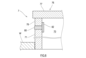
- FIG. 6 is a partial sectional view of a manhole structure showing a third example of a joint structure between a manhole body and a manhole cover.
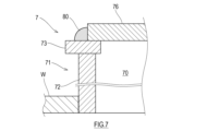
- FIG. 7 is a partial sectional view of a manhole structure showing Example 4 of a joint structure between a manhole body and a manhole cover.
- FIG. 8 is a partial sectional view of a manhole structure showing Example 5 of a joint structure between a manhole body and a manhole cover.
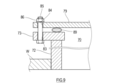
- FIG. 9 is a partial sectional view of a manhole structure showing Example 5 of a joint structure between a manhole body and a manhole cover.
- FIG. 10 is a partial sectional view of a manhole structure showing Example 6 of a joint structure between a manhole body and a manhole cover.
- FIG. 11 is a diagram showing an example of a multi-shell tank in which a manhole structure is arranged on the wall of the inner tank.
- FIG. 12 is a diagram illustrating an example of a multi-shell tank in which a manhole structure is placed on the wall of the tank dome.
- FIG. 1 is a schematic configuration diagram of a ship 1 equipped with a multi-shell tank 3 according to an embodiment of the present disclosure.
- a ship 1 shown in FIG. 1 includes a hull 2 and four multi-shell tanks 3 mounted on the hull 2.
- the multi-shell tank 3 according to this embodiment is a cargo tank for transporting liquefied hydrogen, and the ship 1 is a liquefied hydrogen carrier.
- the type of liquefied gas contained in the multi-shell tank 3 is not limited to liquefied hydrogen.
- the hull 2 has a plurality of holds 21.
- the plurality of holds 21 are lined up in the longitudinal direction, and the holds 21 are partitioned from each other by partition walls 22.
- the lower part of the multi-shell tank 3 is housed inside each hold 21.
- the upper part of the multi-shell tank 3 is covered with a tank cover 6.
- the multi-shell tank 3 is surrounded by a bulkhead 22, which is a component of the hull 2 forming a hold 21, and a tank cover 6.
- the multi-shell tanks 3 are lined up in the ship's ship direction, but if the ship width is wide, they may be lined up in the ship width direction. Further, the number of multi-shell tanks 3 mounted on the hull 2 may be one, or two or more.
- FIG. 2 is a sectional view in the width direction of the ship 1 showing a cross section of the multi-shell tank 3 according to the embodiment.
- the multi-shell tank 3 is a spherical tank of an independent support tank type independent from the hull 2.
- the multi-shell tank 3 is not limited to the independent support tank type.
- the multi-shell tank 3 is not limited to a spherical tank, but may also be a deformed spherical tank with an oblong ellipsoid shape, a stretch tank with hemispherical top and bottom sides and a cylindrical part in between, or a square tank with a rectangular parallelepiped shape. good.
- the multi-shell tank 3 includes an inner tank 4 that contains liquefied gas, and an outer tank 5 that surrounds the inner tank 4.
- the inner tank 4 and the outer tank 5 are supported by the hull 2 via a skirt 25.
- the multi-shell tank 3 according to the present embodiment is a double-shell tank including one inner tank 4 and one outer tank 5, but there is at least one intermediate tank between the inner tank 4 and the outer tank 5. It may be a tank with three or more tanks arranged.
- the inner tank 4 includes an inner tank body 41 that accommodates liquefied gas.
- the inner tank 4 may be provided with an inner tank dome that projects upward from the inner tank main body 41.
- the outer tank 5 includes an outer tank main body 51 surrounding the inner tank main body 41.
- the outer tank 5 may be provided with an outer tank dome that projects upward from the outer tank main body 51.
- the inner tank 4 and the outer tank 5 are spaced apart in the thickness direction of the tank.
- the space between the inner tank 4 and the outer tank 5 is referred to as "inner and outer tank space 31."
- a heat insulating layer is formed between the inner and outer tanks 31 by a cold insulation gas filled in the inner and outer tanks 31 and a heat insulating material.
- the space between the inner and outer tanks 31 is substantially at atmospheric pressure or a low vacuum state.
- the cold preservation gas is hydrogen gas or helium gas.
- Atmospheric pressure refers to approximately 10 5 Pa, but since the pressure between the inner and outer tanks 31 may fluctuate depending on the temperature, movement of the hull 2, etc., "substantially atmospheric pressure" is approximately 10 5 Pa, and approximately Atmospheric pressures higher than 10 5 Pa may be included in the range of pressure fluctuations. Moreover, a low vacuum state is a pressure lower than atmospheric pressure, and refers to an air pressure between 10 5 Pa and 10 2 Pa.
- the cold storage gas is hydrogen gas, even if the gas phase part of the inner tank 4 and the space between the inner and outer tanks 31 are communicated so that the vaporized gas generated in the inner tank 4 flows into the space between the inner and outer tanks 31. good.
- a heat insulating layer is placed between the inner and outer tanks 31 and the space between the inner and outer tanks 31 is made vacuum, so that there is a gap between the inner tank 4 and the outer tank 5.
- a vacuum insulation layer may be provided.
- a pipe tower 8 extending vertically is provided approximately at the center of the multi-shell tank 3.
- a tank dome 88 is arranged at the top of the pipe tower 8.
- Tank dome 88 penetrates inner tank 4 and outer tank 5.
- the top of the tank dome 88 is located above the tank cover 6. Pipes, wiring, etc. passed through the pipe tower 8 are drawn out through a tank dome 88.
- the outer tank 5 is provided with a manhole structure 7 that forms a manhole 70 for workers and the like to access the space between the inner and outer tanks 31.
- the manhole 70 of the outer tank 5 is used, for example, for maintenance and inspection of the space between the inner and outer tanks 31.
- the manhole structure 7 is provided only in the outer tank 5, but as shown in FIG. 7 may be arranged, or the manhole structure 7 may be arranged on the wall W of the tank dome 88 of the multi-shell tank 3 as shown in FIG.
- the manhole structure 7 is arranged at the top of the outer tank 5, but the manhole structure 7 may be arranged at the bottom or side of the outer tank 5. .
- the manhole structure 7 includes a manhole body 71 that forms the manhole 70, a manhole cover 76 that closes the manhole 70, and a fusion joint 80 that joins the manhole body 71 and the manhole cover 76. That is, the manhole body 71 and the manhole cover 76 are joined by welding.
- FIG. 3 is a cross-sectional view of the manhole structure 7.
- the manhole body 71 has a cylindrical shape that penetrates the wall W of the outer tank 5, is joined to the wall W, and projects outward from the wall W.
- the manhole body 71 may protrude inward from the wall W of the outer tank 5, that is, into the space 31 between the inner and outer tanks.
- the inside of the manhole body 71 is a space communicating with the inner and outer tank space 31, and the manhole body 71 forms the manhole 70.
- the manhole structure 7 illustrated in FIG. 2 forms a manhole 70 that communicates between the inner and outer tanks 31 and the outside of the tank cover 6.
- the manhole body 71 penetrates the outer tank body 51 and the tank cover 6, and the manhole body 71 extends through the outer tank body 51 and the tank cover 6. 71 is joined to the outer tank main body 51 and the tank cover 6.
- the installation mode of the manhole structure 7 joined to the wall W of the outer tank 5 is not limited to this.
- the manhole structure 7 forms a manhole 70 that communicates between the inner and outer tanks 31 and between the tank cover 6 and the outer tank 5, and the manhole cover 76 is disposed between the tank cover 6 and the outer tank 5.
- the manhole body 71 may be joined only to the wall W of the outer tank 5.
- the manhole body 71 forms a manhole 70 that communicates the inside of the inner tank 4 with the outside of the tank cover 6, and the manhole body 71 connects the inner tank 4, the outer tank 5, and the tank cover. 6, the manhole body 71 is joined to each wall W of the inner tank 4, outer tank 5, and tank cover 6.
- the installation mode of the manhole structure 7 joined to the wall W of the inner tank 4 is not limited to this.
- the manhole structure 7 forms a manhole 70 that communicates between the inside of the inner tank 4 and the space between the inner and outer tanks 31, the manhole cover 76 is disposed between the inner and outer tanks 31, and the manhole body 71 is arranged between the inner and outer tanks 4. It may be joined only to the wall W.
- the manhole structure 7 forms a manhole 70 that communicates between the inside of the inner tank 4, the outer tank 5, and the tank cover 6, and the manhole cover 76 connects between the outer tank 5 and the tank cover 6.
- the manhole body 71 may be connected to the walls W of the inner tank 4 and the outer tank 5.
- the manhole body 71 and the manhole cover 76 are joined by welding.
- a fusion joint 80 is arranged at the joint between the manhole body 71 and the manhole cover 76.
- the fused joint portion 80 may be formed by melting the base material and filler metal during welding of the manhole body 71 and the manhole cover 76 and then cooling them.
- the fused joint portion 80 may be formed by melting the base materials of the manhole body 71 and the manhole cover 76 during welding and then cooling.
- FIG. 4 is a partial cross-sectional view of the manhole structure 7 showing an example 1 of the joint structure between the manhole body 71 and the manhole cover 76.
- the outer diameter of the manhole cover 76 is larger than the outer diameter of the manhole body 71.
- the lower surface of the manhole cover 76 and the end surface of the manhole body 71 are welded together in a butted state.
- the melted joint 80 in this case is arranged between the end surface of the manhole body 71 and the surface of the manhole cover 76.
- FIG. 5 is a partial cross-sectional view of the manhole structure 7 showing a second example of the joint structure between the manhole body 71 and the manhole cover 76.
- the outer diameter of the manhole cover 76 is slightly smaller than the inner diameter of the manhole body 71.
- the outer circumferential surface (that is, the side surface) of the manhole cover 76 and the inner circumferential surface of the manhole body 71 are butted and welded together.
- the melted joint portion 80 in this case is arranged between the inner circumferential surface of the manhole body 71 and the outer circumferential surface of the manhole cover 76.
- FIG. 6 is a partial cross-sectional view of the manhole structure 7 showing a third example of a joint structure between the manhole body 71 and the manhole cover 76.
- the manhole cover 76 includes a cover plate 77 and a connecting ring 78 that projects from the cover plate 77 toward the manhole body 71.
- the connecting ring 78 is a short cylindrical body having substantially the same diameter as the manhole body 71.
- the cover plate 77 and the connection ring 78 may be integral, or the cover plate 77 and the connection ring 78 may be integrally joined by welding in an airtight manner.
- connection ring 78 and the end surface of the manhole body 71 are welded together in a butted state.
- the fused joint 80 in this case is arranged between the manhole body 71 and the connecting ring 78.
- the manhole cover 76 having the connection ring 78 as shown in FIG. 6, after the manhole body 71 and the manhole cover 76 are joined by welding, when the manhole 70 is opened, the fused joint 80 or the connection ring 78 is used to form the manhole structure. By cutting the body 7, the manhole cover 76 can be removed from the manhole body 71. In this way, the manhole cover 76 can be used repeatedly by defining the connection ring 78 as the cutting point, designing the connection ring 78 to be long in advance, and cutting off the connection ring 78 from the bottom each time it is cut. be.
- a backing ring 82 ie, a backing metal
- the backing ring 82 used during welding may remain in the multi-shell tank 3 after welding.
- the backing ring 82 remaining in the multi-shell tank 3 is placed within the manhole 70 along the fused joint 80.
- FIG. 7 is a partial cross-sectional view of the manhole structure 7 showing a fourth example of the joining structure between the manhole body 71 and the manhole cover 76.
- the manhole body 71 includes a body tube 72 and an annular plate 73 disposed at an end of the body tube 72.
- the barrel tube 72 is the main body portion of the manhole barrel 71 and has a cylindrical shape.
- the annular plate 73 is an annular plate member coupled to the end of the barrel tube 72 .
- the inner peripheral surface of the annular plate 73 and the outer peripheral surface of the barrel tube 72 may be joined like a conventional flange.
- the barrel tube 72 and the annular plate 73 are integrated by welding, the barrel tube 72 and the annular plate 73 may be an integral body formed by machining or casting.
- the annular plate 73 projects like a flange toward the outer circumference of the manhole body 71.
- the annular plate 73 may also protrude toward the inner peripheral side of the manhole body 71.
- the lower surface of the annular plate 73 and the end surface of the barrel tube 72 are butted and joined.
- the peripheral edge of the manhole cover 76 placed on the annular plate 73 and the lower surface of the manhole cover 76 and the upper surface of the annular plate 73 contacting each other, the surface of the annular plate 73 and the end surface of the manhole cover 76 are in contact with each other.
- the melted joint 80 in this case is arranged between the end surface of the manhole cover 76 and the surface of the annular plate 73.
- FIG. 8 is a partial cross-sectional view of the manhole structure 7 showing a fifth example of the joining structure between the manhole body 71 and the manhole cover 76.
- the manhole body 71 includes a body tube 72 and an annular plate 73 coupled to the body tube 72.
- the manhole cover 76 also includes a cover plate 77 and a connecting ring 78 coupled to the cover plate 77.
- the description of Example 3 is cited by reference.
- the lower surface of the annular plate 73 and the end surface of the barrel tube 72 are butted and joined.
- the end face of the connecting ring 78 of the manhole cover 76 and the upper surface of the annular plate 73 of the manhole body 71 are welded together in a butted state.
- the fused joint 80 in this case is arranged between the connecting ring 78 and the annular plate 73.
- the manhole body 71 and the manhole cover 76 are welded by complete penetration.
- a backing ring 82 ie, a backing metal
- the backing ring 82 used during welding may remain in the multi-shell tank 3 after welding.
- the backing ring 82 remaining in the multi-shell tank 3 is placed within the manhole 70 along the fused joint 80.
- the annular plate 73 of the manhole body 71 may be expanded further toward the outer circumference and bolt holes may be provided there.
- bolt holes 83 are arranged in a portion of the annular plate 73 of the manhole body 71 that expands toward the outer circumference.
- FIG. 10 is a partial cross-sectional view of the manhole structure 7 showing a sixth example of the joining structure between the manhole body 71 and the manhole cover 76.
- an inner cover 61 is added to the manhole structure 7 according to Example 1.
- the inner cover 61 is applicable not only to the manhole structure 7 according to Example 1 but also to the manhole structures 7 according to Examples 2 to 5.
- Example 1 For the specific structures of the manhole body 71 and manhole cover 76 of the manhole structure 7, the description of Example 1 is cited by reference.
- An inner cover receiver 63 that protrudes inward from the inner wall of the manhole shell 71 is fixed to the inner periphery of the manhole shell 71.
- the inner lid receiver 63 is arranged below the melted joint part 80.
- the inner cover receiver 63 may be a continuous annular member along the inner circumference of the manhole shell 71 or may be a plurality of plate-like members arranged along the inner circumference of the manhole shell 71.
- the inner cover 61 is a circular plate that is one size smaller than the inner circumference of the manhole structure 7.
- the inner cover 61 may be of any type as long as it can mainly close the peripheral portion, and an opening through which the pipe can pass may be provided in the center of the inner cover 61.
- a peripheral portion of the inner lid 61 is placed on the inner lid holder 63.
- the inner lid 61 is removably fixed to the inner lid receiver 63 by a fastener 62.
- the inner cover 61 is placed on the inner cover receiver 63, and the inner cover 61 is fixed to the inner cover receiver 63 with the fasteners 62.
- the manhole cover 76 is placed on the manhole body 71, and the manhole body 71 and the manhole cover 76 are fixed by welding. Sparks may be generated when welding the manhole body 71 and the manhole cover 76, but since the sparks are caught by the inner cover 61, the sparks can be prevented from passing through the manhole 70 and falling downward.
- the manhole structure 7 according to Example 6 when opening the sealed manhole 70, a part of the manhole structure 7 is first cut.
- sparks and chips may be generated during cutting, but since these sparks and chips are caught by the inner cover 61, it is possible to prevent the sparks and chips from passing through the manhole 70 and falling downward.
- the fastening between the inner cover receiver 63 and the inner cover 61 by the fastener 62 is released, and the inner cover 61 is taken out from inside the manhole body 71. This opens the manhole 70.
- the inner cover 61 can prevent sparks and chips from falling into the inner tank 4. Further, when the manhole structure 7 is arranged on the wall W of the outer tank 5, the inner cover 61 can prevent sparks and chips from falling into the gap 31 between the inner and outer tanks. When the manhole structure 7 is arranged in the tank dome 88, the inner cover 61 can prevent sparks and chips from falling into the tank dome 88.
- the manhole structure 7 is a manhole structure 7 disposed on the wall of a tank 3 containing liquefied gas, and includes: A cylindrical manhole body 71 that is joined to the wall W and protrudes inwardly or outwardly from the wall W, a manhole cover 76 that closes the manhole 70 formed by the manhole body 71, and the manhole body 71 and the manhole cover 76 are joined. It is characterized in that it includes a fused joint part 80.
- the manhole body 71 and the manhole cover 76 can be airtightly sealed, compared to the case where the manhole body 71 and the manhole cover 76 are fastened with bolts and nuts via a gasket seal. It can be sealed with Therefore, gas flow between the manhole body 71 and the manhole cover 76 is prevented.
- a tank 3 including an inner tank 4 and an outer tank 5 surrounding the inner tank 4 when the manhole structure 7 is arranged on the wall W of the outer tank 5, the inner tank 4 and the outer tank 5 are It is possible to prevent gas from leaking between the inner and outer tanks 31 and to maintain the degree of vacuum between the inner and outer tanks 31.
- a tank 3 including an inner tank 4 and an outer tank 5 surrounding the inner tank 4 when the manhole structure 7 is arranged on the wall W of the inner tank 4, leakage of gas from the inner tank 4 is prevented.
- the degree of vacuum in the inner tank 4 can be maintained.
- a manhole structure 7 according to a second item of the present disclosure is the manhole structure 7 according to the first item further including a backing ring 82 disposed inside the manhole 70 along the fusion joint 80. be.
- manhole body 71 and the manhole cover 76 be completely penetrated and welded.
- manhole structure 7 when welding the manhole body 71 and the manhole cover 76 by complete penetration, welding can be performed while backing them with the backing ring 82. Therefore, it is sufficient to weld from one side of the outside of the manhole body 71, and in addition, welding defects are reduced. Note that since the manhole structure 7 is normally placed in a place where it is not directly exposed to the liquefied gas contained in the inner tank 4, even if the backing ring 82 remains in the manhole structure 7, the backing ring 82 does not impair the performance of tank 3.
- the manhole structure 7 according to the third item of the present disclosure is the manhole structure 7 according to the first or second item, in which the manhole cover 76 includes a cover plate 77 and a manhole cover 76 that protrudes from the cover plate 77 toward the manhole body 71.
- the connecting ring 78 is joined to the manhole body 71 via a fusion joint 80.
- a manhole structure 7 according to a fourth item of the present disclosure is a manhole structure 7 according to any one of the first to third items, in which a manhole body 71 is arranged in a body tube 72 and at an end of the body tube 72.
- the annular plate 73 is joined to a manhole cover 76 via a fusion joint 80.
- the connecting ring 78 can be placed on the annular plate 73 and welded together, and the welded location can be stably maintained in position during the welding operation. Further, welding work can be performed using the annular plate 73 as a foothold, and welding work can be performed in a stable posture.
- a manhole structure 7 according to a fifth item of the present disclosure is a manhole structure 7 according to any one of the first to fourth items, in which an inner cover 61 is disposed below a melt joint 80 in a manhole body 71. It further comprises:
- the multi-shell tank 3 includes: an inner tank 4 containing liquefied gas; an outer tank 5 surrounding the inner tank 4;
- the manhole structure 7 according to any one of the first to fifth items is arranged on the wall W of the inner tank 4 or the outer tank 5.
- the multi-shell tank 3 includes: an inner tank 4 containing liquefied gas; an outer tank 5 surrounding the inner tank 4; a tank dome 88 that penetrates the inner tank 4 and the outer tank 5 and projects upward;
- the manhole structure 7 according to any one of the first to fifth items is arranged on the wall W of at least one of the inner tank 4, the outer tank 5, and the tank dome 88.
- the manhole structure 7 having the above configuration has high airtightness, it is suitable as the manhole structure 7 disposed to form the manhole 70 on the wall W of the multi-shell tank 3 containing liquefied gas.
- a ship 1 according to the eighth item of the present disclosure includes a hull 2 and a multi-shell tank 3 according to the sixth or seventh item mounted on the hull 2.
- the manhole cover 76 of the manhole structure 7 is fixed to the manhole body 71 by welding, so that the connection between the manhole cover 76 and the manhole body 71 may loosen due to movement of the ship 1 or the like. Gas does not flow between the manhole cover 76 and the manhole body 71. Therefore, the multi-shell tank 3 described above is suitable as a cargo tank mounted on the ship 1, although it can also be placed on land.
- the multi-shell tank 3 is mounted on the ship 1, but the structure of the multi-shell tank 3 of the present disclosure can also be applied to a multi-shell tank installed on land. Further, the structure of the manhole structure 7 of the multi-shell tank 3 of the present disclosure can be applied to openings other than the manholes formed in the inner tank 4 and outer tank 5 of the multi-shell tank 3 that are required to be opened and closed.
Landscapes
- Engineering & Computer Science (AREA)
- Mechanical Engineering (AREA)
- Chemical & Material Sciences (AREA)
- Combustion & Propulsion (AREA)
- Ocean & Marine Engineering (AREA)
- General Engineering & Computer Science (AREA)
- Physics & Mathematics (AREA)
- Thermal Sciences (AREA)
- Filling Or Discharging Of Gas Storage Vessels (AREA)
Priority Applications (3)
| Application Number | Priority Date | Filing Date | Title |
|---|---|---|---|
| JP2024523343A JP7828445B2 (ja) | 2022-05-27 | 2023-05-25 | マンホール構造体、多重殻タンク及び船舶 |
| CN202380033729.6A CN119032053A (zh) | 2022-05-27 | 2023-05-25 | 检修孔构造体、多层壳罐以及船舶 |
| KR1020247038991A KR20250004857A (ko) | 2022-05-27 | 2023-05-25 | 맨홀 구조체, 다중각 탱크 및 선박 |
Applications Claiming Priority (2)
| Application Number | Priority Date | Filing Date | Title |
|---|---|---|---|
| JP2022-087143 | 2022-05-27 | ||
| JP2022087143 | 2022-05-27 |
Publications (1)
| Publication Number | Publication Date |
|---|---|
| WO2023229008A1 true WO2023229008A1 (ja) | 2023-11-30 |
Family
ID=88919455
Family Applications (1)
| Application Number | Title | Priority Date | Filing Date |
|---|---|---|---|
| PCT/JP2023/019505 Ceased WO2023229008A1 (ja) | 2022-05-27 | 2023-05-25 | マンホール構造体、多重殻タンク及び船舶 |
Country Status (4)
| Country | Link |
|---|---|
| JP (1) | JP7828445B2 (https=) |
| KR (1) | KR20250004857A (https=) |
| CN (1) | CN119032053A (https=) |
| WO (1) | WO2023229008A1 (https=) |
Cited By (1)
| Publication number | Priority date | Publication date | Assignee | Title |
|---|---|---|---|---|
| KR102864197B1 (ko) * | 2024-11-21 | 2025-09-25 | 주식회사 하이솔 | 액화가스 저장탱크의 단열재 충전 방법 |
Citations (8)
| Publication number | Priority date | Publication date | Assignee | Title |
|---|---|---|---|---|
| JPS51128653A (en) * | 1975-05-02 | 1976-11-09 | Nippon Kokan Kk | Method of joinning steel pipes |
| JPS57142888A (en) * | 1981-02-16 | 1982-09-03 | Kawasaki Heavy Ind Ltd | Method of opening manhole for tank |
| JP2003095382A (ja) * | 2001-09-25 | 2003-04-03 | Ishikawajima Harima Heavy Ind Co Ltd | タンクのマンホール構造 |
| JP2005537995A (ja) * | 2002-09-06 | 2005-12-15 | フェガ グリースハーベル コマンディトゲゼルシャフト | 容器蓋またはフランジ蓋 |
| JP2011000901A (ja) * | 2009-06-16 | 2011-01-06 | Ihi Marine United Inc | 液化ガスタンクのドーム構造 |
| JP2011084316A (ja) * | 2009-10-16 | 2011-04-28 | Ihi Corp | タンクのマンホール構造体 |
| WO2014097974A1 (ja) * | 2012-12-19 | 2014-06-26 | 川崎重工業株式会社 | 液化ガス用輸送容器 |
| JP2020015535A (ja) * | 2018-07-27 | 2020-01-30 | 川崎重工業株式会社 | 二重殻タンク |
-
2023
- 2023-05-25 WO PCT/JP2023/019505 patent/WO2023229008A1/ja not_active Ceased
- 2023-05-25 CN CN202380033729.6A patent/CN119032053A/zh active Pending
- 2023-05-25 KR KR1020247038991A patent/KR20250004857A/ko active Pending
- 2023-05-25 JP JP2024523343A patent/JP7828445B2/ja active Active
Patent Citations (8)
| Publication number | Priority date | Publication date | Assignee | Title |
|---|---|---|---|---|
| JPS51128653A (en) * | 1975-05-02 | 1976-11-09 | Nippon Kokan Kk | Method of joinning steel pipes |
| JPS57142888A (en) * | 1981-02-16 | 1982-09-03 | Kawasaki Heavy Ind Ltd | Method of opening manhole for tank |
| JP2003095382A (ja) * | 2001-09-25 | 2003-04-03 | Ishikawajima Harima Heavy Ind Co Ltd | タンクのマンホール構造 |
| JP2005537995A (ja) * | 2002-09-06 | 2005-12-15 | フェガ グリースハーベル コマンディトゲゼルシャフト | 容器蓋またはフランジ蓋 |
| JP2011000901A (ja) * | 2009-06-16 | 2011-01-06 | Ihi Marine United Inc | 液化ガスタンクのドーム構造 |
| JP2011084316A (ja) * | 2009-10-16 | 2011-04-28 | Ihi Corp | タンクのマンホール構造体 |
| WO2014097974A1 (ja) * | 2012-12-19 | 2014-06-26 | 川崎重工業株式会社 | 液化ガス用輸送容器 |
| JP2020015535A (ja) * | 2018-07-27 | 2020-01-30 | 川崎重工業株式会社 | 二重殻タンク |
Cited By (1)
| Publication number | Priority date | Publication date | Assignee | Title |
|---|---|---|---|---|
| KR102864197B1 (ko) * | 2024-11-21 | 2025-09-25 | 주식회사 하이솔 | 액화가스 저장탱크의 단열재 충전 방법 |
Also Published As
| Publication number | Publication date |
|---|---|
| CN119032053A (zh) | 2024-11-26 |
| JPWO2023229008A1 (https=) | 2023-11-30 |
| KR20250004857A (ko) | 2025-01-08 |
| JP7828445B2 (ja) | 2026-03-11 |
Similar Documents
| Publication | Publication Date | Title |
|---|---|---|
| KR20140105023A (ko) | 파이프를 포함하는 용기 벽 | |
| EP2682337B1 (en) | Tank dome flange portion structure | |
| CA2954939C (en) | Anchor structure, and liquefied natural gas storage tank comprising said anchor structure | |
| KR20190020317A (ko) | 밀폐 단열 베슬을 위한 가스 돔 구조물 | |
| WO2023229008A1 (ja) | マンホール構造体、多重殻タンク及び船舶 | |
| CN118270179B (zh) | 用于船用装备的集成式安装结构和具有其的储存容器 | |
| KR100649316B1 (ko) | 액화천연가스 저장탱크의 앵커 구조체 | |
| KR20230009428A (ko) | 추가적인 해치가 갖추어진 개구를 구비하는, 액화 가스를 위한 저장 탱크의 리퀴드 돔 | |
| CN220061423U (zh) | 一种船运co2液货罐的气室结构 | |
| KR20220149441A (ko) | 액화가스 저장장치 | |
| JP2022171607A5 (https=) | ||
| EP3760910B1 (en) | Double-shell tank and liquefied gas carrier ship | |
| KR101610255B1 (ko) | 앵커 구조체, 앵커 구조체를 포함하는 액화천연가스 저장탱크 및 액화천연가스 저장탱크 제조 방법 | |
| KR20210134978A (ko) | 부싱 주위의 개선된 단열을 포함하는 용기 벽 | |
| CN218268525U (zh) | 一种液氢储罐 | |
| KR102304651B1 (ko) | 선박용 액화가스 저장탱크 | |
| KR101843863B1 (ko) | 독립형 저장탱크의 단열구조체 및 그 단열구조체의 제작방법 | |
| KR20200080589A (ko) | 액화천연가스 저장탱크의 단열벽 고정장치 | |
| KR20200095624A (ko) | 누출 방지 장치를 포함하는 극저온 저장탱크의 가스 돔 구조 | |
| KR102717641B1 (ko) | 앵커 구조체 | |
| KR102742192B1 (ko) | 가압형 극저온 저장탱크의 패싱 홀 구조 | |
| KR102754067B1 (ko) | 액화천연가스 저장탱크의 단열벽 고정장치 | |
| JP2024101139A (ja) | 高圧ガス貯留装置 | |
| KR20210088833A (ko) | 액화가스 저장탱크 및 액화가스 저장탱크의 제작 방법 | |
| RU2794401C1 (ru) | Хранилище сжиженного газа, судно, включающее хранилище, система перекачки холодного жидкого продукта на судне и способ погрузки или разгрузки судна |
Legal Events
| Date | Code | Title | Description |
|---|---|---|---|
| 121 | Ep: the epo has been informed by wipo that ep was designated in this application |
Ref document number: 23811880 Country of ref document: EP Kind code of ref document: A1 |
|
| ENP | Entry into the national phase |
Ref document number: 2024523343 Country of ref document: JP Kind code of ref document: A |
|
| WWE | Wipo information: entry into national phase |
Ref document number: 202380033729.6 Country of ref document: CN |
|
| ENP | Entry into the national phase |
Ref document number: 20247038991 Country of ref document: KR Kind code of ref document: A |
|
| WWE | Wipo information: entry into national phase |
Ref document number: 1020247038991 Country of ref document: KR |
|
| NENP | Non-entry into the national phase |
Ref country code: DE |
|
| 122 | Ep: pct application non-entry in european phase |
Ref document number: 23811880 Country of ref document: EP Kind code of ref document: A1 |