WO2023228903A1 - 液晶ポリマーパウダー、液晶ポリマーフィルム、および、それらの製造方法 - Google Patents
液晶ポリマーパウダー、液晶ポリマーフィルム、および、それらの製造方法 Download PDFInfo
- Publication number
- WO2023228903A1 WO2023228903A1 PCT/JP2023/018959 JP2023018959W WO2023228903A1 WO 2023228903 A1 WO2023228903 A1 WO 2023228903A1 JP 2023018959 W JP2023018959 W JP 2023018959W WO 2023228903 A1 WO2023228903 A1 WO 2023228903A1
- Authority
- WO
- WIPO (PCT)
- Prior art keywords
- liquid crystal
- crystal polymer
- polymer powder
- fiber mat
- powder
- Prior art date
- Legal status (The legal status is an assumption and is not a legal conclusion. Google has not performed a legal analysis and makes no representation as to the accuracy of the status listed.)
- Ceased
Links
Images



Classifications
-
- D—TEXTILES; PAPER
- D21—PAPER-MAKING; PRODUCTION OF CELLULOSE
- D21H—PULP COMPOSITIONS; PREPARATION THEREOF NOT COVERED BY SUBCLASSES D21C OR D21D; IMPREGNATING OR COATING OF PAPER; TREATMENT OF FINISHED PAPER NOT COVERED BY CLASS B31 OR SUBCLASS D21G; PAPER NOT OTHERWISE PROVIDED FOR
- D21H13/00—Pulp or paper, comprising synthetic cellulose or non-cellulose fibres or web-forming material
- D21H13/10—Organic non-cellulose fibres
- D21H13/20—Organic non-cellulose fibres from macromolecular compounds obtained otherwise than by reactions only involving carbon-to-carbon unsaturated bonds
- D21H13/24—Polyesters
-
- B—PERFORMING OPERATIONS; TRANSPORTING
- B32—LAYERED PRODUCTS
- B32B—LAYERED PRODUCTS, i.e. PRODUCTS BUILT-UP OF STRATA OF FLAT OR NON-FLAT, e.g. CELLULAR OR HONEYCOMB, FORM
- B32B15/00—Layered products comprising a layer of metal
- B32B15/04—Layered products comprising a layer of metal comprising metal as the main or only constituent of a layer, which is next to another layer of the same or of a different material
- B32B15/08—Layered products comprising a layer of metal comprising metal as the main or only constituent of a layer, which is next to another layer of the same or of a different material of synthetic resin
-
- C—CHEMISTRY; METALLURGY
- C08—ORGANIC MACROMOLECULAR COMPOUNDS; THEIR PREPARATION OR CHEMICAL WORKING-UP; COMPOSITIONS BASED THEREON
- C08G—MACROMOLECULAR COMPOUNDS OBTAINED OTHERWISE THAN BY REACTIONS ONLY INVOLVING UNSATURATED CARBON-TO-CARBON BONDS
- C08G63/00—Macromolecular compounds obtained by reactions forming a carboxylic ester link in the main chain of the macromolecule
- C08G63/02—Polyesters derived from hydroxycarboxylic acids or from polycarboxylic acids and polyhydroxy compounds
- C08G63/06—Polyesters derived from hydroxycarboxylic acids or from polycarboxylic acids and polyhydroxy compounds derived from hydroxycarboxylic acids
- C08G63/065—Polyesters derived from hydroxycarboxylic acids or from polycarboxylic acids and polyhydroxy compounds derived from hydroxycarboxylic acids the hydroxy and carboxylic ester groups being bound to aromatic rings
-
- C—CHEMISTRY; METALLURGY
- C08—ORGANIC MACROMOLECULAR COMPOUNDS; THEIR PREPARATION OR CHEMICAL WORKING-UP; COMPOSITIONS BASED THEREON
- C08J—WORKING-UP; GENERAL PROCESSES OF COMPOUNDING; AFTER-TREATMENT NOT COVERED BY SUBCLASSES C08B, C08C, C08F, C08G or C08H
- C08J3/00—Processes of treating or compounding macromolecular substances
- C08J3/02—Making solutions, dispersions, lattices or gels by other methods than by solution, emulsion or suspension polymerisation techniques
- C08J3/03—Making solutions, dispersions, lattices or gels by other methods than by solution, emulsion or suspension polymerisation techniques in aqueous media
-
- C—CHEMISTRY; METALLURGY
- C08—ORGANIC MACROMOLECULAR COMPOUNDS; THEIR PREPARATION OR CHEMICAL WORKING-UP; COMPOSITIONS BASED THEREON
- C08J—WORKING-UP; GENERAL PROCESSES OF COMPOUNDING; AFTER-TREATMENT NOT COVERED BY SUBCLASSES C08B, C08C, C08F, C08G or C08H
- C08J3/00—Processes of treating or compounding macromolecular substances
- C08J3/12—Powdering or granulating
-
- C—CHEMISTRY; METALLURGY
- C08—ORGANIC MACROMOLECULAR COMPOUNDS; THEIR PREPARATION OR CHEMICAL WORKING-UP; COMPOSITIONS BASED THEREON
- C08J—WORKING-UP; GENERAL PROCESSES OF COMPOUNDING; AFTER-TREATMENT NOT COVERED BY SUBCLASSES C08B, C08C, C08F, C08G or C08H
- C08J5/00—Manufacture of articles or shaped materials containing macromolecular substances
- C08J5/18—Manufacture of films or sheets
-
- D—TEXTILES; PAPER
- D21—PAPER-MAKING; PRODUCTION OF CELLULOSE
- D21D—TREATMENT OF THE MATERIALS BEFORE PASSING TO THE PAPER-MAKING MACHINE
- D21D1/00—Methods of beating or refining; Beaters of the Hollander type
- D21D1/20—Methods of refining
-
- D—TEXTILES; PAPER
- D21—PAPER-MAKING; PRODUCTION OF CELLULOSE
- D21H—PULP COMPOSITIONS; PREPARATION THEREOF NOT COVERED BY SUBCLASSES D21C OR D21D; IMPREGNATING OR COATING OF PAPER; TREATMENT OF FINISHED PAPER NOT COVERED BY CLASS B31 OR SUBCLASS D21G; PAPER NOT OTHERWISE PROVIDED FOR
- D21H25/00—After-treatment of paper not provided for in groups D21H17/00 - D21H23/00
- D21H25/04—Physical treatment, e.g. heating, irradiating
-
- C—CHEMISTRY; METALLURGY
- C08—ORGANIC MACROMOLECULAR COMPOUNDS; THEIR PREPARATION OR CHEMICAL WORKING-UP; COMPOSITIONS BASED THEREON
- C08G—MACROMOLECULAR COMPOUNDS OBTAINED OTHERWISE THAN BY REACTIONS ONLY INVOLVING UNSATURATED CARBON-TO-CARBON BONDS
- C08G2250/00—Compositions for preparing crystalline polymers
Definitions
- the present invention relates to a liquid crystal polymer powder, a method for manufacturing a liquid crystal polymer powder, a liquid crystal polymer film, and a method for manufacturing a liquid crystal polymer film.
- liquid crystal polymer a material with lower transmission loss and excellent high frequency characteristics than conventional materials, has been attracting attention as a new substrate material for printed wiring compatible with next-generation high-speed transmission.
- LCP liquid crystal polymer
- polyimide resin which is a conventional substrate material
- LCP has excellent low dielectric constant properties, high heat resistance, and low water absorption, so it can reduce loss of electrical signals and the like.
- melt extrusion methods and solution casting methods are known as methods for producing LCP films used for printed wiring boards and the like from liquid crystal polymers.
- the melt extrusion method is a method of forming a film by extruding a molten resin from a device and bringing it into contact with a roll.
- the solution casting method is a method of forming an LCP film by applying a varnish made by dissolving an LCP raw material such as LCP pellets in a solvent onto a flat belt and drying it.
- Patent Document 1 describes a method for producing fibrillar liquid crystal polymer powder.
- a liquid crystal polymer (LCP) powder is first obtained by crushing a biaxially oriented film of liquid crystal polymer.
- the obtained LCP powder is processed using a wet high-pressure crusher to produce fibrillar LCP powder.
- An LCP film can also be produced using such fibrillar LCP powder as a raw material.
- the bending strength of the LCP film is improved by improving the bondability between fibrillar LCP particles after drying.
- Patent Document 2 Japanese Unexamined Patent Publication No. 5-125160 discloses a resin composition exhibiting liquid crystallinity composed of two types of segments, and the resin composition has a small temperature dependence of melt viscosity characteristics. , it is described that the resin has excellent moldability and that molded products of good shape (sheets with uniform thickness) can be obtained using the resin. Patent Document 2 describes that the resin composition has a melt viscosity of 800 poise (80 Pa ⁇ s) or more at a temperature of 245° C. and a shear rate of 1000 per second (sec ⁇ 1 ).
- Patent No. 5904307 Japanese Patent Application Publication No. 5-125160
- the liquid crystal polymer film has high bending strength in order to improve the reliability of the printed wiring when it is used, for example, as a substrate for printed wiring.
- high bending strength is required.
- conventional liquid crystal polymer films have room for further improvement in folding strength.
- the present invention aims to obtain a liquid crystal polymer film with improved bending strength.
- the liquid crystal polymer powder according to the first aspect of the present invention includes fibrous particles made of a liquid crystal polymer.
- the melt viscosity of the liquid crystal polymer powder is 15 to 77 Pa ⁇ s.
- the liquid crystal polymer film based on the second aspect of the present invention includes a liquid crystal polymer.
- the MIT folding resistance of the liquid crystal polymer film is 100 times or more.
- the folding strength of a liquid crystal polymer film can be improved.
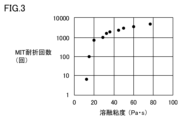
- FIG. 3 is a diagram showing the relationship between melt viscosity and bulk density of liquid crystal polymer powders in Examples and Comparative Examples. It is a figure which shows the relationship between the melt viscosity of a liquid crystal polymer powder and the folding strength (MIT folding endurance number) of a liquid crystal polymer film in an Example and a comparative example. It is a figure showing the relationship between the melt viscosity of the liquid crystal polymer powder and the linear expansion coefficient (CTE) of the liquid crystal polymer film in Examples and Comparative Examples. It is a flow chart showing a manufacturing process of liquid crystal polymer powder of an embodiment.
- FIG. 3 is a diagram showing a matting step of matting liquid crystal polymer powder in a fiber mat manufacturing process. It is a figure which shows the process of light irradiating to the 2nd surface of a fiber mat.
- a liquid crystal polymer (LCP) powder according to an embodiment of the present invention includes fibrous particles made of a liquid crystal polymer.
- the liquid crystal polymer is, for example, a thermotropic liquid crystal polymer. Furthermore, the molecules of the liquid crystal polymer have a negative coefficient of linear expansion (coefficient of thermal expansion: CTE) in the axial direction of the molecular axis, and a positive CTE in the radial direction of the molecular axis. Note that the liquid crystal polymer preferably does not have an amide bond.
- thermotropic liquid crystal polymers that do not have amide bonds include copolymers of parahydroxybenzoic acid, terephthalic acid, and dihydroxybiphenyl (parahydroxybenzoic acid and (block copolymer with ethylene terephthalate), or parahydroxybenzoic acid and 2,6-hydroxynaphthoate having a melting point between type 1 liquid crystal polymer and type 2 liquid crystal polymer called 1.5 type (or type 3).
- Examples include copolymers (block copolymers) with acids.
- melt viscosity The melt viscosity of the liquid crystal polymer powder is 15 to 77 Pa ⁇ s, preferably 20 to 77 Pa ⁇ s.
- the fibrous particles constituting the liquid crystal polymer powder have a large aspect ratio (long fibers), and the bending strength of the liquid crystal polymer film produced using the liquid crystal polymer powder can be improved.
- the fiber mat produced using the liquid crystal polymer powder can improve the breaking tension even if the temperature of the heat treatment is below the melting point of the liquid crystal polymer raw material.
- the porosity of the fiber mat can be adjusted by setting the temperature of the heat treatment below the melting point of the liquid crystal polymer raw material.
- the molecular weight of LCP is large, the proportion of defects between polymers (LCP molecules) is small. Due to the influence of the molecular weight of LCP, the proportion of defects, etc., the LCP fibers (fibrous particles) in LCP powder produced from LCP raw materials by the method described below are made into long fibers, and the aspect ratio of the powder is small. It is thought that the effect of increasing the proportion of fibrous particles is obtained by decreasing the proportion. It is thought that this reduces the CTE of the LCP film and improves the strength of the LCP film.
- liquid crystal polymer powder with a melt viscosity exceeding 80 Pa ⁇ s must be prepared in practice, as the viscosity of the original LCP raw material is too high and a tendency for a small amount of foreign matter to be generated at the discharge port during pelletization was observed. is difficult.
- the liquid crystal polymer powder has a melt viscosity of 30 to 70 Pa ⁇ s.
- the fibrous particles constituting the LCP powder have an even larger aspect ratio (long fibrous particles), and the linear expansion coefficient of the LCP film produced using the LCP powder can be reduced.
- the melt viscosity of the liquid crystal polymer powder is measured using a Capillograph manufactured by Toyo Seiki Seisakusho under the following measurement conditions according to JIS K7199. Temperature: Melting point of liquid crystal polymer + 25°C) Shear rate: 1000Sec -1 Capillary: length 20mm/diameter 1mm
- Patent Document 2 mentions the relationship between the melt viscosity of LCP and moldability, it does not mention anything about the melt viscosity of LCP and the mechanical properties of LCP molded products.
- the fibrous particles constituting the liquid crystal polymer powder have a large aspect ratio (long fibers) and have a thin average fiber thickness. Therefore, the fibers become more physically entangled with each other, and the fiber diameter is also small, so they melt and bond at lower temperatures. Therefore, it is thought that the strength of the fiber mat is improved even when heated below the melting point of the liquid crystal polymer raw material.
- the principle that the thinner the fiber melts at a lower temperature is thought to be that the thinner the fiber, the larger the proportion of the surface area in the volume, resulting in lower crystallinity, and therefore melting at a lower temperature. Because crystals have a regular structure, it is thought that they are less likely to exist in areas where bonds are broken and the degree of freedom is increased, such as on the surface.
- the fibrous particles contained in the LCP powder are not particularly limited as long as they contain a fibrous portion. Note that the fibrous portion may be linear or may have branches or the like.
- the average aspect ratio of the fibrous particles is preferably 10 or more and 500 or less, more preferably 300 or less, and even more preferably 100 or less. Further, the average diameter of the fibrous particles is more preferably 2 ⁇ m or less, more preferably 1 ⁇ m or less. LCP powder containing such fine fibrous particles cannot be produced by conventionally known methods. Note that, for example, after cutting continuous LCP long fibers produced by the conventional electrospinning method, ultrafine fibers made of LCP usually have an aspect ratio of more than 500.
- the average diameter and average aspect ratio of the fibrous particles contained in the LCP powder are measured by the following method.
- LCP powder to be measured is dispersed in ethanol to prepare a slurry containing 0.01% by mass of LCP powder. At this time, the slurry is prepared such that the water content in the slurry is 1% by mass or less. After dropping 5 to 10 ⁇ L of this slurry onto a slide glass, the slurry on the slide glass is air-dried. Place the LCP powder on a glass slide by air drying the slurry. Next, by observing a predetermined area of the LCP powder placed on the slide glass with a scanning electron microscope, 100 or more image data of particles constituting the LCP powder are collected.
- the above-mentioned area is set according to the size of each LCP particle so that the number of image data is 100 or more.
- the magnification of the scanning electron microscope was changed to 500x, 3000x, or 10000x as appropriate, and the above image was Collect data.
- the lengthwise dimension and widthwise dimension of each particle of the LCP powder are measured using the collected image data. The path that can be taken on one particle of LCP powder photographed in each of the above image data, that is, from one end of the particle, through the approximate center of the particle, to the end opposite to the one end.
- the direction of the straight line connecting both ends of the longest route among the routes reached is defined as the longitudinal direction.
- the length of a straight line connecting both ends of the longest route is measured as the longitudinal dimension.
- the size of each particle of LCP powder in the direction orthogonal to the longitudinal direction is measured at three different points in the longitudinal direction.
- the average value of the dimensions measured at these three points is defined as the width direction dimension (fiber diameter) per particle of LCP powder.
- the ratio of the longitudinal dimension to the fiber diameter [longitudinal dimension/fiber diameter] is calculated and used as the aspect ratio of the fibrous particles.
- the average value of the fiber diameters measured for 100 fibrous particles is defined as the average diameter.
- the average value of the aspect ratios measured for 100 fibrous particles is defined as the average aspect ratio.
- fibrous particles may be included in the LCP powder as an aggregate of fibrous particles.
- the axial direction of the LCP molecules constituting the fibrous particles tends to coincide with the longitudinal direction of the fibrous particles.
- destruction occurs between multiple domains formed by bundles of LCP molecules, so that the axial direction of the LCP molecules becomes fibrous. This is thought to be due to the orientation of the particles along the longitudinal direction.
- the bulk density of the LCP powder is preferably 2 to 5 mg/cm 3 , more preferably 2.5 to 4.5 mg/cm 3 , and even more preferably 2.5 to 4 mg/cm 3 .
- the content (number ratio) of particles other than fibrous particles is preferably 20% or less.
- the content (number ratio) of particles other than fibrous particles is preferably 20% or less.
- particles with a maximum height of 10 ⁇ m or less are fibrous particles, and particles with a maximum height of more than 10 ⁇ m are lumpy particles.
- the LCP powder has a D50 (average particle size) value of 13 ⁇ m or less as measured by particle size measurement using a particle size distribution measuring device using a laser diffraction scattering method.
- the melting point of LCP is preferably higher than 300°C, more preferably higher than 330°C.
- the "melting point” here refers to heating LCP to 400°C in an inert atmosphere, cooling it to room temperature at a cooling rate of 40°C/min or more, and then heating it again at a heating rate of 40°C/min. It means “endothermic peak temperature” when measured using a differential scanning calorimeter.
- endothermic peak temperature when measured using a differential scanning calorimeter.
- the melting point of LCP powder is usually 1 to 3 degrees Celsius lower than the melting point of liquid crystal polymer raw materials.
- the melting point of LCP is preferably lower than the decomposition temperature of LCP, for example, preferably 400° C. or lower.
- the liquid crystal polymer powder may further contain a zirconium compound.
- the content of the zirconium compound is preferably 0.001% by weight or more and 0.1% by weight or less, more preferably 0.003% by weight or more and 0.05% by weight or less, based on the total amount of the liquid crystal polymer powder. Since the liquid crystal polymer powder contains a trace amount of a zirconium compound, when light is irradiated in a subsequent treatment step, the light irradiation efficiency can be increased due to the light absorption characteristics of the zirconium compound.
- a zirconium compound refers to a compound containing a zirconium atom.
- the zirconium compound include zirconium acetate, zirconium hydroxide, and zirconium oxide, among which zirconium dioxide (zirconia) is preferably used.
- the zirconium compound contained in the liquid crystal polymer powder is preferably in the form of particles, and the particle size is preferably 1 nm or more and 500 ⁇ m or less, more preferably 10 nm or more and 100 nm or less. It is assumed that the zirconium compound used as the media used in pulverizing the coarsely pulverized liquid crystal polymer is mixed into the zirconium compound during the manufacturing process of the liquid crystal polymer powder.
- a liquid crystal polymer (LCP) film according to one embodiment of the invention includes a liquid crystal polymer.
- the LCP film of this embodiment preferably has an MIT folding resistance of 100 times or more.
- the MIT folding endurance test refers to the MIT folding fatigue test of a test film with a width of 10 mm and a thickness of 25 ⁇ m taken from an LCP film under the conditions of a load of 500 g, a radius of curvature of 0.2 mm, a bending angle of 135 degrees, and a speed of 175 cpm. This is the number of times the test film is bent when the test film is cut.
- LCP films with an MIT folding resistance of 100 or more are suitable for use as circuit boards, base materials for FPCs (Flexible Printed Circuits), diaphragms, organic semiconductor substrates, organic EL substrates, vibration damping plates, etc. can. That is, the LCP film according to the present embodiment preferably has excellent bending strength from the viewpoint of being applicable to the above-mentioned base material.
- the in-plane (XY directions) linear expansion coefficient of the LCP film is preferably 20 ppm/°C or less, more preferably 18 to 20 ppm/°C.
- the linear expansion coefficient of the LCP film is the in-plane (XY direction) linear expansion coefficient of the LCP film measured according to JIS K 7197 by the TMA (thermo-mechanical analysis) method.
- the conditions for the TMA method are that the temperature is raised from room temperature to 150° C. at a rate of 10° C./min in a nitrogen atmosphere, the load is 10 g, and the sample shape is a strip (5 mm ⁇ 15 mm).
- the thickness of the LCP film is preferably, for example, 5 ⁇ m or more and 250 ⁇ m or less.
- the LCP film has a water absorption rate of 0.2% by mass or less when soaked in water at room temperature for 24 hours.
- the water absorption rate is 0.2% by mass or less
- the LCP film can be more suitably used as a high frequency circuit board member. If the above-mentioned LCP film having a water absorption rate of 0.2% by mass or less is used as a high-frequency circuit board member, the high-frequency circuit board will be prevented from containing water with an extremely high dielectric constant, and the relative dielectric constant and dielectric constant will be reduced.
- an LCP film made of a liquid crystal polymer in which an amine-derived structure is introduced into the molecular structure has relatively high water absorption, so the water absorption rate is more than 0.2% by mass.
- the LCP film according to this embodiment may have copper foil bonded to at least one surface, or may have copper foil bonded to both surfaces.
- the LCP film according to the present embodiment can be used as a single laminate-like molded product, for example, as FCCL (Flexible Copper Clad Laminates) that can form a circuit by a subtract method.
- FCCL Flexible Copper Clad Laminates
- a fiber mat according to one embodiment of the invention includes a liquid crystal polymer.
- the breaking tension of the fiber mat of this embodiment is preferably 0.8 N/20 mm or more, more preferably 1.0 N/20 mm or more.
- the breaking tension of the fiber mat may be 1.2 N/20 mm or more, or 1.5 N/20 mm or more. According to the present invention, even when heat treatment is performed at a temperature below the melting point of the liquid crystal polymer, the breaking tension can be improved compared to the fiber mat before heat treatment, and the breaking tension is 1.0 N/20 mm or more.
- a fiber mat can be obtained.
- the breaking tension of the fiber mat can be measured using an autograph (AG-XDplus manufactured by Shimadzu Corporation).
- the width of the fiber mat at the time of measurement is 20 mm.
- the overall basis weight of the fiber mat is approximately 30-40 g/m 2 .
- the overall density of the fiber mat is, for example, 0.30 to 0.60 g/m 3 , and the density increases as the fused area of the liquid crystal powder polymer in the thickness direction increases.
- the thickness of the fiber mat is approximately 50 to 100 ⁇ m, and the thickness decreases as the fused area of the liquid crystal powder polymer increases in the thickness direction.
- the method for manufacturing liquid crystal polymer powder according to the present embodiment includes a coarse pulverization step (S11), a fine pulverization step (S12), a coarse particle removal step (S13), and a fiberization step ( S14) in this order.
- LCP raw materials include liquid crystal polymers in the form of uniaxially oriented pellets, biaxially oriented films, or powder. From the viewpoint of manufacturing cost, a pellet-like or powder-like liquid crystal polymer is preferable, and a pellet-like liquid crystal polymer is more preferable, since it is cheaper than a film-like liquid crystal polymer. Note that, in this embodiment, the LCP raw material does not include a liquid crystal polymer directly formed into a fiber shape by an electrospinning method, a melt blowing method, or the like. However, the LCP raw material may include a liquid crystal polymer processed into a fiber by crushing a pellet-like liquid crystal polymer or a powder-like liquid crystal polymer.
- the melt viscosity of the LCP raw material is 15 to 79 Pa ⁇ s, preferably 20 to 79 Pa ⁇ s.
- the melt viscosity of the LCP raw material is basically the same as the melt viscosity of the liquid crystal polymer powder that constitutes the fibrous particles contained in the above-mentioned LCP powder.
- the melting point of the LCP raw material is preferably higher than 300°C, more preferably higher than 330°C, even more preferably 350°C or higher. Thereby, a liquid crystal polymer film containing a liquid crystal polymer having a melting point of over 300° C. and having excellent heat resistance can be obtained.
- the LCP raw material is preferably a liquid crystal polymer in the form of pellets or powder.
- Film-like liquid crystal polymers are usually molded using a melt extrusion method.
- a large amount of fish eyes or deterioration due to decomposition of the liquid crystal polymer occur. This is because when attempting to form a film-like liquid crystal polymer with a melting point higher than 300° C. by melt extrusion, it is necessary to heat the liquid crystal polymer to near its decomposition temperature and knead it continuously.
- the LCP raw material is coarsely crushed.
- the LCP raw material is coarsely ground with a cutter mill.
- the size of the coarsely pulverized LCP particles is not particularly limited as long as it can be used as a raw material for the pulverization step described below.
- the maximum particle size of the coarsely ground LCP particles is, for example, 3 mm or less.
- the method for manufacturing an LCP film in this embodiment does not necessarily include a coarse pulverization step.
- the LCP raw material can be used as a raw material for the pulverization process
- the LCP raw material may be directly used as the raw material for the pulverization process.
- the melting point of the LCP raw material is higher than 330° C.
- the coarse pulverization step it is preferable to perform the coarse pulverization in a high-pressure dispersed state.
- the number of times the dispersion process is performed is preferably from 1 to 50 times, more preferably from 1 time to 10 times.
- the LCP raw material (after the coarse pulverization step) is pulverized while being dispersed in liquid nitrogen to obtain granular finely pulverized liquid crystal polymer (finely pulverized LCP).
- the pulverization step it is preferable to use media to pulverize the LCP raw material dispersed in liquid nitrogen.
- the media is, for example, beads.
- zirconia particles can be used as the media.
- the particle size of zirconia used as the media is preferably 0.1 mm or more and 10 mm or less, more preferably 1 mm or more and 8 mm or less.
- a bead mill which has relatively few technical problems.
- An example of an apparatus that can be used in the pulverization process is "LNM-08", a liquid nitrogen bead mill manufactured by Imex Corporation.
- the pulverization method of pulverizing the liquid crystal polymer dispersed in liquid nitrogen is different from the conventional freeze pulverization method.
- the raw material to be crushed is crushed while pouring liquid nitrogen onto the raw material to be crushed and the crushing device itself, but most of the liquid nitrogen is vaporized when the raw material to be crushed is crushed. ing. That is, in the conventional freeze-grinding method, most of the raw material to be crushed is not dispersed in liquid nitrogen at the time the raw material to be crushed is crushed.
- the heat possessed by the raw material to be crushed itself, the heat generated from the crushing device, and the heat generated by the crushing of the raw material to be crushed vaporizes liquid nitrogen in an extremely short time. Therefore, in the conventional freeze-grinding method, the raw material being crushed inside the crushing device is at a temperature much higher than -196° C., which is the boiling point of liquid nitrogen. That is, in the conventional freeze pulverization method, pulverization is carried out under conditions where the internal temperature of the pulverizer is usually -100°C or higher and 0°C or lower. In the conventional freeze-grinding method, even when liquid nitrogen is supplied as much as possible, the temperature inside the grinding device is approximately -150° C. at its lowest.
- the raw material to be crushed is crushed in a state where it is dispersed in liquid nitrogen, so the raw material is crushed in a further cooled state compared to the conventional freeze-grinding method.
- the raw material to be crushed is crushed at a temperature lower than -196°C, which is the boiling point of liquid nitrogen.
- a raw material to be crushed at a temperature lower than -196° C. is crushed, brittle fracture of the raw material to be crushed is repeated, and the crushing of the raw material progresses.
- the rotation speed of freeze-grinding is preferably 1,800 rpm or more, more preferably 2,000 rpm or more, and still more preferably 2,500 rpm or more. By employing such a rotation speed, it becomes easy to obtain granular, finely pulverized liquid crystal polymer having a desired aspect ratio.
- the liquid crystal polymer which has become granular due to brittle fracture in liquid nitrogen, continues to be subjected to impact with media etc. while in the brittle state.
- a plurality of fine cracks are formed in the liquid crystal polymer obtained in the pulverization step in this embodiment from the outer surface to the inside.
- the granular finely pulverized LCP obtained by the pulverizing step has a D50 of 50 ⁇ m or less as measured by a particle size distribution measuring device using a laser diffraction scattering method. Thereby, it is possible to prevent the granular finely pulverized LCP from clogging the nozzle in the fiberization process described below.
- the granular liquid crystal polymer is crushed using a wet high-pressure crusher to obtain liquid crystal polymer powder.
- finely ground LCP is dispersed in a dispersion medium for the fiberization process.
- the finely pulverized LCP to be dispersed may not have coarse particles removed, but it is preferable that coarse particles be removed.
- the dispersion medium for the fiberization process include water, ethanol, methanol, isopropyl alcohol, toluene, benzene, xylene, phenol, acetone, methyl ethyl ketone, diethyl ether, dimethyl ether, hexane, and mixtures thereof.
- the finely pulverized LCP dispersed in the dispersion medium for the fiberization process that is, the finely pulverized LCP in the form of a paste or slurry
- the finely pulverized LCP in the form of a paste or slurry is passed through a nozzle under high pressure.
- the shearing force or collision energy caused by the high-speed flow in the nozzle acts on the liquid crystal polymer, crushing the granular finely ground LCP, and the liquid crystal polymer becomes fibrillated.
- a liquid crystal polymer powder that can be used in a film manufacturing method can be obtained.
- the nozzle diameter of the nozzle is preferably made as small as possible without clogging the nozzle with finely pulverized LCP. Since the granular finely pulverized LCP in this embodiment has a relatively small particle size, the nozzle diameter in the wet high-pressure crusher used in the fiberization process can be made small.
- the nozzle diameter is, for example, 0.2 mm or less.
- a plurality of fine cracks are formed in the granular finely pulverized LCP powder.
- the dispersion medium enters the inside of the finely pulverized LCP through the fine cracks due to pressurization in the wet high-pressure crushing device.
- the finely pulverized LCP in the form of a paste or slurry passes through the nozzle and is placed under normal pressure, the dispersion medium that has entered the inside of the pulverized LCP expands in a short period of time.
- destruction proceeds from the inside of the finely pulverized LCP.
- the fiberization step of this embodiment by defibrating the granular finely pulverized LCP obtained in the pulverization step of this embodiment, the granular liquid crystal polymer obtained by the conventional freeze-pulverization method is It is possible to obtain a liquid crystal polymer powder that has a lower content of lump particles and is in the form of fine fibers than the liquid crystal polymer powder obtained by crushing the liquid crystal polymer powder.
- the liquid crystal polymer powder may be obtained by crushing the finely pulverized LCP multiple times using a wet high-pressure crushing device.
- the method for manufacturing a liquid crystal polymer film according to the present embodiment includes a dispersion step (S21), a matting step (S22), a hot pressing step (S23), and a metal foil removal step (S24). ).
- Dispersion step which is the first step in the method for producing a liquid crystal polymer film
- the above-mentioned liquid crystal polymer powder is dispersed in a dispersion medium to form a paste or slurry.
- the liquid crystal polymer powder can be dispersed in a high viscosity dispersion medium. As a result, a homogeneous liquid crystal polymer film can be produced.
- Examples of the dispersion medium used in the dispersion step include water, terpineol, ethanol, and mixtures thereof.
- terpineol used as a dispersion medium
- a paste-like liquid crystal polymer powder is obtained.
- a mixture of ethanol and water is used as a dispersion medium, a slurry-like liquid crystal polymer is obtained.
- the paste or slurry liquid crystal polymer powder is dried to form a liquid crystal polymer fiber mat.
- the matting step includes, for example, a coating step and a drying step.
- a paste-like liquid crystal polymer powder is applied to metal foil such as copper foil.
- paste-like liquid crystal polymer powder is applied onto metal foil such as copper foil as described above, but instead of the metal foil, a material such as polyimide film, PTFE (polytetrafluoroethylene) film, or glass fiber fabric is used.
- a composite sheet made of a reinforcing material and a heat-resistant resin may also be used. This facilitates industrial production of liquid crystal polymer films.
- the paste-like liquid crystal polymer applied to the copper foil is heated and dried, thereby vaporizing the dispersion medium.
- the dispersion medium may be vaporized by suction.
- the dispersion medium is gradually removed from the paste-like liquid crystal polymer powder, so the overall thickness of the paste-like liquid crystal polymer powder gradually becomes thinner during drying. Therefore, the thickness of the liquid crystal polymer fiber mat is thinner than the total thickness of the pasty liquid crystal polymer formed on the copper foil.
- the total thickness of the paste-like liquid crystal polymer powder is about 700 ⁇ m, and the thickness of the liquid crystal polymer fiber mat is, for example, about 150 ⁇ m.
- the longitudinal direction of the fibrous particles in the LCP powder changes.
- the fibrous particles whose longitudinal direction is along the overall thickness direction of the paste-like liquid crystal polymer powder are arranged so that the longitudinal direction is oriented in the in-plane direction of the copper foil. , lean. Therefore, the fibrous particles in the formed liquid crystal polymer fiber mat have anisotropy in the longitudinal direction.
- a paste-like liquid crystal polymer may be further applied onto the liquid crystal polymer fiber mat formed on the metal foil in the drying step and then dried to vaporize the dispersion medium.
- the matting step may include repeating the coating step and the drying step in this order. Thereby, a liquid crystal polymer fiber mat having a desired basis weight can be obtained.
- the liquid crystal polymer fiber mat in this embodiment is formed such that fibrous particles of liquid crystal polymer powder are entangled with each other. Moreover, the liquid crystal polymer fiber mat has voids between the liquid crystal polymer powders. As mentioned above, the longitudinal direction of the fibrous particles in the liquid crystal polymer powder is generally inclined toward the in-plane direction of the copper foil, so the porosity of the liquid crystal polymer fiber mat is lower than that of a conventional liquid crystal polymer mat that does not contain fibrous particles. It tends to be relatively larger than the liquid crystal polymer mat obtained by matting liquid crystal polymer powder. The porosity is, for example, 80% to 90%.
- a paste-like or slurry-like liquid crystal polymer powder may be formed into a liquid crystal polymer fiber mat by a papermaking method.
- a papermaking method there is no need to use a special dispersion medium (for example, expensive terpineol) used in the above coating process.
- the dispersion medium used in the dispersion process can be recovered and reused. In this way, a liquid crystal polymer film can be produced at low cost by the above-mentioned papermaking method.
- a paste-like or slurry-like liquid crystal polymer powder is formed onto a mesh, a nonwoven microporous sheet, or a woven fabric.
- a liquid crystal polymer fiber mat is then obtained by heating and drying the paste or slurry liquid crystal polymer placed on the mesh.
- the hot pressing step the liquid crystal polymer fiber mat is hot pressed to obtain a liquid crystal polymer film.
- the liquid crystal polymer fiber mat is hot pressed together with the copper foil.
- the hot pressing process also serves as a process of bonding the liquid crystal polymer film and the copper foil to each other, a liquid crystal polymer film with the copper foil bonded can be obtained at a low cost.
- preliminary pressing may be performed at a temperature of 220° C. or lower before performing vacuum hot pressing.
- Preliminary pressing can increase the density of the fiber mat and reduce the coefficient of linear expansion (CTE) of the liquid crystal polymer film.
- the density of the fiber mat is preferably 0.1 to 1.5 g/cm 3 , more preferably 0.3 to 1.4 g/cm 3 .
- the hot pressing step it is preferable to heat press at a temperature approximately 5° C. to 15° C. lower than the melting point of the liquid crystal polymer constituting the liquid crystal polymer powder. If hot pressing is performed at a temperature approximately 5° C. to 15° C. lower than the endothermic peak temperature, sintering of the liquid crystal polymers will proceed more easily.
- a release film consisting of a reinforcing material such as a polyimide film, a PTFE film, or a glass fiber fabric and a heat-resistant resin is placed between the press machine used in the hot pressing process and the liquid crystal polymer fiber mat.
- a composite sheet or the like may be sandwiched.
- an additional copper foil may be sandwiched between the press and the liquid crystal polymer fiber mat.
- a liquid crystal polymer film with copper foil bonded on both sides can be obtained.
- a liquid crystal polymer film with copper foil bonded on both sides can be used as a double-sided copper-clad FCCL.
- the external dimension of the liquid crystal polymer film formed by the hot pressing process as viewed from the thickness direction, that is, the planar dimension along the film surface, is approximately the same as that of the liquid crystal polymer fiber mat before hot pressing. Then, by heating pressing, among the fibrous particles of the liquid crystal polymer powder in the liquid crystal polymer fiber mat, the fibrous particles whose longitudinal direction is along the thickness direction of the liquid crystal polymer fiber mat are separated from each other in the in-plane direction of the copper foil. It is heated while being pushed down. Since the liquid crystal polymer constituting the liquid crystal polymer powder has the axial direction of its molecules in the longitudinal direction of the fibrous particles, the axial direction of the molecules of the liquid crystal polymer is also pushed down in the in-plane direction of the copper foil.
- the axial direction of each of the molecules constituting the liquid crystal polymer, except for the molecules constituting the bulk particles, is oriented along the in-plane direction of the liquid crystal polymer film over the thickness direction of the liquid crystal polymer film. Therefore, in the molded liquid crystal polymer film, the main orientation direction of the molecules of the liquid crystal polymer tends to be along the in-plane direction of the copper foil, that is, the in-plane direction of the liquid crystal polymer film.
- the liquid crystal polymer powder in the liquid crystal polymer fiber mat may be joined to each other while the fibrous particles are entangled with each other.
- the liquid crystal polymer in the liquid crystal polymer film has a structure in which each molecule is entangled with each other.
- the fibrous particles have a larger surface area than a spherical liquid crystal polymer having the same volume, the bonding area when the liquid crystal polymer powders are bonded to each other by the hot pressing process also increases.
- the liquid crystal polymer film according to the present embodiment has improved toughness and bending strength. Furthermore, due to the hot pressing process, the thickness of the liquid crystal polymer film is thinner than that of the liquid crystal polymer fiber mat.
- the liquid crystal polymer mat obtained by matting the conventional liquid crystal polymer powder that does not contain fibrous particles as described above contains fibrous particles whose molecular axes are in the longitudinal direction. Not yet. Therefore, even when such a liquid crystal polymer mat is heated and pressed, the axial direction of the molecules constituting the liquid crystal polymer in the liquid crystal polymer film is not pushed down. Therefore, even if a liquid crystal polymer film is manufactured using a conventional liquid crystal polymer powder that does not contain fibrous particles, the main orientation direction of each of the molecules that make up the liquid crystal polymer is along the in-plane direction of the liquid crystal polymer film. There isn't.
- liquid crystal polymer fiber mat obtained by matting conventional liquid crystal polymer powder that does not contain the above-mentioned fibrous particles is heated and pressed
- the bonding area when the liquid crystal polymer powders are bonded to each other is extremely small.
- stress is concentrated at the joints between the liquid crystal polymer powders. Since the bonding area of the bonded portion is small, the liquid crystal polymer film breaks at the bonded portion when external force is applied.
- liquid crystal polymer films manufactured using conventional liquid crystal polymer powders that do not contain fibrous particles have low strength, low toughness, and low bending strength.
- the liquid crystal polymer film cannot be used as a base material for FPC, a diaphragm, or a damping plate.
- Metal foil removal process S24
- the metal foil bonded to the liquid crystal polymer film may be removed by etching or the like. As a result, a single liquid crystal polymer film to which no metal foil is bonded can be obtained.
- a liquid crystal polymer powder containing fibrous particles having an average aspect ratio of 10 or more and 500 or less and an average diameter of 2 ⁇ m or less, which could not be achieved conventionally, is used.
- a liquid crystal polymer film it is possible to obtain a liquid crystal polymer film that has excellent folding strength and the like and can be suitably used as a circuit board.
- LCP films have been produced by a melt extrusion method, a solution casting method, or the like. These methods require the use of LCP with a relatively low melting point (such as LCP having an amide bond) that can be melted in production equipment.
- LCP with a relatively low melting point
- an LCP having a high melting point as described above can be used. Therefore, for example, a liquid crystal polymer having a melting point of more than 330°C can be used, and a liquid crystal polymer film having excellent heat resistance can be produced, which includes a liquid crystal polymer having a melting point of more than 330°C.
- the method for manufacturing a fiber mat includes a dispersion step (S31) and a matting step (S32).
- the dispersion step (S31) is the same as the dispersion step (S21) in the method for producing a liquid crystal polymer film.
- the slurry-like liquid crystal polymer powder is formed into a liquid crystal polymer fiber mat by a papermaking method.
- the dispersion medium used in the dispersion process can be recovered and reused, and fiber mats can be produced at low cost.
- FIG. 8 is a diagram showing an example of a matting step of matting liquid crystal polymer powder in the fiber mat manufacturing process. Details of the matting step will be described with reference to FIG. 8.
- a paper machine 100 is used in the matting process.
- the paper machine 100 includes a supply roller 15 that supplies the microporous sheet 10, a take-up roller (not shown) that collects the microporous sheet 10, a paper making wire 20, transport rollers 25 and 26, and a dispersion roller in which the liquid crystal polymer powder is dispersed. It includes a storage section 40 that stores a medium 41, a heating device 50, and a light irradiation device 60.
- the papermaking wire 20 is, for example, a papermaking net of about 80 to 100 mesh. That is, the papermaking wire 20 has a pore diameter of about 150 ⁇ m to 180 ⁇ m.
- the papermaking wire 20 is conveyed by conveyance rollers 25 and 26 arranged in the conveyance direction.
- the conveyance roller 26 is arranged downstream of the conveyance roller 26.
- the papermaking wire 20 is conveyed by these conveyance rollers 25 and 26 so as to pass through the storage section 40 .
- the supply roller 15 supplies the microporous sheet 10 onto the papermaking wire 20.
- the microporous sheet 10 functions as a support for supporting the liquid crystal polymer powder.
- the microporous sheet 10 placed on the papermaking wire 20 is conveyed by the papermaking wire 20 so as to pass through the storage section 40 .
- the microporous sheet 10 that has passed through the storage section 40 is peeled off from the papermaking wire 20 and wound up by a winding roller.
- the microporous sheet 10 has a finer mesh than the papermaking wire 20.
- the microporous sheet 10 preferably has a mesh size of approximately 157 mesh or more. That is, the microporous sheet 10 preferably has a pore diameter of approximately 100 ⁇ m or less. Thereby, fine liquid crystal polymer powder dispersed in the dispersion medium can be collected.
- the microporous sheet 10 has a pore diameter of about 5 ⁇ m to 50 ⁇ m. If the pore diameter of the microporous sheet 10 is too small, drainage properties will be poor and the time required for dewatering will be longer. On the other hand, if the pore diameter of the microporous sheet 10 is too large, fine fibers (fine liquid crystal polymer powder) are difficult to collect, resulting in poor yield.
- microporous sheet 10 When selecting a microporous sheet 10 with variations in pore diameter, this will affect the texture of the fiber mat formed, so if high uniformity is required for the fiber mat, it may be necessary to A knitted mesh is preferred. In other words, as the microporous sheet 10, it is preferable to use a mesh having uniform pore diameters and no deviation in the location of the pores.
- microporous sheet 10 for example, a woven mesh with a pore diameter of 50 ⁇ m or less can be used.
- woven mesh for example, one made of synthetic fibers such as polyester can be used.
- microporous sheet 10 for example, a wet-laid nonwoven fabric having a basis weight of 15 g/m 2 or less may be used.
- a wet-laid nonwoven fabric having a basis weight of 15 g/m 2 or less may be used.
- the wet-laid nonwoven fabric one made of microfibers can be used.
- Microfibers are made of synthetic fibers such as polyester.
- the heating device 50 is arranged on the downstream side of the storage section 40 in the transport direction.
- the heating device 50 heats and dries the liquid crystal polymer powder 30 formed into the microporous sheet 10. As a result, a fiber mat is formed on the microporous sheet 10.
- the light irradiation device 60 is arranged downstream of the heating device 50 in the transport direction.
- the light irradiation device 60 irradiates light toward the fiber mat formed on the microporous sheet 10.
- a flash lamp can be used as the light irradiation device 60.
- the light irradiation device 60 irradiates pulsed light. Since the pulsed light is absorbed by the surface (first main surface 31) of the fiber mat, the support (microporous sheet 10) that supports the fiber mat is not deteriorated by the light irradiation. Therefore, even a material with a lower melting point than the fiber mat can be used as the support, expanding the range of choices for the support. Furthermore, since the fiber mat can be prevented from being fused to the support, the support can be used repeatedly.
- a light irradiation device (PulseForge (registered trademark) 1300 manufactured by NovaCentrix) can be employed.
- the matting step (S32) includes a papermaking step, a peeling step, a drying step, and may further include a light irradiation step.
- the dispersed liquid crystal polymer powder is first formed into a microporous sheet 10 in a forming step. Specifically, the microporous sheet 10 supplied onto the papermaking wire 20 is conveyed by the papermaking wire 20 and passed through the storage section 40 . At this time, the liquid crystal polymer powder dispersed in the dispersion medium 41 stored in the storage section 40 is drawn up into the microporous sheet 10.
- the microporous sheet made from the dispersed liquid crystal polymer powder is peeled off from the paper making wire 20.
- the microporous sheet 10 is transported in a direction different from the papermaking wire 20 by winding the microporous sheet 10 with a winding roller.
- the papermaking wire 20 may be transported in a direction different from that of the microporous sheet 10 by the transport roller 26 .
- the liquid crystal polymer powder formed into the microporous sheet 10 is heated and dried by the heating device 50.
- a fiber mat 30 made of liquid crystal polymer is formed on the microporous sheet 10.
- the first main surface 31 of the fiber mat 30 located on the opposite side to the side where the microporous sheet 10 is located is irradiated with light.
- the liquid crystal polymer powder located on the first main surface 31 side is fused.
- the strength of the fiber mat 30 is improved, and the fiber mat 30 can be transported to the next process without being damaged.
- the density of the fiber mat 30 as a whole is low. Thereby, high air permeability and high collection efficiency can be ensured.
- the fiber mat 30 after being irradiated with light is wound up by the winding roller in the winding process while being placed on the microporous sheet 10.
- FIG. 9 is a diagram showing the process of irradiating the second surface of the fiber mat with light.
- the fiber mat 30 whose first main surface 31 is irradiated with light is peeled off from the microporous sheet 10, and the fiber mat 30, which has been irradiated with light on the first main surface 31, is peeled off from the microporous sheet 10, and the fiber mat 30 is separated from the side opposite to the side where the first main surface 31 is located.
- the method may further include the step of irradiating the second main surface 32 of the fiber mat 30 with light. In this step, the fine fibers located on the second main surface 32 side are fused by light irradiation from the light irradiation device 61.
- the light irradiation device 61 one similar to the above-described light irradiation device 60 can be used.
- the fiber mat 30 is irradiated while being transported.
- the strength of the fiber mat 30 can be further improved.
- the liquid crystal polymer powder is fused on the first principal surface 31 side and the fiber mat 30 has sufficient strength. 30 can be peeled off without damaging it.
- the fiber mat 30 produced in this manner may be used as it is, or may be subjected to the hot pressing step S23 of the method for producing a liquid crystal polymer film.
- the fiber mat 30 is irradiated with light.
- the light irradiation efficiency may be increased due to the light absorption characteristics of the zirconium compound. By increasing the light irradiation efficiency, the breaking tension of the fiber mat can be improved.
- a liquid crystal polymer film and a fiber mat are irradiated with a laser to form through holes or cut portions.
- a laser for example, a commercially available laser processing machine using CO 2 or a semiconductor as a laser oscillator can be used.
- CO 2 or a semiconductor as a laser oscillator
- By changing the lens of the laser processing machine it is possible to change the beam spot diameter of the laser beam. In order to perform fine processing, it is preferable that the beam spot diameter is small.
- the irradiation efficiency of laser irradiation is improved and the formation of through holes is facilitated.
- Example 1 Manufacture of liquid crystal polymer powder
- uniaxially oriented liquid crystal polymer pellets (cylindrical pellets with a diameter of 3 to 4 mm, melting point: 315° C., melt viscosity (MV): 17 Pa ⁇ s) were prepared as an LCP raw material.
- the material of the liquid crystal polymer is a block copolymer of parahydroxybenzoic acid and 4,6-hydroxynaphthoic acid. Note that the melt viscosity of the liquid crystal polymer (LCP raw material) can be adjusted by the polymerization temperature and polymerization time during polymerization of the copolymer.
- This LCP raw material was coarsely pulverized using a cutter mill (manufactured by IKA, MF10).
- a coarsely crushed liquid crystal polymer was obtained by passing the coarsely crushed liquid crystal polymer through a mesh having a diameter of 3 mm provided at the outlet of a cutter mill.
- the coarsely pulverized liquid crystal polymer was pulverized using a liquid nitrogen bead mill (manufactured by Imex, LNM-08, vessel capacity: 0.8 L). Specifically, 400 mL of media and 30 g of coarsely pulverized liquid crystal polymer were placed in a vessel and pulverized at a rotation speed of 2000 rpm for 120 minutes. As the media, beads made of zirconia (ZrO 2 ) with a diameter of 5 mm were used. In addition, in a liquid nitrogen bead mill, a wet pulverization process is performed in a state where the coarsely pulverized liquid crystal polymer is dispersed in liquid nitrogen. In this manner, finely pulverized granular LCP was obtained by pulverizing the coarsely pulverized liquid crystal polymer using a liquid nitrogen bead mill.
- a liquid nitrogen bead mill manufactured by Imex, LNM-08, vessel capacity: 0.8 L.
- the particle size of this finely pulverized LCP was measured.
- the finely ground LCP dispersed in a dispersion medium was subjected to ultrasonic treatment for 10 seconds, and then set in a particle size distribution measuring device (manufactured by Horiba, Ltd., LA-950) using a laser diffraction scattering method. , particle size measurements were performed.
- a particle size distribution measuring device manufactured by Horiba, Ltd., LA-950
- particle size measurements were performed as the dispersion medium.
- Echinen registered trademark, Nippon Alcohol Sales Co., Ltd.
- the measured D50 of the finely ground LCP was 23 ⁇ m.
- the dispersion obtained by dispersing finely ground LCP in equinene was sieved through a mesh with an opening of 100 ⁇ m to remove coarse particles contained in the finely ground LCP, and the finely ground LCP that had passed through the mesh was collected.
- the yield of finely pulverized LCP by removing the coarse particles was 85% by mass.
- the finely pulverized LCP from which coarse particles had been removed was dispersed in a 20% by mass ethanol aqueous solution.
- the ethanol slurry in which the finely pulverized LCP was dispersed was repeatedly crushed five times using a wet high-pressure crusher under conditions of a nozzle diameter of 0.2 mm and a pressure of 200 MPa to form fibers.
- a wet high-pressure crushing device a high-pressure dispersion machine (Nano Veita manufactured by Yoshida Kikai Kogyo Co., Ltd.) was used. As a result, a liquid crystal polymer powder dispersed in an ethanol aqueous solution was obtained.
- the melt viscosity of the liquid crystal polymer powder was measured using a Capillograph manufactured by Toyo Seiki Seisakusho under the following measurement conditions according to JIS K7199. Temperature: 340°C Shear rate: 1000Sec -1 Capillary: length 20mm/diameter 1mm
- the measured melt viscosity of the liquid crystal polymer powder was 15 Pa ⁇ s.
- liquid crystal polymer web liquid crystal polymer fiber mat
- terpineol in an amount 20 times the mass of the dispersed liquid crystal polymer powder was added to the ethanol aqueous solution in which the liquid crystal polymer powder was dispersed. Then, by heating the aqueous solution while stirring, water and ethanol were vaporized and removed. As a result, a liquid crystal polymer powder dispersed in terpineol was obtained. That is, the liquid crystal polymer powder was made into a paste by dispersing it in terpineol, which is a dispersion medium.
- a paste-like liquid crystal polymer was applied onto the roughened surface of a 12 ⁇ m thick electrolytic copper foil (manufactured by Furukawa Electric Co., Ltd., FWJ-WS-12). Then, by heating the electrolytic copper foil coated with the paste-like liquid crystal polymer powder to 130°C on a hot plate, terpineol, which is a dispersion medium, is vaporized, and the paste-like liquid crystal polymer powder on the electrolytic copper foil is heated. Dry. In this way, a thin liquid crystal polymer fiber mat was formed on the electrolytic copper foil.
- the paste-like liquid crystal polymer powder was further applied onto this thin liquid crystal polymer fiber mat.
- the applied paste-like liquid crystal polymer powder was dried in the same manner as when the applied paste-like liquid crystal polymer was dried. In this way, by repeating the above application and drying several times, a liquid crystal polymer fiber mat whose basis weight was adjusted to 35 g/m 2 was formed on the electrolytic copper foil.
- the liquid crystal polymer fiber mat formed on the electrolytic copper foil was hot pressed together with the electrolytic copper foil using a vacuum high temperature press device (manufactured by Kitagawa Seiki Co., Ltd., KVHC). Specifically, first, a release film was laminated on the side opposite to the electrolytic copper foil side of the liquid crystal polymer fiber mat formed on the electrolytic copper foil. As the release film, a polyimide film (manufactured by DuPont-Toray, Kapton (registered trademark) 100H) was used. Then, the liquid crystal polymer fiber mat with the release film laminated thereon was set in a vacuum heating press machine at room temperature.
- a vacuum high temperature press device manufactured by Kitagawa Seiki Co., Ltd., KVHC.
- the temperature was raised to 305° C. at a rate of 7° C./min. After reaching 305°C, while maintaining the temperature at 305°C, the liquid crystal polymer film was pressed together with the release film and the electrolytic copper foil at a pressing pressure of 6 Mpa for 5 minutes. Note that the size of the pressing member used for the press was 170 mm square. After the hot pressing was completed, the release film was removed to obtain a liquid crystal polymer film formed on the electrolytic copper foil.
- the electrolytic copper foil that had been bonded to the liquid crystal polymer film was removed by etching using an aqueous solution of ferric chloride. Thereby, a liquid crystal polymer film was obtained.
- the thickness of the liquid crystal polymer film was 25 ⁇ m.
- Example 2 to 9 and Comparative Example 1 LCP pellets having melt viscosities of 23, 32, 35, 40, 47, 54, 63, 79, and 14, respectively, were used as raw materials (see Table 1). Note that the melt viscosity of the liquid crystal polymer powder was changed by changing at least one of the polymerization temperature and polymerization time during polymerization. In other respects, a liquid crystal polymer powder was produced in the same manner as in Example 1, and a liquid crystal polymer film was obtained. The melt viscosities of the produced liquid crystal polymer powders were 20, 29, 33, 36, 45, 50, 60, and 77, respectively.
- the in-plane linear expansion coefficients of the liquid crystal polymer films of Examples 1 to 9 and Comparative Example 1 were measured. Specifically, the in-plane (XY directions) linear expansion coefficient of the liquid crystal polymer film was measured by TMA (thermo-mechanical analysis) according to JIS K 7197. The conditions for TMA were that the temperature was raised from room temperature to 150° C. at a rate of 10° C./min under a nitrogen atmosphere, the load was 10 g, and the sample shape was a strip (5 mm ⁇ 15 mm). Table 1 and FIG. 4 show the measurement results of the coefficient of linear expansion (CTE) of the liquid crystal polymer film.
- CTE coefficient of linear expansion
- the liquid crystal polymer films according to Examples 1 to 7 in which liquid crystal polymer powders having a melt viscosity of 15 to 77 Pa ⁇ s (particularly 20 to 77 Pa ⁇ s) were used had MIT resistance. It can be seen that the number of folds is 100 times or more, and the folding strength is improved. Therefore, it was confirmed that these liquid crystal polymer films had sufficient flexibility to be used as a base material of a flexible substrate or a diaphragm. It is known that the MIT folding resistance of an LCP film produced using the fibrillar LCP described in Patent Document 1 in the same manner as in Example 1 is about 10 times, which is the same as that of the comparative example.
- the liquid crystal polymer films according to Examples 1 to 9 in which liquid crystal polymer powders having a melt viscosity of 15 to 77 Pa ⁇ s were used had linear expansion coefficients of 20 or less. I understand that.
- the copper foil in the bonded liquid crystal polymer film defects such as warping due to thermal contraction can be suppressed.
- Example 10 A liquid crystal polymer film of Example 10 was produced using the same raw materials as in Example 4. The only difference from Example 4 is that a preliminary pressing step was performed as a step before hot pressing the liquid crystal polymer fiber mat formed on the electrolytic copper foil together with the electrolytic copper foil using a vacuum high-temperature press device. .
- the preliminary pressing step first, the sheet was pressed at room temperature (7 MPa, 10 sec), and then at 200° C. (7 MPa, 10 sec). Thereafter, the same treatment as in Example 4, specifically, heat treatment was performed using a vacuum high temperature press apparatus (manufactured by Kitagawa Seiki Co., Ltd., KVHC).
- the density of the fiber mats of Examples 4 and 10 was measured by the following method.
- the coefficient of linear expansion (CTE) of the liquid crystal polymer film of Example 10 was measured in the same manner as the liquid crystal polymer film of Example 4 described above, and the MIT bending fatigue test was conducted. Table 2 shows the measurement results.
- the density of the fiber mat was calculated by measuring the weight and thickness of the liquid crystal polymer fiber mat formed on the electrolytic copper foil. Specifically, the weight of the liquid crystal polymer fiber mat was calculated by subtracting the weight of the electrolytic copper foil from the measured weight. Thickness measurement was performed using a micro gauge.
- the main orientation direction of the molecules of the liquid crystal polymer tends to be along the in-plane direction of the copper foil, that is, the in-plane direction of the liquid crystal polymer film.
- the CTE of the liquid crystal polymer film of this embodiment is reduced, and defects such as warpage due to heat shrinkage can be suppressed in the liquid crystal polymer film laminated with copper foil.
- Example 11 Comparative Example 2> (Production of fiber mats of Example 11 and Comparative Example 2) Using the liquid crystal polymer powder of Example 1 (melting point 315°C), add necessary amounts of water and ethanol to prepare 2.2 g of liquid crystal polymer powder per 30 L of 50 wt% ethanol aqueous solution, and make the slurry.
- the liquid crystal polymer powder was formed into a fiber mat using a papermaking method.
- a paper machine a square sheet machine 2555 manufactured by Kumagai Riki Co., Ltd. was used to machine a liquid crystal polymer powder dispersed in a dispersion medium onto a microporous sheet of polyester mesh with a pore diameter of 11 ⁇ m.
- the fiber mat of Example 11 was formed onto a microporous sheet by heating and drying it at a temperature of 100° C. using a hot air dryer.
- the fiber mat had a basis weight of about 35 g/m 2 .
- the obtained fiber mat was peeled off from the microporous sheet and heat-treated at temperatures of 280°C, 320°C, and 360°C for 1 hour in an N 2 atmosphere.
- An inert oven was used as the heating furnace.
- a fiber mat of Comparative Example 2 was produced using the liquid crystal polymer powder (melting point 315°C) of Comparative Example 1 in the same manner as the fiber mat of Example 11, and heated at 280 °C and 320 °C in the same manner as the fiber mat of Example 11. The heat treatment was performed at a temperature of 360°C. The breaking tension of the fiber mats of Example 11 and Comparative Example 2 was measured by the following method. Table 3 shows the measurement results.
- the breaking tension was measured for the fiber mats of Example 11 and Comparative Example 2 that were heat-treated at each temperature.
- the breaking tension was measured by processing the heat-treated fiber mat into a width of 20 mm/length of 100 mm using an autograph (AG-XDplus manufactured by Shimadzu Corporation).
- the measurement conditions were a take-up speed of 0.33 mm/sec, a mode of tension, and an initial length of 50 mm.
- Example 11 a breaking tension of 0.8 N/20 mm or more was obtained even when the heat treatment temperature was 280° C. below the melting point.
- Example 12 Example 13> (Production of fiber mats of Example 12 and Example 13)
- the content W of zirconia in the liquid crystal polymer powder of Example 1 was 0.0219 wt%.
- the zirconia content W was calculated by the following method.
- the zirconia content W calculated by the following method was 0.0005% by weight.
- Example 12 produced using liquid crystal polymer powder without zirconia removal treatment
- Example A fiber mat of No. 13 produced using liquid crystal polymer powder subjected to zirconia removal treatment
- a light irradiation device manufactured by NovaCentrix, PulseForge (registered trademark) 1300
- the entire surface of the mat was subjected to light irradiation treatment.
- the measurement conditions using the ICP emission spectrometer are twin sequential method, high frequency output 1.2 kW, plasma gas flow rate 14 L/min, auxiliary gas flow rate 1.2 L/min, carrier gas flow rate 0.7 L/min, nebulizer coaxial type, measurement
- the direction was horizontal.
- the detection limit was set to 0.02 ⁇ g/L or less.
- the zirconium content per weight of the liquid crystal polymer powder was calculated from the concentration of the ICP solution. The following calculation formula was used, and the amount of Zr (molecular weight 91) was converted into the amount of ZrO 2 (zirconia) (molecular weight 123).
- W (wt%) (zirconium ion concentration of the measured solution (g/L)) x (123 ⁇ 91) x 0.5 L ⁇ 40 g x 100
- Example 12 produced a fiber mat with higher breaking tension than Example 13.
- the fiber mats of Examples 12 and 13 were subjected to laser irradiation and laser processing under the following conditions.
- a KrF excimer laser with a wavelength of 248 nm was generated using the CoMPexPro series (manufactured by Coherent Inc.), and the generated laser was focused onto a 1 mm square area using a reflecting lens and a condensing lens.
- the produced film was placed at the focal length for condensing light, and the laser energy was set so that the energy per irradiation (pulse) was 150 mJ/mm 2 . Then, energy for 7 irradiations (pulses) was applied.
- the fiber mat of Example 12 had through holes, and the fiber mat of Example 13 could be cut, although no through holes were formed. From the above results, it was found that in Example 12, in which zirconia was not removed, laser processing could be performed more efficiently.
- a liquid crystal polymer powder containing fibrous particles made of a liquid crystal polymer The liquid crystal polymer powder has a melt viscosity of 15 to 77 Pa ⁇ s.
- the breaking tension of the fiber mat is 1.0 N/20 mm or more, ⁇ 1> or The liquid crystal polymer powder described in ⁇ 2>.
- a zirconium compound is contained in an amount of 0.001% by weight or more and 0.1% by weight or less based on the total amount of the liquid crystal polymer powder.
- ⁇ 8> The method for producing a liquid crystal polymer powder according to ⁇ 6> or ⁇ 7>, wherein the liquid crystal polymer raw material is a pellet made of a liquid crystal polymer.
- ⁇ 9> The method for producing a liquid crystal polymer powder according to any one of ⁇ 6> to ⁇ 8>, wherein in the pulverization step, the liquid crystal polymer raw material dispersed in the liquid nitrogen is pulverized using media.
- the melting point of the liquid crystal polymer raw material is higher than 300°C
- ⁇ 12> A liquid crystal polymer film containing liquid crystal polymer powder, A liquid crystal polymer film having an MIT folding resistance of 100 times or more.
- ⁇ 13> The liquid crystal polymer film according to ⁇ 12>, wherein the liquid crystal polymer film has an in-plane linear expansion coefficient of 20 ppm/°C or less.
- ⁇ 14> A fiber mat containing a liquid crystal polymer powder, wherein the fiber mat has a breaking tension of 1.0 N/20 mm or more when heat-treated at a temperature below the melting point of the liquid crystal polymer powder.
- ⁇ 15> The fiber mat according to ⁇ 14>, wherein the fiber mat has a density of 0.1 to 1.5 g/cm 3 .
- a method for producing a liquid crystal polymer film, comprising a hot pressing step of hot pressing the liquid crystal polymer fiber mat to obtain a liquid crystal polymer film.
- ⁇ 17> The method for producing a polymer film according to ⁇ 16>, wherein the matting step includes a coating step of applying the liquid crystal polymer powder in the form of a paste or slurry to a copper foil.
- the matting step includes a coating step of applying the liquid crystal polymer powder in the form of a paste or slurry to a copper foil.
- the hot pressing step the liquid crystal polymer fiber mat is hot pressed together with the copper foil.
- ⁇ 19> The method for producing a liquid crystal polymer film according to any one of ⁇ 16> to ⁇ 18>, further comprising a step of performing preliminary pressing at a temperature of 220° C. or lower before the hot pressing step.
- Microporous sheet 10 Microporous sheet, 15 Supply roller, 20 Paper making wire, 25, 26 Conveyance roller, 30 Fiber mat, 31 First main surface, 32 Second main surface, 40 Storage section, 41 Dispersion medium, 50 Heating device, 60 Light irradiation Equipment, 100 paper machine.
Landscapes
- Chemical & Material Sciences (AREA)
- Chemical Kinetics & Catalysis (AREA)
- Health & Medical Sciences (AREA)
- Medicinal Chemistry (AREA)
- Polymers & Plastics (AREA)
- Organic Chemistry (AREA)
- Engineering & Computer Science (AREA)
- Manufacturing & Machinery (AREA)
- Dispersion Chemistry (AREA)
- Materials Engineering (AREA)
- Manufacture Of Macromolecular Shaped Articles (AREA)
Priority Applications (3)
| Application Number | Priority Date | Filing Date | Title |
|---|---|---|---|
| CN202380042685.3A CN119278228A (zh) | 2022-05-27 | 2023-05-22 | 液晶聚合物粉末、液晶聚合物膜及其制造方法 |
| JP2024508784A JP7639987B2 (ja) | 2022-05-27 | 2023-05-22 | 液晶ポリマーパウダー、液晶ポリマーフィルム、および、それらの製造方法 |
| US18/961,935 US20250092605A1 (en) | 2022-05-27 | 2024-11-27 | Liquid crystal polymer powder, liquid crystal polymer film, and method of producing same |
Applications Claiming Priority (2)
| Application Number | Priority Date | Filing Date | Title |
|---|---|---|---|
| JP2022-087056 | 2022-05-27 | ||
| JP2022087056 | 2022-05-27 |
Related Child Applications (1)
| Application Number | Title | Priority Date | Filing Date |
|---|---|---|---|
| US18/961,935 Continuation US20250092605A1 (en) | 2022-05-27 | 2024-11-27 | Liquid crystal polymer powder, liquid crystal polymer film, and method of producing same |
Publications (1)
| Publication Number | Publication Date |
|---|---|
| WO2023228903A1 true WO2023228903A1 (ja) | 2023-11-30 |
Family
ID=88919329
Family Applications (1)
| Application Number | Title | Priority Date | Filing Date |
|---|---|---|---|
| PCT/JP2023/018959 Ceased WO2023228903A1 (ja) | 2022-05-27 | 2023-05-22 | 液晶ポリマーパウダー、液晶ポリマーフィルム、および、それらの製造方法 |
Country Status (4)
| Country | Link |
|---|---|
| US (1) | US20250092605A1 (https=) |
| JP (1) | JP7639987B2 (https=) |
| CN (1) | CN119278228A (https=) |
| WO (1) | WO2023228903A1 (https=) |
Families Citing this family (1)
| Publication number | Priority date | Publication date | Assignee | Title |
|---|---|---|---|---|
| CN117881729A (zh) * | 2021-10-29 | 2024-04-12 | 株式会社村田制作所 | 多孔体和多孔体的制造方法 |
Citations (5)
| Publication number | Priority date | Publication date | Assignee | Title |
|---|---|---|---|---|
| JP2002294038A (ja) * | 2001-03-28 | 2002-10-09 | Sumitomo Chem Co Ltd | 液晶ポリエステル樹脂組成物 |
| JP2005342980A (ja) * | 2004-06-02 | 2005-12-15 | Sumitomo Chemical Co Ltd | 芳香族液晶ポリエステルフィルム積層体およびそれを用いてなるフレキシブルプリント配線板 |
| JP2011190461A (ja) * | 2011-06-08 | 2011-09-29 | Sumitomo Chemical Co Ltd | 液晶ポリエステル樹脂組成物 |
| WO2021060255A1 (ja) * | 2019-09-25 | 2021-04-01 | 株式会社村田製作所 | 液晶ポリマーパウダーおよびその製造方法 |
| WO2021177402A1 (ja) * | 2020-03-06 | 2021-09-10 | 株式会社村田製作所 | 液晶ポリマーフィルムおよびその製造方法 |
Family Cites Families (1)
| Publication number | Priority date | Publication date | Assignee | Title |
|---|---|---|---|---|
| JP6854124B2 (ja) * | 2016-12-28 | 2021-04-07 | 株式会社クラレ | 熱可塑性液晶ポリマーフィルムおよびそれを用いた回路基板 |
-
2023
- 2023-05-22 JP JP2024508784A patent/JP7639987B2/ja active Active
- 2023-05-22 WO PCT/JP2023/018959 patent/WO2023228903A1/ja not_active Ceased
- 2023-05-22 CN CN202380042685.3A patent/CN119278228A/zh active Pending
-
2024
- 2024-11-27 US US18/961,935 patent/US20250092605A1/en active Pending
Patent Citations (5)
| Publication number | Priority date | Publication date | Assignee | Title |
|---|---|---|---|---|
| JP2002294038A (ja) * | 2001-03-28 | 2002-10-09 | Sumitomo Chem Co Ltd | 液晶ポリエステル樹脂組成物 |
| JP2005342980A (ja) * | 2004-06-02 | 2005-12-15 | Sumitomo Chemical Co Ltd | 芳香族液晶ポリエステルフィルム積層体およびそれを用いてなるフレキシブルプリント配線板 |
| JP2011190461A (ja) * | 2011-06-08 | 2011-09-29 | Sumitomo Chemical Co Ltd | 液晶ポリエステル樹脂組成物 |
| WO2021060255A1 (ja) * | 2019-09-25 | 2021-04-01 | 株式会社村田製作所 | 液晶ポリマーパウダーおよびその製造方法 |
| WO2021177402A1 (ja) * | 2020-03-06 | 2021-09-10 | 株式会社村田製作所 | 液晶ポリマーフィルムおよびその製造方法 |
Also Published As
| Publication number | Publication date |
|---|---|
| US20250092605A1 (en) | 2025-03-20 |
| CN119278228A (zh) | 2025-01-07 |
| JP7639987B2 (ja) | 2025-03-05 |
| JPWO2023228903A1 (https=) | 2023-11-30 |
Similar Documents
| Publication | Publication Date | Title |
|---|---|---|
| US20230002548A1 (en) | Liquid crystal polymer film and method of producing the liquid crystal polymer film | |
| US20250092605A1 (en) | Liquid crystal polymer powder, liquid crystal polymer film, and method of producing same | |
| JP7743902B2 (ja) | 繊維マット | |
| US12552990B2 (en) | Porous body and method for manufacturing porous body | |
| JP7673839B2 (ja) | 液晶ポリマーペレット、液晶ポリマーパウダー、液晶ポリマーフィルム、および、それらの製造方法 | |
| JP2004100047A (ja) | ポリエステル熱圧着不織布の製造法 | |
| US20230416987A1 (en) | Method for producing fiber mat and fiber mat | |
| JP4051744B2 (ja) | 多孔質パラ配向芳香族ポリアミドフィルム、そのプリプレグならびにプリプレグを使用するプリント回路用基材およびプリント回路用積層板 | |
| JP7609288B2 (ja) | 液晶ポリマーフィルムおよび液晶ポリマーフィルムの製造方法 | |
| US20260091571A1 (en) | Laminated film and method for producing laminated film | |
| US20240278462A1 (en) | Molded body and method for manufacturing molded body | |
| WO2024029207A1 (ja) | 液晶ポリマーフィルムおよびこれを備えた積層体、ならびに、液晶ポリマーフィルムの製造方法 | |
| US12617908B2 (en) | Liquid crystal polymer film, laminated body including the liquid crystal polymer film, and method of producing liquid crystal polymer film | |
| JP2008214803A (ja) | 積層体およびその製造方法 | |
| KR102212191B1 (ko) | 다공성의 그래파이트 나노섬유 웹, 상기 웹 구조를 포함하는 멤브레인, 상기 멤브레인을 포함하는 방열시트 및 상기 나노섬유 웹의 제조방법 | |
| JP2006045517A (ja) | フィルム | |
| WO2025205130A1 (ja) | ポリイミド繊維紙とその積層製造方法 | |
| JP2010262962A (ja) | ピリドビスイミダゾール繊維を用いたプリント配線板 |
Legal Events
| Date | Code | Title | Description |
|---|---|---|---|
| 121 | Ep: the epo has been informed by wipo that ep was designated in this application |
Ref document number: 23811775 Country of ref document: EP Kind code of ref document: A1 |
|
| ENP | Entry into the national phase |
Ref document number: 2024508784 Country of ref document: JP Kind code of ref document: A |
|
| WWE | Wipo information: entry into national phase |
Ref document number: 202380042685.3 Country of ref document: CN |
|
| NENP | Non-entry into the national phase |
Ref country code: DE |
|
| WWP | Wipo information: published in national office |
Ref document number: 202380042685.3 Country of ref document: CN |
|
| 122 | Ep: pct application non-entry in european phase |
Ref document number: 23811775 Country of ref document: EP Kind code of ref document: A1 |