WO2023228706A1 - コネクタ - Google Patents
コネクタ Download PDFInfo
- Publication number
- WO2023228706A1 WO2023228706A1 PCT/JP2023/017248 JP2023017248W WO2023228706A1 WO 2023228706 A1 WO2023228706 A1 WO 2023228706A1 JP 2023017248 W JP2023017248 W JP 2023017248W WO 2023228706 A1 WO2023228706 A1 WO 2023228706A1
- Authority
- WO
- WIPO (PCT)
- Prior art keywords
- conductor
- spring
- outer conductor
- opening
- connector
- Prior art date
- Legal status (The legal status is an assumption and is not a legal conclusion. Google has not performed a legal analysis and makes no representation as to the accuracy of the status listed.)
- Ceased
Links
Images


Classifications
-
- H—ELECTRICITY
- H01—ELECTRIC ELEMENTS
- H01R—ELECTRICALLY-CONDUCTIVE CONNECTIONS; STRUCTURAL ASSOCIATIONS OF A PLURALITY OF MUTUALLY-INSULATED ELECTRICAL CONNECTING ELEMENTS; COUPLING DEVICES; CURRENT COLLECTORS
- H01R13/00—Details of coupling devices of the kinds covered by groups H01R12/70 or H01R24/00 - H01R33/00
- H01R13/648—Protective earth or shield arrangements on coupling devices, e.g. anti-static shielding
- H01R13/658—High frequency shielding arrangements, e.g. against EMI [Electro-Magnetic Interference] or EMP [Electro-Magnetic Pulse]
- H01R13/6591—Specific features or arrangements of connection of shield to conductive members
-
- H—ELECTRICITY
- H01—ELECTRIC ELEMENTS
- H01R—ELECTRICALLY-CONDUCTIVE CONNECTIONS; STRUCTURAL ASSOCIATIONS OF A PLURALITY OF MUTUALLY-INSULATED ELECTRICAL CONNECTING ELEMENTS; COUPLING DEVICES; CURRENT COLLECTORS
- H01R13/00—Details of coupling devices of the kinds covered by groups H01R12/70 or H01R24/00 - H01R33/00
- H01R13/73—Means for mounting coupling parts to apparatus or structures, e.g. to a wall
- H01R13/74—Means for mounting coupling parts in openings of a panel
-
- H—ELECTRICITY
- H01—ELECTRIC ELEMENTS
- H01R—ELECTRICALLY-CONDUCTIVE CONNECTIONS; STRUCTURAL ASSOCIATIONS OF A PLURALITY OF MUTUALLY-INSULATED ELECTRICAL CONNECTING ELEMENTS; COUPLING DEVICES; CURRENT COLLECTORS
- H01R24/00—Two-part coupling devices, or either of their cooperating parts, characterised by their overall structure
- H01R24/38—Two-part coupling devices, or either of their cooperating parts, characterised by their overall structure having concentrically or coaxially arranged contacts
Definitions
- the present disclosure relates to a connector.
- Patent Document 1 discloses that a shim provided in a coaxial connector and a shield case come into contact with each other to establish a GND connection. It is also disclosed that the shim has electrical conductivity and elasticity.
- the conductivity and elasticity of the shim may be achieved by processing a part of the metal plate into a spring shape. In this case, a gap may occur around the spring. It is desired to improve electromagnetic shielding by reducing the gap around the spring as much as possible.
- the present disclosure aims to improve electromagnetic shielding by reducing the gap between the outer conductor and the mating conductor of the connector as much as possible when connecting the connector's outer conductor and the mating conductor using the spring connection part. purpose.
- a connector of the present disclosure includes a terminal module including an inner conductor, an insulator surrounding the inner conductor, and a cylindrical outer conductor surrounding the insulator, and an opening that extends around a central axis of the outer conductor. and a plurality of spring connection portions arranged along the circumferential direction of the outer conductor on the outer circumferential side of the outer conductor, the plurality of spring connection portions are connected to the outer conductor. are lined up along the circumferential direction of the outer conductor, and each of the plurality of spring connection parts extends from the edge of the opening toward the outer conductor side when viewed along the central axis of the outer conductor.
- a connector that is elastically pressed against the outer periphery.
- the present disclosure when connecting the outer conductor of the connector and the mating conductor to be connected using the spring connection part, it is possible to improve electromagnetic shielding by reducing the gap between the outer conductor and the mating conductor as much as possible. can.
- FIG. 1 is a perspective view showing a device including a connector according to a first embodiment.
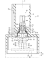
- FIG. 2 is a sectional view taken along the line II--II in FIG.
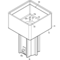
- FIG. 3 is a perspective view showing the second case and the connector from inside.
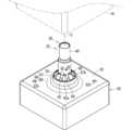
- FIG. 4 is a perspective view of the connector from the outside.
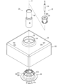
- FIG. 5 is an exploded perspective view of the connector.
- FIG. 6 is a rear view of the connector.
- the connector of the present disclosure is as follows.
- a terminal module including an inner conductor, an insulator surrounding the inner conductor, and a cylindrical outer conductor surrounding the insulator, and a connection having an opening that extends around the central axis of the outer conductor.
- a connector comprising a mating conductor and a plurality of spring connection parts arranged along the circumferential direction of the outer conductor on the outer circumference side of the outer conductor, the plurality of spring connection parts arranged along the circumferential direction of the outer conductor. When viewed along the central axis of the outer conductor, each of the plurality of spring connection parts extends from the edge of the opening toward the outer conductor side and extends to the outer periphery of the outer conductor.
- a connector that is elastically pressed.
- the outer conductor and the connecting partner conductor can be electrically connected more reliably by the spring connecting portion.
- Each of the plurality of spring connection parts extends from the edge of the opening toward the outer conductor and is elastically pressed against the outer periphery of the outer conductor, when viewed along the central axis of the outer conductor. Therefore, it is easy to reduce the gap between the spring connection parts. Thereby, the gap between the outer conductor and the connection partner conductor can be reduced as much as possible to improve electromagnetic shielding properties.
- the connector according to (1) which includes an annular portion along the opening and the plurality of spring connection portions, and includes an intervening member that is a separate member from the outer conductor and the connection partner conductor;
- the annular portion may be electrically connected to the connection partner conductor at the outer periphery of the opening, and the plurality of spring connection portions may be supported by the annular portion such that a spring fulcrum is a location where the plurality of spring connection portions connect to the annular portion. good.
- the spring connection part is formed in an intervening member that is a separate member from the outer conductor and the connection partner conductor, the spring connection part can be easily formed.
- annular portion includes an intervening cylindrical portion having a first opening and a second opening, and a projecting portion extending outward from an edge of the first opening;
- the projecting portion is in contact with one of the main surfaces of the connection partner conductor at the outer periphery of the opening, and the plurality of spring connection portions are supported by the edge of the second opening and extend toward the inside thereof.
- the plurality of spring connection parts can be brought into contact with the outer conductor at different positions along the axial direction of the outer conductor with respect to the opening of the connection partner conductor. Thereby, the degree of freedom in arranging the outer conductor with respect to the opening can be increased.
- each of the plurality of spring connection parts may have a shape that is narrower at the distal end than at the base end. Thereby, interference between the tips of the plurality of spring connection parts can be suppressed.
- each of the plurality of spring connection parts may have a gradually decreasing width part that gradually becomes narrower toward the distal end side. good. Thereby, in the gradually decreasing width portion, the gaps between the plurality of spring connection parts can be made as small as possible while making it difficult for the tips of the plurality of spring connection parts to interfere with each other.
- the plurality of spring connection parts may be evenly distributed along the edge of the opening when viewed along the central axis of the outer conductor. Thereby, each spring connection part is pressed against the outer conductor in a well-balanced manner.
- the plurality of spring connection parts are attached to the outer periphery of the outer conductor at the same position in a direction along the central axis of the outer conductor. It may be pressed. Thereby, the gap between the spring connection parts can be further reduced.
- each of the plurality of spring connection parts includes a spring body that extends diagonally with respect to the central axis of the outer conductor, and a spring body that extends diagonally with respect to the central axis of the outer conductor. and a contact tip connected to the tip of the spring body, and the contact tip may extend from the tip of the spring body in a direction diagonal to the central axis of the outer conductor and away from the central axis. This makes it easy to insert the outer conductor into the portion surrounded by the plurality of spring connections.
- FIG. 1 is a perspective view of a device 10 including a connector 30.
- FIG. 2 is a sectional view taken along the line II--II in FIG.
- the device 10 is, for example, a camera device.
- the camera device is, for example, an in-vehicle device.
- the device 10 does not have to be a camera device.
- the device 10 includes a case 12, an electrical component 20, and a connector 30.
- An electrical component 20 is housed within the case 12.
- the connector 30 is a connector for connecting the electrical component 20 and an external electrical component.
- the connector 30 is a connector to which a cable connected to an external electrical component is connected.
- the cable to which the connector 30 is connected is, for example, a coaxial cable.
- the case 12 includes a first case 13 and a second case 14.
- the first case 13 and the second case 14 are made of resin, for example.
- the first case 13 and the second case 14 are combined to form a rectangular parallelepiped box-shaped case 12 that accommodates the electrical component 20.
- the device 10 is a camera device, it is assumed that the first case 13 has an imaging lens or window, and the second case 14 has a connector 30.
- the electrical component 20 is, for example, a mounting board on which electronic components are mounted.
- the electrical components 20 are assumed to be a circuit board 21 and an image sensor 22 mounted on the circuit board 21.
- the image sensor 22 faces an imaging lens or window of the first case 13, and rotates the lens or window to image the outside scenery.
- the first case 13 side toward which the image sensor 22 faces may be referred to as the front side
- the second case 14 side opposite to the first case 13 side may be referred to as the rear side.
- the electrical component 20 includes a board-side connector 24 located on the surface of the circuit board 21 opposite to the image sensor 22.
- the board-side connector 24 includes, for example, a board-side inner conductor 25, a board-side insulator 26, and a board-side outer conductor 27.
- a substrate-side insulator 26 surrounds the substrate-side inner conductor 25 .
- a dielectric can be understood as a type of insulator, and the substrate-side insulator 26 may be a dielectric.
- a substrate-side outer conductor 27 surrounds the substrate-side insulator 26 .
- the board-side connector 24 protrudes from the circuit board 21 toward the connector 30.
- a relay connector 90 is connected to the board side connector 24.
- the relay connector 90 includes, for example, a movable inner conductor 91, a movable insulator 92, and a movable outer conductor 93.
- a movable inner conductor 91 is surrounded by a movable insulator 92 .
- a dielectric can be understood as a type of insulator, and the movable insulator 92 may be a dielectric.
- a movable outer conductor 93 surrounds the movable insulator 92 .
- the relay connector 90 is connected to the board-side connector 24 with the movable-side inner conductor 91 being inserted and connected to the board-side inner conductor 25 and the board-side outer conductor 27 being inserted and connected to the movable-side outer conductor 93. .
- the relay connector 90 further protrudes from the board-side connector 24 toward the connector 30.
- a relay connector 90 connects the board-side connector 24 and the connector 30 via relay.
- the relay connector 90 is connected to the board-side connector 24 and the connector 30 so that its posture can be changed.
- the connector 30 is provided on the second case 14 side, that is, on the rear side of the case 12. Inside the case 12, a relay connector 90 is connected to the connector 30. When a cable from the outside is connected to the connector 30, the external electrical component to which the cable is connected is electrically connected to the electrical component 20 inside the case 12.
- FIG. 3 is a perspective view showing the second case 14 and the connector 30 from inside.
- FIG. 4 is a perspective view showing the connector 30 from the outside.
- FIG. 5 is an exploded perspective view of the connector 30.
- FIG. 6 is a rear view of the connector 30.
- the connector 30 includes a terminal module 32, a mating conductor 50, and a plurality of spring connection parts 62.
- the terminal module 32 includes an inner conductor 34, an insulator 36, and an outer conductor 40.
- Insulator 36 surrounds inner conductor 34 .
- a dielectric can be understood as a type of insulator, and the insulator 36 may be a dielectric.
- the outer conductor 40 is formed into a cylindrical shape and surrounds the insulator 36.
- connection partner conductor 50 is a conductor to which the outer conductor 40 is electrically connected, and is made of metal or the like.
- the connection partner conductor 50 is a shield conductor that electromagnetically shields between the electric component 20 and the outside. More specifically, the connection partner conductor 50 is formed in the shape of a rectangular parallelepiped box with one side open, and is arranged along the inner surface of the second case 14 . By positioning the connection partner conductor 50 at the rear of the electrical component 20, it is possible to electromagnetically shield between the electrical component 20 and the rear outside thereof.
- the connection mating conductor 50 surrounds the board-side connector 24 and the relay connector 90 and is located at the rear, thereby electromagnetically shielding between the board-side connector 24 and the relay connector 90 and the outside around and behind them. can do.
- the connection partner conductor 50 may be formed by deep drawing a metal material, by pressing a metal plate, by molding, or by cutting. may be formed by.
- connection partner conductor 50 has the above shape; for example, the connection partner conductor may be formed in a plate shape that extends along the inner surface of the bottom of the second case 14. The connection partner conductor may be extended toward the first case 13 side. The connection partner conductor may be electrically connected to the shield conductor on the first case 13 side.
- the terminal module 32 is supported by the bottom 15 of the second case 14.
- a mating conductor 50 is also supported within the second case 14 .
- a configuration in which the second case 14 supports the terminal module 32 and the connection partner conductor 50 will be described.
- the bottom portion 52 of the connection partner conductor 50 is formed in a shape that extends over the entire inner surface of the bottom portion 15 of the second case 14, in this case, a rectangular shape.
- a hole 52h is formed in the bottom 52.
- a fixing protrusion 15p that can be fitted into the hole 52h is protruded from the inner surface of the bottom 15 of the second case 14.
- the mating conductor 50 is supported within the second case 14 by fitting the fixing protrusion 15p into the hole 52h.
- the fixing protrusion 15p may be press-fitted into the hole 52h.
- the tip of the fixing protrusion 15p is melted by heat, etc., and the melted and solidified portion is held at the periphery of the hole 52h in a state where it is not removed. It may be stuck.
- a retaining protrusion is formed at the tip of the fixing protrusion 15p, and the retaining protrusion is formed in the hole by utilizing elastic deformation of the peripheral edge of the fixing protrusion 15p or the hole 52h.
- the fixing protrusion 15p may be inserted into the hole 52h by pulling out the portion 52h.
- connection partner conductor may be fixed to the second case 14 with screws, adhesive, or the like.
- a holding cylinder portion 16 is provided protruding from the bottom portion 15.
- the holding cylinder portion 16 is a cylinder and projects outward from the center of the bottom portion 15 .
- the inner opening of the holding cylinder part 16 opens into the second case 14, and the outer opening of the holding cylinder part 16 opens to the outside of the second case 14.
- a holding partition portion 17 is formed in the axially intermediate portion of the holding cylinder portion 16 .
- the holding partition part 17 is formed in the axially intermediate part of the holding cylinder part 16 at a position closer to the inner opening.
- the holding partition part 17 partitions a space on the inner opening side of the holding cylinder part 16 and a space on the outer opening side.
- a holding hole 17h is formed in the holding partition 17, and the terminal module 32 is inserted and held in the holding hole 17h.
- a locking protrusion 18a for holding a cable connector attached to an end of a cable is formed on the outer circumference of the holding cylinder 16. It is not essential that the locking protrusion 18a be formed.
- the terminal module 32 will be explained in more detail. As described above, the terminal module 32 includes an inner conductor 34, an insulator 36, and an outer conductor 40.
- the inner conductor 34 is formed into an elongated rod shape and is made of a conductive material such as metal. In this embodiment, the longitudinally intermediate portion of the inner conductor 34 is thicker than both ends of the inner conductor 34 .
- the inner conductor 34 may be formed into a rod shape with a uniform thickness.
- the insulator 36 is formed of an insulator such as resin, and surrounds the inner conductor 34.
- the insulator 36 is a dielectric.
- the insulator 36 is formed into a columnar shape.
- the length of the insulator 36 is shorter than the length of the inner conductor 34.
- a through hole 36h is formed in the center of the insulator 36 along its extending direction.
- the inner conductor 34 is inserted into the through hole 36h, and the longitudinally intermediate portion of the inner conductor 34 is held within the through hole 36h. With the inner conductor 34 held by the insulator 36, both ends of the inner conductor 34 protrude outward from both end surfaces of the insulator 36.
- the inner conductor 34 may be formed with a locking protrusion that is hooked onto the inner circumferential surface of the through hole 36h.
- the outer conductor 40 is made of a conductive material such as metal.
- the outer conductor 40 is formed into a cylindrical shape surrounding the insulator 36. More specifically, the outer conductor 40 is formed into a cylindrical shape.
- the length of the outer conductor 40 is greater than the length of the insulator 36.
- the diameter of the outer portion of the outer conductor 40 is smaller than the outer diameter of the inner portion in accordance with the thickness of the relay connector 90 or the connector at the end of the cable.
- the outer conductor 40 may have a cylindrical shape with a uniform diameter, or the relationship between the thicknesses may be opposite to that described above.
- the insulator 36 is held at an intermediate portion in the longitudinal direction of the outer conductor 40, and both ends of the outer conductor 40 protrude further outward than both ends of the insulator 36.
- a locking protrusion may be formed on the outer conductor 40 to be hooked to either the outer peripheral surface or each end surface of the insulator 36.
- the outer conductor 40 may be formed by deep drawing a metal material, by pressing a metal plate, by molding, or by cutting. may be formed by.
- the outer conductor 40 is inserted into the holding hole 17h of the holding partition 17, and the longitudinally intermediate portion of the outer conductor 40 is held by the holding hole 17h.
- the outer conductor 40 may be held by a frictional holding force between the outer circumferential surface of the outer conductor 40 and the inner circumferential surface of the holding hole 17h.
- a protrusion may be formed on the outer conductor 40 to be caught on the inner peripheral portion of the holding hole 17h.
- the outer conductor 40 may be fixed to the holding hole 17h with adhesive, screws, or the like.
- annular recess 17g is formed in a portion of the holding partition 17 on the connection partner conductor 50 side and around the holding hole 17h. Therefore, the space S on the side of the connection mating conductor 50 from the holding partition part 17 in the holding cylinder part 16 is the cylindrical space S1 in the annular recess 17g, and the space S on the side of the connection mating conductor 50 from the columnar space S1. It includes a cylindrical space S2 that is larger than the cylindrical space S1.
- the movable outer conductor 93 of the relay connector 90 is inserted and connected to the inner opening of the outer conductor 40, and the inner end of the inner conductor 34 is inserted and connected to the movable inner conductor 91, so that the relay connector 90 and the connector 30 are connected within the case 12.
- the inner opening of the outer conductor 40 is located outside the bottom 15 of the mating conductor 50. Therefore, the outer end of the relay connector 90 is inserted into the space S, and the connection between the relay connector 90 and the connector 30 is made within the space S. As a result, part of the length required to connect the board-side connector 24, the relay connector 90, and the connector 30 can be placed inside the holding cylinder part 16, and the holding cylinder part 16 is excluded from the case 12. The front and back length of the part can be shortened. This allows the device 10 to be downsized as a whole.
- the inner opening of the outer conductor 40 may be formed longer and may be located at the same position as the bottom part 15 of the connection partner conductor 50 or located inside the bottom part 15.
- the other end of the outer conductor 40 protrudes outward from the holding partition 17.
- the outer conductor of the connector on the cable side is connected to the outer end of the outer conductor 40, and the outer end of the inner conductor 34 is inserted and connected to the inner conductor of the connector on the cable side.
- the connection partner conductor 50 has an opening 54 that extends around the central axis of the outer conductor 40.
- the connector 30 includes a plurality of spring connecting portions 62 arranged along the circumferential direction of the outer conductor 40 on the outer circumferential side of the outer conductor 40 .
- Each of the plurality of spring connection parts 62 extends from the edge of the opening 54 toward the outer conductor 40 side when viewed along the central axis X of the outer conductor 40 and is elastically pressed against the outer periphery of the outer conductor 40. ing.
- the spring connecting portion 62 is located between the outer circumference of the outer conductor 40 and the edge of the opening 54 when viewed along the central axis X of the outer conductor 40.
- the spring fulcrum 62a of the spring connection portion 62 is located closer to the edge of the opening 54 than the outer periphery of the outer conductor 40.
- the spring connecting portion 62 is elastically deformed about the spring fulcrum 62a, and can largely displace the end portion of the outer conductor 40 on the outer peripheral side.
- the spring connecting portion 62 is configured as a part of an intervening member 60 that is a separate member from the outer conductor 40 and the connecting partner conductor 50.
- an opening 54 is formed in the bottom 52 of the connection partner conductor 50.
- the opening 54 is formed at a position facing the inner opening of the outer conductor 40.
- the size of the opening 54 is the same as or larger than the inner opening of the outer conductor 40.
- the center of the opening 54 is located on the central axis of the outer conductor 40.
- connection partner conductor 50 has an extension tube portion 55 extending outward from the edge of the opening 54.
- the length of the extension cylinder part 55 is shorter than the axial length of the cylindrical space S2 located inside the holding cylinder part 16.
- the extension tube portion 55 is arranged within the columnar space S2. In this arrangement state, the tip of the extension tube portion 55 is separated from the inner part of the cylindrical space S2.
- the intervening member 60 includes an annular portion 66 and a plurality of spring connection portions 62.
- the intervening member 60 may be formed by deep drawing a metal material, by pressing a metal plate, by molding, or by cutting. may be formed. In any case, the intervening member 60 is a separate member from the outer conductor 40 and the connection partner conductor 50.
- the annular portion 66 is formed in an annular shape along the opening 54.
- the annular portion 66 is arranged along the opening 54 and is electrically connected to the mating conductor 50 at the outer periphery of the opening 54 .
- annular portion 66 is located away from the outer peripheral portion of the outer conductor 40 to the outside.
- An annular portion 66 supports a plurality of spring connections 62 at each location along opening 54 .
- the plurality of spring connection parts 62 are supported on the outer circumferential side of the outer conductor 40 so as to be lined up along the circumferential direction of the outer conductor 40 .
- the annular portion 66 supports each spring connecting portion 62 in a cantilevered manner in a posture facing the outer conductor 40 side.
- the spring connecting portion 62 is supported in a posture toward the outer conductor 40 side from the spring fulcrum 62a with the portion connected to the annular portion 66 as the spring fulcrum 62a.
- the annular portion 66 has an intervening cylindrical portion 67 and a projecting portion 68.
- the intervening cylindrical portion 67 is formed into a cylindrical shape.
- the outer diameter of the intervening cylindrical portion 67 is the same as or smaller than the diameter of the opening 54.
- the outer diameter of the intervening cylindrical portion 67 is set to such an extent that the intervening cylindrical portion 67 is positioned within the opening 54 in a direction orthogonal to the axial direction of the intervening cylindrical portion 67 when the intervening cylindrical portion 67 is inserted into the opening 54. , is preferably about the same diameter as the opening 54.
- the axial length of the intervening cylindrical portion 67 is shorter than the axial length of the columnar space S2. Thereby, a space is provided between the intervening cylindrical portion 67, the tip, and the inner part of the cylindrical space S2, in which the spring connecting portion 62 extends.
- the spring connection part 62 is arranged in the columnar space S1 from the back side of the columnar space S2.
- the axial length of the intervening cylindrical portion 67 is set to be the same as the axial length of the extension cylindrical portion 55.
- the intervening cylindrical portion 67 is disposed within the extension cylindrical portion 55 with the outer circumferential surface of the intervening cylindrical portion 67 in contact with the inner circumferential surface of the extension cylindrical portion 55 .
- the inner opening of the interposed cylinder portion 67 is the first opening 67a.
- the first opening 67a is continuous with the bottom portion 52 of the mating conductor 50 and opens into the mating conductor 50.
- the outer opening of the intervening cylindrical portion 67 is the second opening 67b.
- the second opening 67b extends toward the back side of the columnar space S2.
- the second opening 67b is located inside the outer opening of the extension tube portion 55.
- the second opening 67b and the inner opening of the holding cylinder portion 16 are located at the same position in the direction along the central axis of the outer conductor 40, but this is not essential.
- the projecting portion 68 extends outward from the edge of the first opening 67a.
- the projecting portion 68 is formed in an annular plate shape.
- the projecting portion may be formed into a polygonal plate shape.
- the projecting portion may extend outward from a part of the circumferential edge of the first opening. In that case, a plurality of projecting parts may be formed distributed along the circular edge of the first opening.
- the projecting portion 68 is located on the outer peripheral side of the opening 54 on the inner surface of the bottom portion 52 and is electrically connected to the bottom portion 52 .
- the overhanging portion 68 is electrically connected to the bottom portion 52 and fixed.
- the projecting portion may be soldered to the mating conductor.
- the overhanging portion may be caulked and fixed by pressing or the like while being superimposed on the bottom of the connection partner conductor.
- a concave portion may be formed on one side of the overhanging portion and the mating conductor to be connected, and a convex portion may be formed on the other side, and the convex portion may be fitted into the concave portion to fix the overhanging portion and the mating conductor to each other in contact with each other. good.
- the intervening cylindrical portion 67 passes through the opening 54 and protrudes toward the other main surface of the bottom 52 of the mating conductor 50 .
- the intervening tube portion 67 passes through the extension tube portion 55.
- the projecting portion 68 is fixed to the inner surface of the bottom portion 52, but may be fixed to the outer surface of the bottom portion 52.
- the overhanging portion 68 is directly fixed to the bottom portion 52 and is electrically connected to the mating conductor 50 to be connected. It is not essential that the overhang 68 be directly fixed to the bottom 52.
- the projecting portion is sandwiched between the bottom of the connection partner conductor and the bottom of the second case, and is maintained in a state in which it contacts the connection partner conductor and is electrically connected to the connection partner conductor. Good too.
- the plurality of spring connecting portions 62 are supported by the edge of the second opening 67b of the intervening cylinder portion 67 and extend toward the inside thereof.
- the plurality of spring connection parts 62 are evenly distributed along the edge of the opening 54 (second opening 67b).
- the eight spring connection parts 62 are evenly distributed along the edge of the opening 54 (second opening 67b) at 45 degree intervals around the central axis X of the outer conductor 40.
- uniformity includes uniformity within a manufacturing error range (for example, the intervals differ within a range of ⁇ 5 degrees around the central axis X of the outer conductor 40). It is not essential that the plurality of spring connections be evenly distributed along the edge of the opening 54 (second opening 67b).
- the base ends (spring fulcrums 62a) of adjacent spring connection parts 62 are separated from each other in the direction along the edge of the second opening 67b. Thereby, interference between adjacent spring connecting portions 62 is more reliably suppressed. Note that it is not essential that the proximal ends (spring fulcrums) of adjacent spring connection parts be separated from each other.
- Each spring connection portion 62 has an elongated shape when viewed as a whole, and extends from the second opening 67b toward the outer periphery of the outer conductor 40. That is, when viewed along the central axis X of the outer conductor 40, the spring connecting portion 62 extends along the radial direction of a circle centered on the central axis X of the outer conductor 40.
- the outer circumferential end of the spring connecting portion 62 is a spring fulcrum 62 a that is connected to the second opening 67 b of the intervening member 60 .
- An end of the spring connecting portion 62 on the inner circumferential side is pressed against the outer circumferential portion of the outer conductor 40 .
- the spring connecting portion 62 is formed to have a narrower shape at the distal end than at the proximal end.
- the spring connection portion 62 includes a spring body 63 and a contact tip portion 64 .
- the spring body 63 By forming the spring body 63 into a shape that gradually becomes narrower toward the distal end, the distal end of the spring connecting portion 62 is narrower than the base end.
- the spring body 63 extends from a spring fulcrum 62a connected to the second opening 67b in a direction intersecting the central axis X of the outer conductor 40, here, in a diagonal direction.
- the spring body 63 is a plate-shaped portion that slopes outward from the spring fulcrum 62a toward the outer peripheral portion of the outer conductor 40.
- the spring body 63 is formed in a shape that gradually becomes narrower toward the tip side.
- the spring body 63 is an example of a gradually decreasing width portion that gradually becomes narrower toward the distal end side.
- the spring body 63 is formed into an isosceles trapezoid shape, with the side on the spring fulcrum 62a side serving as the longer lower base, and the side on the tip side serving as the shorter upper base.
- the length of the spring body 63 is set to be larger than the length obtained by subtracting the radius of the outer conductor 40 from the radius of the second opening 67b, and the spring body 63 is in an oblique position with respect to the central axis X of the outer conductor 40. , the outer periphery of the outer conductor 40 can be reached through the second opening 67b.
- the spring body 63 is formed in a shape that gradually becomes narrower toward the distal end, it is possible to reduce the gap between adjacent spring connecting portions 62 while suppressing interference between adjacent spring connecting portions 62. That is, assume that the spring body is formed into a shape with a constant width. In this case, in order to avoid interference between the tips of the spring bodies, it is conceivable to make the entire spring body thinner. In this case, the distance between the base ends of adjacent spring bodies becomes large. Conversely, in order to reduce the gap between adjacent spring bodies, it is conceivable to make the entire spring body wide. In this case, the tips of adjacent spring bodies interfere with each other. For this reason, with spring bodies of equal width, it may be difficult to avoid interference between the tips and reduce the gap between the spring bodies. On the other hand, if the spring body 63 is formed in a shape that gradually becomes narrower toward the tip side, it is possible to avoid interference between the tips and to reduce the gap between the spring bodies 63. hardly compatible.
- the springiness of the spring body can be adjusted by the width of the spring body. Since the spring body 63 has a gradually decreasing width portion that gradually becomes narrower toward the distal end side, the springiness of the spring connecting portion 62 can be adjusted.
- the entire spring body does not need to be the gradually decreasing width portion.
- a portion of the spring body may be a gradually decreasing width portion.
- the proximal end portion of the spring body may have a uniform width
- the distal end portion may have a gradually decreasing width.
- the contact tip 64 is continuous with the tip of the spring body 63.
- the contact tip portion 64 is a portion formed by bending a portion of the spring body 63 that extends toward the tip side.
- the spring body 63 and the contact tip 64 are connected in a V-shape.
- the spring body 63 and the contact tip portion 64 are connected in a curved manner, and the outer side of the curved portion is pressed against the outer peripheral portion of the outer conductor 40 .
- the contact tip portion 64 extends from the tip of the spring body 63 in a direction diagonal to the central axis X of the outer conductor 40 and away from the central axis X. In other words, the contact tip portion 64 is inclined in a direction away from the central axis X as it goes outward along the central axis X. Therefore, when the outer conductor 40 is inserted into the tip side of the plurality of spring connection parts 62, the inward facing surface of the contact tip part 64 is pressed against the outer circumference of the outer conductor 40, and the spring connection parts 62 are easily pushed to the outer circumference side. It will be expanded. Thereby, the outer conductor 40 can be easily inserted between the plurality of spring connection parts 62 arranged in a ring shape.
- the contact tip portion 64 is formed to have a uniform width. Further, the tip side corner portion of the contact tip portion 64 is formed in a rounded shape. It is not essential that the contact tip 64 be formed in this shape.
- the plurality of spring connection parts 62 are formed in the same shape. That is, the plurality of spring connection parts 62 are formed in a rotationally symmetrical shape with the central axis X as the axis of symmetry. Therefore, with the outer conductor 40 inserted into the center of the plurality of spring connection parts 62, the plurality of spring connection parts 62 are deformed into a similar shape. Thereby, the plurality of spring connecting portions 62 are pressed against the outer peripheral portion of the outer conductor 40 at the same position in the direction along the central axis X of the outer conductor 40.
- the same position here includes the same position within a manufacturing error range (for example, within 5 mm in the direction along the central axis X).
- the positions along the central axis X will differ between adjacent spring connecting portions 62. It is difficult for gaps to occur due to this. Thereby, the gap between adjacent spring connection parts 62 can be made as small as possible.
- each of the plurality of spring connection parts 62 arranged along the circumferential direction of the outer conductor 40 on the outer circumferential side of the outer conductor 40 is arranged along the central axis X of the outer conductor 40. As seen, it extends from the edge of the opening 54 (second opening 67b) toward the outer conductor 40 and is elastically pressed against the outer periphery of the outer conductor 40. Therefore, even if the relative position between the connecting mating conductor 50 and the outer conductor 40 changes due to manufacturing errors, thermal expansion and contraction of the second case 14, etc., the spring connecting portion 62 can be stably connected with the spring. 62.
- each of the plurality of spring connection parts 62 extends from the edge of the opening 54 (second opening 67b) toward the outer conductor side when viewed along the central axis X of the outer conductor 40, so that the spring connection part It is easy to reduce the gap between 62.
- the spring connection portion extends from the outer conductor 40 toward the edge of the opening 54 (second opening 67b) and is pressed against the extension tube portion of the connection partner conductor. In this case, it is assumed that it is difficult to make the distal end of the spring connection part thicker than the proximal end.
- each spring connection part 62 can be formed by dividing a cylinder part obtained by extending the intervening cylinder part 67 along the circumferential direction and bending each divided part inward. Therefore, the gap between adjacent spring connecting portions 62 can be made as small as possible. Thereby, the gap can be made as small as possible at the portion where the outer conductor 40 and the connection partner conductor 50 are connected, and electromagnetic shielding properties can be improved.
- a gap may be formed between adjacent spring connection parts 62 to prevent the spring connection parts 62 from interfering with each other, or a gap due to processing restrictions.
- the gap between adjacent spring connection parts 62 is preferably set to a size that can effectively shield the frequency range that is the main target of shielding. Further, adjacent spring connection portions may partially overlap each other.
- the spring connection portion 62 is formed in the intervening member 60 which is a separate member from the outer conductor 40 and the mating conductor 50, it is not limited by manufacturing restrictions of the outer conductor 40 and the mating conductor 50. , the spring connection portion 62 having the desired springiness can be easily formed. For example, if the mating conductor 50 is manufactured by drawing in order to eliminate gaps, improve electromagnetic shielding, and reduce costs, it is difficult to control the thickness of the mating conductor 50. For this reason, it may be difficult to form a spring connection portion having desired spring properties on the connection partner conductor 50. If the intervening member 60 is a separate member from the mating conductor 50, it is possible to easily form the spring connection portion 62 with desired springiness and an arbitrary thickness regardless of these restrictions.
- a projecting portion 68 extending outward from the edge of the first opening 67a of the intervening cylindrical portion 67 is in contact with one of the main surfaces of the connection partner conductor 50 at the outer periphery of the opening 54, and the plurality of spring connecting portions 62 is supported by the edge of the second opening 67b and extends inward. Therefore, the plurality of spring connection parts 62 can be brought into contact with the outer conductor 40 at different positions along the axial direction of the outer conductor 40 with respect to the opening 54 of the connection partner conductor 50. Thereby, the degree of freedom in arranging the outer conductor 40 with respect to the opening 54 can be increased.
- the inner opening of the outer conductor 40 can be located inside the holding cylinder part 16 on the outside with respect to the inner space of the second case 14.
- the connecting portion between the outer conductor 40 and the relay connector 90 is disposed within the holding cylinder portion 16, so that the longitudinal length of the case 12 can be reduced, and the case 12 as a whole can be made smaller.
- the intervening member 60 can be firmly fixed to the connecting partner conductor 50.
- each of the plurality of spring connection parts 62 has a shape in which the contact tip part 64 located at the tip is narrower than the spring fulcrum 62a located at the base end, the tips of the plurality of spring connection parts 62 The contact tip portion 64 can be more reliably pressed against the outer periphery of the outer conductor 40 while suppressing interference.
- the spring connecting parts 62 are along the radial direction of a circle centered on the central axis X when viewed along the central axis X of the outer conductor 40, the spring connecting parts 62 are oriented toward the central axis X. This makes it easy to apply a pressing force to the outer periphery of the outer conductor 40.
- each spring connection part 62 is It is pressed against the outer conductor 40 in a well-balanced manner.
- the plurality of spring connecting portions 62 are pressed against the outer peripheral portion of the outer conductor 40 at the same position in the direction along the central axis X. Therefore, gaps between the spring connecting parts 62 due to differences in height of the spring connecting parts 62 in the direction along the central axis X are less likely to occur, and the gaps between the spring connecting parts 62 can be further reduced.
- each of the plurality of spring connection parts 62 includes a contact tip part 64 extending from the tip of the spring body 63 in a direction diagonal to the central axis X of the outer conductor 40 and away from the central axis X, the plurality of spring connections The outer conductor 40 can be easily inserted into the portion surrounded by the portion 62.
- the spring connection portion 62 is a separate member from the connection partner conductor 50.
- the spring connection portion may be a portion integrally formed with the connection partner conductor.
- the spring connection portion may be formed so as to face inward from the opening of the connection partner conductor.
- the connector 30 is connected to a coaxial cable, and an example in which the connector includes one inner conductor has been described.
- the connector is also assumed to include a plurality of inner conductors.
- the connector 30 may be applied to connect cables to electrical components other than the device 10.
- the intervening cylindrical portion 67 of the intervening member 60 may be omitted, and the plurality of spring connecting portions 62 may extend toward the outer conductor 40 with the edge of the opening of the overhanging portion 68 as the base end. Further, the outer conductor 40 may extend along the central axis X at the same position as the opening 54 of the connection partner conductor 50 or inward from the opening 54.
- the number of the spring connecting portions 62 is arbitrary.
- two or more spring connections 62 may be provided around the central axis X.
- the distribution of the plurality of spring connecting portions 62 around the central axis X is arbitrary.
Landscapes
- Coupling Device And Connection With Printed Circuit (AREA)
- Details Of Connecting Devices For Male And Female Coupling (AREA)
Priority Applications (1)
| Application Number | Priority Date | Filing Date | Title |
|---|---|---|---|
| CN202380039165.7A CN119174066A (zh) | 2022-05-27 | 2023-05-08 | 连接器 |
Applications Claiming Priority (2)
| Application Number | Priority Date | Filing Date | Title |
|---|---|---|---|
| JP2022086609A JP7757876B2 (ja) | 2022-05-27 | 2022-05-27 | コネクタ |
| JP2022-086609 | 2022-05-27 |
Publications (1)
| Publication Number | Publication Date |
|---|---|
| WO2023228706A1 true WO2023228706A1 (ja) | 2023-11-30 |
Family
ID=88919041
Family Applications (1)
| Application Number | Title | Priority Date | Filing Date |
|---|---|---|---|
| PCT/JP2023/017248 Ceased WO2023228706A1 (ja) | 2022-05-27 | 2023-05-08 | コネクタ |
Country Status (3)
| Country | Link |
|---|---|
| JP (1) | JP7757876B2 (enExample) |
| CN (1) | CN119174066A (enExample) |
| WO (1) | WO2023228706A1 (enExample) |
Families Citing this family (1)
| Publication number | Priority date | Publication date | Assignee | Title |
|---|---|---|---|---|
| JP2025167929A (ja) * | 2024-04-26 | 2025-11-07 | 山一電機株式会社 | 中継コネクタ、実装コネクタ及びコネクタアセンブリ |
Citations (2)
| Publication number | Priority date | Publication date | Assignee | Title |
|---|---|---|---|---|
| JP2020061340A (ja) * | 2018-10-12 | 2020-04-16 | ヒロセ電機株式会社 | 中継コネクタおよびカメラモジュール |
| JP2021190375A (ja) * | 2020-06-03 | 2021-12-13 | ホシデン株式会社 | シールド部材、シールドユニット、及びコネクタモジュール |
-
2022
- 2022-05-27 JP JP2022086609A patent/JP7757876B2/ja active Active
-
2023
- 2023-05-08 CN CN202380039165.7A patent/CN119174066A/zh active Pending
- 2023-05-08 WO PCT/JP2023/017248 patent/WO2023228706A1/ja not_active Ceased
Patent Citations (2)
| Publication number | Priority date | Publication date | Assignee | Title |
|---|---|---|---|---|
| JP2020061340A (ja) * | 2018-10-12 | 2020-04-16 | ヒロセ電機株式会社 | 中継コネクタおよびカメラモジュール |
| JP2021190375A (ja) * | 2020-06-03 | 2021-12-13 | ホシデン株式会社 | シールド部材、シールドユニット、及びコネクタモジュール |
Also Published As
| Publication number | Publication date |
|---|---|
| JP7757876B2 (ja) | 2025-10-22 |
| CN119174066A (zh) | 2024-12-20 |
| JP2023174009A (ja) | 2023-12-07 |
Similar Documents
| Publication | Publication Date | Title |
|---|---|---|
| TWI761862B (zh) | 附有浮動機構的同軸連接器 | |
| JP7120469B2 (ja) | 電気コネクタおよび電気コネクタセット | |
| WO2024024452A1 (ja) | コネクタ | |
| WO2023228706A1 (ja) | コネクタ | |
| JP5071587B2 (ja) | 検査用同軸コネクタ | |
| JP6933382B2 (ja) | 同軸コネクタ、高周波ユニット及び受信装置 | |
| US12283782B2 (en) | Electronic component | |
| WO2023228707A1 (ja) | コネクタ | |
| US20180159258A1 (en) | Electronic Component and Imaging Device | |
| JP2020077483A (ja) | 電気コネクタ | |
| WO2025009390A1 (ja) | コネクタ | |
| JP7392688B2 (ja) | コネクタセット | |
| JP7363228B2 (ja) | コネクタ装置、コネクタ、及びコネクタ構造 | |
| JP2024175757A (ja) | 同軸コネクタの接続構造 | |
| US20230420890A1 (en) | Terminal unit, and connector including the same | |
| JP2024175752A (ja) | 同軸コネクタの接続構造 | |
| WO2025009389A1 (ja) | コネクタ | |
| WO2024209963A1 (ja) | 同軸コネクタ | |
| WO2025009360A1 (ja) | コネクタ | |
| JP2019050091A (ja) | 同軸コネクタ及び同軸コネクタセット | |
| WO2024253005A1 (ja) | 端子モジュール | |
| JP2024148286A (ja) | コネクタ | |
| JP2024166761A (ja) | 筒端子、同軸コネクタ及び筒端子の固定構造 | |
| JP2025008370A (ja) | コネクタ | |
| CN119234361A (zh) | 同轴连接器 |
Legal Events
| Date | Code | Title | Description |
|---|---|---|---|
| 121 | Ep: the epo has been informed by wipo that ep was designated in this application |
Ref document number: 23809961 Country of ref document: EP Kind code of ref document: A1 |
|
| WWE | Wipo information: entry into national phase |
Ref document number: 18869285 Country of ref document: US |
|
| NENP | Non-entry into the national phase |
Ref country code: DE |
|
| 122 | Ep: pct application non-entry in european phase |
Ref document number: 23809961 Country of ref document: EP Kind code of ref document: A1 |