WO2023228703A1 - 振動装置及び電子機器 - Google Patents
振動装置及び電子機器 Download PDFInfo
- Publication number
- WO2023228703A1 WO2023228703A1 PCT/JP2023/017228 JP2023017228W WO2023228703A1 WO 2023228703 A1 WO2023228703 A1 WO 2023228703A1 JP 2023017228 W JP2023017228 W JP 2023017228W WO 2023228703 A1 WO2023228703 A1 WO 2023228703A1
- Authority
- WO
- WIPO (PCT)
- Prior art keywords
- vibration device
- right direction
- viewed
- connecting portion
- curved
- Prior art date
- Legal status (The legal status is an assumption and is not a legal conclusion. Google has not performed a legal analysis and makes no representation as to the accuracy of the status listed.)
- Ceased
Links
Images




Classifications
-
- H—ELECTRICITY
- H03—ELECTRONIC CIRCUITRY
- H03H—IMPEDANCE NETWORKS, e.g. RESONANT CIRCUITS; RESONATORS
- H03H9/00—Networks comprising electromechanical or electro-acoustic elements; Electromechanical resonators
- H03H9/15—Constructional features of resonators consisting of piezoelectric or electrostrictive material
- H03H9/17—Constructional features of resonators consisting of piezoelectric or electrostrictive material having a single resonator
-
- B—PERFORMING OPERATIONS; TRANSPORTING
- B06—GENERATING OR TRANSMITTING MECHANICAL VIBRATIONS IN GENERAL
- B06B—METHODS OR APPARATUS FOR GENERATING OR TRANSMITTING MECHANICAL VIBRATIONS OF INFRASONIC, SONIC, OR ULTRASONIC FREQUENCY, e.g. FOR PERFORMING MECHANICAL WORK IN GENERAL
- B06B1/00—Methods or apparatus for generating mechanical vibrations of infrasonic, sonic, or ultrasonic frequency
- B06B1/02—Methods or apparatus for generating mechanical vibrations of infrasonic, sonic, or ultrasonic frequency making use of electrical energy
- B06B1/06—Methods or apparatus for generating mechanical vibrations of infrasonic, sonic, or ultrasonic frequency making use of electrical energy operating with piezoelectric effect or with electrostriction
-
- G—PHYSICS
- G06—COMPUTING OR CALCULATING; COUNTING
- G06F—ELECTRIC DIGITAL DATA PROCESSING
- G06F3/00—Input arrangements for transferring data to be processed into a form capable of being handled by the computer; Output arrangements for transferring data from processing unit to output unit, e.g. interface arrangements
- G06F3/01—Input arrangements or combined input and output arrangements for interaction between user and computer
-
- G—PHYSICS
- G06—COMPUTING OR CALCULATING; COUNTING
- G06F—ELECTRIC DIGITAL DATA PROCESSING
- G06F3/00—Input arrangements for transferring data to be processed into a form capable of being handled by the computer; Output arrangements for transferring data from processing unit to output unit, e.g. interface arrangements
- G06F3/01—Input arrangements or combined input and output arrangements for interaction between user and computer
- G06F3/03—Arrangements for converting the position or the displacement of a member into a coded form
- G06F3/041—Digitisers, e.g. for touch screens or touch pads, characterised by the transducing means
-
- H—ELECTRICITY
- H03—ELECTRONIC CIRCUITRY
- H03H—IMPEDANCE NETWORKS, e.g. RESONANT CIRCUITS; RESONATORS
- H03H9/00—Networks comprising electromechanical or electro-acoustic elements; Electromechanical resonators
- H03H9/02—Details
- H03H9/05—Holders or supports
Definitions
- the present invention relates to a vibration device and an electronic device including the vibration device.
- a vibration structure described in Patent Document 1 As an invention related to a conventional vibration device, for example, a vibration structure described in Patent Document 1 is known.
- the vibrating structure described in Patent Document 1 includes a film, a frame member, a vibrating section, a support section, a first connecting member, and a second connecting member.
- the frame member has a frame shape with an opening when viewed in the normal direction of the frame member.
- the vibrating section is located within the opening when viewed in the normal direction of the frame-shaped member.
- the support section connects the frame member and the vibrating section. By elastically deforming the support part, the vibrating part can be displaced with respect to the frame-shaped member.
- the film has a rectangular shape with a first end and a second end.
- the first connecting member fixes the first end of the film and the vibrating section.
- the second connecting member fixes the second end of the film and the frame member.
- the vibrating structure having the above structure, when a voltage is applied to the film, the film deforms so that the distance between the first end and the second end changes. Thereby, the vibrating section vibrates with respect to the frame-shaped member.
- an object of the present invention is to provide a vibrating device and electronic equipment that can improve the drop resistance of the vibrating device.
- a vibration device includes: A vibration device attached to a vibrated member,
- the vibration device is a support member; an actuator that vibrates the vibrated member in the left-right direction; It is equipped with
- the support member is a fixed part; a movable part having an upper principal surface and a lower principal surface aligned in the vertical direction; an elastic connecting part that elastically connects the fixed part and the movable part in the left-right direction; including;
- the movable part supports the vibrated member,
- the actuator is attached to the fixed part and the movable part or the vibrated member,
- the elastic connecting portion has a first elastic modulus in the left-right direction and a second elastic modulus in the up-down direction, The second elastic modulus is smaller than the first elastic modulus.
- direction is defined as follows.
- the up-down direction is the direction in which the normal line of the upper main surface US32 of the movable portion 32 extends.
- the left-right direction is the direction in which the actuator 4 vibrates the vibrated member 2 .
- the front-rear direction is the direction in which the first curved portion 331, the second curved portion 332, or the third curved portion 333 protrudes.
- the up-down direction, the left-right direction, and the front-back direction are orthogonal to each other. Note that the definition of direction in this specification is an example. Therefore, the direction in which the vibration device 10 is actually used does not need to match the direction in this specification.
- X and Y are parts or members of the electronic device 100.
- each part of X is defined as follows.
- the upper part of X means the upper half of X.
- the upper end of X means the upper end of X.
- the upper end of X means the upper end of X and its vicinity. This definition also applies to directions other than the upward direction.
- X is located above Y
- X is located directly above Y. Therefore, when viewed in the vertical direction, X overlaps Y.
- "X is located above Y” means that X is located directly above Y, and that X is located diagonally above Y. Therefore, when viewed in the vertical direction, X may or may not overlap Y. This definition also applies to directions other than the upward direction.
- the drop resistance of the vibrating device can be improved.
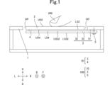
- FIG. 1 is a sectional view of the electronic device 100 viewed from the front.
- FIG. 2 is a plan view of the vibration device 10 viewed from below.
- FIG. 3 is a plan view of the support member 3 viewed from below.
- FIG. 4 is a plan view of the elastic connecting portion 33 viewed from below.
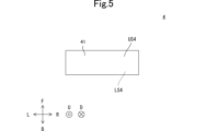
- FIG. 5 is a plan view of the actuator 4 viewed from below.
- FIG. 6 is a sectional view showing a situation in which the vibration device 1010 according to the comparative example falls and the vibration device 1010 according to the comparative example collides with the floor 6 in a state where the fixed part 31 is on the movable part 32.
- FIG. 7 is a cross-sectional view showing the directions of forces F1, F2, and F3 when the vibration device 10 collides with the floor 6 in a state where the fixed part 31 is on the movable part 32.
- FIG. 1 is a sectional view of the electronic device 100 viewed from the front.
- FIG. 2 is a plan view of the vibration device 10 viewed from below.
- FIG. 3 is a plan view of the support member 3 viewed from below.
- FIG. 4 is a plan view of the elastic connecting portion 33 viewed from below.
- FIG. 5 is a plan view of the actuator 4 viewed from below.
- FIG. 6 is a sectional view showing a situation in which the vibration device 1010 according to the comparative example falls and the vibration device 1010 according to the comparative example collides with the floor 6 in a state where the fixed part 31 is on the movable part 32.
- FIG. 7 is a cross-sectional view showing the directions of forces F1, F2, and F3 when the vibration device 10 collides with the floor 6 in a state where the fixed part 31 is on the movable part 32.
- the vibration device 10 is used, for example, in an electronic device 100 that provides tactile feedback to the user 200 by vibrating the vibrated member 2 when the user 200 presses the vibrated member 2. . Since the vibrated member 2 vibrates when the user 200 presses the vibrated member 2, the user 200 can feel that the vibrated member 2 has been pressed. In this way, the vibration device 10 is attached to the vibrated member 2.
- the housing 1 is a rectangular parallelepiped box. As shown in FIG. 1, the housing 1 is provided with an opening OP. More specifically, the opening OP has a rectangular shape when viewed in the vertical direction. As shown in FIG. 1, the opening OP passes through the upper surface of the housing 1 in the vertical direction.
- the vibrated member 2 has a plate shape, as shown in FIG. Therefore, the vibrated member 2 has an upper main surface US2 and a lower main surface LS2 that are arranged in the vertical direction.
- the upper main surface US2 is located above the lower main surface LS2.
- the upper main surface US2 and the lower main surface LS2 are parallel to each other.
- Each of the upper main surface US2 and the lower main surface LS2 has a rectangular shape with long sides extending in the left-right direction and short sides extending in the front-rear direction.
- the vertical position of the vibrated member 2 is equal to the vertical position of the upper surface of the housing 1, as shown in FIG. Further, the vibrated member 2 is located within the opening OP when viewed in the vertical direction. Thereby, the user 200 can press the upper main surface US2 of the vibrated member 2. Note that the vibrated member 2 is not in contact with the housing 1.
- the vibration device 10 includes a support member 3 and an actuator 4, as shown in FIG.
- the support member 3 includes a fixed part 31, a movable part 32, and an elastic connecting part 33, as shown in FIG.
- the movable part 32, the elastic connecting part 33, and the fixed part 31 are arranged in this order from left to right.
- the material of the support member 3 is metal such as SUS (Stainless Used Steel).
- the support member 3 is manufactured by punching a single SUS plate.
- the fixing part 31 is fixed to the housing 1, as shown in FIG. More specifically, the fixing part 31 has two screw holes 311, as shown in FIG.
- the fixing part 31 is fixed to the housing by inserting the bolts 5 from below each of the two screw holes 311 into each of the two screw holes 311 and into each of the two screw holes (not shown) of the housing 1. Fixed to body 1.
- the movable part 32 supports the vibrated member 2, as shown in FIG.
- the movable part 32 has an upper main surface US32 and a lower main surface LS32 that are arranged in the vertical direction.
- Upper main surface US32 is located above lower main surface LS32.
- the upper main surface US32 and the lower main surface LS32 are parallel to each other.
- each of the upper main surface US32 and the lower main surface LS32 has a rectangular shape with long sides extending in the left-right direction and short sides extending in the front-rear direction.
- the movable part 32 has a slit 321, as shown in FIG.
- the slit 321 passes through the movable portion 32 in the vertical direction.
- the slit 321 has a shape that extends in the front-rear direction when viewed in the up-down direction.
- the slit 321 has a rectangular shape with short sides extending in the left-right direction and long sides extending in the front-back direction.
- the slit 321 overlaps the elastic connecting portion 33 when viewed in the left-right direction.
- the elastic connecting portion 33 elastically connects the fixed portion 31 and the movable portion 32 in the left-right direction. More specifically, the movable part 32 is elastically connected to the fixed part 31 in the left-right direction via an elastic connecting part 33. Thereby, the movable part 32 can vibrate in any direction relative to the fixed part 31.
- the arbitrary direction is a left-right direction, a front-back direction, an up-down direction, or the like. Therefore, the elastic connecting portion 33 has a first elastic coefficient k1 in the left-right direction, and has a second elastic coefficient k2 in the up-down direction. Further, the second elastic coefficient k2 is smaller than the first elastic coefficient k1.
- the elastic connecting portion 33 has a first curved portion 331, a second curved portion 332, a third curved portion 333, a first connecting portion 334, and a second connecting portion 335.
- Each of the first curved section 331, the second curved section 332, and the third curved section 333 is elastically deformed.
- the first curved part 331, the second curved part 332, and the third curved part 333 are lined up in this order from left to right when viewed in the front-rear direction.
- the first curved portion 331 includes a shape that curves so as to protrude forward. Further, the left end portion of the first curved portion 331 has a shape extending in the front-rear direction. Therefore, the elastic connecting portion 33 includes a shape extending in the front-rear direction. Further, the right end portion of the first curved portion 331 has a shape extending from the front right direction to the rear left direction.
- the second curved portion 332 includes a shape that curves so as to protrude rearward. Further, the second curved portion 332 has an inner edge I332 and an outer edge O332.
- the inner edge I332 and the outer edge O332 are the inner edge of the arc and the outer edge of the arc, respectively. Therefore, the length of the outer edge O332 is longer than the length of the inner edge I332, and the radius of curvature of the outer edge O332 is equal to the radius of curvature of the inner edge I332.
- the left end portion of the second curved portion 332 has a shape extending from the front right direction to the rear left direction. Further, the right end portion of the second curved portion 332 has a shape extending from the front left direction to the rear right direction.
- the third curved portion 333 includes a shape that curves so as to protrude forward. Further, the left end portion of the third curved portion 333 has a shape extending from the front left direction to the rear right direction. Further, the right end portion of the third curved portion 333 has a shape extending in the front-rear direction.
- the shortest distance LRMIN13 in the left-right direction between the first curved part 331 and the third curved part 333 is shorter than the longest distance LRMAXO2 in the left-right direction of the outer edge O332 of the second curved part 332.
- the first connecting part 334 connects the movable part 32 and the first curved part 331, as shown in FIGS. 3 and 4. As shown in FIG. 4, the first connecting portion 334 has a shape extending in the first direction DIR1. Note that the first connecting portion 334 only needs to have a shape extending in the first direction DIR1.
- the first direction DIR1 forms a first angle ⁇ 1 counterclockwise with respect to the left-right direction when viewed in the up-down direction.
- the first angle ⁇ 1 is an angle greater than 0 degrees counterclockwise and less than 90 degrees counterclockwise. That is, the first direction DIR1 is different from the horizontal direction when viewed in the vertical direction.
- the first angle ⁇ 1 is an angle greater than 30 degrees counterclockwise and less than 90 degrees counterclockwise.
- the second connecting part 335 connects the fixed part 31 and the third curved part 333, as shown in FIGS. 3 and 4. As shown in FIG. 4, the second connecting portion 335 has a shape extending in the second direction DIR2. Note that the second connecting portion 335 only needs to have a shape extending in the second direction DIR2.
- the second direction DIR2 forms a second angle ⁇ 2 clockwise with respect to the left-right direction when viewed in the up-down direction.
- the second angle ⁇ 2 is an angle greater than 0 degrees clockwise and less than 90 degrees clockwise. That is, the second direction DIR2 is different from the left-right direction when viewed in the up-down direction.
- the second angle ⁇ 2 is an angle greater than 30 degrees clockwise and less than 90 degrees clockwise.
- the actuator 4 includes a piezoelectric film 41, a first electrode (not shown), and a second electrode (not shown).
- the actuator 4 has a film shape.
- the actuator 4 has a first main surface US4 and a second main surface LS4.
- the first main surface US4 is located on the second main surface LS4.
- the first main surface US4 and the second main surface LS4 are parallel to each other.
- the first main surface US4 is the upper surface of the first electrode.
- the second main surface LS4 is the lower surface of the second electrode.
- each of the first main surface US4 and the second main surface LS4 has a rectangular shape having a long side extending in the left-right direction and a short side extending in the front-rear direction when viewed in the vertical direction. .
- the piezoelectric film 41 is a piezoelectric body. That is, the actuator 4 includes a piezoelectric body. Moreover, the piezoelectric film 41 has an upper surface and a lower surface. The first electrode is provided on the top surface of the piezoelectric film 41 (not shown). The second electrode is provided on the lower surface of the piezoelectric film 41 (not shown). Each of the first electrode and the second electrode is a metal film formed by vapor deposition.
- the actuator 4 is attached to the fixed part 31 of the support member 3 and the movable part 32 of the support member 3, as shown in FIG. More specifically, the left end of the actuator 4 is attached to the movable part 32 via an adhesive (not shown) with the actuator 4 slightly stretched in the left and right direction, and the right end of the actuator 4 is attached to the movable part 32 via an adhesive (not shown).
- the actuator 4 is attached to the fixed part 31 via an adhesive (not shown) with the actuator 4 slightly stretched in the left and right direction.
- the actuator 4 expands and contracts in the left-right direction by applying an alternating current voltage to the actuator 4. More specifically, the piezoelectric film 41 expands and contracts in the left-right direction by applying an AC voltage between the first electrode and the second electrode. For example, the actuator 4 expands in the left-right direction when a positive voltage is applied to the actuator 4. On the other hand, the actuator 4 contracts in the left-right direction by applying a negative voltage to the actuator 4. Therefore, the actuator 4 vibrates in the left-right direction by applying an alternating current voltage to the actuator 4. Thereby, the actuator 4 vibrates the movable portion 32 of the vibrated member 2 and the support member 3 in the left-right direction.
- the AC voltage is a voltage whose polarity changes periodically.
- FIG. 6 a situation is assumed in which the vibration device 1010 according to the comparative example falls and the vibration device 1010 according to the comparative example collides with the floor 6 in a state where the fixed part 31 is on the movable part 32.
- the vertical direction in FIGS. 6 and 7 will be defined as the vertical vertical direction.
- the direction u in FIGS. 6 and 7 is defined as a vertically upward direction
- the direction d in FIGS. 6 and 7 is defined as a vertically downward direction.
- the left-right direction and the front-back direction in FIGS. 6 and 7 are defined as a horizontal left-right direction and a horizontal front-back direction, respectively.
- FIGS. 6 and 7 is defined as the horizontal left direction
- the direction r in FIGS. 6 and 7 is defined as the horizontal right direction
- the direction f in FIGS. 6 and 7 is defined as the horizontal front direction
- the direction b in FIGS. 6 and 7 is defined as the horizontal rear direction.
- the vertical up-down direction coincides with the left-right direction.
- the horizontal left-right direction coincides with the front-back direction.
- the horizontal front-back direction coincides with the up-down direction.
- the vertical up-down direction, the horizontal left-right direction, and the horizontal front-back direction are orthogonal to each other.
- the vibration device 1010 according to the comparative example differs from the vibration device 10 in that the second elastic coefficient k2 is greater than or equal to the first elastic coefficient k1.
- the shape of the vibration device 1010 according to the comparative example is an example.
- the vibration device 1010 according to the comparative example collides with the floor 6, the vibration device 1010 according to the comparative example receives the impact force F from the floor 6, and the elastic connecting portion 33 also receives the impact force F.
- the second elastic coefficient k2 is greater than or equal to the first elastic coefficient k1.
- the elastic connecting portion 33 is more easily deformed in the left-right direction than in the up-down direction. Therefore, the elastic connecting portion 33 contracts in the vertical up-down direction (left-right direction in FIGS. 1 to 5). This causes slack in the actuator 4. Therefore, the vibration of the actuator 4 is less likely to be transmitted to the vibrated member 2.
- the second elastic coefficient k2 is smaller than the first elastic coefficient k1.
- the elastic connecting portion 33 is more easily deformed in the up-down direction than in the left-right direction. Therefore, when the vibration device 10 collides with the floor 6, the elastic connecting portion 33 moves not only in the vertical up-down direction (the left-right direction in FIGS. 1 to 5), but also in the horizontal front-back direction (the up-down direction in FIGS. 1 to 5). Can be elastically deformed. Therefore, according to the vibrating device 10, the elastic range of the elastic connecting portion 33 is expanded. Therefore, in order to plastically deform the elastic connecting portion 33, a larger force is required. Therefore, according to the vibrating device 10, the elastic connecting portion 33 is less likely to be plastically deformed. As a result, according to the vibrating device 10, the drop resistance of the vibrating device can be improved.
- the elastic connecting portion 33 includes a first curved portion 331 that is elastically deformed, a second curved portion 332 that is elastically deformed, and a third curved portion 333 that is elastically deformed.
- the first curved part 331, the second curved part 332, and the third curved part 333 are lined up in this order from left to right when viewed in the front-rear direction.
- the first curved portion 331 and the third curved portion 333 include a shape that curves so as to protrude in the front direction
- the second curved portion 332 includes a shape that curves so as to protrude in the rear direction.
- the second curved portion 332 can be elastically deformed in the horizontal front-rear direction (up-down direction in FIGS. 1 to 5). More specifically, both ends of the second curved portion 332 are not fixed. Thereby, the outer edge O332 of the second curved part 332 and the inner edge I332 of the second curved part 332 are easily deformed in the vertical direction. Therefore, the elastic connecting portion 33 is easily elastically deformed and torsionally deformed in the horizontal front-rear direction (vertical direction in FIGS. 1 to 5), and the elastic range of the elastic connecting portion 33 is expanded. Therefore, in order to plastically deform the elastic connecting portion 33, a larger force is required. Therefore, according to the vibrating device 10, the elastic connecting portion 33 is less likely to be plastically deformed. As a result, according to the vibrating device 10, the drop resistance of the vibrating device can be further improved.
- the drop resistance of the vibrating device can be further improved. More specifically, the shortest distance LRMIN13 in the left-right direction between the first curved part 331 and the third curved part 333 is shorter than the longest distance LRMAXO2 in the left-right direction of the outer edge O332 of the second curved part 332. As a result, each of the right end portion of the first curved portion 331 and the left end portion of the second curved portion 332 has a shape extending from the front right direction to the rear left direction. Further, each of the right end portion of the second curved portion 332 and the left end portion of the third curved portion 333 has a shape extending from the front left direction to the rear right direction.
- the elastic connecting portion 33 is less likely to be plastically deformed.
- the drop resistance of the vibrating device can be further improved.
- the drop resistance of the vibrating device can be further improved.
- the first connecting portion 334 includes a shape extending in the first direction DIR1.
- the first direction DIR1 forms an angle greater than 0 degrees counterclockwise and less than 90 degrees counterclockwise with respect to the left and right direction when viewed in the vertical direction.
- a force F2 is applied to the first connecting portion 334, as shown in FIG.
- the force F2 causes twisting between the first connecting portion 334 and the first curved portion 331.
- the first curved portion 331 is twisted relative to the first curved portion 331, and as a result, the second curved portion 332 is easily twisted and deformed in the horizontal front-rear direction (vertical direction in FIGS. 1 to 5). Therefore, the elastic connecting portion 33 is easily elastically deformed and torsionally deformed in the horizontal front-rear direction (vertical direction in FIGS. 1 to 5), and the elastic range of the elastic connecting portion 33 is expanded. Therefore, in order to plastically deform the elastic connecting portion 33, a larger force is required. Therefore, according to the vibrating device 10, the elastic connecting portion 33 is less likely to be plastically deformed. As a result, according to the vibrating device 10, the drop resistance of the vibrating device can be further improved.
- the second connecting portion 335 includes a shape extending in the second direction DIR2.
- the second direction DIR2 forms an angle greater than 0 degrees clockwise and less than 90 degrees clockwise with respect to the left and right direction when viewed in the vertical direction.
- the third curved portion 333 is twisted relative to the second connecting portion 335, and as a result, the second curved portion 332 is easily twisted and deformed in the horizontal front-rear direction (vertical direction in FIGS. 1 to 5). Therefore, the elastic connecting portion 33 is easily elastically deformed and torsionally deformed in the horizontal front-rear direction (vertical direction in FIGS. 1 to 5), and the elastic range of the elastic connecting portion 33 is expanded. Therefore, in order to plastically deform the elastic connecting portion 33, a larger force is required. Therefore, according to the vibrating device 10, the elastic connecting portion 33 is less likely to be plastically deformed. As a result, according to the vibrating device 10, the drop resistance of the vibrating device can be further improved.
- the drop resistance of the vibrating device can be further improved.
- the movable part 32 has a slit 321 that passes through the movable part 32 in the vertical direction.
- the slit 321 has a shape that extends in the front-rear direction when viewed in the up-down direction.
- the slit 321 overlaps with the elastic connecting portion 33 when viewed in the left-right direction.
- the impact force F that the vibration device 10 receives from the floor 6 is dispersed into a force that contributes to the deformation of the elastic connecting portion 33 and a force that contributes to the deformation of the movable portion 32. Therefore, in order to plastically deform the elastic connecting portion 33, a larger force is required. Therefore, according to the vibrating device 10, the elastic connecting portion 33 is less likely to be plastically deformed. As a result, according to the vibrating device 10, the drop resistance of the vibrating device can be further improved.
- the vibration device according to the present invention is not limited to the vibration device 10, and can be modified within the scope of the gist.
- the vibrating device 10 and the vibrated member 2 may be modularized to form the vibrating device 20.
- the vibration device 10 and the housing 1 may be modularized to form the electronic device 30.
- the vibration device 10, the housing 1, and the vibrated member 2 may be modularized to form the electronic device 100.
- the use of the electronic device 100 is not limited to providing tactile feedback to the user 200.
- actuator 4 may be attached to the fixed portion 31 of the support member 3 and the vibrated member 2.
- first direction DIR1 forms a first angle ⁇ 1 that is larger than 45 degrees counterclockwise and smaller than 90 degrees counterclockwise with respect to the left and right direction when viewed in the vertical direction. You may.
- second direction DIR2 forms a second angle ⁇ 2 that is larger than 45 degrees clockwise and smaller than 90 degrees clockwise with respect to the left and right direction when viewed in the vertical direction. Good too. Also in this case, the drop resistance of the vibration device can be further improved.
- first direction DIR1 forms a first angle ⁇ 1 that is larger than 60 degrees counterclockwise and smaller than 90 degrees counterclockwise with respect to the left and right direction when viewed in the vertical direction. You may.
- second direction DIR2 forms a second angle ⁇ 2 that is larger than 60 degrees clockwise and smaller than 90 degrees clockwise with respect to the left and right direction when viewed in the vertical direction. Good too. Also in this case, the drop resistance of the vibration device can be further improved.
- vibration device 10 is not limited to being used in the electronic device 100.
- the vibrated member 2 is not limited to the user 200, and may be pressed by an operating member.
- housing 1 is not limited to being a rectangular parallelepiped box.
- the opening OP does not have to have a rectangular shape when viewed in the vertical direction.
- the vibrated member 2 does not need to have a plate shape. Furthermore, the vibrated member 2 does not need to have the upper main surface US2 and the lower main surface LS2 that are arranged in the vertical direction. Moreover, the upper main surface US2 and the lower main surface LS2 do not have to be parallel to each other.
- each of the upper main surface US2 and the lower main surface LS2 does not have to have a rectangular shape having a long side extending in the left-right direction and a short side extending in the front-back direction.
- the vertical position of the vibrated member 2 does not have to be equal to the vertical position of the upper surface of the housing 1.
- the vibrated member 2 does not need to be located within the opening OP when viewed in the vertical direction.
- vibrated member 2 may be in contact with the housing 1.
- the material of the support member 3 does not have to be metal such as SUS (Stainless Used Steel).
- the support member 3 does not have to be produced by punching a single SUS plate.
- the fixing part 31 may be fixed to the housing 1 with an adhesive. Therefore, the fixing part 31 does not need to have the screw hole 311. Further, the housing 1 does not need to have a screw hole. Further, the bolt 5 is not an essential component.
- the fixing part 31 has screw holes 311, it is preferable that there are two or more screw holes 311.
- the fixing part 31 can easily rotate around the screw hole 311 when viewed in the vertical direction due to the vibration of the actuator 4.
- the actuator 4 When the fixed part 31 rotates around the screw hole 311 when viewed in the vertical direction due to the vibration of the actuator 4, the actuator 4 generates vibration energy that causes the vibrated member 2 and the movable part 32 of the support member 3 to vibrate in the left-right direction. A part of it is consumed by the rotation of the fixed part 31. This reduces the efficiency with which the actuator 4 vibrates the movable portion 32 of the vibrated member 2 and the support member 3 in the left-right direction.
- the fixing part 31 has two or more screw holes 311, it is possible to suppress part of the vibration energy from being consumed in rotating the fixing part 31. Since the fixed part 31 has two or more screw holes 311, the actuator 4 can efficiently vibrate the movable part 32 of the vibrated member 2 and the support member 3 in the left-right direction.
- each of the upper main surface US32 and the lower main surface LS32 does not have to have a rectangular shape having a long side extending in the left-right direction and a short side extending in the front-back direction.
- the slit 321 does not have to have a rectangular shape having short sides extending in the left-right direction and long sides extending in the front-back direction.
- the actuator 4 does not need to include a piezoelectric body.
- the actuator 4 may be, for example, an LRA (Linear Resonant Actuator).
- radius of curvature of the outer edge O332 does not have to be equal to the radius of curvature of the inner edge I332.
- drop resistance means resistance to plastic deformation.
- the present invention has the following structure.
- a vibration device attached to a vibrated member is a support member; an actuator that vibrates the vibrated member in the left-right direction; It is equipped with
- the support member is a fixed part; a movable part having an upper principal surface and a lower principal surface aligned in the vertical direction; an elastic connecting part that elastically connects the fixed part and the movable part in the left-right direction; including;
- the movable part supports the vibrated member,
- the actuator is attached to the fixed part and the movable part or the vibrated member,
- the elastic connecting portion has a first elastic modulus in the left-right direction and a second elastic modulus in the up-down direction, the second elastic modulus is smaller than the first elastic modulus, Vibration device.
- the elastic connecting portion has a first curved portion that is elastically deformed, a second curved portion that is elastically deformed, and a third curved portion that is elastically deformed,
- the first curved part, the second curved part, and the third curved part are arranged in this order from left to right when viewed in the front-rear direction,
- the first curved portion and the third curved portion include a shape that curves so as to protrude forward
- the second curved portion includes a shape that curves so as to protrude in the rear direction.
- the elastic connecting portion includes a first connecting portion connecting the movable portion and the first curved portion, Furthermore, it has The first connecting portion includes a shape extending in a first direction, The first direction forms an angle greater than 0 degrees counterclockwise and less than 90 degrees counterclockwise with respect to the left and right direction when viewed in the vertical direction.
- the first direction forms an angle greater than 30 degrees counterclockwise and less than 90 degrees counterclockwise with respect to the left and right direction when viewed in the vertical direction.
- the first direction forms an angle greater than 45 degrees counterclockwise and less than 90 degrees counterclockwise with respect to the left and right direction when viewed in the vertical direction.
- the first direction forms an angle greater than 60 degrees counterclockwise and less than 90 degrees counterclockwise with respect to the left and right direction when viewed in the vertical direction.
- the elastic connecting portion includes a second connecting portion connecting the fixed portion and the third curved portion, Furthermore, it has The second connecting portion includes a shape extending in a second direction, The second direction forms an angle greater than 0 degrees clockwise and less than 90 degrees counterclockwise with respect to the left and right direction when viewed in the vertical direction.
- the vibration device according to any one of (2) to (7).
- the second direction forms an angle greater than 30 degrees clockwise and less than 90 degrees counterclockwise with respect to the left and right direction when viewed in the vertical direction.
- the second direction forms an angle greater than 45 degrees clockwise and less than 90 degrees counterclockwise with respect to the left and right direction when viewed in the vertical direction.
- the second direction forms an angle greater than 60 degrees clockwise and less than 90 degrees counterclockwise with respect to the left and right direction when viewed in the vertical direction.
- the movable part has a slit that passes through the movable part in the vertical direction,
- the slit has a shape extending in the front-rear direction when viewed in the up-down direction, The slit overlaps the elastic connecting portion when viewed in the left-right direction,
- the vibration device according to any one of (1) to (11).
- the elastic connecting portion includes a shape extending in the front-back direction.
- the vibration device according to any one of (1) to (12).
- the actuator includes a piezoelectric film.
- the vibration device according to any one of (1) to (13).
Landscapes
- Engineering & Computer Science (AREA)
- Physics & Mathematics (AREA)
- Acoustics & Sound (AREA)
- General Engineering & Computer Science (AREA)
- Theoretical Computer Science (AREA)
- Human Computer Interaction (AREA)
- General Physics & Mathematics (AREA)
- Mechanical Engineering (AREA)
- Apparatuses For Generation Of Mechanical Vibrations (AREA)
Priority Applications (3)
| Application Number | Priority Date | Filing Date | Title |
|---|---|---|---|
| CN202390000352.XU CN223543407U (zh) | 2022-05-24 | 2023-05-08 | 振动装置和电子设备 |
| JP2024523002A JP7613640B2 (ja) | 2022-05-24 | 2023-05-08 | 振動装置及び電子機器 |
| US18/917,368 US20250038733A1 (en) | 2022-05-24 | 2024-10-16 | Vibration device and electronic device |
Applications Claiming Priority (2)
| Application Number | Priority Date | Filing Date | Title |
|---|---|---|---|
| JP2022-084341 | 2022-05-24 | ||
| JP2022084341 | 2022-05-24 |
Related Child Applications (1)
| Application Number | Title | Priority Date | Filing Date |
|---|---|---|---|
| US18/917,368 Continuation US20250038733A1 (en) | 2022-05-24 | 2024-10-16 | Vibration device and electronic device |
Publications (1)
| Publication Number | Publication Date |
|---|---|
| WO2023228703A1 true WO2023228703A1 (ja) | 2023-11-30 |
Family
ID=88919023
Family Applications (1)
| Application Number | Title | Priority Date | Filing Date |
|---|---|---|---|
| PCT/JP2023/017228 Ceased WO2023228703A1 (ja) | 2022-05-24 | 2023-05-08 | 振動装置及び電子機器 |
Country Status (4)
| Country | Link |
|---|---|
| US (1) | US20250038733A1 (https=) |
| JP (1) | JP7613640B2 (https=) |
| CN (1) | CN223543407U (https=) |
| WO (1) | WO2023228703A1 (https=) |
Citations (3)
| Publication number | Priority date | Publication date | Assignee | Title |
|---|---|---|---|---|
| WO2019013164A1 (ja) * | 2017-07-14 | 2019-01-17 | 株式会社村田製作所 | 振動構造、振動装置、および触覚提示装置 |
| WO2019059100A1 (ja) * | 2017-09-25 | 2019-03-28 | Tdk株式会社 | 振動ユニット |
| WO2021220941A1 (ja) * | 2020-04-30 | 2021-11-04 | 株式会社村田製作所 | 振動構造、振動装置および触覚提示装置 |
-
2023
- 2023-05-08 CN CN202390000352.XU patent/CN223543407U/zh active Active
- 2023-05-08 WO PCT/JP2023/017228 patent/WO2023228703A1/ja not_active Ceased
- 2023-05-08 JP JP2024523002A patent/JP7613640B2/ja active Active
-
2024
- 2024-10-16 US US18/917,368 patent/US20250038733A1/en active Pending
Patent Citations (3)
| Publication number | Priority date | Publication date | Assignee | Title |
|---|---|---|---|---|
| WO2019013164A1 (ja) * | 2017-07-14 | 2019-01-17 | 株式会社村田製作所 | 振動構造、振動装置、および触覚提示装置 |
| WO2019059100A1 (ja) * | 2017-09-25 | 2019-03-28 | Tdk株式会社 | 振動ユニット |
| WO2021220941A1 (ja) * | 2020-04-30 | 2021-11-04 | 株式会社村田製作所 | 振動構造、振動装置および触覚提示装置 |
Also Published As
| Publication number | Publication date |
|---|---|
| JP7613640B2 (ja) | 2025-01-15 |
| CN223543407U (zh) | 2025-11-14 |
| US20250038733A1 (en) | 2025-01-30 |
| JPWO2023228703A1 (https=) | 2023-11-30 |
Similar Documents
| Publication | Publication Date | Title |
|---|---|---|
| JP6955843B2 (ja) | アクチュエータ及び触感呈示装置 | |
| CN110800200A (zh) | 致动器 | |
| CN103176600B (zh) | 触觉反馈装置 | |
| JP2011091719A (ja) | 撓み振動型アクチュエータ | |
| KR101539044B1 (ko) | 음향을 발생시키는 장치 | |
| US11527704B2 (en) | Actuator and tactile sensation providing apparatus | |
| US20020067105A1 (en) | Ultrasonic driving mechanism | |
| CN111971642A (zh) | 用于产生触觉反馈的装置 | |
| US11362260B2 (en) | Actuator and tactile sensation providing apparatus | |
| US20220238789A1 (en) | Actuator and tactile sensation providing apparatus | |
| CN117711866A (zh) | 按键模组及电子设备 | |
| WO2023228703A1 (ja) | 振動装置及び電子機器 | |
| JP7809530B2 (ja) | アクチュエータ | |
| JP7461608B2 (ja) | 車両用表示装置 | |
| JP2022026487A (ja) | エンジンマウント装置 | |
| WO2022071053A1 (ja) | 振動発生装置及び電子機器 | |
| JP6811297B2 (ja) | 触感呈示装置 | |
| JP7461610B2 (ja) | 車両用表示装置 | |
| JP7662109B2 (ja) | センサモジュール | |
| US11631389B2 (en) | Input device | |
| JP7563649B2 (ja) | 振動装置及び電子機器 | |
| JP7461607B2 (ja) | 車両用表示装置 | |
| JP7601695B2 (ja) | タッチパネル付き表示装置 | |
| JP6962348B2 (ja) | 振動装置 | |
| JP2025172986A (ja) | 振動装置および触覚提示モジュール |
Legal Events
| Date | Code | Title | Description |
|---|---|---|---|
| 121 | Ep: the epo has been informed by wipo that ep was designated in this application |
Ref document number: 23811579 Country of ref document: EP Kind code of ref document: A1 |
|
| WWE | Wipo information: entry into national phase |
Ref document number: 2024523002 Country of ref document: JP |
|
| NENP | Non-entry into the national phase |
Ref country code: DE |
|
| 122 | Ep: pct application non-entry in european phase |
Ref document number: 23811579 Country of ref document: EP Kind code of ref document: A1 |