WO2023228582A1 - 電動機、コアブロック及びステータコア - Google Patents
電動機、コアブロック及びステータコア Download PDFInfo
- Publication number
- WO2023228582A1 WO2023228582A1 PCT/JP2023/013765 JP2023013765W WO2023228582A1 WO 2023228582 A1 WO2023228582 A1 WO 2023228582A1 JP 2023013765 W JP2023013765 W JP 2023013765W WO 2023228582 A1 WO2023228582 A1 WO 2023228582A1
- Authority
- WO
- WIPO (PCT)
- Prior art keywords
- core
- core block
- yoke portion
- stator
- circular arc
- Prior art date
- Legal status (The legal status is an assumption and is not a legal conclusion. Google has not performed a legal analysis and makes no representation as to the accuracy of the status listed.)
- Ceased
Links
Images


Classifications
-
- H—ELECTRICITY
- H02—GENERATION; CONVERSION OR DISTRIBUTION OF ELECTRIC POWER
- H02K—DYNAMO-ELECTRIC MACHINES
- H02K21/00—Synchronous motors having permanent magnets; Synchronous generators having permanent magnets
- H02K21/12—Synchronous motors having permanent magnets; Synchronous generators having permanent magnets with stationary armatures and rotating magnets
- H02K21/14—Synchronous motors having permanent magnets; Synchronous generators having permanent magnets with stationary armatures and rotating magnets with magnets rotating within the armatures
- H02K21/16—Synchronous motors having permanent magnets; Synchronous generators having permanent magnets with stationary armatures and rotating magnets with magnets rotating within the armatures having annular armature cores with salient poles
-
- H—ELECTRICITY
- H02—GENERATION; CONVERSION OR DISTRIBUTION OF ELECTRIC POWER
- H02K—DYNAMO-ELECTRIC MACHINES
- H02K1/00—Details of the magnetic circuit
- H02K1/06—Details of the magnetic circuit characterised by the shape, form or construction
- H02K1/12—Stationary parts of the magnetic circuit
- H02K1/14—Stator cores with salient poles
- H02K1/146—Stator cores with salient poles consisting of a generally annular yoke with salient poles
- H02K1/148—Sectional cores
-
- H—ELECTRICITY
- H02—GENERATION; CONVERSION OR DISTRIBUTION OF ELECTRIC POWER
- H02K—DYNAMO-ELECTRIC MACHINES
- H02K15/00—Processes or apparatus specially adapted for manufacturing, assembling, maintaining or repairing of dynamo-electric machines
- H02K15/02—Processes or apparatus specially adapted for manufacturing, assembling, maintaining or repairing of dynamo-electric machines of stator or rotor bodies
- H02K15/021—Magnetic cores
-
- H—ELECTRICITY
- H02—GENERATION; CONVERSION OR DISTRIBUTION OF ELECTRIC POWER
- H02K—DYNAMO-ELECTRIC MACHINES
- H02K3/00—Details of windings
- H02K3/46—Fastening of windings on the stator or rotor structure
- H02K3/52—Fastening salient pole windings or connections thereto
- H02K3/521—Fastening salient pole windings or connections thereto applicable to stators only
- H02K3/522—Fastening salient pole windings or connections thereto applicable to stators only for generally annular cores with salient poles
-
- H—ELECTRICITY
- H02—GENERATION; CONVERSION OR DISTRIBUTION OF ELECTRIC POWER
- H02K—DYNAMO-ELECTRIC MACHINES
- H02K1/00—Details of the magnetic circuit
- H02K1/06—Details of the magnetic circuit characterised by the shape, form or construction
- H02K1/22—Rotating parts of the magnetic circuit
- H02K1/27—Rotor cores with permanent magnets
- H02K1/2706—Inner rotors
- H02K1/272—Inner rotors the magnetisation axis of the magnets being perpendicular to the rotor axis
- H02K1/274—Inner rotors the magnetisation axis of the magnets being perpendicular to the rotor axis the rotor consisting of two or more circumferentially positioned magnets
- H02K1/2753—Inner rotors the magnetisation axis of the magnets being perpendicular to the rotor axis the rotor consisting of two or more circumferentially positioned magnets the rotor consisting of magnets or groups of magnets arranged with alternating polarity
- H02K1/276—Magnets embedded in the magnetic core, e.g. interior permanent magnets [IPM]
-
- H—ELECTRICITY
- H02—GENERATION; CONVERSION OR DISTRIBUTION OF ELECTRIC POWER
- H02K—DYNAMO-ELECTRIC MACHINES
- H02K2213/00—Specific aspects, not otherwise provided for and not covered by codes H02K2201/00 - H02K2211/00
- H02K2213/03—Machines characterised by numerical values, ranges, mathematical expressions or similar information
Definitions
- the present disclosure relates to an electric motor, a core block used in a stator core included in the electric motor, and a stator core having the core block.
- Electric motors are used in various electrical equipment such as household equipment or industrial equipment.
- electric motors commutator motors that use brushes and brushless motors that do not use brushes are known.
- a brushless motor includes, for example, a rotor having a magnet, a stator having a stator core, and a winding wound around the stator core.
- a technique for dividing a stator core into a plurality of core blocks (divided cores) has been proposed (see, for example, Patent Document 1).
- stator core when constructing a stator core with multiple core blocks, the stator core was constructed by dividing the stator core into a number corresponding to the number of slots, and combining the same number of core blocks as the number of divisions in an annular shape. .
- the shape of the core block is uniquely determined by the number of slots in the stator.
- the core blocks are dedicated to the number of stator slots. Therefore, if a stator core with a different number of slots is to be manufactured, a new core block must be designed separately. In this case, a mold is required to make a new core block, an insulator compatible with the new core block is required, or a winding machine is required to wind the wire compatible with the new core block. It may be necessary to change the jig. As a result, costs increase.
- the conventional core block has a problem in that it can only support a stator with one slot pattern.
- An object of the present disclosure is to provide a motor, a core block, and a stator core that can accommodate stators with two patterns of slot numbers using one core block.
- one aspect of the electric motor according to the present disclosure includes a stator having a stator core in which a plurality of core blocks are connected in an annular shape, and a rotor having a rotating shaft and disposed inside the stator. and, the plurality of core blocks have a first core block and a second core block connected to each other, and each of the first core block and the second core block has an axis of the rotating shaft.
- the second core block has a yoke portion extending along a circumferential direction around the center, and a tooth portion extending from the yoke portion toward the rotating shaft.
- the connecting portion with the yoke portion is provided with a convex portion, a first surface located on the outer circumferential side of the convex portion, and a second surface located on the inner circumferential side of the convex portion.
- the connecting portion of the yoke portion of the two-core block with the yoke portion of the first core block includes a recess that fits into the convex portion, a third surface located on the outer peripheral side of the recess, and an inner periphery of the recess. a fourth surface located on the side, and the first core block and the second core block are connected by surface contact between the first surface and the third surface, or , the second surface and the fourth surface are connected by surface contact.
- the first core blocks and the second core blocks are alternately connected around the entire circumference of the stator core, and there are cases where the first surface and the third surface are in contact with each other, and cases where the second surface and the second surface are in contact with each other. It is preferable that the number of slots in the stator is different depending on whether the stator is in contact with the four surfaces.
- the number of slots is 9 when the first surface and the third surface are in surface contact, and the number of slots is 6 when the second surface and the fourth surface are in surface contact. Good too.
- the number of slots is 12, and when the second surface and the fourth surface are in surface contact, the number of slots is 9. Good too.
- the outline of the yoke portion of the first core block includes a first arc and a second arc that have different radii of curvature.
- the outline of the yoke portion of the second core block includes a third circular arc and a fourth circular arc having mutually different radii of curvature.
- the second circular arc is located closer to the tip of the yoke portion than the first circular arc
- the fourth circular arc is located closer to the tip of the yoke than the third arc, and when the first surface and the third surface are in surface contact, the first arc and the third arc become arcs of the same circle; You can.
- the second circular arc In the yoke portion of the first core block, the second circular arc is located closer to the tip of the yoke portion than the first circular arc, and in the yoke portion of the second core block, the fourth circular arc is When the second surface and the fourth surface are in surface contact with each other, the second surface and the fourth surface are located closer to the tip of the yoke than the third arc, and the second surface and the fourth surface are arcs of the same circle. You can.
- the second circular arc In the yoke portion of the first core block, the second circular arc is located closer to the tip of the yoke portion than the first circular arc, and in the yoke portion of the second core block, the fourth circular arc is It is located closer to the tip of the yoke than the third arc, and when the first surface and the third surface are in surface contact, the first arc and the third arc become arcs of the same circle. .
- the second arc and the fourth arc may be arcs of the same circle.
- the diameter of the circle is preferably 50 mm or less.
- intersection of the first straight line when the first surface is extended and the second straight line when the second surface is extended is located within the convex portion.
- the electric motor may be a brushless motor.
- One aspect of the core block according to the present disclosure is a core block that configures a stator core by connecting a plurality of core blocks in an annular shape, the core block including a yoke portion extending along the circumferential direction of the stator core, and a yoke portion extending from the yoke portion to the stator core. teeth portions extending toward the center of the yoke portion; one circumferential end of the yoke portion includes a convex portion; a first surface located on the outer peripheral side of the convex portion; The other end of the yoke portion in the circumferential direction is provided with a recess that can fit into the convex portion, and a second surface located on the outer peripheral side of the recess. and a third surface that is a surface that can make surface contact with the first surface, and a fourth surface that is located on the inner peripheral side of the recess and that can make surface contact with the second surface. .
- stator core includes a plurality of the above core blocks, and the plurality of core blocks are connected in an annular shape.
- Another aspect of the electric motor according to the present disclosure includes a stator having the above stator core and a winding wound around the stator core, and a rotor located opposite to the stator.
- a stator with two patterns of slot numbers can be realized using one core block.
- FIG. 1 is a sectional view of an electric motor according to an embodiment taken along a plane passing through a rotation axis.
- FIG. 2 is a sectional view of the electric motor according to the embodiment taken along a plane perpendicular to the rotation axis.
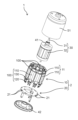
- FIG. 3 is an exploded perspective view of the electric motor according to the embodiment, viewed diagonally from above.
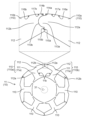
- FIG. 4 is a plan view of the stator core according to the embodiment when a plurality of core blocks are connected in a first connection pattern.
- FIG. 5 is a plan view of a core block that constitutes the stator core according to the embodiment.
- FIG. 6 is a plan view of the stator core according to the embodiment when a plurality of core blocks are connected in a second connection pattern.
- FIG. 1 is a cross-sectional view of the electric motor 1 according to the embodiment taken along a plane passing through the rotating shaft 31.
- FIG. 2 is a cross-sectional view of the electric motor 1 according to the embodiment taken along a plane perpendicular to the rotating shaft 31.
- FIG. FIG. 2 shows a cross section taken along line II-II in FIG.
- FIG. 3 is an exploded perspective view of the electric motor 1 according to the embodiment, viewed diagonally from above.
- the electric motor 1 includes a stator 10, a circuit board 20, and a rotor 30 having a rotating shaft 31.
- Stator 10 and circuit board 20 are combined as stator assembly 2.
- the electric motor 1 further includes a first bearing 41, a second bearing 42, a first bracket 51, and a second bracket 52.
- the electric motor 1 is a brushless motor.
- the electric motor 1 can be used, for example, as a blower motor or a drive motor that is small and requires high output.
- the size of the electric motor 1 is, for example, a diameter of 50 mm or less. Specifically, the size of the electric motor 1 is, for example, 20 mm or 30 mm in diameter.
- the electric motor 1 is an inner rotor type motor in which a rotor 30 is disposed inside a stator 10. That is, the stator 10 is arranged so as to surround the rotor 30. Therefore, the rotor 30 rotates around the axis C of the rotating shaft 31 inside the stator 10.
- a stator (stator) 10 is disposed facing the rotor 30 with a small air gap therebetween. Specifically, the stator 10 is arranged so as to surround the rotor core 32 of the rotor 30.
- the stator 10 generates magnetic force that acts on the rotor 30.
- the stator 10 has a configuration in which a plurality of N poles and S poles are alternately and repeatedly present along the rotation direction so as to generate magnetic flux in the air gap surface between the rotor core 32 and the rotor 30. ing.
- the stator 10 and the rotor 30 constitute a magnetic circuit.
- the stator 10 constitutes an armature.
- the stator 10 includes a stator core 11 (stator core) and a winding 12 arranged on the stator core 11.
- the winding 12 is a winding coil wound around the stator core 11.
- the stator core 11 has a plurality of teeth 11a that protrude toward the rotor 30. Specifically, the plurality of teeth 11a extend radially in a direction (radial direction) orthogonal to the axis C of the rotating shaft 31. The plurality of teeth 11a are arranged at equal intervals in the circumferential direction while forming slots 11b between two adjacent teeth 11a. Stator core 11 has nine teeth 11a. In other words, the number of slots in the stator 10 is nine.
- Winding 12 is arranged in the slot 11b of the stator core 11.
- Winding 12 is a stator coil that is an armature winding of stator 10 .
- the winding 12 is a concentrated winding coil wound around each tooth 11a.
- the winding 12 is a three-phase winding so that the rotor 30 can be rotated as a three-phase synchronous motor.
- the winding 12 is composed of unit coils for each of three phases, U-phase, V-phase, and W-phase, which are electrically different in phase by 120 degrees from each other. That is, the winding 12 wound around each tooth 11a is energized and driven by three-phase alternating current that is energized in units of U phase, V phase, and W phase. Thereby, the main magnetic flux of the stator 10 is generated in each tooth 11a.
- each tooth 11a is a magnetic pole tooth.
- Each tooth 11a is an electromagnet that generates magnetic force when current flows through the winding 12.
- the stator core 11 is divided into a plurality of core blocks 110 (divided cores). That is, the stator core 11 of the stator 10 is composed of a plurality of core blocks 110.
- the plurality of core blocks 110 are arranged in an annular shape as a whole. Specifically, nine core blocks 110 are arranged in an annular shape. Two adjacent core blocks 110 are connected to each other. That is, the stator core 11 is configured by connecting a plurality of core blocks in an annular shape. A winding 12 is wound around each of the plurality of core blocks 110. Since stator 10 has nine core blocks 110, nine windings 12 are used.
- an intermediate assembly 100 is composed of one core block 110 and one winding 12.
- Intermediate assembly 100 is an intermediate part used when manufacturing stator assembly 2.
- the stator 10 is constructed by combining a plurality of intermediate assemblies 100. Specifically, the stator 10 is configured by arranging a plurality of intermediate assemblies 100 in a cylindrical shape. The plurality of intermediate assemblies 100 are combined by connecting the core blocks 110 in an annular shape.
- the stator 10 is composed of nine intermediate assemblies 100.
- each of the plurality of intermediate assemblies 100 includes a core block 110, a winding 12, a connecting terminal 120, and an insulator 130.
- the winding 12 is wound around the core block 110 via an insulator 130.
- the connection terminal 120 is fixed to the insulator 130. The detailed configuration of the core block 110 will be described later.
- the circuit board 20 is, for example, a printed circuit board (PCB) on which wiring made of a conductive material such as copper is formed in a predetermined pattern.
- PCB printed circuit board
- a resin material such as a glass epoxy substrate, a metal material such as an aluminum alloy substrate, or the like can be used.
- a plurality of electronic components (not shown) for generating a current to be supplied to the winding 12 of the stator 10 are mounted on the circuit board 20.
- the plurality of electronic components constitute a circuit that generates three-phase alternating current of U phase, V phase, and W phase.
- a through hole 21 is provided in the circuit board 20.
- the connection terminal 120 of the intermediate assembly 100 corresponding to the core block 110 is connected to the through hole 21.
- the connection terminal 120 is a connection terminal to which the winding 12 of the stator 10 is connected.
- the connection terminal 120 has a connection pin, and the connection pin of the connection terminal 120 to which the winding 12 is connected is inserted into the through hole 21 .
- the connection terminal 120 and the circuit board 20 are connected.
- the circuit board 20 is a wiring board to which the windings 12 are connected via the connection terminals 120.
- the circuit board 20 is provided with a plurality of through holes 21 .
- connection pins of the connection terminals 120 are press-fitted into the through holes 21 of the circuit board 20. Thereby, the connection terminal 120 can be fixed to the circuit board 20.
- the inner peripheral surface of each through hole 21 is coated with a conductive film (for example, copper plating) that is electrically connected to wiring formed on the main surface of the circuit board 20 . Therefore, by press-fitting the connection pin of the connection terminal 120 into the through hole 21, the connection terminal 120 is mechanically connected to the circuit board 20. Further, it is electrically connected to the wiring of the circuit board 20 via a conductive film coated on the inner peripheral surface of the through hole 21 .
- the rotor (rotor) 30 is rotated by the magnetic force generated by the stator 10.
- the rotor 30 has a structure in which a plurality of north poles and south poles are alternately and repeatedly present along the rotation direction. Thereby, the rotor 30 generates a magnetic force that acts on the stator 10.
- the direction of the magnetic flux generated by the rotor 30 is a direction perpendicular to the direction in which the axis C included in the rotating shaft 31 extends (axial direction). That is, the direction of the magnetic flux generated by the rotor 30 is the radial direction.
- the rotor 30 includes a rotating shaft 31, a rotor core 32, and a permanent magnet 33.
- the rotor 30 is an interior permanent magnet (IPM) rotor in which a permanent magnet 33 is embedded in a rotor core 32. Therefore, electric motor 1 is an IPM motor.
- the rotating shaft 31 is an elongated shaft.
- the rotating shaft 31 is, for example, a metal rod.
- the rotating shaft 31 is fixed to a rotor core 32. Specifically, the rotating shaft 31 is inserted into a through hole provided at the center of the rotor core 32 and fixed to the rotor core 32 so as to extend on both sides of the rotor core 32 in the direction in which the axis C extends. There is.
- the rotor core 32 is a laminate in which a plurality of steel plates are laminated along the direction in which the axis C of the rotating shaft 31 extends (axial direction).
- Each of the plurality of steel plates is, for example, a punched electromagnetic steel plate formed into a predetermined shape.
- the plurality of steel plates are fixed to each other, for example, by caulking.
- the permanent magnet 33 is inserted into a magnet insertion hole 32a provided in the rotor core 32.
- Six magnet insertion holes 32a are provided in the rotor core 32 at equal intervals in the circumferential direction. Therefore, the rotor 30 has six permanent magnets 33 arranged at equal intervals in the circumferential direction. That is, the number of poles of the electric motor 1 is six.
- Permanent magnet 33 is a sintered magnet. However, the permanent magnet 33 may be a bonded magnet.
- the rotating shaft 31 of the rotor 30 is provided with a first bearing 41 and a second bearing 42 that rotatably hold the rotating shaft 31.
- the first bearing 41 and the second bearing 42 are bearings that rotatably hold the rotating shaft 31.
- the first bearing 41 supports a portion of the rotating shaft 31 that protrudes from one side of the rotor core 32 .
- the second bearing 42 supports a portion of the rotating shaft 31 that protrudes from the other side of the rotor core 32.
- the first bearing 41 and the second bearing 42 are, for example, ball bearings. However, it is not limited to this.
- the first bracket 51 holds the first bearing 41. Specifically, the first bearing 41 is fixed to a recess provided in the first bracket 51.
- the second bracket 52 holds the second bearing 42. Specifically, the second bearing 42 is fixed to a recess provided in the second bracket 52.
- the first bracket 51 and the second bracket 52 are made of metal or resin material.
- the first bracket 51 and the second bracket 52 constitute the outer shell of the electric motor 1.
- the first bracket 51 is a bottomed cylindrical frame (housing) having an opening.
- the second bracket 52 is a bottom plate that closes the opening of the first bracket 51.
- the first bracket 51 is a metal frame made of metal.
- the second bracket 52 is a resin plate made of resin.
- the rotating shaft 31 of the rotor 30 passes through the first bracket 51. A portion of the rotating shaft 31 protrudes from the first bracket 51 to the outside. Although not shown, a load such as a rotating fan is attached to a portion of the rotating shaft 31 that protrudes from the first bracket 51 to the outside. That is, the portion of the rotating shaft 31 that protrudes from the first bracket 51 is an output shaft.
- stator 10 stator core 11
- magnetic flux directed from the stator 10 to the rotor 30 is generated.
- magnetic flux is generated from each of the teeth 11a of the stator core 11 of the stator 10 toward the rotor core 32 of the rotor 30.
- a magnetic flux passing through the stator 10 is generated by the permanent magnet 33 embedded in the rotor core 32.
- the magnetic force generated by the interaction between the magnetic flux generated by the stator 10 and the magnetic flux generated from the permanent magnets 33 of the rotor 30 becomes a torque that rotates the rotor 30. This causes the rotor 30 to rotate.
- FIG. 4 is a plan view of the stator core 11 according to the embodiment when a plurality of core blocks 110 are connected in a first connection pattern.
- FIG. 5 is a plan view of a core block 110 that constitutes the stator core 11 according to the embodiment.
- Each of the plurality of core blocks 110 is constructed by laminating a plurality of steel plates.
- each core block 110 is a laminate in which a plurality of punched electromagnetic steel sheets are laminated along the direction in which the axis C of the rotating shaft 31 extends.
- Each electromagnetic steel sheet that constitutes the core block 110 has the same shape.
- Each of the plurality of electromagnetic steel plates is fixed to each other, for example, by caulking.
- each core block 110 has teeth portions 111 and yoke portions 112.
- Teeth portion 111 is teeth 11a of stator core 11 shown in FIG.
- the teeth portion 111 is formed inside the yoke portion 112. Teeth portion 111 extends from yoke portion 112 toward the center of stator core 11 . Specifically, the teeth portion 111 extends from the yoke portion 112 toward the rotating shaft 31. That is, the teeth portion 111 extends so as to protrude inward in the radial direction of the stator 10.
- the tooth portion 111 has an extending portion 111a that extends from the inner peripheral end of the tooth portion 111 to both sides in the circumferential direction. Each of the pair of extending portions 111a is formed to protrude from the tip portion of the tooth portion 111 on the inner circumferential side along the circumferential direction. In two adjacent core blocks 110, a gap (slot opening) 111b is formed between the extending portion 111a of the tooth portion 111 in one core block 110 and the extending portion 111a of the tooth portion 111 in the other core block 110.
- a gap (slot opening) 111b is formed between the extending portion 111a of the tooth portion 111 in one core block 110 and the extending portion 111a of the tooth portion 111 in the other core block 110.
- a slot 11b for arranging the winding 12 is formed between two adjacent teeth portions 111.
- the slot 11b is a space area on the side of the teeth portion 111.
- the winding 12 is wound around the teeth 111. Specifically, the winding 12 is wound around the teeth 111 via an insulator 130.
- the yoke portion 112 is a back yoke formed on the outside of the teeth portion 111.
- Yoke portion 112 extends along the circumferential direction of stator core 11 .
- the yoke portion 112 extends along the circumferential direction (rotation direction of the rotary shaft 31) centering on the axis C of the rotary shaft 31.
- two adjacent yoke portions 112 are connected with their circumferential end surfaces abutting each other.
- nine yoke parts 112 are arranged along the circumferential direction of a circle centered on the axis C of the rotating shaft 31, and are connected to form an annular shape as a whole. There is.
- a first end 112a which is one end in the circumferential direction of the yoke portion 112, has a convex portion 113a and a first end portion 112a located on both sides of the convex portion 113a.
- a surface 114a and a second surface 115a are provided.
- the convex portion 113a, the first surface 114a, and the second surface 115a are formed on the end surface facing the circumferential direction of the first end portion 112a.
- the convex portion 113a is sandwiched between the first surface 114a and the second surface 115a.
- the convex portion 113a is formed to protrude from the first end portion 112a toward the circumferential direction of the stator core 11.
- the convex portion 113a has a semicircular shape when viewed from above. Therefore, when the core block 110 is viewed stereoscopically, the convex portion 113a has a semi-cylindrical shape.
- the top view shape of the convex portion 113a is not limited to a semicircle.
- the first surface 114a is located on the outer peripheral side of the convex portion 113a. Specifically, the first surface 114a is a plane parallel to a plane passing through the axis C of the rotating shaft 31. The first surface 114a extends toward the outer circumferential side from the root on the outer circumferential side of the convex portion 113a. The first surface 114a is a flat surface.
- the second surface 115a is located on the inner peripheral side of the convex portion 113a. Specifically, the second surface 115a is a plane parallel to a plane passing through the axis C of the rotating shaft 31. The second surface 115a extends toward the inner circumferential side from the root on the inner circumferential side of the convex portion 113a. The second surface 115a is a flat surface.
- the first surface 114a and the second surface 115a are both surfaces facing in the circumferential direction of the rotating shaft 31. Regarding the first surface 114a and the second surface 115a, the angle of inclination of the first surface 114a with respect to the radial direction of the rotating shaft 31 is different from the angle of inclination of the second surface 115a with respect to the radial direction of the rotating shaft 31. As shown in FIG. 5, when the core block 110 is viewed from above, the intersection of the first straight line L1 when the first surface 114a is extended and the second straight line L2 when the second surface 115a is extended is a convex It is located within the section 113a.
- the second end 112b which is the other end in the circumferential direction of the yoke part 112, has a recess 113b that can fit into the convex part 113a, and a third surface 114b and a fourth surface located on both sides of the recess 113b.
- a surface 115b is provided.
- the recess 113b, the third surface 114b, and the fourth surface 115b are formed on the end surface facing the circumferential direction of the second end 112b.
- the recess 113b is sandwiched between the third surface 114b and the fourth surface 115b.
- the recess 113b is formed to be depressed in the circumferential direction of the stator core 11 from the second end 112b.
- the shape of the recess 113b when viewed from above is semicircular. In other words, the surface of the recess 113b when viewed from above is an arc. Therefore, when the core block 110 is viewed stereoscopically, the recess 113b has a shape in which the second end 112b is recessed into a semi-cylindrical shape.
- the shape of the recess 113b is not limited to this.
- the shape of the concave portion 113b may be any shape as long as it can fit into the convex portion 113a.
- the third surface 114b is located on the outer peripheral side of the recess 113b. Specifically, the third surface 114b is a plane parallel to a plane passing through the axis C of the rotating shaft 31. The third surface 114b extends from the root on the outer circumferential side of the recess 113b toward the outer circumferential side. The third surface 114b is a flat surface.
- the third surface 114b is a surface that can make surface contact with the first surface 114a at the first end 112a of the yoke portion 112. Therefore, the first surface 114a of the first end 112a of the yoke portion 112 is a surface that can make surface contact with the third surface 114b.
- the fourth surface 115b is located on the inner peripheral side of the recess 113b. Specifically, the fourth surface 115b is a plane parallel to a plane passing through the axis C of the rotating shaft 31. The fourth surface 115b extends toward the inner circumferential side from the root on the inner circumferential side of the recessed portion 113b. The fourth surface 115b is a flat surface.
- the fourth surface 115b is a surface that can make surface contact with the second surface 115a at the first end 112a of the yoke portion 112. Therefore, the second surface 115a of the first end 112a of the yoke portion 112 is a surface that can make surface contact with the fourth surface 115b.
- the third surface 114b and the fourth surface 115b are both surfaces facing in the circumferential direction of the rotating shaft 31. Regarding the third surface 114b and the fourth surface 115b, the angle of inclination of the third surface 114b with respect to the radial direction of the rotating shaft 31 is different from the angle of inclination of the fourth surface 115b with respect to the radial direction of the rotating shaft 31. As shown in FIG. 5, when the core block 110 is viewed from above, the intersection of the third straight line L3 when the third surface 114b is extended and the fourth straight line L4 when the fourth surface 115b is extended is located at the recess. 113b.
- the circumscribed surface of the yoke portion 112 includes two curved surfaces (R surfaces) with different radii of curvature.
- the outline of the yoke portion 112 in the core block 110 includes a plurality of circular arcs with different radii of curvature.
- the outline of one side of the yoke part 112 in the circumferential direction with the teeth part 111 as a reference includes a first circular arc 116a and a second circular arc 117a having mutually different radii of curvature.
- the radius of curvature R2 of the second circular arc 117a is larger than the radius of curvature R1 of the first circular arc 116a (R2>R1).
- the second circular arc 117a is located closer to the tip of the yoke portion 112 than the first circular arc 116a.
- the arc length of the second circular arc 117a is shorter than the arc length of the first circular arc 116a.
- the first circular arc 116a and the second circular arc 117a are continuous.
- the outline of the other circumferential side of the yoke portion 112 with respect to the teeth portion 111 includes a third circular arc 116b and a fourth circular arc 117b having mutually different radii of curvature.
- the radius of curvature R4 of the fourth arc 117b is larger than the radius of curvature R3 of the third arc 116b (R4>R3).
- the fourth arc 117b is located closer to the tip of the yoke portion 112 than the third arc 116b.
- the length of the fourth arc 117b is shorter than the length of the third arc 116b.
- the third circular arc 116b and the fourth circular arc 117b are continuous.
- a plurality of core blocks 110 configured in this manner are arranged and connected in an annular shape.
- the plurality of core blocks 110 arranged in an annular shape are connected by connecting the yoke portions 112 of two adjacent core blocks 110 to each other.
- the plurality of core blocks 110 all have the same shape. That is, the stator core 11 is composed only of the core block 110 having the shape shown in FIG.
- connection portion of the second core block 110b with the yoke portion 112 includes a convex portion 113a, a first surface 114a located on the outer circumferential side of the convex portion 113a, and a second surface 115a located on the inner circumferential side of the convex portion 113a. and is provided.
- a first end 112a of the yoke portion 112 of the first core block 110a on the second core block 110b side is provided with a convex portion 113a, a first surface 114a, and a second surface 115a.
- the connecting portion of the yoke portion 112 of the second core block 110b with the yoke portion 112 of the first core block 110a includes a recess 113b, a third surface 114b located on the outer peripheral side of the recess 113b, and a third surface 114b located on the inner peripheral side of the recess 113b.
- a fourth surface 115b located at is provided. That is, the second end 112b of the yoke portion 112 of the second core block 110b on the first core block 110a side is provided with a recess 113b, a third surface 114b, and a fourth surface 115b.
- a convex portion 113a in the yoke portion 112 of the first core block 110a and a concave portion 113b in the yoke portion 112 of the second core block 110b fit together.
- the stator core 11 is composed of a plurality of core blocks 110 including a first core block 110a and a second core block 110b.
- the stator core 11 shown in FIG. 4 nine core blocks 110 are connected. That is, the number of slots in the stator 10 having the stator core 11 shown in FIG. 4 is nine.
- the first surface 114a of the yoke portion 112 of the first core block 110a and the second core block 110b The third surface 114b of the yoke portion 112 is in surface contact with the third surface 114b. That is, in FIG. 4, the first surface 114a becomes a contact surface that contacts the third surface 114b.
- the third surface 114b becomes a contact surface that contacts the first surface 114a. Therefore, when the core blocks 110 are connected as shown in FIG. 4, the first surface 114a and the third surface 114b become the mating surfaces of the core blocks 110.
- the second surface 115a of the yoke portion 112 of the first core block 110a and the fourth surface 115b of the yoke portion 112 of the second core block 110b are not in contact. That is, a gap exists between the second surface 115a and the fourth surface 115b. The second surface 115a and the fourth surface 115b are separated. Therefore, when the core blocks 110 are connected as shown in FIG. 4, the second surface 115a and the fourth surface 115b become non-contact surfaces.
- the number of slots in the stator 10 having the stator core 11 is nine.
- the first surface 114a of the first core block 110a and the third surface 114b of the second core block 110b are in surface contact
- the first The circular arc 116a and the third circular arc 116b on the outline of the yoke portion 112 of the second core block 110b are the same circular arc.
- the diameter of the circle formed by the first circular arc 116a and the third circular arc 116b is 50 mm or less.
- the contact surface becomes The first surface 114a and the third surface 114b coincide with the radial direction of the rotating shaft 31 when viewed from above.
- the convex part 113a of the first core block 110a and the concave part 113b of the second core block 110b are fitted together, and the first surface 114a of the first core block 110a and the Nine core blocks 110 can be connected by bringing the two core blocks 110b into surface contact with the third surface 114b. That is, by manufacturing the stator core 11 by connecting nine core blocks 110, a stator 10 having nine slots can be obtained.
- FIG. 6 is a plan view of the stator core 11 according to the embodiment when a plurality of core blocks 110 are connected in the second connection pattern.
- the core block 110 as shown in FIG. 6, the convex part 113a of the first core block 110a and the concave part 113b of the second core block 110b are fitted together, and the second surface 115a of the first core block 110a and the second By making surface contact with the fourth surface 115b of the core block 110b, six core blocks 110 can be connected. That is, by manufacturing the stator core 11 by connecting six core blocks 110, a stator 10 having six slots can be obtained.
- the second surface 115a of the first core block 110a and The fourth surface 115b of the second core block 110b becomes a contact surface. That is, in FIG. 6, the second surface 115a becomes a contact surface that contacts the fourth surface 115b. The fourth surface 115b becomes a contact surface that contacts the second surface 115a. Therefore, when the core blocks 110 are connected as shown in FIG. 6, the second surface 115a and the fourth surface 115b become the mating surfaces of the core blocks 110.
- the first surface 114a of the yoke portion 112 of the first core block 110a and the third surface 114b of the yoke portion 112 of the second core block 110b are not in contact. That is, a gap exists between the first surface 114a and the third surface 114b.
- the first surface 114a and the third surface 114b are separated. That is, in FIG. 6, the first surface 114a and the third surface 114b are non-contact surfaces.
- the The arc 117a and the fourth arc 117b in the outline of the yoke portion 112 of the second core block 110b are arcs of the same circle. Also in this case, the diameter of the circle formed by the second circular arc 117a and the fourth circular arc 117b is 50 mm or less.
- the diameter of the stator core 11 in the case of the second connection pattern shown in FIG. 6 is smaller than the diameter of the stator core 11 in the case of the first connection pattern shown in FIG.
- the contact surface becomes The second surface 115a and the fourth surface 115b coincide with the radial direction of the rotating shaft 31 when viewed from above.
- the core block 110 includes the teeth portions 111 and the yoke portions 112.
- the circumferential first end 112a of the yoke portion 112 includes a convex portion 113a, a first surface 114a located on the outer circumferential side of the convex portion 113a, and a second surface 115a located on the inner circumferential side of the convex portion 113a. is provided.
- the second end 112b in the circumferential direction of the yoke portion 112 includes a recess 113b that can fit into the convex portion 113a, a third surface 114b located on the outer peripheral side of the recess 113b, and a third surface 114b located on the inner peripheral side of the recess 113b.
- a fourth surface 115b is provided.
- first core blocks 110a and second core blocks 110b among the plurality of core blocks 110 are arranged as shown in FIG.
- the first surface 114a and the third surface 114b are connected by surface contact, or as shown in FIG. 6, the second surface 115a and the fourth surface 115b are connected by surface contact.
- the plurality of core blocks 110 are connected by a first connection pattern in which the first surface 114a and the third surface 114b are brought into surface contact, or as shown in FIG.
- the plurality of core blocks 110 are connected by a second connection pattern in which the fourth surface 115a and the fourth surface 115b are brought into surface contact.
- the number of slots is different depending on the case where the first surface 114a and the third surface 114b are in surface contact and the case where the second surface 115a and the fourth surface 115b are in surface contact.
- the number of slots is nine when the first surface 114a and the third surface 114b are brought into surface contact.
- the number of slots is six when the second surface 115a and the fourth surface 115b are brought into surface contact.
- one core block 110 can be used in two ways.
- the outline of the yoke portion 112 in the first core block 110a includes a first circular arc 116a and a second circular arc 117a having mutually different radii of curvature.
- the outline of the yoke portion 112 in the second core block 110b includes a third circular arc 116b and a fourth circular arc 117b having mutually different radii of curvature.
- the second surface 115a and the fourth surface 115b on the inner circumferential side come into surface contact, as shown in FIG.
- the outer surface of the stator core 11 comes into contact with the inner surface of the first bracket 51 (frame), as shown in FIG. Therefore, if a corner is formed on the outer surface of the stator core 11, this corner will come into contact with the inner surface of the first bracket 51. Therefore, stress from the first bracket 51 is applied to the stator core 11. As a result, the stator core 11 may be damaged or the position of the stator core 11 may shift, making it impossible to generate the desired magnetic flux.
- the first core block 110a and the second It is possible to suppress the connection portion with the core block 110b from becoming angular.
- FIG. 6 when the first core block 110a and the second core block 110b are connected so that the second surface 115a and the fourth surface 115b on the inner peripheral side are in surface contact, It is possible to prevent the connecting portion between the first core block 110a and the second core block 110b from becoming angular. Thereby, the stress load applied to the stator core 11 can be alleviated.
- the electric motor 1 of the present embodiment includes a stator 10 having a stator core 11 in which a plurality of core blocks 110 are connected in an annular shape, and a rotor having a rotating shaft 31 and disposed inside the stator 10. 30.
- the plurality of core blocks 110 include a first core block 110a and a second core block 110b that are connected.
- Each of the first core block 110a and the second core block 110b includes a yoke portion 112 extending along the circumferential direction centered on the axis of the rotating shaft 31, and teeth extending from the yoke portion 112 toward the rotating shaft 31. 111.
- the connecting portion of the yoke portion 112 of the first core block 110a with the yoke portion 112 of the second core block 110b includes a convex portion 113a, a first surface 114a located on the outer peripheral side of the convex portion 113a, and a first surface 114a of the convex portion 113a.
- a second surface 115a located on the inner peripheral side is provided.
- the connecting portion of the yoke portion 112 of the second core block 110b with the yoke portion 112 of the first core block 110a includes a recess 113b that fits into the convex portion 113a, a third surface 114b located on the outer peripheral side of the recess 113b, and a recess.
- a fourth surface 115b located on the inner peripheral side of 113b is provided.
- the first core block 110a and the second core block 110b are connected by the surface contact between the first surface 114a and the third surface 114b, or the surface contact between the second surface 115a and the fourth surface 115b. It is connected by doing.
- the core block 110 of this embodiment is a core block 110 that constitutes the stator core 11 by being connected in a plurality of annular shapes, and includes a yoke portion 112 extending along the circumferential direction of the stator core 11 and a
- the stator core 11 has teeth portions 111 extending toward the center of the stator core 11 .
- One circumferential end of the yoke 112 includes a convex portion 113a, a first surface 114a located on the outer circumferential side of the convex portion 113a, and a second surface 115a located on the inner circumferential side of the convex portion 113a. It is provided.
- the other end of the yoke portion 112 in the circumferential direction includes a recess 113b that can fit into the convex portion 113a, and a third surface that is located on the outer peripheral side of the recess 113b and that is in surface contact with the first surface 114a. 114b, and a fourth surface 115b that is located on the inner peripheral side of the recess 113b and is in surface contact with the second surface 115a.
- the electric motor 1 of this embodiment includes a stator 10 having a stator core 11 and a winding wound around the stator core 11, and a rotor 30 located opposite the stator 10.
- the core block 110 has nine slots when the first surface 114a and the third surface 114b are in surface contact, and the number of slots is 9 when the second surface 115a and the fourth surface 115b are in surface contact.
- the shape is such that the number of slots is 6 when the number of slots is 6.
- the core block 110 has 12 slots when the first surface 114a and the third surface 114b are in surface contact, and the number of slots is 12 when the second surface 115a and the fourth surface 115b are in surface contact.
- the shape may be such that the number of slots is nine.
- the rotor 30 is an IPM rotor.
- the rotor 30 may be a surface permanent magnetic rotor (SPM (Surface Permanent Magnetic) rotor) in which a plurality of permanent magnets are provided on the outer surface of a rotor core.
- SPM Surface Permanent Magnetic
- the rotor 30 is a laminate in which a plurality of steel plates are laminated. However, it is not limited to this.
- the rotor 30 may be made of bulk material.
- the technology of the present disclosure can be widely used in electric motors, electrical equipment equipped with electric motors, and the like.
Landscapes
- Engineering & Computer Science (AREA)
- Power Engineering (AREA)
- Manufacturing & Machinery (AREA)
- Iron Core Of Rotating Electric Machines (AREA)
Priority Applications (3)
| Application Number | Priority Date | Filing Date | Title |
|---|---|---|---|
| CN202380041015.XA CN119234370A (zh) | 2022-05-27 | 2023-04-03 | 电动机、芯块和定子芯 |
| EP23811461.5A EP4535615A4 (en) | 2022-05-27 | 2023-04-03 | ELECTRIC MOTOR, CORE BLOCK, AND STATOR CORE |
| JP2024522956A JPWO2023228582A1 (https=) | 2022-05-27 | 2023-04-03 |
Applications Claiming Priority (2)
| Application Number | Priority Date | Filing Date | Title |
|---|---|---|---|
| JP2022-087077 | 2022-05-27 | ||
| JP2022087077 | 2022-05-27 |
Publications (1)
| Publication Number | Publication Date |
|---|---|
| WO2023228582A1 true WO2023228582A1 (ja) | 2023-11-30 |
Family
ID=88919054
Family Applications (1)
| Application Number | Title | Priority Date | Filing Date |
|---|---|---|---|
| PCT/JP2023/013765 Ceased WO2023228582A1 (ja) | 2022-05-27 | 2023-04-03 | 電動機、コアブロック及びステータコア |
Country Status (4)
| Country | Link |
|---|---|
| EP (1) | EP4535615A4 (https=) |
| JP (1) | JPWO2023228582A1 (https=) |
| CN (1) | CN119234370A (https=) |
| WO (1) | WO2023228582A1 (https=) |
Citations (6)
| Publication number | Priority date | Publication date | Assignee | Title |
|---|---|---|---|---|
| JP2000069717A (ja) * | 1998-08-21 | 2000-03-03 | Matsushita Electric Ind Co Ltd | 電動機 |
| JP2003092863A (ja) * | 2001-09-20 | 2003-03-28 | Nissan Motor Co Ltd | 永久磁石埋込同期モータ |
| JP2006340509A (ja) * | 2005-06-02 | 2006-12-14 | Mitsuba Corp | 電動機の固定子及び電動機 |
| JP2010119163A (ja) * | 2008-11-11 | 2010-05-27 | Mitsubishi Electric Corp | 圧縮機、圧縮機の組立設備、及び、圧縮機の組立方法 |
| JP2010259174A (ja) | 2009-04-23 | 2010-11-11 | Harmonic Drive Syst Ind Co Ltd | モータステータの製造方法 |
| WO2012114428A1 (ja) * | 2011-02-21 | 2012-08-30 | 三菱電機株式会社 | 回転電機のユニットコア |
Family Cites Families (1)
| Publication number | Priority date | Publication date | Assignee | Title |
|---|---|---|---|---|
| JP3568364B2 (ja) * | 1996-09-30 | 2004-09-22 | 松下電器産業株式会社 | 回転電機のコア |
-
2023
- 2023-04-03 EP EP23811461.5A patent/EP4535615A4/en active Pending
- 2023-04-03 CN CN202380041015.XA patent/CN119234370A/zh active Pending
- 2023-04-03 JP JP2024522956A patent/JPWO2023228582A1/ja active Pending
- 2023-04-03 WO PCT/JP2023/013765 patent/WO2023228582A1/ja not_active Ceased
Patent Citations (6)
| Publication number | Priority date | Publication date | Assignee | Title |
|---|---|---|---|---|
| JP2000069717A (ja) * | 1998-08-21 | 2000-03-03 | Matsushita Electric Ind Co Ltd | 電動機 |
| JP2003092863A (ja) * | 2001-09-20 | 2003-03-28 | Nissan Motor Co Ltd | 永久磁石埋込同期モータ |
| JP2006340509A (ja) * | 2005-06-02 | 2006-12-14 | Mitsuba Corp | 電動機の固定子及び電動機 |
| JP2010119163A (ja) * | 2008-11-11 | 2010-05-27 | Mitsubishi Electric Corp | 圧縮機、圧縮機の組立設備、及び、圧縮機の組立方法 |
| JP2010259174A (ja) | 2009-04-23 | 2010-11-11 | Harmonic Drive Syst Ind Co Ltd | モータステータの製造方法 |
| WO2012114428A1 (ja) * | 2011-02-21 | 2012-08-30 | 三菱電機株式会社 | 回転電機のユニットコア |
Non-Patent Citations (1)
| Title |
|---|
| See also references of EP4535615A4 |
Also Published As
| Publication number | Publication date |
|---|---|
| EP4535615A4 (en) | 2025-09-03 |
| JPWO2023228582A1 (https=) | 2023-11-30 |
| EP4535615A1 (en) | 2025-04-09 |
| CN119234370A (zh) | 2024-12-31 |
Similar Documents
| Publication | Publication Date | Title |
|---|---|---|
| JP3146492B2 (ja) | ブラシレスdcモータ | |
| US20170201135A1 (en) | Stator and rotary machine | |
| JP5117813B2 (ja) | 回転電機 | |
| KR20180054087A (ko) | 스테이터 일체형 차량용 팬모터 | |
| CN101253668A (zh) | 包含带有倾斜齿的扁平定子的电机 | |
| JP5277743B2 (ja) | 回転電機 | |
| JP5595135B2 (ja) | 2相ハイブリッド型回転電機 | |
| JP6226654B2 (ja) | 回転電機及びそれを備えた空調機器 | |
| CN110462978A (zh) | 电动马达用定子和电动马达 | |
| KR100213571B1 (ko) | 일체형 스테이터를 이용한 더블로터/단일스테이터방식의 코어레스형 비엘디씨 모터 | |
| EP3324518B1 (en) | Armature, dynamo-electric machine, crossflow fan | |
| JP2023054419A (ja) | 回転電機 | |
| WO2023228582A1 (ja) | 電動機、コアブロック及びステータコア | |
| US20220181933A1 (en) | Rotor, motor, and electric power steering device | |
| JP4482918B2 (ja) | リング状の固定子コイルを有する永久磁石型電動機 | |
| JP7745135B2 (ja) | 積層鉄心それを備える電動機 | |
| US12176754B2 (en) | Electric machine and magnetic field portion | |
| CN108886304A (zh) | 电动马达用定子的制造方法、电动马达的制造方法、电动马达用定子以及电动马达 | |
| JP2015027175A (ja) | 回転電機及び回転電機の製造方法 | |
| CN102804551A (zh) | 定子和旋转电机 | |
| JP2006087190A (ja) | 非円筒形状のギャップを有するモータ | |
| JP4794555B2 (ja) | ステッピングモータ | |
| JP7543229B2 (ja) | アキシャルギャップ型回転電機のステータコア、アキシャルギャップ型回転電機のステータ製造方法 | |
| WO2018180343A1 (ja) | 電動モータ用ステータおよび電動モータ | |
| WO2024219120A1 (ja) | ステータ、電動機及びステータの製造方法 |
Legal Events
| Date | Code | Title | Description |
|---|---|---|---|
| 121 | Ep: the epo has been informed by wipo that ep was designated in this application |
Ref document number: 23811461 Country of ref document: EP Kind code of ref document: A1 |
|
| WWE | Wipo information: entry into national phase |
Ref document number: 2024522956 Country of ref document: JP |
|
| WWE | Wipo information: entry into national phase |
Ref document number: 202380041015.X Country of ref document: CN |
|
| NENP | Non-entry into the national phase |
Ref country code: DE |
|
| WWP | Wipo information: published in national office |
Ref document number: 202380041015.X Country of ref document: CN |
|
| WWE | Wipo information: entry into national phase |
Ref document number: 2023811461 Country of ref document: EP |
|
| ENP | Entry into the national phase |
Ref document number: 2023811461 Country of ref document: EP Effective date: 20250102 |
|
| WWP | Wipo information: published in national office |
Ref document number: 2023811461 Country of ref document: EP |