WO2023228424A1 - コントローラ装置 - Google Patents
コントローラ装置 Download PDFInfo
- Publication number
- WO2023228424A1 WO2023228424A1 PCT/JP2022/021817 JP2022021817W WO2023228424A1 WO 2023228424 A1 WO2023228424 A1 WO 2023228424A1 JP 2022021817 W JP2022021817 W JP 2022021817W WO 2023228424 A1 WO2023228424 A1 WO 2023228424A1
- Authority
- WO
- WIPO (PCT)
- Prior art keywords
- drive
- controller device
- guide
- tilting
- control unit
- Prior art date
Links
- 230000005540 biological transmission Effects 0.000 claims abstract description 26
- 230000010365 information processing Effects 0.000 description 35
- 238000001514 detection method Methods 0.000 description 6
- 238000010586 diagram Methods 0.000 description 5
- 230000033001 locomotion Effects 0.000 description 5
- NJPPVKZQTLUDBO-UHFFFAOYSA-N novaluron Chemical compound C1=C(Cl)C(OC(F)(F)C(OC(F)(F)F)F)=CC=C1NC(=O)NC(=O)C1=C(F)C=CC=C1F NJPPVKZQTLUDBO-UHFFFAOYSA-N 0.000 description 5
- 230000004044 response Effects 0.000 description 3
- 238000000034 method Methods 0.000 description 2
- 230000035807 sensation Effects 0.000 description 2
- 230000000903 blocking effect Effects 0.000 description 1
- 230000008685 targeting Effects 0.000 description 1
Images


Classifications
-
- G—PHYSICS
- G06—COMPUTING; CALCULATING OR COUNTING
- G06F—ELECTRIC DIGITAL DATA PROCESSING
- G06F3/00—Input arrangements for transferring data to be processed into a form capable of being handled by the computer; Output arrangements for transferring data from processing unit to output unit, e.g. interface arrangements
- G06F3/01—Input arrangements or combined input and output arrangements for interaction between user and computer
- G06F3/03—Arrangements for converting the position or the displacement of a member into a coded form
- G06F3/033—Pointing devices displaced or positioned by the user, e.g. mice, trackballs, pens or joysticks; Accessories therefor
- G06F3/0338—Pointing devices displaced or positioned by the user, e.g. mice, trackballs, pens or joysticks; Accessories therefor with detection of limited linear or angular displacement of an operating part of the device from a neutral position, e.g. isotonic or isometric joysticks
Definitions
- the present invention relates to a controller device that is connected to an information processing device and accepts user operations.
- Controller devices equipped with operating members that can be tilted are used as input devices for many information processing devices, such as home game machines.
- a controller device that controls the tilting angle and tilting direction of the operating member using an actuator to present a force sensation to the user of the controller device.
- the present invention has been made in view of the above-mentioned circumstances, and one of its objects is to provide a controller device that can reduce the uncomfortable feeling of operating an operating member when no external force is applied by an actuator.
- a controller device includes a tiltable operating member, a drive unit that generates power to control the tilting of the operating member, and a transmission unit that transmits or cuts off the power generated by the drive unit to the operating member. and a control unit that controls the transmission unit, the control unit controlling the transmission unit while the tilting direction or the tilting angle of the operating member satisfies at least a predetermined condition, The power generated by the drive section is not transmitted to the operating member.
- the controller device According to the controller device according to one aspect of the present invention, it is possible to reduce the uncomfortable feeling of operating the operating member in a state where no external force is applied by the actuator.
- FIG. 1 is a block diagram showing a schematic configuration of a controller device according to an embodiment of the present invention.
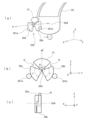
- FIG. 2 is an exploded perspective view showing an example of a tilting operation member included in the controller device according to the embodiment of the present invention.
- 1 is a schematic configuration diagram showing an example of a clutch member included in a controller device according to an embodiment of the present invention. It is an explanatory view showing an example of operation of a clutch member provided in a controller device according to an embodiment of the present invention. It is a schematic block diagram showing another example of the clutch member with which the controller device concerning an embodiment of the present invention is provided.
- FIG. 6 is an explanatory diagram showing another example of the operation of the clutch member included in the controller device according to the embodiment of the present invention. It is a schematic block diagram showing yet another example of the clutch member with which the controller device concerning embodiment of this invention is provided.
- a controller device 1 includes a control section 11, an operation section 12, a communication section 13, and a drive control section 14, as illustrated in FIG. Further, this controller device 1 is communicably connected to an information processing device 2.
- the information processing device 2 is a home game machine, a personal computer, etc., and receives information representing a user's operation performed on the controller device 1, and executes predetermined information processing such as game processing. . Further, in this embodiment, the information processing device 2 sends a control instruction for controlling the drive control unit 14 to the controller device 1 during the process of processing a game.
- the control unit 11 of the controller device 1 is a program control device such as a microcomputer equipped with a memory device, and operates according to a program stored in the memory device.
- the control unit 11 sends information representing the user's operation performed on the operation unit 12 to the information processing device 2 via the communication unit 13.
- the control unit 11 also controls the operations of the first actuator 23 and the second actuator 25 based on control instructions input from the information processing device 2 . The details of this control will be described later.
- the operation unit 12 includes a tilting operation member 121 such as a joystick that can be tilted.
- the operation section 12 may include other operation members such as a push button and a locking button.
- the operation unit 12 outputs information representing the contents of operations performed on these operation members to the control unit 11.
- the tilting operation member 121 outputs information on predetermined tilting angles in the X-axis and Y-axis directions that are orthogonal to each other to the control unit 11.
- the tilting operation member 121 may be able to be pushed in a direction perpendicular to both the X and Y axes (Z-axis direction), and in that case, information on the amount of pushing is also output to the control unit 11. That will happen.
- the tilting operation member 121 of this example includes a columnar body 21 to be tilted, a first guide 22, a first actuator 23, a second guide 24, and a second actuator, as shown in FIG. 25 and a pedestal 26.
- FIG. 2 is an exploded perspective view of the tilting operation member 121. Note that here, it is assumed that the first guide 22 and the second guide 24 are rotatably supported around the shafts 22A and 24A, respectively, within at least a predetermined angular range, and the direction of the shaft 22A is the X axis, and the direction of the shaft 24A is Let be the Y axis. Further, the direction perpendicular to both the X-axis and the Y-axis is defined as the Z-axis. That is, the first guide 22 rotates within the YZ plane around the axis 22A. Further, the second guide 24 rotates in the XZ plane around the axis 24A.
- the first guide 22 restricts the movement of the columnar body 21 in one direction (X-axis direction). As described above, the first guide 22 is rotatably supported within a predetermined angular range in the YZ plane around the axis 22A. Further, this angular range includes an angular range in which the columnar bodies 21 are parallel to the Z-axis direction.
- the first actuator 23 includes a motor 231 as a drive section, a sensor 232, and a clutch member 233 as a transmission section.
- the motor 231 is, for example, a three-phase brushless DC motor (having 3n (n is a natural number) stators), and current is applied to the stator coils of each phase according to instructions input from the drive control unit 14, which will be described later.
- the rotation direction, rotation speed, amount of rotation, etc. of the rotor are controlled by supplying it.
- the rotating shaft of the rotor of this motor 231 is connected to the shaft 22A of the first guide 22 via a clutch member 233.
- the clutch member 233 is an electromagnetic clutch, and may be a general disc clutch or a dog clutch without a gap, or a gap-type clutch. Good too.
- This clutch member 233 is in a state (transmission state) in which the power of the rotary shaft of the rotor of the motor 231 is transmitted to the shaft 22A of the first guide 22, and in a state in which the power of the rotary shaft of the rotor of the motor 231 is transmitted to the shaft 22A of the first guide 22, according to an instruction input from the drive control unit 14. It operates in either a state (blocking state) in which the power of the rotating shaft is not transmitted to the shaft 22A of the first guide 22. While the clutch member 233 is in the transmission state, the first guide 22 rotates in the YZ plane around the shaft 22A by the power of the motor 231.
- the sensor 232 is, for example, a rotary encoder, a potentiometer, or another angle sensor, and adjusts the tilt angle ⁇ c of the shaft 22A of the first guide 22 in a predetermined reference direction (for example, the columnar body 21 can be oriented in the positive direction of the Z axis). (direction of the first guide 22) is sequentially detected as 0 degrees, and the detection results are output to the control section 11 and the drive control section 14.
- This sensor 232 is, for example, a rotary encoder or the like directly attached to the shaft 22A of the first guide 22, and regardless of whether the clutch member 233 is in the transmission state or the disconnection state, the shaft 22A of the first guide 22 is Detect the tilt angle ⁇ c.
- the second guide 24 restricts the movement of the columnar body 21 in one direction (Y-axis direction). As described above, the second guide 24 is rotatably supported within a predetermined angular range in the XZ plane around the axis 24A. Further, this angular range includes an angular range in which the columnar bodies 21 are parallel to the Z-axis direction.
- the second actuator 25 includes a motor 251 as a drive section, a sensor 252, and a clutch member 253 as a transmission section.
- the motor 251 is, for example, a three-phase brushless DC motor, and supplies current to the stator coils of each phase according to instructions input from the drive control unit 14, which will be described later, to drive the rotor. Controls rotation direction, rotation speed, and amount of rotation.
- the rotating shaft of the rotor of this motor 251 is transmitted to the shaft 24A of the second guide 24 via a clutch member 253.
- the clutch member 253 is similar to the clutch member 233, and is in a transmission state in which the power of the rotating shaft of the rotor of the motor 251 is transmitted to the shaft 24A of the second guide 24 according to instructions input from the drive control unit 14. , and a cutoff state in which the power of the rotating shaft of the rotor of the motor 251 is not transmitted to the shaft 24A of the second guide 24. While the clutch member 253 is in the transmission state, the second guide 24 rotates in the XZ plane around the shaft 24A due to the power of the motor 251.
- the sensor 252 is, for example, a rotary encoder, a potentiometer, or another angle sensor, and is configured to adjust the tilt angle ⁇ c of the shaft 24A of the second guide 24 in a predetermined reference direction (for example, the columnar body 21 can be oriented in the positive direction of the Z axis).
- the direction of the second guide 24 in the state is sequentially detected as 0 degrees, and the detection results are output to the control section 11 and the drive control section 14.
- This sensor 252 is, for example, a rotary encoder or the like directly attached to the shaft 24A of the second guide 24, and is connected to the shaft 24A of the second guide 24 regardless of whether the clutch member 253 is in the transmission state or the disconnection state. Detect the tilt angle ⁇ c.
- the pedestal 26 supports the base 21B of the columnar body 21.
- This pedestal 26 is designed so that when both the first guide 22 and the second guide 24 are not rotating (0 degrees), the axis 21A of the columnar body 21 is in the positive direction of the Z axis (the position of the columnar body 21 at this time). It is assumed that the base 21B of the columnar body 21 is supported at a position where the posture is hereinafter referred to as the origin for convenience.
- this pedestal 26 supports the base 21B of the columnar body 21 via an elastic body 261.
- This elastic body 261 may be made of rubber or may be a helical spring or the like.
- the communication unit 13 is, for example, a wired interface such as a USB or a wireless interface such as Bluetooth (registered trademark), and is connected to the information processing device 2 so as to be able to communicate by wire or wirelessly.
- the communication unit 13 receives a control instruction for controlling the drive control unit 14 from the information processing device 2 and outputs the control instruction to the drive control unit 14 .
- the communication unit 13 also receives the detection result ⁇ c of the tilt angle around the axis 22A of the first guide 22 by the sensor 232 of the first actuator 23 from the drive control unit 14, and also The detection result ⁇ c of the inclination angle around the axis 24A of the second guide 24 may be accepted, and information on these detection results may be sent to the information processing device 2.
- the communication unit 13 transmits information representing the user's operation performed on the operation unit 12 (including detection results from the sensors 232 and 252), etc., via the communication unit 13, in accordance with instructions input from the control unit 11. It is sent to the information processing device 2.
- the drive control unit 14 is a processor or the like equipped with a motor driver, has a memory that stores a program, operates according to the program stored in the memory, and controls the motors 231 and 231 of the first and second actuators 23 and 25. Instructs the amount of current to control the rotation direction, rotation speed, rotation amount, etc. of 251.
- the drive control unit 14 also controls clutch members 233 and 235 included in the first and second actuators 23 and 25, respectively.
- the drive control unit 14 receives input from the information processing device 2 as a control instruction, such as information on the tilting direction and tilting angle of the tilting operation member 121, or information indicating that tilting control is not to be performed (hereinafter referred to as a release instruction).
- a control instruction such as information on the tilting direction and tilting angle of the tilting operation member 121, or information indicating that tilting control is not to be performed (hereinafter referred to as a release instruction).
- the drive control unit 14 controls both the clutch member 233 of the first actuator 23 and the clutch member 253 of the second actuator 25, so that both are connected. state. Then, the drive control unit 14 sets the tilting direction and tilting angle represented by the input information as a target, and controls the first and second actuators so that the columnar body 21 tilts in the target tilting direction and tilting angle.
- the motors 231 and 251 of 23 and 25 are controlled respectively.
- This control determines and instructs the amount of current supplied to each motor 231, 235 so that the rotation angle of the motors 231, 251 reaches the target based on the output of the sensor 232 or sensor 252, and controls the direction of rotation and Since this control controls the amount of rotation, etc., and is widely known as so-called feedback control, the details thereof will be omitted here.
- the drive control unit 14 of the present embodiment controls the clutch of the first actuator 23, which is a transmission unit, while at least one of the tilting direction and tilting angle of the columnar body 21, which is an operating member, satisfies a predetermined condition. At least one of the member 233 and the clutch member 253 of the second actuator 25 is controlled so that the power generated by the motors 231 and 251, respectively, is not transmitted to the first and second guides 22 and 24, and the operating member The control is performed so that the power is not transmitted to the columnar body 21, which is a cutoff state.
- the drive control unit 14 determines that the absolute value of the tilt angle of the columnar body 21 in the YZ plane (that is, the tilt angle ⁇ c of the first guide 22 around the axis 22A) is less than a predetermined angle threshold value ⁇ th. , and when the absolute value of the inclination angle in the XZ plane of the columnar body 21 (that is, the inclination angle ⁇ c around the axis 24A of the second guide 24) is also less than the predetermined angle threshold value ⁇ th, the first Both the clutch member 233 of the actuator 23 and the clutch member 253 of the second actuator 25 are controlled to bring them into a disconnected state.
- the power of the first and second actuators 23 and 25 is separated from the columnar body 21, and the columnar body 21 has an elastic force that supports its base. Only the body 261 provides the restoring force to return to the origin.
- the operating feeling of the operating member is the same as when there is no actuator for driving the operating member, and the user's discomfort is alleviated.
- the drive control unit 14 controls the tilt angle of the columnar body 21 in the YZ plane (that is, the first guide 22
- ⁇ th the absolute value of the inclination angle ⁇ c
- both the clutch member 233 of the first actuator 23 and the clutch member 253 of the second actuator 25 are controlled to It may also be in a connected state.
- the conditions for bringing the clutch member 231 or the clutch member 251 into the disconnected state are not limited to the example described here.
- the drive control unit 14 when the drive control unit 14 receives a release instruction from the information processing device 2, it controls both the clutch member 233 of the first actuator 23 and the clutch member 253 of the second actuator 25, so that both It is also possible to set it in a cut-off state.
- the controller device 1 basically has the above configuration, and operates as follows. In the following description, the controller device 1 is communicably connected to the information processing device 2.
- the controller device 1 When a user operating the controller device 1 tilts the columnar body 21, which is an operating member that can be tilted, the first and second guides 22 and 24 move around the respective axes 22A and 24A in response to the tilting operation.
- the sensors 232 and 235 of the first and second actuators 23 and 25 acquire information ⁇ c and ⁇ c about the tilt angles of the columnar body 21 around the YZ plane and the XZ plane, respectively, which are orthogonal to each other.
- the controller device 1 sends this acquired information to the information processing device 2.
- the information processing device 2 is a computer device that executes processing such as a game program, and receives information ⁇ c, ⁇ c on the tilt angle of the columnar body 21 provided in the operation unit 12 of the controller device 1, and provides the information for processing the game program etc. . Specifically, the information processing device 2 may use this information on the tilt angle to control the motion of the game character.
- the information processing device 2 determines the tilting direction and tilting angle of the columnar body 21 as a tilting member included in the controller device 1 in response to a user's tilting operation or regardless of the user's tilting operation by processing the game program or the like.
- a control instruction including information on the tilting direction and tilting angle is sent to the controller device 1.
- the controller device 1 Upon receiving this control instruction, the controller device 1 performs feedback control of the first and second actuators 23 and 25 based on the received control instruction, targeting the tilting direction and tilting angle included in the control instruction, and controls the columnar body. 21 is tilted in the above-mentioned target tilting direction and tilting angle. Note that when the controller device 1 receives the control instruction, if any of the clutch members 233 of the first actuator 23 and the clutch member 253 of the second actuator 25 is in a disconnected state, The feedback control is performed after controlling the clutch member to bring both the clutch member 233 of the first actuator 23 and the clutch member 253 of the second actuator 25 into a connected state.
- the information processing device 2 when the information processing device 2 returns the posture of the columnar body 21 as a tilting member provided in the controller device 1 to the origin in a state where there is no user operation by processing a game program or the like, the information processing device 2 uses a tilting operation member as a control instruction. Information on the tilting direction and tilting angle of 121, or information indicating that tilting control will not be performed (release instruction) is sent to the controller device 1.
- the controller device 1 Upon receiving this release instruction, the controller device 1 controls both the clutch member 233 of the first actuator 23 and the clutch member 253 of the second actuator 25 to bring them both into the disconnected state.
- the columnar body 21 is separated from the power of the actuator, and only the return force to the origin is applied to the columnar body 21 by the elastic body 261 that supports its base. Since the operation feeling of the columnar body 21, which is the operation member, is the same as when no actuator for driving the columnar body 21 is present, the user's discomfort is alleviated.
- the information processing device 2 determines whether the clutch members 233 and 253 of the tilting operation member 121 (each if there are multiple) of the controller device 1 are currently in a connected state (a state in which power can be transmitted) or a disconnected state (a state in which power can be transmitted). It may also hold status information indicating whether the device is in a non-transferring state.
- the information processing device 2 When it becomes necessary to control the tilting direction and tilting angle of the tilting operation member 121 due to processing of a game program or the like while the clutch members 233 and 253 are in a state where no power is transmitted, the information processing device 2 handles the above situation. It is checked whether the clutch members 233, 253 are in the disconnected state by referring to the information. If the information processing device 2 determines that the clutch members 233 and 253 are in the disconnected state, it instructs the controller device 1 to bring the clutch members 233 and 253 into the connected state (connection instruction), and then performs control. Information on the tilting direction and tilting angle of the tilting operation member 121 may be output as the instruction.
- the controller device 1 upon receiving the connection instruction from the information processing device 2, the controller device 1 controls the clutch member 233 of the first actuator 23 and the clutch member 253 of the second actuator 25, so that both are in the connected state. shall be. Then, the controller device 1 receives the information on the tilting direction and the tilting angle as a control instruction, and based on the received control instruction, the controller device 1 sets the tilting direction and the tilting angle included in the control instruction as a target, and sets the first and second The actuators 23 and 25 are feedback-controlled to tilt the columnar body 21 in the target tilting direction and angle.
- clutch member (1) [Another example of clutch member (1)]
- the clutch member 233 of the first actuator 23 and the clutch member 253 of the second actuator 25 are both general electromagnetic clutches, but the present embodiment is limited to this. I can't do it.
- the clutch member 233 of the first actuator 23 and the clutch member 253 of the second actuator 25 are connected to the output shaft (first guide 22, the rotation is transmitted to the shaft connected to the shafts 22A and 24A of the second guide 24), but when the output shaft side is rotated, the output shaft side idles and the power is not transmitted to the input shaft side.
- a one-way clutch (corresponding to a one-way transmission member) may be used.
- the corresponding output shaft rotates idly, so that the base of the columnar body 21 is returned to the origin by only the elastic body 261 that supports the base. Only the restoring power will be given. Therefore, the operating feeling of the columnar body 21, which is the operating member, is the same as when no actuator for driving the columnar body 21 is present, and the user's discomfort is alleviated.
- clutch member (2) the clutch member of the first actuator 23 (or the clutch member of the second actuator 25) may be as shown in the following example. Note that although an example of the first actuator 23 will be described below, the second actuator 25 may also have a similar configuration.
- the first actuator 23 includes a motor 231, a sensor 232, and a clutch member 233', as illustrated in FIG. It is configured to include a passive member 31 and a driving member 32.
- 3(a) is a schematic exploded perspective view of the clutch member 233'
- FIG. 3(b) is a front view of the clutch member 233'
- FIG. 3(c) is a side view of the clutch member 233'. .
- the passive member 31 is rotatably supported around the axis 22A of the first guide 22 together with the first guide 22.
- the passive member 31 has a substantially fan-shaped or fan-trapezoidal shape (out of a fan-shaped shape) with a center angle ⁇ centered on the axis 22A (rotation axis) of the first guide 22. , a shape in which the range from the center to a predetermined distance is removed).
- the central angle ⁇ is, for example, less than 180 degrees, and in one example may be less than 90 degrees, preferably less than 45 degrees.
- the driving member 32 substantially has a fan shape or a fan trapezoid shape with a central angle ⁇ centered on the axis 22A of the first guide 22, and is arranged around the axis 22A of the first guide 22 independently of the first guide 22. It is rotatably supported and arranged so that the passive member 31 is positioned on this rotation locus.
- the center angle ⁇ of this driving member 32 is set so that ⁇ + ⁇ 360 degrees, and therefore, the circumferential center M of the passive member 31 is located in the positive direction of the Z-axis with the axis 22A of the first guide 22 as the center.
- the center of the driving member 32 is fixed to the rotating shaft of a motor 231 disposed coaxially with the shaft 22A, and the driving member 32 is rotationally driven around the shaft 22A of the first guide 22 by the motor 231.
- the driving member 32 is arranged with a predetermined gap G on both sides of the passive member 31, as schematically shown in FIG. 4(a).
- an angle sensor (not shown, hereinafter simply referred to as a sensor) for detecting the position of the drive member 32 may be provided.
- the position of the driving member 32 is feedback-controlled based on the output of a sensor that detects the position of the driving member 32, at least while it is not in contact with the passive member 31, such as when moving the driving member 32 to the initial position.
- the drive control unit 14 controls the output of the sensor 232.
- the motor 231 is driven to tilt the first guide 22 until this output ⁇ c matches the target ⁇ , while referring to The driving member 32 idles until it comes into contact with the left side of the passive member 31, and the first guide 22 does not tilt. Therefore, in this state, the drive control unit 14 continues to drive the motor 231 so that the output ⁇ c of the sensor 232 matches the target ⁇ .
- the drive control unit 14 determines that the output ⁇ c is the target value, as illustrated in FIG. 4(c). Assuming that the value coincides with a certain ⁇ , the operation of the motor 231 is stopped. At this time, when ⁇ c changes from ⁇ , the drive control unit 14 controls the motor 231 in a direction to return it to ⁇ .
- the information processing device 2 further outputs an instruction to tilt the columnar body 21 counterclockwise in the drawing by an angle ⁇ (denoted as ⁇ for convenience) from the positive direction of the Z axis.
- the drive control section 14 refers to the output of the sensor 232 and drives the motor 231 in reverse to the left so as to tilt the first guide 22 until the output ⁇ c matches the target - ⁇ .
- the drive member 32 idles until the right end 32R of the drive member 32 comes into contact with the right side of the passive member 31.
- the columnar body 21 of the first guide 22 returns to the origin direction due to the force of the columnar body 21 returning toward the origin direction due to the elastic force of the elastic body 261.
- ⁇ c is not ⁇ , the drive control unit 14 continues to drive the motor 231 so that the output ⁇ c of the sensor 232 matches the target ⁇ .
- the drive control unit 14 determines that the output ⁇ c matches the target ⁇ and operates the motor 231. stop.
- clutch member (3) another clutch member of the first actuator 23 (or a clutch member of the second actuator 25) may be as shown in the following example. Note that although an example of the first actuator 23 will be described below, the second actuator 25 may also have a similar configuration.
- the first actuator 23 includes a pair of motors 321a, 321b, a sensor 232, and a clutch member 233'', as illustrated in FIG.
- the member 233'' includes a passive member 31 and a pair of driving members 32a, b.
- the passive member 31 has a fan shape or a fan trapezoid shape with a center angle ⁇ centered on the axis 22A (rotation axis) of the first guide 22, similar to the one illustrated in FIG. Further, each driving member 32a, b has a fan shape or a fan trapezoid shape with a central angle ⁇ centered on the axis 22A of the first guide 22, and is arranged around the axis 22A of the first guide 22 independently of the first guide 22. It is rotatably supported and arranged so that the passive member 31 is located on the rotation locus.
- the central angle ⁇ of the driving members 32a and 32b is set so that ⁇ +2 ⁇ 360 degrees.
- a gap G (each gap having the same angle) is formed between the passive member 31 and the driving member 32a or 32b.
- the driving member 32a is arranged on the left side of the passive member 31 (in the direction of the negative angle ⁇ )
- the driving member 32b is arranged on the right side of the passive member 31 (in the direction of the positive angle ⁇ ).
- two angle sensors are used to detect the positions of the drive members 32a and 32b, respectively, for the purpose of detecting the initial states of the drive members 32a and 32b. May be provided.
- the driving members 32a, b when moving the driving members 32a, b to the initial position, at least while the driving members 32a, b are not in contact with the passive member 31, the driving members 32a, The position of b may be feedback-controlled.
- each of the pair of motors 321a and 321b is, for example, a three-phase brushless DC motor, and current is applied to the stator coil of each phase according to instructions input from the drive control unit 14. supply to control the amount, speed, and direction of rotation of the rotor. This control will be described later.
- a gear train is formed on the outer circumferential side of each drive member 32, and the gear train of the left drive member 32a meshes with a gear arranged on the rotating shaft of the motor 321a, so that the motor 321a 1 guide 22 is rotated around an axis 22A.
- the right drive member 32b is rotationally driven around the shaft 22A of the first guide 22 by the motor 321b, with a gear train on its outer periphery meshing with a gear disposed on the rotating shaft of the motor 321b. Note that the gears are not shown in FIGS. 5 and 6.
- the drive control unit 14 performs various types of control on the motors 321a and 321b, including drive preparation control, drive control, and drive stop control. That is, in the initial state, as schematically shown in FIG. 6(a), the passive member 31 is at the origin position where the columnar body 21 faces in the positive direction of the Z-axis, and each drive member 32a of the clutch member 233'' , b are arranged at a predetermined gap G with respect to the passive member 31.
- the drive control unit 14 When the drive control unit 14 receives a control instruction to tilt the columnar body 21 from the information processing device 2 while the clutch member 233'' is in the retracted state, it performs drive preparation control. In this drive preparation control, The drive control unit 14 rotates the drive member 32a in the direction of the positive angle ⁇ until the end thereof contacts the passive member 31. The drive control unit 14 also rotates the drive member 32b so that the end thereof contacts the passive member 31. (FIG. 6(b)).
- the drive control unit 14 moves the drive members 32a and 32b from the retracted position to the contact position.
- the drive control unit 14 shifts to drive control.
- the drive control unit 14 supplies the same amount of current to corresponding stator coils of the motors 321a and 321b. That is, in the drive control, each motor 321a, b is controlled to have the same rotation direction, rotation speed, and rotation amount.
- the drive control unit 14 refers to the output of the sensor 232 and drives the motors 321a and 321b to tilt the first guide 22 until the output ⁇ c matches the target ⁇ .
- the left driving member 32a pushes the passive member 31 by the power of the motor 321a.
- the drive control unit 14 stops the operation of the motors 321a and 321b, assuming that the output ⁇ c matches the target ⁇ , as illustrated in FIG. 6(c). (When ⁇ c changes from ⁇ , the motors 321a and 321b are controlled in the direction of returning it to ⁇ ).
- the information processing device 2 further outputs an instruction to tilt the columnar body 21 counterclockwise in the drawing by an angle ⁇ (denoted as ⁇ for convenience) from the positive direction of the Z axis.
- the drive control section 14 refers to the output of the sensor 232 and drives the motors 321a and 321b in reverse to the left so as to tilt the first guide 22 until this output ⁇ c matches the target - ⁇ .
- the right drive member 32b is rotating in the same direction and by the same angle as the left drive member 32a, so the drive member 32b maintains contact with the passive member 31.
- the clutch member 233'' is in contact.
- the right driving member 32b immediately pushes and moves the passive member 31 by the power of the motor 321b.
- the drive control unit 14 stops the operation of the motors 321a and 321b, assuming that the output ⁇ c matches the target ⁇ .
- the drive control unit 14 when the drive control unit 14 receives a release instruction as a control instruction from the information processing device 2, it executes drive stop control. In this drive stop control, the drive control unit 14 controls the motors 321a, b to move each drive member 32a, b to the initial position shown in FIG. 6(a).
- the operating feeling of the columnar body 21, which is the operating member is the same as that in the case where there is no actuator for driving the columnar body 21, and the user's discomfort is alleviated.
- clutch member (3') Further, in another example (3) of this clutch member, the left drive member 32a and the right drive member 32b are driven by separate motors 321a, b, but the drive preparation control and drive stop control are If a separate opening/closing motor (not shown) is provided to drive the drive member 32 for this purpose, one motor 321 can drive both the left drive member 32a and the right drive member 32b during drive control. It may also be driven.
- the opening and closing of the left drive member 32a and the right drive member 32b are controlled by the opening and closing motor. Since a widely known mechanism for this opening/closing control can be used, a detailed explanation thereof will be omitted here.
- the drive control unit 14 controls the opening/closing motor to close the left drive member 32a and the right drive member 32b and move them to the contact position. Also, when performing drive stop control, the drive control section 14 controls the opening/closing motor to open the left drive member 32a and the right drive member 32b and move them to the retracted position.
- the drive control unit 14 controls the motor 321 that drives both the left drive member 32a and the right drive member 32b by the same control as in the case of another example (2) of the clutch member. do.
- the second actuator 25 may have a similar configuration.
- the clutch member 239 has a gripping state in which it grips the drive shaft 22J connected to the shaft 22A of the first guide 22, and a gripping state in which it grips the drive shaft 22J connected to the shaft 22A of the first guide 22, and a gripping state in which it grips the drive shaft 22J connected to the shaft 22A of the first guide 22. It is configured to include a collet chuck 2391 that is in either a released state, a sleeve 2392, and a sleeve drive section 2393.
- the collet chuck 2391 is arranged on the rotating shaft of the motor 231, and when the motor 231 is rotated with the collet chuck 2391 gripping the drive shaft 22J, the first guide 22 rotates around the shaft 22A. Further, this collet chuck 2391 is tapered from the tip end 2391E that grips the drive shaft 22J in the direction in which the motor 231 is disposed.
- the sleeve 2392 has a cylindrical shape with an inner diameter substantially equal to the outer diameter of the collet chuck 2391 and is arranged around the outer periphery of the collet chuck 2391.
- This sleeve 2392 is movably arranged by a sleeve drive unit 2393 between a position P on the base side of the collet chuck 2391 and a position Q distal to the base side 2391E.
- the sleeve 2391 opens the collet chuck 2391, and the collet chuck 2391 is in a released state in which the drive shaft 22J is released.
- the sleeve 2391 closes the collet chuck 2391, and the collet chuck 2391 grips the drive shaft 22J.
- the sleeve drive unit 2393 moves the sleeve 2392 between the positions P and Q along the axial direction of the collet chuck 2391. This movement may be performed by a motor that rotates a gear that meshes with a gear train formed along the length of the sleeve 2392, or other known linear movement methods may be used.
- the drive control unit 14 performs various types of control including drive preparation control, drive control, and drive stop control.
- the collet chuck 2391 is in an open state (released state), the drive shaft 22J idles, and even if the motor 231 rotates, the rotation is not transmitted to the drive shaft 22J and the first guide 22 is not driven.
- the drive control unit 14 When the drive control unit 14 receives a control instruction to tilt the columnar body 21 from the information processing device 2 while the clutch member 239 is in the released state, the drive control unit 14 performs drive preparation control. In this drive preparation control, the drive control unit 14 drives the sleeve drive unit 2393 to move the sleeve 2392 to position Q. As a result, the collet chuck 2391 closes and enters a gripping state, and the drive shaft 22J is gripped by the collet chuck 2391 and rotates integrally with the collet chuck 2391. The drive control unit 14 now completes the drive preparation control.
- the drive control unit 14 shifts to drive control after completion of drive preparation control.
- the drive control unit 14 controls the rotation of the motor 231 according to a control instruction input from the information processing device 2 .
- this control instruction is an instruction to tilt the columnar body 21 by an angle ⁇ from the positive direction of the Z-axis
- the drive control unit 14 refers to the output of the sensor 232 and determines whether this output ⁇ c is The motor 231 is driven to incline the first guide 22 until it matches the target ⁇ .
- the power of the motor 231 is transmitted to the drive shaft 22J gripped by the collet chuck 2391 via the collet chuck 2391, and the first guide 22 rotates around the shaft 22A to tilt the columnar body 21.
- the drive control unit 14 determines that the output ⁇ c matches the target ⁇ , and stops the operation of the motor 231 (when ⁇ c changes from ⁇ , it returns to ⁇ ). motor 231 is controlled).
- the drive control unit 14 when the drive control unit 14 receives a release instruction as a control instruction from the information processing device 2, it executes drive stop control.
- the drive control unit 14 drives the sleeve drive unit 2393 to move the sleeve 2392 to position P.
- the collet chuck 2391 opens and enters a released state, and the drive shaft 22J enters a state in which it idles regardless of the rotation of the collet chuck 2391.
- the operating feeling of the columnar body 21, which is the operating member is the same as that in the case where there is no actuator for driving the columnar body 21, and the user's discomfort is alleviated.
Landscapes
- Engineering & Computer Science (AREA)
- General Engineering & Computer Science (AREA)
- Theoretical Computer Science (AREA)
- Human Computer Interaction (AREA)
- Physics & Mathematics (AREA)
- General Physics & Mathematics (AREA)
- Control Of Position Or Direction (AREA)
Abstract
Description
本発明の実施の形態に係るコントローラ装置1は、以上の構成を基本的に備えており、次のように動作する。以下の説明においてコントローラ装置1は、情報処理装置2との間で通信可能に接続される。
ここまでの説明では、第1のアクチュエータ23のクラッチ部材233と、第2のアクチュエータ25のクラッチ部材253とはいずれも一般的な電磁クラッチを用いるものとしたが、本実施の形態はこれに限られない。
さらに第1のアクチュエータ23のクラッチ部材(または第2のアクチュエータ25のクラッチ部材)は、次の例に示すようなものであってもよい。なお、以下では第1のアクチュエータ23の例について説明するが、第2のアクチュエータ25についても同様の構成としてよい。
さらに第1のアクチュエータ23のまた別のクラッチ部材(または第2のアクチュエータ25のクラッチ部材)は、次の例に示すようなものであってもよい。なお、以下では第1のアクチュエータ23の例について説明するが、第2のアクチュエータ25についても同様の構成としてよい。
また、このクラッチ部材の別の例(3)では、左側の駆動部材32aと右側の駆動部材32bとを個別のモータ321a,bで駆動するものとしたが、専ら駆動準備制御及び駆動停止制御のために駆動部材32を駆動する開閉モータ(不図示)を別途備えることとすれば、駆動制御の際には、左側の駆動部材32aと右側の駆動部材32bとの双方を、一つのモータ321で駆動することとしてもよい。
さらにクラッチ部材の別の例として、コレットチャックを利用する例があり得る。なお、以下では第1のアクチュエータ23の例について説明するが、第2のアクチュエータ25についても同様の構成としてよい。本実施の形態のこの例に係るクラッチ部材239は、図7に例示するように、第1ガイド22の軸22Aに連結された駆動軸22Jを把持する把持状態と、この駆動軸22Jを解放した解放状態とのいずれかの状態となるコレットチャック2391と、スリーブ2392と、スリーブ駆動部2393とを含んで構成される。
Claims (6)
- 傾倒可能な操作部材と、
前記操作部材を傾倒制御する動力を発生させる駆動部と、
前記駆動部で発生した動力を前記操作部材に伝達あるいは遮断する伝動部と、
前記伝動部を制御する制御部と、
を有し、
前記制御部が、
前記操作部材の傾倒方向または傾倒角度が、少なくとも所定の条件を満足する間、前記伝動部を制御して、前記駆動部で発生した動力を、前記操作部材に伝達させない状態とするコントローラ装置。 - 請求項1に記載のコントローラ装置であって、
前記伝動部は、電磁クラッチであるコントローラ装置。 - 請求項1に記載のコントローラ装置であって、
前記伝動部は、前記操作部材に与えられた動力を、前記駆動部側へ伝達しない一方向性の伝達部材を備えているコントローラ装置。 - 請求項1に記載のコントローラ装置であって、
前記伝動部が、前記駆動部で駆動される駆動部材であって、前記操作部材に接触して操作部材に対して動力を伝達する接触位置と、前記操作部材から離隔し、操作部材への動力伝達を遮断する退避位置との間で移動可能な駆動部材を備えるコントローラ装置。 - 請求項4に記載のコントローラ装置であって、
前記駆動部材を、前記接触位置と退避位置との間で移動させるための第2の駆動部を備えているコントローラ装置。 - 請求項1に記載のコントローラ装置であって、
前記操作部材を第1の軸周りに傾倒可能に支持する第1のガイドをさらに備え、
前記伝動部が、前記第1のガイドの回転軸を把持する把持状態と、前記第1のガイドの回転軸を空転させる解放状態との少なくともいずれかの状態とに設定可能なコレットチャックを有し、
前記操作部材の傾倒方向または傾倒角度が、少なくとも所定の条件を満足する間、前記伝動部のコレットチャックを解放状態とするよう制御して、前記駆動部で発生した動力を、前記操作部材に伝達させない状態とするコントローラ装置。
Priority Applications (2)
| Application Number | Priority Date | Filing Date | Title |
|---|---|---|---|
| PCT/JP2022/021817 WO2023228424A1 (ja) | 2022-05-27 | 2022-05-27 | コントローラ装置 |
| JP2024522884A JPWO2023228424A1 (ja) | 2022-05-27 | 2022-05-27 |
Applications Claiming Priority (1)
| Application Number | Priority Date | Filing Date | Title |
|---|---|---|---|
| PCT/JP2022/021817 WO2023228424A1 (ja) | 2022-05-27 | 2022-05-27 | コントローラ装置 |
Publications (1)
| Publication Number | Publication Date |
|---|---|
| WO2023228424A1 true WO2023228424A1 (ja) | 2023-11-30 |
Family
ID=88918819
Family Applications (1)
| Application Number | Title | Priority Date | Filing Date |
|---|---|---|---|
| PCT/JP2022/021817 WO2023228424A1 (ja) | 2022-05-27 | 2022-05-27 | コントローラ装置 |
Country Status (2)
| Country | Link |
|---|---|
| JP (1) | JPWO2023228424A1 (ja) |
| WO (1) | WO2023228424A1 (ja) |
Citations (4)
| Publication number | Priority date | Publication date | Assignee | Title |
|---|---|---|---|---|
| JP2002196883A (ja) * | 2000-12-22 | 2002-07-12 | Alps Electric Co Ltd | 手動入力装置及びこれを用いた車載機器制御装置 |
| JP2011024693A (ja) * | 2009-07-22 | 2011-02-10 | Sega Corp | レバー入力装置 |
| US20180345133A1 (en) * | 2017-06-01 | 2018-12-06 | Microsoft Technology Licensing, Llc | Input device with clutched force-feedback trigger |
| JP2020038721A (ja) * | 2016-03-04 | 2020-03-12 | 株式会社ソニー・インタラクティブエンタテインメント | 制御装置及び制御プログラム |
-
2022
- 2022-05-27 WO PCT/JP2022/021817 patent/WO2023228424A1/ja active Application Filing
- 2022-05-27 JP JP2024522884A patent/JPWO2023228424A1/ja active Pending
Patent Citations (4)
| Publication number | Priority date | Publication date | Assignee | Title |
|---|---|---|---|---|
| JP2002196883A (ja) * | 2000-12-22 | 2002-07-12 | Alps Electric Co Ltd | 手動入力装置及びこれを用いた車載機器制御装置 |
| JP2011024693A (ja) * | 2009-07-22 | 2011-02-10 | Sega Corp | レバー入力装置 |
| JP2020038721A (ja) * | 2016-03-04 | 2020-03-12 | 株式会社ソニー・インタラクティブエンタテインメント | 制御装置及び制御プログラム |
| US20180345133A1 (en) * | 2017-06-01 | 2018-12-06 | Microsoft Technology Licensing, Llc | Input device with clutched force-feedback trigger |
Also Published As
| Publication number | Publication date |
|---|---|
| JPWO2023228424A1 (ja) | 2023-11-30 |
Similar Documents
| Publication | Publication Date | Title |
|---|---|---|
| KR102437468B1 (ko) | 디스크 결합을 확인하는 시스템 및 방법 | |
| EP2744629B1 (en) | Haptic manipulation system for wheelchairs | |
| CN109476013B (zh) | 并联连杆装置、工业机器人和触觉演示装置 | |
| EP1457294B1 (en) | Multi-finger hand device | |
| US11534253B2 (en) | Interventional procedure handle unit, interventional procedure master device using same, and remote interventional procedure system using same | |
| WO2017130562A1 (ja) | 把持力覚提示装置及びスタイラス型力覚提示装置 | |
| KR20160018672A (ko) | 로봇 및 로봇의 관절 기구 | |
| US20220388156A1 (en) | Maintaining free-drive mode of robot arm for period of time | |
| JP2019533267A (ja) | ユーザインターフェース装置 | |
| US20210145530A1 (en) | Direct drive for mechanical arm assembly | |
| JP6875495B2 (ja) | 手術マニピュレータの操作装置およびロボット支援手術システム | |
| CN108697477A (zh) | 机器人外科手术组合件 | |
| JPH08215204A (ja) | 医療用マニピュレータ | |
| KR20200126964A (ko) | 듀얼 브레이크 셋업 조인트 | |
| WO2023228424A1 (ja) | コントローラ装置 | |
| JPH0443746B2 (ja) | ||
| KR102268780B1 (ko) | 회전 그리퍼 | |
| KR20220054617A (ko) | 이동 가능한 디스플레이 시스템 | |
| JP2020043908A (ja) | マッサージ装置 | |
| CN107848106B (zh) | 操纵器系统 | |
| KR20180095171A (ko) | 직병렬 혼합형 매니퓰레이터 | |
| JP2015083324A (ja) | ワーク挿入装置 | |
| JP2001341092A (ja) | 多関節ロボットおよび多関節ロボットの位置教示方法 | |
| JP2019084650A (ja) | ロボット装置及び組立品の製造方法 | |
| KR20220052961A (ko) | 트랙 상의 이동 가능한 디스플레이 유닛 |
Legal Events
| Date | Code | Title | Description |
|---|---|---|---|
| 121 | Ep: the epo has been informed by wipo that ep was designated in this application |
Ref document number: 22943824 Country of ref document: EP Kind code of ref document: A1 |
|
| WWE | Wipo information: entry into national phase |
Ref document number: 2024522884 Country of ref document: JP |
|
| NENP | Non-entry into the national phase |
Ref country code: DE |
|
| WWE | Wipo information: entry into national phase |
Ref document number: 2022943824 Country of ref document: EP |
|
| ENP | Entry into the national phase |
Ref document number: 2022943824 Country of ref document: EP Effective date: 20250102 |