WO2023228300A1 - 温度センサおよび加熱調理器 - Google Patents
温度センサおよび加熱調理器 Download PDFInfo
- Publication number
- WO2023228300A1 WO2023228300A1 PCT/JP2022/021346 JP2022021346W WO2023228300A1 WO 2023228300 A1 WO2023228300 A1 WO 2023228300A1 JP 2022021346 W JP2022021346 W JP 2022021346W WO 2023228300 A1 WO2023228300 A1 WO 2023228300A1
- Authority
- WO
- WIPO (PCT)
- Prior art keywords
- heat
- temperature sensor
- resistant insulator
- pair
- insulator
- Prior art date
- Legal status (The legal status is an assumption and is not a legal conclusion. Google has not performed a legal analysis and makes no representation as to the accuracy of the status listed.)
- Ceased
Links
Images



Classifications
-
- G—PHYSICS
- G01—MEASURING; TESTING
- G01K—MEASURING TEMPERATURE; MEASURING QUANTITY OF HEAT; THERMALLY-SENSITIVE ELEMENTS NOT OTHERWISE PROVIDED FOR
- G01K7/00—Measuring temperature based on the use of electric or magnetic elements directly sensitive to heat ; Power supply therefor, e.g. using thermoelectric elements
- G01K7/16—Measuring temperature based on the use of electric or magnetic elements directly sensitive to heat ; Power supply therefor, e.g. using thermoelectric elements using resistive elements
- G01K7/22—Measuring temperature based on the use of electric or magnetic elements directly sensitive to heat ; Power supply therefor, e.g. using thermoelectric elements using resistive elements the element being a non-linear resistance, e.g. thermistor
-
- A—HUMAN NECESSITIES
- A47—FURNITURE; DOMESTIC ARTICLES OR APPLIANCES; COFFEE MILLS; SPICE MILLS; SUCTION CLEANERS IN GENERAL
- A47J—KITCHEN EQUIPMENT; COFFEE MILLS; SPICE MILLS; APPARATUS FOR MAKING BEVERAGES
- A47J37/00—Baking; Roasting; Grilling; Frying
- A47J37/06—Roasters; Grills; Sandwich grills
- A47J37/0623—Small-size cooking ovens, i.e. defining an at least partially closed cooking cavity
- A47J37/0664—Accessories
-
- G—PHYSICS
- G01—MEASURING; TESTING
- G01K—MEASURING TEMPERATURE; MEASURING QUANTITY OF HEAT; THERMALLY-SENSITIVE ELEMENTS NOT OTHERWISE PROVIDED FOR
- G01K1/00—Details of thermometers not specially adapted for particular types of thermometer
- G01K1/08—Protective devices, e.g. casings
-
- G—PHYSICS
- G01—MEASURING; TESTING
- G01K—MEASURING TEMPERATURE; MEASURING QUANTITY OF HEAT; THERMALLY-SENSITIVE ELEMENTS NOT OTHERWISE PROVIDED FOR
- G01K1/00—Details of thermometers not specially adapted for particular types of thermometer
- G01K1/08—Protective devices, e.g. casings
- G01K1/12—Protective devices, e.g. casings for preventing damage due to heat overloading
-
- G—PHYSICS
- G01—MEASURING; TESTING
- G01K—MEASURING TEMPERATURE; MEASURING QUANTITY OF HEAT; THERMALLY-SENSITIVE ELEMENTS NOT OTHERWISE PROVIDED FOR
- G01K2207/00—Application of thermometers in household appliances
Definitions
- the present invention relates to a temperature sensor equipped with a temperature sensing element whose electrical resistance changes depending on temperature, and a cooking device equipped with this temperature sensor.
- the temperature sensor element used in this temperature sensor includes a temperature sensing element having a pair of electrodes, a pair of lead wires electrically connected to the temperature sensing element via the electrodes, and a typical temperature sensing element that seals the temperature sensing element. and a covering made of heat-resistant glass.
- the sensor element in order to protect the sensor element from vibrations, external forces, combustion gas, etc., the sensor element is placed in a highly airtight metal protection tube, as disclosed in Patent Document 1 and Patent Document 2, for example. is accommodated.
- Patent Document 2 achieves two types of electrical insulation by providing a fine ceramic lead wire housing tube through which a pair of lead wires are housed.
- the fine ceramics aluminum oxide (Al 2 O 3 ), silicon nitride (Si 3 N 4 ), etc. are used.
- Temperature sensors are sometimes required to have heat resistance for use in harsh operating environments, for example, in a temperature range of 500° C., and voltage resistance exceeding, for example, 1000V.
- An object of the present invention is to provide a temperature sensor that accommodates a sensor element inside a metal protective tube and a cooking device equipped with this sensor, which can meet these demands. Furthermore, in recent years, there has been a demand for ovens with larger heating chambers. In order to more accurately measure the temperature inside the heating chamber of an oven, it is preferable to measure the temperature as close to the center of the heating chamber as possible. It has not been possible to provide a temperature sensor with sufficient length to
- the temperature sensor of the present invention includes a metal protection tube, a heat sensitive body, and a pair of electric wires electrically connected to the heat sensitive body, and includes a sensor element housed in the protection tube, and inside the protection tube.
- a first heat-resistant insulator is provided between the first heat-resistant insulator and the protection tube to provide electrical insulation between the pair of exposed conductive wires. and a second heat-resistant insulator that performs insulation.
- the second heat-resistant insulator is preferably composed of a cylindrical ceramic member.
- the second heat-resistant insulator is composed of a cylindrical glass member.
- each of the pair of conductive wires is independently inserted through the first heat-resistant insulator.
- the first heat-resistant insulator includes: Only one of the pair of conductive wires is inserted.
- the temperature sensor of the present invention preferably further includes a pair of cylindrical insulators made of an electrically insulating material to ensure electrical insulation between the pair of conductive wires.
- a first region of the pair of conductive wires is inserted through the first heat-resistant insulator, which is a region on the bottom side of the protection tube having a bottom closed at the front, and a second region behind the first region is inserted into the first heat-resistant insulator.
- Each is inserted through a pair of cylindrical insulators.
- the second heat-resistant insulator straddles the cylindrical insulator covering the pair of electric wires on the rear (B) side.
- the area of the electric wire provided with the insulation coating is mechanically fixed to the protection tube by caulking via the caulking protective coating.
- the protection tube further includes a flange extending in a direction crossing the length direction of the protection tube, and the length of the second heat-resistant insulator is from the bottom of the protection tube to the flange.
- the length is set to be less than or equal to the length to the provided position.
- the area of the conductive wire where the cylindrical insulator is provided is mechanically fixed to the protection tube by caulking through a caulking protective covering, and the caulking is such that the flange of the protection tube is It is done at the rear from the provided position.
- the outer surface of the protective tube is black.
- the present invention also provides a cooking device in which the temperature sensor described above is disposed in the heating chamber.
- the temperature sensor according to the present invention by including the first heat-resistant insulator for electrically insulating the conductive wires from each other, and further including the second heat-resistant insulator, a particularly high Electrical insulation can be ensured even in environments where high voltage resistance is required.
- FIG. 1 is a side view (SV) and a vertical cross-sectional view (LV) showing a temperature sensor according to a first embodiment of the present invention.
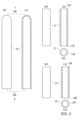
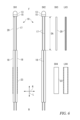
- Components of the temperature sensor in Figure 1 are shown, including a side view (SV1) and a cross-sectional view (LV1) showing a metal protection tube, a side view (SV2) showing a second heat-resistant insulator, a longitudinal cross-sectional view (LV2), and They are a front view (FV2), a side view (SV3) showing a caulking protective covering, a longitudinal cross-sectional view (LV3), and a front view (FV3).
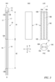
- a side view (SV1) showing a sensor element of the temperature sensor of FIG.
- FIG. 1 a side view (SV2) showing a first heat-resistant coating, a longitudinal cross-sectional view (LV2), and a front view (FV2).
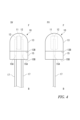
- 2 is a side view (SV) and a front view (FV) showing a heat sensitive body and its surroundings of the sensor element in FIG. 1.
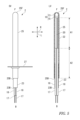
- FIG. It is a side view (SV) and a longitudinal cross-sectional view (LV) which show the temperature sensor based on 2nd Embodiment of this invention.
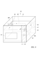
- FIG. 2 is a side view showing a state in which the temperature sensor according to the present embodiment is attached to an object to be measured. It is a figure showing an example of the cooking device concerning this embodiment.
- Both embodiments include a first heat-resistant insulator that electrically insulates the pair of lead wires from each other, and a second heat-resistant insulator that shields the current-carrying path between the pair of lead wires and the metal protective tube. They are common in that they are equipped with an insulator.
- the two embodiments differ in the materials and aspects of the first heat-resistant insulator and the second heat-resistant insulator.
- the temperature sensor according to this embodiment is suitable for applications requiring heat resistance of, for example, 500° C. and voltage resistance of, for example, over 1000V.
- the temperature sensor 1 includes a sensor element 10 and a metal protection tube 25 that houses the sensor element 10.
- Various elements are provided between the sensor element 10 and the protection tube 25, such as for electrical insulation in the temperature sensor 1.
- the side where the heat sensitive body 11 is provided is defined as the front (F), and the opposite side is defined as the rear (B).
- the definitions before and after this have relative meanings.
- an axial direction (L) and a radial direction (R) are defined. This definition is used for convenience of explanation of this embodiment, and does not specify the present invention.
- the sensor element 10 includes a heat sensitive body 11 formed in the shape of a rectangular parallelepiped, electrodes 12, 12 provided on each of two opposing surfaces of the heat sensitive body 11, and glass surrounding the heat sensitive body 11. a supporting tube 15 joined to the rear (B) end 13B of the covering 13, and a pair of conductive wires 17 electrically connected to the heat sensitive body 11 via the electrodes 12, 12. , 17.
- thermosensitive body 11 Figure 4
- a thermistor is applied to the heat sensitive body 11.
- a thermistor is an abbreviation for thermally sensitive resistor, and it is a metal oxide that measures temperature by utilizing the change in electrical resistance depending on temperature.
- Thermistors are classified into NTC (negative temperature coefficient) and PTC (positive temperature coefficient), but any thermistor can be used for the heat sensitive body 11.
- An oxide sintered body whose basic composition is manganese oxide (Mn 3 O 4 ) having a typical spinel structure as an NTC thermistor can be used for the heat sensitive body 11 .
- the heat sensitive body 11 is made of an oxide sintered body having a composition of M x Mn 3 - It can be used for. Furthermore, one or more of V, B, Ba, Bi, Ca, La, Sb, Sr, Ti, and Zr can be added. Further, a complex oxide having a perovskite structure typical of a PTC thermistor, for example, an oxide sintered body having a basic structure of YCrO 3 can be used for the heat sensitive body 11 .
- Electrode 12 is formed as a thick film or a thin film.
- the thick film electrode 12 is formed, for example, by applying a paste prepared by mixing platinum powder with an organic binder to both the front and back surfaces of the heat sensitive body 11 after sintering, drying, and then sintering the paste. Further, the thin film electrode 12 is formed by vacuum evaporation or sputtering.
- the glass cover 13 seals the heat sensitive element 11 and keeps it airtight, as shown in FIGS. This prevents chemical and physical changes in the heat sensitive body 11 and mechanically protects the heat sensitive body 11.
- the glass covering 13 covers the entire heat sensitive body 11 as well as the front (F) ends of the conductive wires 17, 17, and seals the conductive wires 17, 17.
- the covering 13 is made of amorphous glass or crystallized glass. Although each can be used alone, it is also possible to use a mixture of amorphous glass and crystallized glass so as to have a desired coefficient of thermal expansion.
- the crystallized glass for example, one composed of silicon oxide, calcium oxide, manganese oxide, and aluminum oxide is preferable, and more specifically, SiO 2 : 30 to 60 wt%, CaO: 10 to 30 wt%, MgO: 5 25 wt% and Al 2 O 3 :0 to 15 wt% can be used for the coating 13.
- it may be constructed using glass to which inorganic material powder is added.
- Inorganic material powders added to glass include aluminum oxide (Al 2 O 3 ), magnesium oxide (MgO), yttrium oxide (Y 2 O 3 ), chromium oxide (Cr 2 O 3 ), zirconium oxide (ZrO 2 ), etc. , metal oxides constituting the heat sensitive body 11, and the like.
- the support tube 15 mechanically reinforces the covering 13 by supporting the rear (B) end 13B of the covering 13, and provides electrical insulation and mechanical strength. Improve strength.
- the support tube 15 is made of a fine ceramic sintered body, such as aluminum oxide (Al 2 O 3 ) or silicon nitride (Si 3 N 4 ), which has higher mechanical strength than the covering body 13 .
- the support tube 15 is penetrated along the axial direction (L), and insertion passages 15A, 15A are formed through which the pair of conductive wires 17, 17 are passed, respectively. Note that for applications requiring low mechanical strength, the support tube 15 can be omitted.
- the front (F) sides of the conductive wires 17, 17 are electrically connected to electrodes 12, 12 formed on two opposing surfaces of the heat sensitive body 11. Since the front (F) side of each conductive wire 17 is sealed with the cover 13, Dumet wires having a coefficient of linear expansion close to that of glass are preferably used. Note that the Dumet wire is a conductive wire made of a cladding material in which an alloy whose main components are iron and nickel is used as a conductive core wire, and the core wire is covered with copper.
- a first heat-resistant insulator 19 is inserted into the front (F) side of the conductive wires 17, 17, and the first heat-resistant insulator 19 is inserted into the rear (B) side, which corresponds to the cylindrical insulator of the present invention.
- Insulating tubes 18, 18 are inserted therethrough.
- a caulking protective coating 23 is provided on the outside of the insulating tubes 18, 18 to collectively cover the conductive wires 17, 17 and the insulating tubes 18, 18.
- the conductive metal is exposed in a region other than where the insulating tube 18 is provided.
- First heat-resistant insulator 19 Figures 1 and 3
- the first area A1 in front (F) of the temperature sensor 1 is placed under a higher temperature than the second area A2 in the rear (B) of the first area A1 when the temperature sensor 1 measures the temperature. Therefore, a first heat-resistant insulator 19 is provided in the first region A1 in order to ensure electrical insulation between the pair of conductive wires 17, 17 even under high temperatures.
- the first heat-resistant insulator 19 is made of a material that can maintain its mechanical structure and electrical insulation performance even in the temperature range to which the first region A1 is exposed, for example, 500°C.
- the first heat-resistant insulator 19 in the first embodiment is made of a ceramic material such as aluminum oxide (Al 2 O 3 ), silicon nitride (Si 3 N 4 ), or aluminum nitride (AlN), for example.
- the first heat-resistant insulator 19 is a hollow cylindrical member provided with two wire receiving holes 19A, 19A penetrating in the axial direction (L), and has a length in the axial direction (L). The length is set to be equal to or longer than the area exposed to high temperatures, that is, the first area A1.
- a partition wall 19B is provided between the two wire receiving holes 19A, 19A in the radial direction (R), and electrically separates the conductive wires 17, 17 from each other. Further, an outer wall 19C is provided around the wire receiving holes 19A, 19A. Therefore, by providing the wire receiving holes 19A, 19A in the first heat-resistant insulator 19, the conductive wires 17, 17 are electrically insulated, and the conductive wires 17, 17 are connected to the protective tube 25, respectively. Electrical insulation is achieved.
- the rear (B) end of the conductive wire 17 is inserted from the front (F) end 19D of each wire receiving hole 19A, 19A, and the end 19D is inserted into the sensor element 10. It is slid to a position where the rear (B) end 15B of the support tube 15 abuts.
- An example of the electrical insulation performance (volume low efficiency ( ⁇ cm, 500° C.)) of a typical ceramic material constituting the first heat-resistant insulator 19 is shown below.
- the insulating tubes 18, 18 are for ensuring insulation between the two conductive wires 17, 17 on the rear (B) side and between each of the conductive wires 17, 17 and the protective tube 25. The wires 17, 17 are inserted through each of them.
- the insulating tubes 18, 18 are made of a resin material having electrical insulation, heat resistance, and weather resistance, such as a fluororesin formed into a tube shape. Examples of the fluororesin include polytetrafluoroethylene (PTFE), tetrafluoroethylene/perfluoroalkyl vinyl ether copolymer (PFA), and the like. Note that PTFE has a higher melting point than PFA.
- both PTFE and PFA have transparency, and PFA has particularly high transparency.
- the insulating tube 18 is not limited to these fluororesins, and may be made of any appropriate resin material, including thermoplastic resins and thermosetting resins. Note that since the second region A2, which is the region where the insulating tubes 18, 18 are disposed, has a lower temperature than the first region A1, the material of the insulating tubes 18, 18 is the first heat-resistant insulator 19. It is also possible to use a material with lower heat resistance.
- the front (F) end 18A of the insulating tube 18 is provided so as to come into contact with the rear (B) side end 19E of the first heat-resistant insulator 19, and from the rear (B) side end 18B, The rear (B) side ends of the inserted conductive wires 17, 17 extend.
- the insulating tubes 18, 18 are inserted into the conductive wires 17, 17 after the first heat-resistant insulator 19 is attached, and have a front (F) end 18A thereof and a rear (B) end of the first heat-resistant insulator 19. It is arranged at a position where the portion 19E comes into contact with the portion 19E.
- the rear (B) side end of the conductive wire 17 is exposed to the outside of the insulating tubes 18, 18 from the rear (B) end 18B.
- this invention is not limited to this. Instead of using the conductive wire 17 and the insulating tube 18 that are made separately, a so-called covered wire that is made integrally with the conductive wire 17 may be used.
- the second heat-resistant insulator 21 is provided between the first heat-resistant insulator 19 and the protective tube 25, and provides electrical insulation between the conductive wires 17, 17 housed in the first heat-resistant insulator 19 and the protective tube 25.
- the second heat-resistant insulator 21 is made of the same ceramic material as the first heat-resistant insulator 19, and has a cylindrical shape.
- the second heat-resistant insulator 21 has, for example, an outer diameter that is approximately equal to the inner diameter of the protection tube 25 and an inner diameter that is large enough to accommodate the first heat-resistant insulator 19 therein. As shown in FIG.
- the second heat-resistant insulator 21 has a front (F) end 21A fitted to the outside of the support tube 15 in the radial direction (R).
- the dimension in the length direction L of the second heat resistant insulator 21 is larger than the dimension in the length direction L of the first heat resistant insulator 19, and when the second heat resistant insulator 21 is housed in the protective tube 25, , the end 21B on the rear (B) side is set to a length that is located on the front (F) side of an attachment position 27A where a fixing flange 27, which will be described later, is provided.
- the sensor element 10 is housed in a protection tube 25, as shown in FIG.
- the sensor element 10 is fixed to the protection tube 25 by caulking the outer peripheral surface of the protection tube 25 toward its center. If this fixation by caulking is performed at a position where the protective tube 25 and the second heat-resistant insulator 21 overlap, there is a risk that the second heat-resistant insulator 21 will be damaged. Therefore, the caulking is performed at the rear (B) side of the end 21B of the second heat-resistant insulator 21, that is, at the position where the protective tube 25 and the insulating tube 18 overlap.
- a caulking protective coating 23 is provided. As shown in FIG. 1, the caulking protective coating 23 is provided between the outer circumferential surface of the insulating tubes 18, 18 and the inner circumferential surface of the protective tube 25, so that the caulking protective coating 23 is provided on the conductive wires 17, 17. Only an indirect force is applied through the Therefore, damage to the insulating tubes 18, 18 can be prevented.
- the caulking protective covering 23 is formed by forming a heat-resistant cloth such as glass cloth, silicate cloth, or alumina cloth into a tube shape, and inserting the insulating tubes 18, 18 into the tube.
- the inserted conductive wires 17, 17 are inserted.
- Glass cloth is an inorganic fiber fabric made of glass
- silica cloth is an inorganic fiber fabric whose main component is silicon oxide (SiO 2 )
- alumina cloth is an inorganic fiber fabric whose main component is aluminum oxide (Al 2 O 3 ). It is.
- the caulking protective covering 23 is inserted through the insulating tubes 18, 18 so that the front (F) end 23A is in contact with the end 21B of the second heat-resistant insulator 21, and the rear (B) end 23B is , are exposed from the protection tube 25.
- the dimension in the length direction L of the caulking protective sheathing 23 is set to such a length that a portion of the rear (B) of the conductive wires 17, 17 and the insulating tubes 18, 18 is exposed from the caulking protective sheath 23 toward the rear (B). has been done.
- Caulking is performed in an area where the caulking protective coating 23 is provided and which is covered by the protective tube 25. A specific method of caulking will be mentioned in the following description of the protection tube 25.
- the protective tube 25 is provided to hold the sensor element 10 and protect the sensor element 10 from vibrations, external forces, high heat, and combustion gas from outside the protective tube 25 .
- the protection tube 25 is formed in a dome shape with a closed front (F) end 25F that accommodates the heat sensitive element 11, and a rear (B) end 25B. It is formed into a cylindrical shape with an opening for drawing out the conductive wires 17, 17.
- the protection tube 25 is made of stainless steel, Ni-based superalloy, or other heat-resistant alloy. These alloys contain large amounts of Ni and Cr to ensure heat resistance.
- JIS NCF600 which is an example of a Ni-based superalloy, contains approximately 75 wt% Ni and 16 wt% Cr.
- the protective tube 25 Since the protective tube 25 is disposed inside the heating chamber 44 of a heating cooker in which the temperature sensor 1 is used, for example, a microwave oven 40 described below, it is exposed to an oxidizing atmosphere during use of the oven. Therefore, the surface of the protective tube 25 is oxidized as the oven is used. If the properties of the protection tube 25 change in this way, there is a risk that a detected temperature error will occur. Further, when the protective tube 25 is oxidized, the inside of the protective tube 25 becomes in a reduced state, and oxygen O 2 is taken away from the heat sensitive body 11 made of an oxide, thereby causing a composition shift in the heat sensitive body 11. Therefore, the characteristics of the heat sensitive body 11 may change, leading to a detection temperature error.
- the surface of the protective tube 25 is preferably oxidized in advance.
- the outer surface of the protective tube 25 is preferably black in order to improve heat collection.
- this embodiment can also exhibit colors other than black.
- the protection tube 25 protrudes into the heating chamber 44, the outer surface of the protection tube 25 and the wall surface of the heating chamber 44 can be made of similar colors. By doing so, the protection tube 25 can be made less noticeable inside the heating chamber 44.
- a black silicone resin-based heat-resistant paint can be applied in advance.
- Some of these silicone resin-based heat-resistant paints have a heat resistance of 600°C.
- Some silicone resin-based heat-resistant paints are made by combining silica (SiO 2 /silicon oxide) and organic substances (compounds mainly composed of carbon) to form organosilicon compounds, which are then made into polymers. Since the bonding strength of the (Si--O) bonds in silicone resins is considerably stronger than that of (CC) bonds in organic resins, silicone resins have high heat resistance.
- a black pigment such as graphite or carbon black, a black silicone resin heat-resistant paint can be obtained.
- the black color is preferably matte.
- the outer surface of the protective tube 25 can also be made black by applying black rust treatment. Normally, if a black rust finish is applied, the inner surface of the protective tube 25 will also be black.
- FIG. 7 shows the form of crimping 26A, 26A obtained by pressing a pair of convex crimping pieces (not shown) against the protective tube 25 in opposition.
- insulating tubes 18, 18 are mechanically connected to each other through a caulking protective coating 23 by forming recesses on two opposing sides of the protective tube 25 by plastic deformation. is fixed to the protection tube 25.
- the lower view of FIG. 7 shows the form of crimping 26A, 26A obtained by pressing a pair of convex crimping pieces (not shown) against the protective tube 25 in opposition.
- insulating tubes 18, 18 conductive wires 17, 17, not shown
- FIG. 7 shows the form of crimping 26B, 26B obtained by pressing a pair of concave crimping pieces (not shown) against the protective tube 25 in opposition.
- convex portions are formed by plastic deformation on two opposing sides of the protective tube 25, so that the insulating tubes 18, 18 (conductive wires 17, 17) (not shown) can be connected via the caulking protective coating 23.
- It is mechanically fixed to the protection tube 25.
- a fixing flange 27 for fixing the temperature sensor 1 to an object to be measured, such as an oven, is attached to the protective tube 25.
- the fixed flange 27 is formed to extend in the radial direction R of the protection tube 25.
- the side forward (F) from the attachment position 27A of the fixed flange 27, that is, the first region A1 of the protective tube 25 is inside the heating chamber under high temperature. It is arranged so as to protrude, and the side rearward (B) of the first region, that is, the rearward side (B) of the attachment position 27A of the fixed flange 27 is disposed outside the heating chamber.
- FIG. 7 shows an example in which the fixing flange 27 is caulked on the rear (B) side of the attachment position 27A, the caulking position is not limited to these.
- the caulking position may be on the rear (B) side of the first region which is under high temperature, that is, the front (F) of the fixed flange 27 as long as it is a region which is colder than the first region. good. Note that since the rear part (B) of the fixed flange 27 is located outside the heating chamber of the oven, the caulking is not exposed to high temperatures, and there is no fear that the caulking will loosen due to a rise in temperature.
- the temperature sensor 1 further includes a second heat-resistant insulator 21 in addition to a first heat-resistant insulator 19 for electrically insulating the conductive wires 17, 17 from each other.
- a second heat-resistant insulator 21 By shielding the conduction path between the conductive wires 17, 17 and the protective tube 25, the second heat-resistant insulator 21 can be used in environments where a particularly high withstand voltage between the conductive wires 17, 17 and the protective tube 25 is required. Even so, electrical insulation can be achieved more reliably.
- a temperature sensor 2 according to a second embodiment of the present invention will be described with reference to FIGS. 5 and 6.
- the main differences between the temperature sensor 2 and the temperature sensor 1 according to the first embodiment are a first heat-resistant insulator 19 and a first heat-resistant insulator 20 that electrically insulate the conductive wires 17, 17 from each other; , in the second heat-resistant insulator 21 and the second heat-resistant insulator 22.
- the temperature sensor 2 will be explained focusing on this difference, and the same components as the temperature sensor 1 will be given the same symbols as the temperature sensor 1, and the explanation will be omitted.
- the first heat-resistant insulator 20 covers only one of the two conductive wires 17, 17.
- the first heat-resistant insulator 20 is made of a material that can maintain its mechanical structure and electrical insulation performance even in the temperature range to which the first region A1 is exposed. Examples of this material include heat-resistant cloths such as the aforementioned glass cloth, silica cloth, and alumina cloth. This heat-resistant cloth is formed into a tube shape, and the conductive wire 17 is inserted into the tube to cover almost the entire first region A1 of one of the conductive wires 17. By doing so, electrical insulation performance between the pair of conductive wires 17, 17 is ensured while ensuring heat resistance.
- first heat-resistant insulators 20, 20 is prepared, and each of the conductive wires 17, 17 is connected to the first heat-resistant insulator 20. , 20.
- the second heat-resistant insulator 22 is a second heat-resistant insulator of the first embodiment in that a cylindrical insulating member having the same diameter from the front end (F) to the rear end (B) is used. It is the same as the heat-resistant insulator 21, but is different in that a glass member is used as the material.
- the main reason for selecting glass as the material for the second heat-resistant insulator 22 is as follows.
- the glass cylindrical member can suppress the degree of warpage even if it is long, so it has high precision in size and shape.
- the second heat-resistant insulator 22 is housed inside the protective tube 25, and since the protective tube 25 is made of a metal material, its dimensions and shape are highly accurate even if it is long. Therefore, the second heat-resistant insulator 22 housed inside the long protective tube 25 is also required to have high precision in size and shape. Therefore, in the second embodiment, a second heat-resistant insulator 22 made of glass is used.
- the reason why the warpage of a member made of a ceramic material tends to be large while the warp of a member made of glass can be reduced will be briefly mentioned below.
- Ceramic members are produced by press-molding raw material particles and sintering a molded body.
- the raw material particles join together, the gaps between the particles become smaller, and at the same time the compact shrinks to become a sintered body.
- variations in the degree of shrinkage may occur. This variation, that is, uneven shrinkage, is a cause of warping. It can be easily predicted that the degree of warping increases as the cylindrical member becomes longer and as the diameter decreases. It may not be practical to correct the warpage of the sintered body after sintering. For example, although warping can be corrected using methods such as cylindrical grinding, the number of man-hours and costs increase significantly.
- Glass members can be produced by melting raw materials and extrusion molding using this melt. This extruded molded product may also warp, but the warp can be corrected during the cooling process of the molded product. Therefore, even if the glass member is long, warping can be suppressed to a minimum.
- FIG. 8 shows a temperature sensor 1 (first embodiment) in which the second heat-resistant insulator 21 is made of a ceramic member and a temperature sensor 2 (second embodiment) in which the second heat-resistant insulator 22 is made of a glass member. ) is shown attached to the retaining wall 30. If the dimensions of the temperature sensor 2 projected into the heating area SA on the inside (left side in the figure) of the retaining wall 30 are OL2, and the dimensions of the temperature sensor 1 are OL1, then OL2>OL1, and the temperature sensor 2 is held better. The temperature at a position far from the wall 30 in the heating area SA can be accurately measured.
- First heat-resistant insulator 19 (ceramics); Inner diameter (wire accommodation hole): 0.6mm, outer diameter: 2.0mm, length: 12mm Second heat-resistant insulator 21 (ceramics); Inner diameter: 2.5mm, outer diameter: 3.0mm, length: 20mm Second heat-resistant insulator 22 (glass): Inner diameter: 2.5mm, outer diameter: 3.0mm, length: 80mm
- the temperature sensor 2 provides the following effects in addition to the effects provided by the temperature sensor 1. Since the second heat-resistant insulator 22 of the temperature sensor 2 is made of a cylindrical glass member having electrical insulation performance equivalent to that of a ceramic material, the second heat-resistant insulator 22 can be a long one. Therefore, according to the temperature sensor 2, even if the dimension projected into the temperature measurement target space is long, the temperature sensor 2 can be manufactured to a corresponding dimension.
- the glass material has high moisture absorption resistance, even when the temperature sensor 2 is used continuously, it is possible to suppress the deterioration of the electrical insulation performance. Further, if the second heat-resistant insulator 22 is made of a transparent glass material, the interior thereof can be easily confirmed visually during the production process of the temperature sensor 2, which is preferable for production control.
- the conductive wires 17, 17 are electrically insulated from each other by covering only one conductive wire 17 with the first heat-resistant insulator 20.
- the first heat-resistant insulator 20 is made of heat-resistant cloth formed into a tube shape. Therefore, the temperature sensor 2 can reduce the number of man-hours and cost spent on the second heat-resistant insulator 20.
- the microwave oven 40 includes an outer casing 41 having a rectangular shape, a control panel 42 provided with various operation buttons (not shown) on the front surface of the outer casing 41, and a control panel 42 provided on the side of the control panel 42.
- a door 43 is attached to the housing 41 so that it can be opened and closed freely.
- a heating chamber 44 is provided inside the outer casing 41, and an opening appears when the door 43 is opened.
- a space 45 separate from the inside of is provided.
- a ventilation fan 46 is provided inside the space 45 to take air into the space 45 from outside the outer casing 41 and heat it through a ventilation hole 48A provided in a side wall of the heating chamber 44 facing the space 45.
- the air is circulated inside the heating chamber 44 by passing through the heating chamber 44 and the outer casing 41 and discharging it to the outside of the outer casing 41 from another ventilation hole 48B provided on the opposite side. It is designed to form a wind flow WF.
- a microwave generator 47 is attached to the side surface of the heating chamber 44 inside the space 45 .
- a magnetron not shown
- an object to be heated on a turntable not shown
- a heater (not shown) is provided on the back side of the ceiling plate 49 of the heating chamber 44, and heats the ceiling or the air inside the heating chamber 44 to raise the atmospheric temperature inside the heating chamber 44.
- temperature sensors 1 and 2 are attached to the side wall of the heating chamber 44 facing the space 45. The temperature sensors 1 and 2 are attached so as to penetrate the side wall and protrude into the heating chamber 44 .
- the temperature sensor 2 in which the second heat-resistant insulator 22 is made of a glass member can increase the size (OL2) of the temperature sensor 2 projected into the heating area SA. . Therefore, it is preferable to apply the temperature sensor 2 in which the second heat-resistant insulator 22 is made of a glass member to the microwave oven 40 having the heating chamber 44 having a larger volume. On the other hand, for the heating chamber 44 having a small volume, it is possible to use the temperature sensor 1 in which the second heat-resistant insulator 21 is made of a ceramic member.
- first heat-resistant insulator 19 of the first embodiment and the first heat-resistant insulator 20 of the second embodiment can be replaced with each other.
Landscapes
- Physics & Mathematics (AREA)
- General Physics & Mathematics (AREA)
- Nonlinear Science (AREA)
- Engineering & Computer Science (AREA)
- Food Science & Technology (AREA)
- Measuring Temperature Or Quantity Of Heat (AREA)
- Resistance Heating (AREA)
Priority Applications (7)
| Application Number | Priority Date | Filing Date | Title |
|---|---|---|---|
| DE112022000379.0T DE112022000379T5 (de) | 2022-05-25 | 2022-05-25 | Temperatursensor und heizkocher |
| CN202411164816.8A CN118960983A (zh) | 2022-05-25 | 2022-05-25 | 温度传感器及加热烹调器 |
| JP2022565748A JP7259142B1 (ja) | 2022-05-25 | 2022-05-25 | 温度センサおよび加熱調理器 |
| US18/271,187 US12693169B2 (en) | 2022-05-25 | 2022-05-25 | Temperature sensor and heating cooker |
| PCT/JP2022/021346 WO2023228300A1 (ja) | 2022-05-25 | 2022-05-25 | 温度センサおよび加熱調理器 |
| CN202280008486.6A CN117460934B (zh) | 2022-05-25 | 2022-05-25 | 温度传感器及加热烹调器 |
| JP2023061123A JP7578746B2 (ja) | 2022-05-25 | 2023-04-05 | 温度センサおよび加熱調理器 |
Applications Claiming Priority (1)
| Application Number | Priority Date | Filing Date | Title |
|---|---|---|---|
| PCT/JP2022/021346 WO2023228300A1 (ja) | 2022-05-25 | 2022-05-25 | 温度センサおよび加熱調理器 |
Publications (1)
| Publication Number | Publication Date |
|---|---|
| WO2023228300A1 true WO2023228300A1 (ja) | 2023-11-30 |
Family
ID=85986368
Family Applications (1)
| Application Number | Title | Priority Date | Filing Date |
|---|---|---|---|
| PCT/JP2022/021346 Ceased WO2023228300A1 (ja) | 2022-05-25 | 2022-05-25 | 温度センサおよび加熱調理器 |
Country Status (5)
| Country | Link |
|---|---|
| US (1) | US12693169B2 (cg-RX-API-DMAC7.html) |
| JP (2) | JP7259142B1 (cg-RX-API-DMAC7.html) |
| CN (2) | CN117460934B (cg-RX-API-DMAC7.html) |
| DE (1) | DE112022000379T5 (cg-RX-API-DMAC7.html) |
| WO (1) | WO2023228300A1 (cg-RX-API-DMAC7.html) |
Families Citing this family (2)
| Publication number | Priority date | Publication date | Assignee | Title |
|---|---|---|---|---|
| JP7440459B2 (ja) * | 2021-05-19 | 2024-02-28 | 株式会社芝浦電子 | 温度センサ |
| CN117460934B (zh) * | 2022-05-25 | 2024-08-23 | 株式会社芝浦电子 | 温度传感器及加热烹调器 |
Citations (4)
| Publication number | Priority date | Publication date | Assignee | Title |
|---|---|---|---|---|
| JPH0355538U (cg-RX-API-DMAC7.html) * | 1989-10-03 | 1991-05-29 | ||
| JPH0630740U (ja) * | 1992-09-28 | 1994-04-22 | 株式会社芝浦電子製作所 | サーミスタ温度センサ |
| JP2010261860A (ja) * | 2009-05-08 | 2010-11-18 | Shibaura Electronics Co Ltd | 温度センサ及び温度センサシステム |
| KR101004404B1 (ko) * | 2010-07-29 | 2010-12-28 | 한국쎄미텍 주식회사 | 온도센서 구조 및 그 조립방법 |
Family Cites Families (14)
| Publication number | Priority date | Publication date | Assignee | Title |
|---|---|---|---|---|
| US3500280A (en) * | 1967-08-21 | 1970-03-10 | John D Ensign | Temperature sensing probe |
| GB2360591B (en) | 2000-03-23 | 2004-04-28 | Ceramaspeed Ltd | Temperature sensor |
| JP2004225921A (ja) | 2002-12-20 | 2004-08-12 | Shibaura Electronics Co Ltd | オーブンレンジ用温度センサ及びオーブンレンジ |
| US7121722B2 (en) * | 2003-05-02 | 2006-10-17 | Ngk Spark Plug Co., Ltd. | Temperature sensor |
| JP4041018B2 (ja) | 2003-06-25 | 2008-01-30 | Tdk株式会社 | 温度センサ |
| JP5324536B2 (ja) | 2010-08-19 | 2013-10-23 | 日本特殊陶業株式会社 | 温度センサ |
| JP5229355B2 (ja) | 2010-09-27 | 2013-07-03 | 株式会社デンソー | 温度センサ |
| US9791328B2 (en) * | 2013-12-18 | 2017-10-17 | Ewig Industries Macao Commercial Offshore Ltd | Waterproof food thermometer probe and associated methods |
| JP2016130633A (ja) | 2015-01-13 | 2016-07-21 | アズビル株式会社 | 温度センサ |
| EP3825668B1 (en) | 2017-04-11 | 2022-11-02 | Shibaura Electronics Co., Ltd. | Temperature sensor |
| DE102018108240A1 (de) | 2018-04-06 | 2019-10-10 | Alinox Ag | Verfahren zum Herstellen einer Metallplatte mit eingebettetem Temperatursensor, sowie danach hergestellte Metallplatte |
| CN208635938U (zh) | 2018-07-26 | 2019-03-22 | 恒新基电子(青岛)有限公司 | 一种微波炉用温度传感器 |
| US11808634B2 (en) * | 2019-11-15 | 2023-11-07 | Shibaura Electronics Co., Ltd. | Temperature sensor, temperature sensor element, and method for manufacturing temperature sensor |
| CN117460934B (zh) | 2022-05-25 | 2024-08-23 | 株式会社芝浦电子 | 温度传感器及加热烹调器 |
-
2022
- 2022-05-25 CN CN202280008486.6A patent/CN117460934B/zh active Active
- 2022-05-25 US US18/271,187 patent/US12693169B2/en active Active
- 2022-05-25 CN CN202411164816.8A patent/CN118960983A/zh active Pending
- 2022-05-25 DE DE112022000379.0T patent/DE112022000379T5/de active Pending
- 2022-05-25 WO PCT/JP2022/021346 patent/WO2023228300A1/ja not_active Ceased
- 2022-05-25 JP JP2022565748A patent/JP7259142B1/ja active Active
-
2023
- 2023-04-05 JP JP2023061123A patent/JP7578746B2/ja active Active
Patent Citations (4)
| Publication number | Priority date | Publication date | Assignee | Title |
|---|---|---|---|---|
| JPH0355538U (cg-RX-API-DMAC7.html) * | 1989-10-03 | 1991-05-29 | ||
| JPH0630740U (ja) * | 1992-09-28 | 1994-04-22 | 株式会社芝浦電子製作所 | サーミスタ温度センサ |
| JP2010261860A (ja) * | 2009-05-08 | 2010-11-18 | Shibaura Electronics Co Ltd | 温度センサ及び温度センサシステム |
| KR101004404B1 (ko) * | 2010-07-29 | 2010-12-28 | 한국쎄미텍 주식회사 | 온도센서 구조 및 그 조립방법 |
Also Published As
| Publication number | Publication date |
|---|---|
| JP7578746B2 (ja) | 2024-11-06 |
| US12693169B2 (en) | 2026-07-28 |
| JPWO2023228300A1 (cg-RX-API-DMAC7.html) | 2023-11-30 |
| CN118960983A (zh) | 2024-11-15 |
| JP2023174523A (ja) | 2023-12-07 |
| CN117460934A (zh) | 2024-01-26 |
| JP7259142B1 (ja) | 2023-04-17 |
| CN117460934B (zh) | 2024-08-23 |
| DE112022000379T5 (de) | 2024-02-08 |
| US20240385050A1 (en) | 2024-11-21 |
Similar Documents
| Publication | Publication Date | Title |
|---|---|---|
| JP7578746B2 (ja) | 温度センサおよび加熱調理器 | |
| JPWO2013072961A1 (ja) | 温度センサおよび機器 | |
| CA1157166A (en) | Composite thermistor component | |
| JP4963311B2 (ja) | 計測用温度センサ | |
| JP6279284B2 (ja) | 温度センサ | |
| CN102341683A (zh) | 用于气体分析设备的红外辐射器装置 | |
| CN115103607A (zh) | 具有陶瓷加热器基部的气溶胶产生装置 | |
| JP2010032237A (ja) | 温度センサ | |
| US6040519A (en) | Unit sheath | |
| JP2980710B2 (ja) | センサの防水構造及びセンサの製造方法 | |
| JPWO2023228300A5 (cg-RX-API-DMAC7.html) | ||
| US10767862B2 (en) | Flame rod | |
| CN116940815B (zh) | 温度传感器 | |
| JP4892030B2 (ja) | 温度センサ | |
| JP7304328B2 (ja) | 温度センサ、および、加熱器 | |
| EP0650020B1 (en) | A ceramic heater and a method of manufacture thereof | |
| JP2532358B2 (ja) | 管状発熱体 | |
| JP3075660B2 (ja) | セラミックスヒータ及びその製造方法 | |
| CN1088902C (zh) | 正温度系数热敏装置 | |
| JP2701565B2 (ja) | 薄膜サーミスタおよびその製造方法 | |
| JPH07153552A (ja) | Ptc発熱装置 | |
| JP2010272805A (ja) | サーミスタ素子とその製造方法 | |
| JPH0247494Y2 (cg-RX-API-DMAC7.html) | ||
| JP2006108221A (ja) | 高温耐熱型サーミスタ | |
| JPH0245806Y2 (cg-RX-API-DMAC7.html) |
Legal Events
| Date | Code | Title | Description |
|---|---|---|---|
| ENP | Entry into the national phase |
Ref document number: 2022565748 Country of ref document: JP Kind code of ref document: A |
|
| WWE | Wipo information: entry into national phase |
Ref document number: 202280008486.6 Country of ref document: CN |
|
| WWE | Wipo information: entry into national phase |
Ref document number: 18271187 Country of ref document: US |
|
| WWE | Wipo information: entry into national phase |
Ref document number: 112022000379 Country of ref document: DE |
|
| 121 | Ep: the epo has been informed by wipo that ep was designated in this application |
Ref document number: 22943704 Country of ref document: EP Kind code of ref document: A1 |
|
| 122 | Ep: pct application non-entry in european phase |
Ref document number: 22943704 Country of ref document: EP Kind code of ref document: A1 |
|
| WWG | Wipo information: grant in national office |
Ref document number: 18271187 Country of ref document: US |