WO2023224030A1 - 情報処理方法、情報処理装置、及び情報処理プログラム - Google Patents
情報処理方法、情報処理装置、及び情報処理プログラム Download PDFInfo
- Publication number
- WO2023224030A1 WO2023224030A1 PCT/JP2023/018245 JP2023018245W WO2023224030A1 WO 2023224030 A1 WO2023224030 A1 WO 2023224030A1 JP 2023018245 W JP2023018245 W JP 2023018245W WO 2023224030 A1 WO2023224030 A1 WO 2023224030A1
- Authority
- WO
- WIPO (PCT)
- Prior art keywords
- icon
- photographing
- information processing
- information
- shooting
- Prior art date
- Legal status (The legal status is an assumption and is not a legal conclusion. Google has not performed a legal analysis and makes no representation as to the accuracy of the status listed.)
- Ceased
Links
Images



Classifications
-
- G—PHYSICS
- G06—COMPUTING OR CALCULATING; COUNTING
- G06F—ELECTRIC DIGITAL DATA PROCESSING
- G06F3/00—Input arrangements for transferring data to be processed into a form capable of being handled by the computer; Output arrangements for transferring data from processing unit to output unit, e.g. interface arrangements
- G06F3/01—Input arrangements or combined input and output arrangements for interaction between user and computer
- G06F3/048—Interaction techniques based on graphical user interfaces [GUI]
- G06F3/0481—Interaction techniques based on graphical user interfaces [GUI] based on specific properties of the displayed interaction object or a metaphor-based environment, e.g. interaction with desktop elements like windows or icons, or assisted by a cursor's changing behaviour or appearance
- G06F3/04817—Interaction techniques based on graphical user interfaces [GUI] based on specific properties of the displayed interaction object or a metaphor-based environment, e.g. interaction with desktop elements like windows or icons, or assisted by a cursor's changing behaviour or appearance using icons
-
- G—PHYSICS
- G06—COMPUTING OR CALCULATING; COUNTING
- G06F—ELECTRIC DIGITAL DATA PROCESSING
- G06F3/00—Input arrangements for transferring data to be processed into a form capable of being handled by the computer; Output arrangements for transferring data from processing unit to output unit, e.g. interface arrangements
- G06F3/01—Input arrangements or combined input and output arrangements for interaction between user and computer
- G06F3/048—Interaction techniques based on graphical user interfaces [GUI]
- G06F3/0481—Interaction techniques based on graphical user interfaces [GUI] based on specific properties of the displayed interaction object or a metaphor-based environment, e.g. interaction with desktop elements like windows or icons, or assisted by a cursor's changing behaviour or appearance
- G06F3/04815—Interaction with a metaphor-based environment or interaction object displayed as three-dimensional [3D], e.g. changing the user viewpoint with respect to the environment or object
-
- G—PHYSICS
- G06—COMPUTING OR CALCULATING; COUNTING
- G06F—ELECTRIC DIGITAL DATA PROCESSING
- G06F3/00—Input arrangements for transferring data to be processed into a form capable of being handled by the computer; Output arrangements for transferring data from processing unit to output unit, e.g. interface arrangements
- G06F3/01—Input arrangements or combined input and output arrangements for interaction between user and computer
- G06F3/048—Interaction techniques based on graphical user interfaces [GUI]
- G06F3/0484—Interaction techniques based on graphical user interfaces [GUI] for the control of specific functions or operations, e.g. selecting or manipulating an object, an image or a displayed text element, setting a parameter value or selecting a range
- G06F3/04845—Interaction techniques based on graphical user interfaces [GUI] for the control of specific functions or operations, e.g. selecting or manipulating an object, an image or a displayed text element, setting a parameter value or selecting a range for image manipulation, e.g. dragging, rotation, expansion or change of colour
-
- G—PHYSICS
- G06—COMPUTING OR CALCULATING; COUNTING
- G06F—ELECTRIC DIGITAL DATA PROCESSING
- G06F3/00—Input arrangements for transferring data to be processed into a form capable of being handled by the computer; Output arrangements for transferring data from processing unit to output unit, e.g. interface arrangements
- G06F3/01—Input arrangements or combined input and output arrangements for interaction between user and computer
- G06F3/048—Interaction techniques based on graphical user interfaces [GUI]
- G06F3/0484—Interaction techniques based on graphical user interfaces [GUI] for the control of specific functions or operations, e.g. selecting or manipulating an object, an image or a displayed text element, setting a parameter value or selecting a range
- G06F3/0486—Drag-and-drop
-
- G—PHYSICS
- G06—COMPUTING OR CALCULATING; COUNTING
- G06T—IMAGE DATA PROCESSING OR GENERATION, IN GENERAL
- G06T1/00—General purpose image data processing
-
- G—PHYSICS
- G06—COMPUTING OR CALCULATING; COUNTING
- G06T—IMAGE DATA PROCESSING OR GENERATION, IN GENERAL
- G06T11/00—Two-dimensional [2D] image generation
- G06T11/60—Creating or editing images; Combining images with text
- G06T11/65—Creating or editing images; Combining images with text on geographic maps
-
- G—PHYSICS
- G06—COMPUTING OR CALCULATING; COUNTING
- G06Q—INFORMATION AND COMMUNICATION TECHNOLOGY [ICT] SPECIALLY ADAPTED FOR ADMINISTRATIVE, COMMERCIAL, FINANCIAL, MANAGERIAL OR SUPERVISORY PURPOSES; SYSTEMS OR METHODS SPECIALLY ADAPTED FOR ADMINISTRATIVE, COMMERCIAL, FINANCIAL, MANAGERIAL OR SUPERVISORY PURPOSES, NOT OTHERWISE PROVIDED FOR
- G06Q50/00—Information and communication technology [ICT] specially adapted for implementation of business processes of specific business sectors, e.g. utilities or tourism
- G06Q50/08—Construction
-
- G—PHYSICS
- G06—COMPUTING OR CALCULATING; COUNTING
- G06T—IMAGE DATA PROCESSING OR GENERATION, IN GENERAL
- G06T2200/00—Indexing scheme for image data processing or generation, in general
- G06T2200/24—Indexing scheme for image data processing or generation, in general involving graphical user interfaces [GUIs]
Definitions
- the present disclosure relates to a technique for selecting images.
- Patent Document 1 discloses that an image (e.g., a contour line) indicating a designated area specified by a worker is displayed on a bird's-eye view image of a work site, and an input is made by the worker in a display field provided next to the bird's-eye view image. Displaying chats related to a designated area that has been created is disclosed.
- an image e.g., a contour line
- An object of the present disclosure is to provide a technology that allows detailed confirmation of the state of the site shown in a bird's-eye view from a distance.
- An information processing method is an information processing method in a computer, in which a bird's eye view is displayed on a display of a terminal device, and a plurality of shooting point icons indicating shooting points are displayed on the bird's eye view, and an arbitrary number of shooting point icons in the bird's eye view are displayed on the display of a terminal device.
- a selection icon for selecting a position the selection icon is configured to be movable on the bird's-eye view
- the plurality of shooting point icons correspond to image information indicating images shot at the shooting point. detect the movement completed position of the selected icon, determine one shooting point icon based on the movement completed position and the position of each shooting point icon, and create an image associated with the first shooting point icon. Outputting information to the display.
- the state of the site shown in the bird's-eye view can be confirmed in detail from a distance.
- FIG. 1 is a block diagram illustrating an example of the configuration of an information processing system in an embodiment of the present disclosure. It is a figure showing an example of a display screen displayed on a display of a terminal device.
- FIG. 3 is an enlarged view of the image information display field and annotation information display field shown in FIG. 2; It is a figure which shows the design drawing display column when a selection icon is moved.
- 2 is a flowchart showing an example of processing of the information processing apparatus shown in FIG. 1.
- FIG. 6 is a flowchart showing details of the display processing shown in FIG. 5.
- FIG. 1 is a block diagram illustrating an example of the configuration of an information processing system in an embodiment of the present disclosure. It is a figure showing an example of a display screen displayed on a display of a terminal device.
- FIG. 3 is an enlarged view of the image information display field and annotation information display field shown in FIG. 2; It is a figure which shows the design drawing display column when a selection icon is moved.
- 2 is a flowchar
- Issues at construction sites include communication issues such as not being able to convey specific instructions to workers, the time it takes to explain those instructions, the need for manpower to go around the entire construction site, and the time it takes to travel to the construction site. There are challenges in confirming construction sites, such as this.
- An information processing method in an aspect of the present disclosure is an information processing method in a computer, which displays a bird's eye view on a display of a terminal device, and displays a plurality of shooting point icons indicating shooting points on the bird's eye view; a selection icon for selecting an arbitrary position on the bird's-eye view; the selection icon is configured to be movable on the bird's-eye view; and the plurality of shooting point icons include images indicating images shot at the shooting points.
- the information is associated with each other, the movement completion position of the selected icon is detected, one shooting point icon is determined based on the movement completion position and the position of each shooting point icon, and the one shooting point icon is associated with the one shooting point icon.
- the obtained image information is output to the display.
- a plurality of shooting point icons and selection icons are displayed on the bird's eye view.
- one photographing point icon is determined based on the movement completed position and the position of each photographing point icon.
- Image information associated with the determined one shooting point icon is displayed. This image information indicates an image photographed at the photographing point. This allows the user to remotely check the situation at the shooting location. Therefore, the user viewing the image information can remotely check the situation at the site shown in the bird's-eye view in detail. Furthermore, since image information can be displayed through such a simple operation, the number of computer processing steps required for the operation can be reduced.
- the plurality of photographing point icons include a first photographing point icon associated with annotation information, and in the determination, the movement completion position is one of the plurality of photographing point icons. If the point icon is located outside a predetermined area from the position of each point icon, the first shooting point icon closest to the movement completion position is determined as the first shooting point icon, and in the output, the selected first shooting point Image information and annotation information associated with the icon may be output to the display.
- the user can move the first shooting point icon. You can choose. Therefore, the user can select the first photographing point icon without performing detailed operations such as moving the selection icon within a predetermined range from the first photographing point icon.
- the user can easily view annotation information and image information related to the annotation information with simple operations. Note that when a bird's-eye view is shared by multiple users, it is considered that there are many cases in which each user desires to preferentially view annotation information added to a shooting point by another user. Therefore, this configuration is useful for meeting such needs.
- the photographing point icon is It may be determined as one shooting point icon.
- the user by moving the selection icon from the position of any of the shooting point icons into the predetermined area, the user can view the image information associated with the shooting point icon.
- the current position of the selected icon that is moving is further detected, and a predetermined number of photographing points are selected in order of distance from the current position. Icons may be determined and the predetermined number of photographing point icons may be highlighted.
- the highlighting may include displaying each of the predetermined number of shooting point icons enlarged to a size that represents a predetermined area. May include.
- the selected point icon is enlarged to the size representing the predetermined area, so the user can recognize the size of the predetermined area, and the user can The selection becomes easier.
- the plurality of photographing point icons include a first photographing point icon associated with annotation information, and the first photographing point icon is associated with an annotation icon.
- the highlighting may include enlarging and displaying an annotation icon associated with the first photographing point icon. May include.
- the annotation icon is enlarged, so that the shooting point icon near the selection icon is This allows the user to more reliably recognize that the icon is a photographing point icon that has been taken.
- the bird's-eye view is a design drawing
- the image information is acquired by an omnidirectional camera at a construction site represented by the design drawing. A photographed image may also be shown.
- the selection icon may be moved by dragging, and the movement completion position may be a drop position of the selection icon.
- the user can select the shooting location icon by dragging and dropping the selection icon.
- the image information includes an object region indicating an object included in the image indicated by the image information
- the annotation Information may indicate annotations associated with the object
- the user can confirm the annotation related to the object included in the image indicated by the image information.
- An information processing device is an information processing device including a processor, the processor displaying a bird's eye view on a display of a terminal device, and displaying a plurality of photographic points on the bird's eye view. and a selection icon for selecting an arbitrary position in the bird's-eye view, the selection icon is configured to be movable in the bird's-eye view, and the plurality of shooting point icons include a plurality of shooting point icons, and a selection icon for selecting an arbitrary position on the bird's-eye view.
- the selected icon is associated with the image information
- the movement completed position of the selected icon is detected
- one shooting point icon is determined based on the movement completed position and the position of each shooting point icon
- the one shooting point icon is A process of outputting image information associated with the image information to the display is executed.
- An information processing program causes a computer to execute the information processing method described in any one of (1) to (9) above.
- the present disclosure can also be realized as an information processing system operated by such an information processing program. Further, it goes without saying that such a computer program can be distributed via a computer-readable non-transitory recording medium such as a CD-ROM or a communication network such as the Internet.
- a computer-readable non-transitory recording medium such as a CD-ROM or a communication network such as the Internet.
- FIG. 1 is a block diagram illustrating an example of the configuration of an information processing system 1 in an embodiment of the present disclosure.
- the information processing system 1 includes an information processing device 10, a photographing device 20, and a terminal device 30.
- the information processing device 10, the photographing device 20, and the terminal device 30 are communicably connected via a network.
- An example of a network is the Internet.
- the information processing device 10 is, for example, a cloud server configured of one or more computers. However, this is just an example, and the information processing device 10 may be configured as an edge server or may be implemented in the terminal device 30.
- the photographing device 20 is composed of, for example, an omnidirectional camera, and photographs images at a predetermined frame rate.
- the photographing device 20 is, for example, a portable photographing device carried by a user.
- the users are, for example, construction site workers and site supervisors. The user moves within the construction site while photographing the construction site with the photographing device 20.
- the photographing device 20 transmits image information indicating the photographed image to the information processing device 10 via the network.
- the image information is associated with the location of the shooting point indicating the shooting point and the date and time of the shooting.
- the position of the photographing point is acquired by a position sensor such as a magnetic sensor or a GPS sensor included in the photographing device 20, and is expressed in latitude and longitude.
- the photographing date and time is acquired, for example, by a clock included in the photographing device 20.
- the information processing device 10 can obtain image information at a plurality of photographing points at the construction site.
- the photographing device 20 photographs images at a predetermined frame rate, the photographing point is defined in units of frame cycles. However, this is just an example, and the shooting points may be defined for each predetermined time (for example, 1 second, 1 minute, etc.).
- the photographing device 20 includes an image sensor, an operating device, a communication circuit, a signal processing circuit, and the like.
- the photographing device 20 may be configured with a portable computer such as a smartphone or a doublet computer.
- the terminal device 30 is owned by a user.
- the terminal device 30 may be configured with a portable computer such as a smartphone or a tablet computer, or may be configured with a stationary computer.
- the terminal device 30 displays screen information on a display under the control of the information processing device 10.
- a plurality of terminal devices may be connected to the information processing device 10 via a network.
- the terminal device 30 includes a central processing unit (CPU), a memory, a display, operation devices such as a touch panel and a keyboard, and a communication circuit.
- the information processing device 10 includes a processor 11, a memory 12, and a communication unit 13.
- the processor 11 is composed of, for example, a central processing unit (CPU).
- the processor 11 includes an acquisition section 111, a determination section 112, and an output section 113.
- the acquisition unit 111 to the output unit 113 may be realized by the processor 11 executing an information processing program, or may be configured with a dedicated hardware circuit such as an ASIC.
- the acquisition unit 111 acquires an instruction from the user to select a blueprint from the terminal device 30, reads the blueprint information indicated by the instruction from the memory 12, and displays the read blueprint information on the display of the terminal device 30.
- the blueprint information is information indicating a blueprint of a construction site.
- the blueprint information is an example of a bird's eye view.
- the acquisition unit 111 displays on the terminal device 30 a plurality of photographing point icons indicating photographing points on the blueprint and a selection icon for selecting an arbitrary position on the blueprint. These displays are realized by the acquisition unit 111 transmitting display instructions to the terminal device 30 using the communication unit 13.
- the selection icon is configured to be movable on the blueprint.
- the acquisition unit 111 displays a photographing point icon at a position on the blueprint corresponding to the photographing point.
- latitude and longitude are associated with key points in advance. Key points are, for example, the four corners of the blueprint.
- the determining unit 112 acquires from the terminal device 30 the current position of the selected icon that is moved on the blueprint by the user's operation. This current position is the coordinate on the blueprint.
- the determining unit 112 detects the position at which the selected icon has been moved.
- the selection icon is configured to be movable by drag-and-drop operation.
- the movement completion position will be referred to as the drop position.
- the determining unit 112 may detect the current position of the selected icon as the drop position when the operation information indicating a drop operation is acquired from the terminal device 30 via the communication unit 13.
- the determining unit 112 determines one photographing point icon based on the detected drop position and the position of each photographing point icon.
- the plurality of shooting point icons include a first shooting point icon that is associated with image information and annotation information.
- the annotation information indicates an annotation input using the terminal device 30 by the user who viewed the image information.
- the user uses the terminal device 30 to input an object area indicating an object included in the image indicated by the image information.
- Annotations are attached to this object.
- the annotation may be a message indicating what should be noted during work regarding this object.
- An annotation icon indicating that there is an annotation is displayed in association with the first photographing point icon.
- the determining unit 112 determines the first photographing point icon closest to the drop position as the one photographing point icon.
- the determining unit 112 determines the shooting point icon as one selected point icon.
- the determining unit 112 determines a predetermined number of photographing point icons in order of proximity to the current position of the selected icon acquired from the terminal device 30 via the communication unit 13, and highlights the predetermined number of photographing point icons.
- a predetermined number an appropriate value such as 1, 2, 3, etc. can be adopted.
- the highlighting includes displaying each of the predetermined number of shooting point icons enlarged to a size that represents a predetermined area.
- the highlighting includes, when the first photographing point is included in the predetermined number of photographing point icons, enlarging and displaying the annotation icon associated with the first photographing point icon.
- the output unit 113 reads the image information associated with the one shooting point icon determined by the determining unit 112 from the memory 12 and displays the read image information on the display of the terminal device 30. If the first selected icon is the first shooting point icon, the output unit 113 reads the image information and annotation information associated with the first shooting point icon from the memory 12, and outputs the obtained image information and annotation information to the terminal. It may be displayed on the display of the device 30. On the other hand, if the first selected icon is not the first shooting location icon, the output unit 113 reads the image information associated with the first shooting location icon from the memory 12 and displays the obtained image information on the display of the terminal device 30. It should be displayed in . Here, the output unit 113 may display the image information and annotation information on the display of the terminal device 30 by transmitting the image information and annotation information read from the memory 12 to the terminal device 30 using the communication unit 13. .
- the memory 12 is composed of a nonvolatile rewritable storage device such as a hard disk drive or solid state drive.
- the memory 12 stores blueprint information, photographing information, annotation information, and image information.
- the blueprint information is image information showing the blueprint.
- the blueprint information is associated with a blueprint ID that identifies the blueprint. As described above, the latitude and longitude of the actual construction site are set at key points in the blueprint.
- the photographing information indicates information regarding one photographing operation using the photographing device 20. Photographing information is generated every time one photographing operation is performed.
- One photographing operation refers to a series of operations from when a worker holding the photographing device 20 starts photographing at a construction site to when the worker finishes photographing.
- a plurality of images are photographed by one photographing operation.
- the photographing information includes a blueprint ID, a photographing ID, a photographing date and time, a representative value of the photographing date and time, a position of a photographing point, and a position of a photographing point icon.
- the blueprint ID is an identifier of the photographed blueprint of the construction site.
- the photographing ID is an identifier for identifying each photograph included in one photographing operation.
- the photographing date and time is the photographing date and time of the photographing indicated by the photographing ID.
- the representative value of the photographing date and time is the photographing date and time when photographing was started.
- the photographing point indicates the position (latitude and longitude) where the photographing indicated by the photographing ID was taken.
- the position of the photographing point icon indicates the display position (coordinates) of the photographing point icon corresponding to the photographing ID on the design drawing.
- the location of the photographing point icon is based on the photographing position (latitude and longitude) at the key point of the blueprint indicated by the blueprint information and the photographing point (latitude and longitude) corresponding to the photographing ID. Calculated by mapping.
- Annotation information is information indicating an annotation.
- One piece of annotation information corresponds to one annotation.
- the annotation information is associated with a shooting ID and an object area ID.
- the object region ID is an identifier of an object region set in the image information corresponding to the photographing ID and to which an annotation has been added.
- the image information indicates one image photographed by each photograph included in one photographing operation.
- the image information is associated with a shooting ID and an object area ID.
- the image information includes the plurality of object region IDs.
- the object area information stores the position (coordinates) of the key point of the object area set in the image information corresponding to the shooting ID. Key points are vertices on the contour of the object region.
- a shooting ID and an object area ID are associated with each other.
- the image information corresponding to the photographing point icon is specified using the photographing ID as a key. Since the annotation information and the object area information are associated with the object area ID, the annotation information corresponding to the object area information is specified using the object area ID as a key. Since the object area information and the image information are associated with the photographing ID, the image information corresponding to the object area information is specified using the photographing ID as a key. The photographing point icon corresponding to the photographing ID associated with the annotation information becomes the first photographing point icon.
- the communication unit 13 is a communication circuit that connects the information processing device 10 to a network.
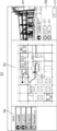
- FIG. 2 is a diagram showing an example of the display screen G1 displayed on the display of the terminal device 30.
- the display screen G1 is a basic screen of an application provided by the information processing device 10.
- the display screen G1 includes an image information display field R1, an annotation information display field R2, a blueprint display field R3, and a news display field R4.
- the image information display column R1 displays image information associated with one shooting point icon determined by the determination unit 112.
- the annotation information display field R2 displays annotation information associated with the one determined shooting location icon.
- a list of annotations C1 input by a plurality of users with respect to the image information displayed in the image information display field R1 is displayed.
- the annotation C1 input by a user other than the user is displayed on the left side, and the annotation C1 input by the user himself is displayed on the right side.
- the blueprint display field R3 displays blueprints of the construction site.
- a selection icon 201, a photographing point icon 202, and a trajectory 203 are displayed in a superimposed manner on the blueprint displayed in the blueprint display field R3.
- the selection icon 201 is configured to be movable by a drag-and-drop operation.
- the selection icon 201 is composed of an image simulating a person.
- the photographing point icon 202 is an icon indicating a photographing point, and is associated with image information.
- the shooting location icon 202 is composed of a circular image.
- a trajectory 203 indicates the trajectory of the user who captured the image information.
- the trajectory 203 is composed of lines connecting adjacent shooting point icons 202.
- the shooting point icon 202 located at the tip of the trajectory 203 and the shooting point icon 202 located at the trailing end of the trajectory 203 are displayed in a larger size than other shooting point icons.
- a photographing point icon 202 located at the leading end (for example, the right end) of the trajectory 203 indicates the photographing start position
- a photographing point icon 202 located at the trailing end (for example, the left end) of the trajectory 203 indicates the photographing end position.
- the news display column R4 displays various messages related to this construction site and input by the user.
- FIG. 3 is an enlarged view of the image information display field R1 and annotation information display field R2 shown in FIG. 2.
- An object region D1 is set in the image information.
- the object region D1 indicates the region of the object of interest input by the user in response to the image information displayed in the image information display field R1.
- the terminal device 30 displays a frame (not shown) for selecting the object region D1 in the image information display field R1. Display.
- This frame is, for example, rectangular.
- the user operates the terminal device 30 to move and deform the frame so that it is superimposed on a certain object displayed in the image information display field R1. This sets the object area D1.
- an object area D1 is set on the ground in front of a building under construction.
- Object area information indicating the set object area D1 is stored in the memory 12 in association with the object area ID and image ID.
- the object region information includes coordinates indicating key points of the object region D1.
- the key point is, for example, the vertex of the object region D1.
- Annotation C1 is an annotation input by the user for object region D1.
- the annotation information indicating this annotation C1 is stored in the memory 12 in association with the object area ID of the object area D1.
- Object area information indicating each of a plurality of object areas is individually assigned an object area ID and stored in the memory 12.
- FIG. 4 is a diagram showing the blueprint display field R3 when the selection icon 201 is moved.
- the selection icon 201 has been dragged in the direction indicated by the arrow.
- the determining unit 112 calculates the distances between the position (coordinates) of the selection icon 201 and the positions (coordinates) of the plurality of shooting point icons 202 on the trajectory 203.
- the top three shooting point icons 202 (an example of a predetermined number) in descending order of distance are shooting point icons 202(1), 202(2), and 202(3). Therefore, the photographing point icons 202(1), 202(2), and 202(3) are displayed enlarged to a size indicating the predetermined area D2. This allows the user to recognize the shooting point icon 202 that is close to the selection icon 201, and also allows the user to recognize the size of the predetermined area D2.
- the shooting point icon 202(2) is the shooting point icon 202 associated with the annotation icon 204, that is, the first shooting point icon. Therefore, this annotation icon 204 is also displayed in an enlarged manner.
- the annotation icon 204 is an icon indicating that there is an annotation, and in the example of FIG. 4, a speech bubble mark is adopted.
- the shooting point icon 202(4) is also the shooting point icon 202 associated with the annotation icon 204, that is, the first shooting point icon. Since the photographing point icon 202(4) is not in the top three in terms of distance to the selection icon 201, the annotation icon 204 is not displayed in an enlarged manner.
- the selection icon 201 is dropped at drop position P1 shown in FIG.
- the drop position P1 is located outside the predetermined area D2 for any of the shooting point icons 202. Therefore, among the shooting point icons 202(2) and 202(4) with which the annotation icon 204 is associated, the shooting point icon 202(2) with the shortest distance to the drop position P1 is determined as the first shooting point icon 202. be done.
- the user can select the first photographing point icon without performing detailed operations such as moving the selection icon 201 from the first photographing point icon to within the predetermined area D2.
- the user can easily view annotation information and image information related to the annotation information with simple operations.
- the selection icon 201 is dropped within the predetermined area D2 of the shooting location icon 202(1).
- the photographing point icon 202(1) is determined as one photographing point icon.
- the shooting location icon 202 corresponding to the dropped predetermined area D2 is set to 1. Determined as a point icon. Thereby, by moving the selection icon 201 from the position of the shooting point icon into the predetermined area D2, the user can view the image information associated with the shooting point icon.
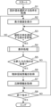
- FIG. 5 is a flowchart showing an example of the processing of the information processing device 10 shown in FIG. 1.
- the acquisition unit 111 acquires an instruction from a user to select a design drawing (step S1). In this case, a menu screen for selecting a design drawing is displayed on the display of the terminal device 30, and an instruction to select one design drawing from the menu screen is input.
- the input instruction is transmitted to the information processing device 10 via the network and received by the communication unit 13.
- the acquisition unit 111 acquires instructions via the communication unit 13. Since this instruction includes the blueprint ID, the acquisition unit 111 can acquire blueprint information indicating the instructed blueprint from among the blueprint information stored in the memory 12.
- the acquisition unit 111 displays the display screen G1 on the display of the terminal device 30 by transmitting a display instruction for the display screen G1 to the terminal device 30 via the communication unit 13 (step S2).
- the display instructions on the display screen G1 displayed by default include blueprint information indicating the blueprint selected in step S1 and photographing information corresponding to the latest photographing date and time. Therefore, as shown in FIG. 2, the display screen G1 displayed by default includes a blueprint selection icon 201, and a photographing point icon 202 and a trajectory 203 corresponding to the latest photographing date and time. At this point, one shooting point icon has not been determined, so the image information display field R1 and the annotation information display field R2 are blank.
- the acquisition unit 111 displays a display including a blueprint on which a photographing point icon 202 and a trajectory 203 corresponding to the selected photographing date and time are superimposed. Display screen G1 on the display.
- the acquisition unit 111 determines whether an instruction from the user to select a shooting date and time has been acquired (step S3).
- a menu screen for selecting the shooting date and time is displayed on the display of the terminal device 30.
- the user inputs an instruction to select one shooting date and time from the menu screen.
- the photographing date and time displayed on the menu screen is a representative value of the photographing date and time included in the photographing information stored in the memory 12.
- the input instruction is transmitted to the information processing device 10 via the network and received by the communication unit 13.
- the acquisition unit 111 acquires instructions via the communication unit 13.
- step S3 If an instruction to select a shooting date and time is input (YES in step S3), the process proceeds to step S4. If the instruction to select the shooting date and time is not input (NO in step S3), the process returns to step S2.
- the display process is a process of determining one shooting point icon by dragging and dropping the selection icon 201 on the blueprint, and displaying image information associated with the determined one shooting point icon in the image information display field R1. It is.
- the acquisition unit 111 determines whether an instruction to input an annotation has been acquired (step S5).
- the annotation input instruction is an instruction input when the user intends to input an annotation to the image information displayed in the image information display field R1. This instruction is input, for example, by selecting an annotation input instruction button (not shown) displayed on the display screen G1.
- the input instruction is transmitted to the information processing device 10 via the network and received by the communication unit 13.
- the acquisition unit 111 acquires instructions via the communication unit 13.
- the acquisition unit 111 acquires object area information (step S6).
- the object area information is input by performing an operation of moving and deforming the frame (not shown) in the image information display field R1 as described above.
- the input object area information is transmitted to the information processing device 10 via the network and received by the communication unit 13.
- the acquisition unit 111 acquires object area information via the communication unit 13.
- the acquisition unit 111 adds an object area ID to the acquired object area information and stores it in the memory 12 in association with the imaging ID. Thereby, the object area D1 is set as shown in FIG. 3.
- step S5 if an annotation input instruction has not been acquired (NO in step S5), the process proceeds to step S8.
- the acquisition unit 111 acquires annotation information (step S7).
- the annotation information is input by inputting the annotation C1 into the annotation information display field R2 and pressing a send button (not shown).
- the input annotation information is transmitted to the information processing device 10 via the network and received by the communication unit 13.
- the acquisition unit 111 acquires annotation information via the communication unit 13.
- the acquisition unit 111 stores the acquired annotation information in the memory 12 in association with the photographing ID and the object area ID.
- the acquisition unit 111 determines whether a termination instruction has been acquired (step S8).
- the termination instruction is an instruction to close the display screen G1 displayed in step S3. This instruction is input by pressing an end button (not shown) displayed on the display screen G1. If the termination instruction is obtained (YES in step S8), the process ends. If the termination instruction has not been obtained (NO in step S8), the process returns to step S3. In this case, the display on the display screen G1 is maintained.
- the termination instruction is transmitted to the information processing device 10 via the network and received by the communication unit 13.
- the acquisition unit 111 acquires the termination instruction via the communication unit 13.
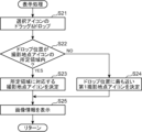
- FIG. 6 is a flowchart showing details of the display processing shown in FIG. 5.
- the acquisition unit 111 acquires an operation of dragging and dropping the selection icon 201 (step S21). This operation is performed by inputting an operation of dragging and dropping the selection icon 201 superimposed on the design drawing, as shown in FIG. Operation information indicating this operation is periodically transmitted from the terminal device 30 to the information processing device 10. This operation information includes the current position of the selection icon 201. Therefore, the determining unit 112 can obtain the current position of the selection icon 201 via the communication unit 13 and calculate the distance between the selection icon 201 and each shooting point icon 202.
- the determining unit 112 specifies up to a predetermined number (top 3) of photographing point icons 202 in descending order of distance from the selection icon 201, and sends a display instruction to the communication unit 13 to enlarge and display the specified photographing point icons 202.
- the information is transmitted to the terminal device 30 via the host computer. Further, when operation information indicating that the selection icon 201 is dropped is transmitted from the terminal device 30, the determining unit 112 detects the current position of the selection icon 201 at that time as the drop position.
- the determining unit 112 determines whether the drop position is within the predetermined area D2 of the shooting point icon 202 (step S22).
- the determining unit 112 determines the photography spot icon corresponding to the predetermined area D2 as one photography spot icon (step S23). ).
- the photography location icon 202(1) is determined as the first photography location icon.
- the determining unit 112 selects the first photographing point icon closest to the drop position as the first photographing point icon. (Step S24). In the example of FIG. 4, when the selection icon 201 is dropped at the drop position P1, the photographing point icon 202(2) is determined as the first photographing point icon.
- the output unit 113 displays the image information on the display screen G1 by transmitting the image information corresponding to the one shooting point icon determined in step S23 or S24 to the terminal device 30 via the communication unit 13. do.
- an image indicating image information corresponding to one shooting point icon is displayed in the image information display column R1.
- annotation information is transmitted to the terminal device 30 via the communication unit 13 in addition to the image information.
- the annotation C1 indicated by the annotation information corresponding to the image information displayed in the image information display field R1 is displayed in the annotation information display field R2.
- the annotation information display column R2 becomes blank.
- one photographing point icon is determined based on the drop position of the selection icon 201 and the position of each photographing point icon 202.
- Image information corresponding to the one determined shooting point icon is displayed. This image information indicates an image photographed at the photographing point. This allows the user to remotely check the status of the construction site at the shooting point. Therefore, a user viewing the image information can remotely check the status of the construction site indicated by the blueprint in detail.
- the bird's eye view may be a floor plan showing the floor plan of the house.
- the present disclosure can be applied to remodeling the interior of a house.
- the bird's eye view may be a layout diagram that simply shows the floor plan of the house.
- annotation information is associated with the object region D1, if the object region D1 is not set, it may be associated with the image information.
- one shooting point icon is determined by dragging and dropping the selection icon 201, but this is just an example.
- a shooting point icon may be determined. For example, if the click position of the mouse pointer is within the predetermined area D2 with respect to any of the photographing point icons 202, the photographing point icon 202 corresponding to the clicked predetermined area D2 is determined as one photographing point icon. For example, if the click position of the mouse pointer is outside the predetermined area D2 for any of the photographing point icons 202, the photographing point icon 202 closest to the click position is determined as the one photographing point icon.
- a construction site is exemplified as a site, but the present disclosure is not limited to this, and includes a manufacturing site, a logistics site, a distribution site, farmland, a civil engineering site, a retail site, an office, a hospital, a commercial facility, A nursing home or the like may also be employed as a site.
- the present disclosure is useful for managing construction sites because the status of the construction site can be checked remotely.
Landscapes
- Engineering & Computer Science (AREA)
- Theoretical Computer Science (AREA)
- General Engineering & Computer Science (AREA)
- Physics & Mathematics (AREA)
- General Physics & Mathematics (AREA)
- Human Computer Interaction (AREA)
- User Interface Of Digital Computer (AREA)
Abstract
Description
建築現場の課題として、具体的な指示が作業員に伝わらない、その指示の説明に時間がかかるといったコミュニケーション上の課題や建築現場全体を回るのに人手が必要、建築現場への移動に時間がかかるといった建築現場の確認上の課題などがある。
図1は、本開示の実施の形態における情報処理システム1の構成の一例を示すブロック図である。情報処理システム1は、情報処理装置10、撮影装置20、及び端末装置30を含む。情報処理装置10、撮影装置20、及び端末装置30は、ネットワークを介して通信可能に接続されている。ネットワークの一例はインターネットである。情報処理装置10は、例えば1又は複数のコンピュータで構成されたクラウドサーバである。但し、これは一例であり、情報処理装置10は、エッジサーバで構成されもよいし、端末装置30に実装されてもよい。
Claims (11)
- コンピュータにおける情報処理方法であって、
端末装置のディスプレイに、鳥瞰図を表示し、
前記鳥瞰図に、撮影地点を示す複数の撮影地点アイコンと、前記鳥瞰図の任意の位置を選択するための選択アイコンと、を表示し、
前記選択アイコンは前記鳥瞰図上を移動可能に構成され、
前記複数の撮影地点アイコンには撮影地点で撮影された画像を示す画像情報が対応づけられ、
前記選択アイコンの移動完了位置を検知し、前記移動完了位置と各撮影地点アイコンの位置とに基づいて1の撮影地点アイコンを決定し、
前記1の撮影地点アイコンに対応づけられた画像情報を前記ディスプレイに出力する、
情報処理方法。 - 前記複数の撮影地点アイコンは、注釈情報が対応づけられた第1撮影地点アイコンを含み、
前記決定において、前記移動完了位置が前記複数の撮影地点アイコンのそれぞれの位置から所定の領域外に位置する場合、前記移動完了位置に最も近い第1撮影地点アイコンを前記1の撮影地点アイコンとして決定し、
前記出力において、選択された第1撮影地点アイコンに対応づけられた画像情報及び注釈情報を前記ディスプレイに出力する、
請求項1記載の情報処理方法。 - 前記決定において、前記移動完了位置がいずれかの撮影地点アイコンの位置から所定領域内に位置する場合、当該撮影地点アイコンを前記1の撮影地点アイコンとして決定する、
請求項1記載の情報処理方法。 - さらに、移動中の前記選択アイコンの現在位置を検知し、前記現在位置から近い順に所定数の撮影地点アイコンを決定し、前記所定数の撮影地点アイコンを強調表示する、
請求項1記載の情報処理方法。 - 前記強調表示は、前記所定数の撮影地点アイコンのそれぞれを、所定領域を示すサイズに拡大表示することを含む、
請求項4記載の情報処理方法。 - 前記複数の撮影地点アイコンは、注釈情報が対応づけられた第1撮影地点アイコンを含み、前記第1撮影地点アイコンは、注釈アイコンが対応づけて表示され、
前記強調表示は、前記所定数の撮影地点アイコンの中に前記第1撮影地点アイコンが含まれている場合、当該第1撮影地点アイコンに対応づけられた注釈アイコンを拡大表示することを含む、
請求項4記載の情報処理方法。 - 前記鳥瞰図は、設計図であり、
前記画像情報は、前記設計図が表す施工現場で全方位カメラにより撮影された画像を示す、
請求項1又は2記載の情報処理方法。 - 前記選択アイコンの移動はドラッグであり、
前記移動完了位置は前記選択アイコンのドロップ位置である、
請求項1又は2記載の情報処理方法。 - 前記画像情報には、前記画像情報が示す画像に含まれる物体を示す物体領域が設定され、
前記注釈情報は、前記物体に関連する注釈を示す、
請求項2記載の情報処理方法。 - プロセッサを含む情報処理装置であって、
前記プロセッサは、
端末装置のディスプレイに、鳥瞰図を表示し、
前記鳥瞰図に、撮影地点を示す複数の撮影地点アイコンと、前記鳥瞰図の任意の位置を選択するための選択アイコンと、を表示し、
前記選択アイコンは前記鳥瞰図を移動可能に構成され、
前記複数の撮影地点アイコンには撮影地点で撮影された画像情報が対応づけられ、
前記選択アイコンの移動完了位置を検知し、前記移動完了位置と各撮影地点アイコンの位置とに基づいて1の撮影地点アイコンを決定し、
前記1の撮影地点アイコンに対応づけられた画像情報を前記ディスプレイに出力する、処理を実行する、
情報処理装置。 - 請求項1又は2記載の情報処理方法をコンピュータに実行させるための情報処理プログラム。
Priority Applications (3)
| Application Number | Priority Date | Filing Date | Title |
|---|---|---|---|
| CN202380038125.0A CN119053982A (zh) | 2022-05-17 | 2023-05-16 | 信息处理方法、信息处理装置以及信息处理程序 |
| JP2024521940A JPWO2023224030A1 (ja) | 2022-05-17 | 2023-05-16 | |
| US18/948,120 US20250068296A1 (en) | 2022-05-17 | 2024-11-14 | Information processing method, information processing device, and non-transitory computer readable recording medium |
Applications Claiming Priority (4)
| Application Number | Priority Date | Filing Date | Title |
|---|---|---|---|
| US202263342785P | 2022-05-17 | 2022-05-17 | |
| US63/342,785 | 2022-05-17 | ||
| JP2023056542 | 2023-03-30 | ||
| JP2023-056542 | 2023-03-30 |
Related Child Applications (1)
| Application Number | Title | Priority Date | Filing Date |
|---|---|---|---|
| US18/948,120 Continuation US20250068296A1 (en) | 2022-05-17 | 2024-11-14 | Information processing method, information processing device, and non-transitory computer readable recording medium |
Publications (1)
| Publication Number | Publication Date |
|---|---|
| WO2023224030A1 true WO2023224030A1 (ja) | 2023-11-23 |
Family
ID=88835572
Family Applications (1)
| Application Number | Title | Priority Date | Filing Date |
|---|---|---|---|
| PCT/JP2023/018245 Ceased WO2023224030A1 (ja) | 2022-05-17 | 2023-05-16 | 情報処理方法、情報処理装置、及び情報処理プログラム |
Country Status (4)
| Country | Link |
|---|---|
| US (1) | US20250068296A1 (ja) |
| JP (1) | JPWO2023224030A1 (ja) |
| CN (1) | CN119053982A (ja) |
| WO (1) | WO2023224030A1 (ja) |
Citations (1)
| Publication number | Priority date | Publication date | Assignee | Title |
|---|---|---|---|---|
| JPH1131063A (ja) * | 1997-07-10 | 1999-02-02 | Hitachi Ltd | アイコン自動拡大方法 |
-
2023
- 2023-05-16 JP JP2024521940A patent/JPWO2023224030A1/ja active Pending
- 2023-05-16 WO PCT/JP2023/018245 patent/WO2023224030A1/ja not_active Ceased
- 2023-05-16 CN CN202380038125.0A patent/CN119053982A/zh active Pending
-
2024
- 2024-11-14 US US18/948,120 patent/US20250068296A1/en active Pending
Patent Citations (1)
| Publication number | Priority date | Publication date | Assignee | Title |
|---|---|---|---|---|
| JPH1131063A (ja) * | 1997-07-10 | 1999-02-02 | Hitachi Ltd | アイコン自動拡大方法 |
Non-Patent Citations (2)
| Title |
|---|
| "BYOD introduction guide Thorough use of smartphones and tablets", 22 November 2013, NIKKEI BP, ISBN: 978-4-8222-1094-6, article "Streamline construction work with iPad apps. Do not apply MDM to privately owned devices", pages: 54 - 55, XP009550451 * |
| "Mediax MOOK940 Revised edition A book that perfectly understands Google services", 30 July 2023, MEDIAX CO., LTD., ISBN: 978-4-86674-300-4, article "Basic screen of Google Maps", pages: 54 - 59, XP009550452 * |
Also Published As
| Publication number | Publication date |
|---|---|
| CN119053982A (zh) | 2024-11-29 |
| JPWO2023224030A1 (ja) | 2023-11-23 |
| US20250068296A1 (en) | 2025-02-27 |
Similar Documents
| Publication | Publication Date | Title |
|---|---|---|
| JPWO2014021004A1 (ja) | 画像処理システム、画像処理方法、及びプログラム | |
| US9239892B2 (en) | X-ray vision for buildings | |
| US11048345B2 (en) | Image processing device and image processing method | |
| JP2021018710A (ja) | 現場連携システムおよび管理装置 | |
| JP6132811B2 (ja) | プログラム及び情報処理装置 | |
| JP5525497B2 (ja) | プラント作業支援装置およびプラント作業支援方法 | |
| WO2023224030A1 (ja) | 情報処理方法、情報処理装置、及び情報処理プログラム | |
| WO2023224031A1 (ja) | 情報処理方法、情報処理装置、及び情報処理プログラム | |
| US20250069285A1 (en) | Information processing method, information processing device, and non-transitory computer readable recording medium | |
| US12596511B2 (en) | Information processing method, information processing device, and non-transitory computer readable recording medium | |
| US20230125097A1 (en) | Photography support device and method, and computer-readable storage medium | |
| CN107102794B (zh) | 操作处理方法及装置 | |
| CN114964251B (zh) | 一种导航方法、装置及其相关设备和存储介质 | |
| JP7836439B1 (ja) | 大規模屋外施設用の点検支援方法およびプログラム | |
| KR102816246B1 (ko) | 실사 지도를 이용한 부동산 정보 표시 방법 및 장치 | |
| WO2025094964A1 (ja) | 情報処理方法、情報処理装置、及び情報処理プログラム | |
| US12051218B2 (en) | Remote support system, terminal device, and remote device | |
| WO2025094911A1 (ja) | 情報処理方法、情報処理装置、及び情報処理プログラム | |
| US20230128950A1 (en) | Photography position management device and method, and computer-readable storage medium | |
| JP2015069445A (ja) | 映像出力装置、映像出力方法、及びプログラム | |
| JP5493581B2 (ja) | 情報処理システム、情報処理装置、情報管理装置及びプログラム | |
| WO2025094793A1 (ja) | 情報処理方法、情報処理装置、及び情報処理プログラム | |
| JP6670918B2 (ja) | 生成装置、生成方法及び生成プログラム | |
| WO2025095022A1 (ja) | 情報処理方法、情報処理装置、及び情報処理プログラム | |
| WO2025094932A1 (ja) | 情報処理方法、情報処理装置、及び情報処理プログラム |
Legal Events
| Date | Code | Title | Description |
|---|---|---|---|
| 121 | Ep: the epo has been informed by wipo that ep was designated in this application |
Ref document number: 23807632 Country of ref document: EP Kind code of ref document: A1 |
|
| WWE | Wipo information: entry into national phase |
Ref document number: 202380038125.0 Country of ref document: CN Ref document number: 2024521940 Country of ref document: JP |
|
| NENP | Non-entry into the national phase |
Ref country code: DE |
|
| 122 | Ep: pct application non-entry in european phase |
Ref document number: 23807632 Country of ref document: EP Kind code of ref document: A1 |