WO2023224027A1 - 貯湯式給湯機 - Google Patents
貯湯式給湯機 Download PDFInfo
- Publication number
- WO2023224027A1 WO2023224027A1 PCT/JP2023/018232 JP2023018232W WO2023224027A1 WO 2023224027 A1 WO2023224027 A1 WO 2023224027A1 JP 2023018232 W JP2023018232 W JP 2023018232W WO 2023224027 A1 WO2023224027 A1 WO 2023224027A1
- Authority
- WO
- WIPO (PCT)
- Prior art keywords
- hot water
- water storage
- storage tank
- outlet
- heat exchanger
- Prior art date
- Legal status (The legal status is an assumption and is not a legal conclusion. Google has not performed a legal analysis and makes no representation as to the accuracy of the status listed.)
- Ceased
Links
Images



Classifications
-
- F—MECHANICAL ENGINEERING; LIGHTING; HEATING; WEAPONS; BLASTING
- F24—HEATING; RANGES; VENTILATING
- F24H—FLUID HEATERS, e.g. WATER OR AIR HEATERS, HAVING HEAT-GENERATING MEANS, e.g. HEAT PUMPS, IN GENERAL
- F24H1/00—Water heaters, e.g. boilers, continuous-flow heaters or water-storage heaters
- F24H1/18—Water-storage heaters
-
- F—MECHANICAL ENGINEERING; LIGHTING; HEATING; WEAPONS; BLASTING
- F24—HEATING; RANGES; VENTILATING
- F24H—FLUID HEATERS, e.g. WATER OR AIR HEATERS, HAVING HEAT-GENERATING MEANS, e.g. HEAT PUMPS, IN GENERAL
- F24H9/00—Details
Definitions
- the present disclosure relates to a hot water storage type water heater.
- Patent Document 1 discloses a hot water storage type water heater that includes a heating heat exchanger that heats hot water and a hot water storage tank that stores the hot water heated by the heating heat exchanger.
- This hot water storage type water heater heats the low-temperature hot water stored in the lower part of the hot water storage tank by flowing it into the heating heat exchanger through the outflow piping, and then passes the heated hot water through the inflow piping. Let it flow into the inside of the hot water storage tank.
- the high-temperature hot water is discharged toward the lower part of the hot water storage tank from an opening that the inflow pipe has and is arranged at an intermediate portion in the height direction of the hot water storage tank.
- the discharged high-temperature hot water flows toward the bottom of the hot water storage tank due to inertia, and then flows toward the top of the hot water storage tank due to buoyancy.
- the high-temperature hot water flows throughout the interior of the hot water tank while heating the surrounding low-temperature hot water, and the temperature of the entire hot water stored in the hot water storage tank increases.
- the opening of the outflow pipe through which hot water flows from the hot water storage tank is located below the opening of the inflow pipe through which hot water flows out to the hot water storage tank. Therefore, after the high-temperature hot water heated by the heating heat exchanger is discharged from the opening of the inflow piping toward the bottom of the hot water storage tank, the opening of the outflow piping is discharged without heating the surrounding low-temperature hot water. There is a risk that a short cycle may occur where the heat flows through the heating heat exchanger and is heated again. When a short cycle occurs, the temperature of the hot water flowing into the heating heat exchanger increases, the boiling efficiency decreases, and the energy saving performance decreases.
- the present disclosure has been made in view of the above-mentioned circumstances, and aims to provide a hot water storage type water heater with high boiling efficiency.
- a hot water storage type water heater includes a hot water storage tank that stores hot water, a heating heat exchanger that heats the hot water stored in the hot water storage tank, and a heating heat exchanger that heats the hot water stored in the hot water storage tank. It includes an outflow pipe that supplies hot water to the tank, and an inflow pipe that supplies hot water heated by the heating heat exchanger to the hot water storage tank.
- the hot water storage tank has a cylindrical tank body and a lower head plate joined to the lower end of the tank body.
- An outflow port is provided at the end of the outflow pipe inside the hot water storage tank.
- An inlet is provided at the end of the inflow pipe inside the hot water storage tank.
- the outlet is located above the joint between the tank body and the lower mirror plate.
- the inflow pipe discharges hot water downward into the hot water storage tank from the inlet.
- the vertical distance between the outlet and the joint is larger than the vertical distance between the lower end of the lower end plate and the joint.
- the high-temperature hot water heated by the heating heat exchanger has a long path from when it flows into the hot water storage tank through the inlet until it reaches the outlet. Therefore, the occurrence of a short cycle in which the hot water flowing into the hot water storage tank flows out to the heating heat exchanger without heating the surrounding hot water is suppressed. Therefore, high boiling efficiency can be ensured.
- Configuration diagram of a hot water storage type water heater according to Embodiment 1 of the present disclosure A vertical cross-sectional view of a hot water storage tank according to Embodiment 1 of the present disclosure A diagram showing an example of the flow of hot water flowing into the hot water storage tank according to Embodiment 1 of the present disclosure A diagram showing an example of the flow of hot water flowing into a hot water storage tank according to Embodiment 2 of the present disclosure A cross-sectional view of a hot water storage tank according to Embodiment 3 of the present disclosure A diagram showing an example of the flow of hot water flowing into a hot water storage tank according to Embodiment 3 of the present disclosure Configuration diagram of a hot water storage type water heater according to Embodiment 4 of the present disclosure
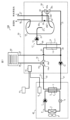
- the hot water storage type water heater 100 shown in FIG. 1 includes a heat pump unit 40 that heats hot water, a tank unit 50 that has a hot water storage tank 10 that stores the hot water heated by the heat pump unit 40, and operations of the heat pump unit 40 and the tank unit 50.
- a control device 70 is provided to supply hot water stored in the hot water storage tank 10 to a hot water supply destination such as a shower or a faucet.
- the heat pump unit 40 and the tank unit 50 are connected to each other via piping 21 and piping 22.
- the tank unit 50 is connected via piping 34 and piping 35 to a heating device 60 that is a hot water heating device such as a floor heating device or a hot water room heater.
- the heat pump unit 40 includes a compressor 1 that compresses a refrigerant such as carbon dioxide, R140A, and R32, a pressure reducing device 2 that reduces the pressure of the refrigerant, a heat exchanger 3 that functions as an evaporator, and supplies air to the heat exchanger 3.
- a first heating heat exchanger 5 that functions as a condenser, and a control device 6 that controls the operations of the compressor 1, the pressure reducing device 2, and the blower 4.
- the compressor 1 compresses the refrigerant and changes it into a high-temperature, high-pressure refrigerant.
- the first heating heat exchanger 5 includes a first heat medium flow path 7 through which a heat medium such as hot water and antifreeze flows, and a refrigerant flow path 8 through which a refrigerant flows, and a compressor that flows through the refrigerant flow path 8.
- the high-temperature, high-pressure refrigerant discharged from the first heat medium flow path 7 exchanges heat with the low-temperature heat medium flowing through the first heat medium flow path 7, thereby heating the heat medium.
- the pressure reducing device 2 is an expansion valve, which applies heat to the heat medium in the first heating heat exchanger 5 to reduce the pressure of the refrigerant whose temperature has dropped, thereby changing it into a low-temperature, low-pressure refrigerant.
- the heat exchanger 3 causes the low-temperature, low-pressure refrigerant discharged from the pressure reducing device 2 to absorb heat from the air, thereby heating the refrigerant.
- the control device 6 communicates with the control device 15 and the control device 70, and controls the operations of the compressor 1, the pressure reducing device 2, and the blower 4 according to the control by the control device 70.
- the compressor 1, the pressure reducing device 2, the heat exchanger 3, and the first heating heat exchanger 5 are connected in a ring through piping through which refrigerant flows, forming a refrigerant circuit 9 in which the refrigerant circulates.
- the refrigerant circuit 9 functions as a heat pump cycle that heats hot water.
- the hot water storage tank 10 included in the tank unit 50 is connected to a hot water supply destination via a hot water outlet pipe 36.
- the hot water outlet pipe 36 supplies hot water stored in the hot water storage tank 10 to a hot water supply destination.
- the hot water storage tank 10 is connected to a city water supply source via a water supply pipe 37.
- city water is supplied from the city water supply source to the hot water storage tank 10 via the water supply pipe 37.
- the tank unit 50 includes a second heating heat exchanger 11 that heats hot water stored in the hot water storage tank 10, a first pump 12 that transports a heat medium, and a second The operation of the second pump 13 that supplies the heat medium to the heating heat exchanger 11, the flow path switching device 14 that switches the flow path of the heat medium, the first pump 12, the second pump 13, and the flow path switching device 14.
- a control device 15 is provided.
- the second heating heat exchanger 11 is an example of a heating heat exchanger.
- the second heating heat exchanger 11 exchanges heat between the heat medium heated by the first heating heat exchanger 5 and the hot water supplied from the hot water storage tank 10 to boil the hot water.
- the first pump 12 causes the heat medium to flow through the first heating heat exchanger 5 and the second heating heat exchanger 11 .
- the second pump 13 sends hot water stored inside the hot water storage tank 10 to the second heating heat exchanger 11 .
- the control device 15 communicates with the control device 6 and the control device 70, and controls the operations of the first pump 12, the second pump 13, and the flow path switching device 14 according to the control by the control device 70.
- the first heating heat exchanger 5, the flow path switching device 14, the second heating heat exchanger 11, and the first pump 12 form a first heat transfer circuit 16 through which the heat medium flows.
- the second pump 13, the hot water storage tank 10, and the second heating heat exchanger 11 form a second heat transfer circuit 17 through which hot water flows.
- the heat medium flowing through the first heat transfer circuit 16 receives heat from the refrigerant flowing through the refrigerant circuit 9 and gives heat to the hot water flowing through the second heat transfer circuit 17 .
- the second heating heat exchanger 11 exchanges heat between the heat medium flowing through the first heat transfer circuit 16 and hot water flowing through the second heat transfer circuit 17 .
- the second heating heat exchanger 11 has a second heat medium flow path 18 through which the heat medium flowing through the first heat transfer circuit 16 passes, and a second heat medium flow path 18 through which hot water flows through the second heat transfer circuit 17.
- a third heat medium flow path 19 is provided, and the heat medium flowing through the second heat medium flow path 18 is caused to exchange heat with hot water flowing through the third heat medium flow path 19.
- the flow path switching device 14 includes an inlet 14a connected to the first heat medium flow path 7, and an outlet 14b connected to the second heat medium flow path 18 of the second heating heat exchanger 11. An outlet 14c connected to the heating device 60.
- the flow path switching device 14 switches the heat medium flowing through the first heat transfer circuit 16 by closing one of the outlets 14b and 14c and opening the other of the outlets 14b and 14c under the control of the control device 15. Switch the flow path.
- the first heat transfer circuit 16 connects these to each other in addition to the first heating heat exchanger 5, flow path switching device 14, second heating heat exchanger 11, and first pump 12. It includes pipes 21 to 24, and pipes 34 and 35 that interconnect the flow path switching device 14, the first pump 12, and the heating device 60.
- the pipe 21 connects the discharge side of the first pump 12 and the first heat medium flow path 7 of the first heating heat exchanger 5.
- the pipe 22 connects the first heat medium flow path 7 and the inlet 14a of the flow path switching device 14.
- the pipe 23 connects the outlet 14b of the flow path switching device 14 and the second heat medium flow path 18 included in the second heating heat exchanger 11.
- Piping 24 connects second heat medium flow path 18 and the suction side of first pump 12 .
- the pipe 34 connects the outlet 14c of the flow path switching device 14 and the heating device 60.
- the heat medium of the first heat transfer circuit 16 discharged from the outlet 14c of the flow path switching device 14 flows into the heating device 60 via the pipe 34.
- Piping 35 connects heating device 60 and the suction side of first pump 12 .
- the heat medium of the first heat transfer circuit 16 flowing out from the heating device 60 flows into the first pump 12 via the pipe 35.
- the second heat transfer circuit 17 transfers the hot water heated by the second heating heat exchanger 11 to the second heating heat exchanger 11.
- An inflow pipe 27 that supplies hot water from the heating heat exchanger 11 to the hot water storage tank 10 and an outflow pipe 28 that supplies hot water stored in the hot water storage tank 10 from the hot water storage tank 10 to the second heating heat exchanger 11.
- the inflow pipe 27 connects the discharge side of the second pump 13 and the hot water storage tank 10.
- the outflow pipe 28 connects the hot water storage tank 10 and the third heat medium flow path 19 included in the second heating heat exchanger 11 .
- the hot water storage tank 10 is made of a material such as metal or resin, and stores hot water heated by the second heating heat exchanger 11.
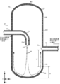
- FIG. 2 is a longitudinal cross-sectional view of the hot water storage tank 10 taken along a cut plane that includes the axis of the tank body 10A and is parallel to the vertical direction G.
- the hot water storage tank 10 includes a cylindrical tank body 10A, a hemispherical or bowl-shaped lower end plate 10B that is convex vertically downward and is joined to the lower end of the tank body 10A, and a tank body. It includes a hemispherical or bowl-shaped upper mirror plate 10C joined to the upper end of the portion 10A.
- the lower end of the tank body 10A and the lower mirror plate 10B are joined by welding or adhesive at a first joint 10D.
- the first joint 10D is an example of a joint.
- the upper end of the tank body 10A and the upper mirror plate 10C are joined by welding or adhesive at a second joint 10E.
- An inflow pipe 27 and an outflow pipe 28 are connected to the hot water storage tank 10.
- the hot water tap piping 36 and the water supply piping 37 are not illustrated.
- an XYZ orthogonal coordinate system shown in FIG. 2 will be set.
- the Z axis is set parallel to the vertical direction G.
- the inflow pipe 27 and the outflow pipe 28 are included in a plane parallel to the Z-axis, the X-axis is set parallel to this plane, and the Y-axis is set perpendicular to this plane.
- the X-axis direction corresponds to the left-right direction
- the Y-axis direction corresponds to the front-back direction
- the Z-axis direction corresponds to the up-down direction.
- the Z-axis direction also corresponds to the height direction of the hot water storage tank 10.
- the inflow pipe 27 is inserted into the tank body 10A at the middle part in the height direction of the hot water storage tank 10 and extends inside the hot water storage tank 10.
- the inflow pipe 27 has a horizontal portion 27a extending parallel to the horizontal direction, a vertical portion 27b provided downstream from the horizontal portion 27a and extending parallel to the vertical direction G, and a downstream end of the horizontal portion 27a and the vertical portion 27b.
- the upper end of the vertical portion 27b is located below the downstream end of the horizontal portion 27a.
- An inlet 27c through which hot water flows into the hot water storage tank 10 is provided at the lower end of the vertical portion 27b, which is the end of the inflow pipe 27 inside the hot water storage tank 10. The inlet 27c opens downward.
- the position of the inlet 27c in the vertical direction G is located lower than the position of the second joint 10E in the vertical direction G.
- the hot water flowing out from the second heating heat exchanger 11 passes through the horizontal portion 27a, the curved portion 27d, and the vertical portion 27b of the inflow pipe 27 in this order, and is discharged downward into the hot water storage tank 10 from the inflow port 27c.
- the axis of the inlet 27c coincides with the axis of the lower mirror plate 10B.
- the axis of the hemispherical or bowl-shaped lower head plate 10B passes through the lower end of the lower head plate 10B. Thereby, the hot water that has passed through the inflow pipe 27 is discharged from the inflow port 27c toward the lower end of the lower mirror plate 10B.
- the outflow pipe 28 is connected to a position below the position where the inflow pipe 27 of the tank body 10A is connected.
- the outflow pipe 28 does not extend inside the hot water storage tank 10, and the upstream end of the outflow pipe 28 is joined to the inner wall of the tank body 10A.
- An outflow port 28a through which hot water flows out from the hot water storage tank 10 is provided at an upstream end of the outflow pipe 28, which is an end of the outflow pipe 28 inside the hot water storage tank 10.
- the outlet 28a opens horizontally. Hot water in the hot water storage tank 10 flows out from the outlet 28a, passes through the outflow pipe 28, and flows into the second heating heat exchanger 11.
- the inlet 27c is located above the outlet 28a.
- the outflow port 28a is arranged at a position shifted from the direction of hot water discharge from the inflow port 27c, avoiding the direction of hot water discharge.
- the horizontal distance between the inlet 27c and the outlet 28a is such that hot water discharged from the inlet 27c is prevented from directly flowing into the outlet 28a.
- the horizontal distance between the inlet 27c and the outlet 28a is set to a value larger than the distance over which the hot water discharged from the inlet 27c spreads in the horizontal direction before reaching the lower mirror plate 10B.
- the outlet 28a is located above the first joint 10D, which is the joint between the tank body 10A and the lower mirror plate 10B.
- the axis of the outlet 28a and the axis of the tank body 10A are included in a plane that includes the axis of the inlet 27c and is parallel to the vertical direction G.
- the vertical distance L1 between the outlet 28a and the first joint 10D is larger than the vertical distance L2 between the lower end of the lower mirror plate 10B and the first joint 10D.
- each temperature sensor is electrically connected to the control device 70, detects the temperature of hot water inside the hot water storage tank 10 at the position where each temperature sensor is installed, and sends an output signal indicating the detection result to the control device 70. do.
- the control device 70 includes a processor that executes various processes and a memory that stores data and programs.
- the processor of the control device 70 functions as an operation control means that controls the operations of the heat pump unit 40 and the tank unit 50 by executing a program stored in the memory.
- the control device 70 causes the control device 6 to control the operation of the heat pump unit 40 and the control device 15 to control the operation of the tank unit 50 by transmitting control signals to the control device 6 and the control device 15.
- the control device 70 constantly monitors the amount of remaining hot water and the amount of heat storage inside the hot water storage tank 10.
- the control device 70 detects the temperature distribution along the vertical direction of the hot water stored in the hot water storage tank 10 based on the output signals received from the five temperature sensors described above, thereby controlling the amount of remaining hot water and heat storage inside the hot water storage tank 10. Detect amount.
- the control device 70 controls whether the hot water storage type A water heater 100 is caused to perform a boiling operation for heating hot water stored in a hot water storage tank 10.
- the refrigerant flowing through the refrigerant circuit 9 heats the heat medium flowing through the first heat transfer circuit 16, and the heated heat medium flowing through the first heat transfer circuit 16 heats the heat medium flowing through the second heat transfer circuit 16. Heat the hot water flowing through 17.
- the hot water flowing through the heated second heat transfer circuit 17 is stored in the hot water storage tank 10.
- the refrigerant in the refrigerant circuit 9, the refrigerant is compressed and discharged by the compressor 1, flows into the refrigerant passage 8 of the first heating heat exchanger 5, and in the process of passing through the refrigerant passage 8, the refrigerant is compressed and discharged by the compressor 1.
- the heat medium of the first heat transfer circuit 16 flowing through the first heat medium flow path 7 is heated.
- the refrigerant liquefies while passing through the refrigerant flow path 8 .
- the refrigerant flowing out from the refrigerant flow path 8 flows into the pressure reducing device 2, is depressurized by the pressure reducing device 2, and changes into a gas-liquid two-phase state.
- the refrigerant flowing out of the pressure reducing device 2 flows into the heat exchanger 3 and absorbs heat from the air around the heat pump unit 40 .
- the refrigerant vaporizes while passing through the heat exchanger 3.
- the refrigerant flowing out from the heat exchanger 3 returns to the compressor 1.
- the heat medium is pressurized and discharged by the first pump 12, and is sent to the first heat medium flow path 7 of the first heating heat exchanger 5 via piping 21.
- the refrigerant is heated by the refrigerant of the refrigerant circuit 9 flowing through the refrigerant flow path 8 .
- the heat medium flowing out of the first heat medium flow path 7 flows into the inlet 14a of the flow path switching device 14 via the pipe 22.
- the flow path switching device 14 closes the outlet 14c and opens the outlet 14b under the control of the control device 15.
- the heat medium that has flowed into the inlet 14a of the flow path switching device 14 flows out from the outlet 14b.
- the heat medium flowing out from the outlet 14b flows into the second heat medium flow path 18 of the second heating heat exchanger 11 via the pipe 23, and in the process of passing through the second heat medium flow path 18, the heat medium flows into the second heat medium flow path 18 of the second heat exchanger 11 for heating.
- the hot water flowing through the heat medium flow path 19 of No. 3 is heated.
- the heat medium flowing out from the second heat medium flow path 18 returns to the first pump 12 via the piping 24.
- the hot water stored in the hot water storage tank 10 flows into the third heat medium flow path 19 of the second heating heat exchanger 11 via the outflow pipe 28, and flows into the third heat medium flow path 19 of the second heating heat exchanger 11.
- it is heated by the heat medium of the first heat transfer circuit 16 flowing through the second heat medium flow path 18.
- the hot water flowing out from the third heat medium flow path 19 flows into the second pump 13 via the pipe 26.
- the hot water that has flowed into the second pump 13 is pressurized and discharged by the second pump 13, and flows into the hot water storage tank 10 via the inflow pipe 27.
- the hot water flowing into the hot water storage tank 10 heats the hot water stored in the hot water storage tank 10.
- FIG. 3 is a diagram showing an example of the flow of hot water flowing into the hot water storage tank 10.
- FIG. 3 shows a longitudinal section of the hot water storage tank 10 taken along a cut plane that includes the axis of the tank body 10A and is parallel to the vertical direction G.
- Arrow AA in FIG. 3 indicates the flow of hot water.
- the inflow pipe 27 discharges hot water downward into the hot water storage tank 10 from an inflow port 27c. The discharged hot water flows downward due to inertia, collides with or contacts the lower head plate 10B of the hot water storage tank 10, and then flows upward along the lower head plate 10B and the inner wall of the tank body 10A due to buoyancy.
- the hot water that flows upward and reaches the outlet 28a of the outlet pipe 28 flows out from the outlet 28a and flows into the second heating heat exchanger 11 via the outlet pipe 28.
- the hot water that has flowed into the hot water storage tank 10 via the inflow pipe 27 is high-temperature hot water that has been heated by the second heating heat exchanger 11, and in the process of flowing inside the hot water storage tank 10 along the above-mentioned path. Heats the surrounding low-temperature water.
- the vertical distance L1 between the outlet 28a and the first joint 10D is larger than the vertical distance L2 between the lower end of the lower mirror plate 10B and the first joint 10D.
- the high-temperature hot water heated by the second heating heat exchanger 11 has a long path from flowing into the hot water storage tank 10 through the inlet 27c until reaching the outlet 28a. It takes a long time for high-temperature hot water to flow into the hot water storage tank 10 until it flows out to the second heating heat exchanger 11. That is, according to such a configuration, it takes a long time to heat the surrounding low-temperature hot water from when the high-temperature hot water flows into the hot water storage tank 10 until it flows out to the second heating heat exchanger 11.
- the inlet 27c and the outlet 28a are arranged in a positional relationship that prevents hot water discharged from the inlet 27c from directly flowing into the outlet 28a. Therefore, the occurrence of short cycles is suppressed.
- the position and opening direction of the outlet 28a are not limited to the positions and opening directions shown in FIGS. 2 and 3, and can be set arbitrarily.
- the inflow pipe 27 and the outflow pipe 28 are arranged on the same plane that includes the axis of the tank body 10A, but this is only an example;
- the outflow pipes 28 may be configured to extend on different planes.
- the position and opening direction of the outflow port 28a are shifted from the position and opening direction where hot water discharged from the inflow port 27c is prevented from directly flowing into the outflow port 28a, for example, from the direction in which hot water is discharged from the inflow port 27c. It is preferable to set the position and the opening direction that intersects with the discharge direction.
- the outflow port 28a may be arranged to avoid an area in which the hot water discharged from the inflow port 27c diffuses in the horizontal direction before reaching the height of the outflow pipe 28, as determined by experiment or simulation. It is preferable that the hot water discharged from the inlet 27c is disposed so as to avoid an area where hot water is diffused before reaching the lower mirror plate 10B.
- the arrangement position of the outlet 28a at which the amount of hot water directly flowing into the outlet 28a is negligibly small may be determined by experiment or simulation.
- the ratio of the amount of hot water directly flowing into the outlet 28a to the amount of hot water discharged from the inlet 27c is equal to the reference value.
- One example is 15% or less, more preferably 10% or less.
- the above-mentioned reference value is not limited to 15%.
- the reference value is preferably 5% or less. This suppresses hot water discharged from the inlet 27c from directly flowing into the outlet 28a.
- the outlet 28a opens in the wall of the hot water storage tank 10.
- the present disclosure is not limited to this example.
- the second embodiment, in which the outflow pipe 28 extends into the hot water storage tank 10 and the outflow port 28a opens upward, will be described below, focusing on the differences from the first embodiment.
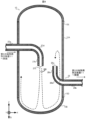
- FIG. 4 is a diagram showing an example of the flow of hot water flowing into the hot water storage tank 10 according to the second embodiment.
- FIG. 4 shows a longitudinal section of the hot water storage tank 10 according to the present embodiment, which is cut along a cut plane that includes the axis of the tank body 10A and is parallel to the vertical direction G.
- the outflow pipe 28 according to the present embodiment extends into the hot water storage tank 10 through a through hole provided in the middle part of the hot water storage tank 10 in the height direction.
- the outflow pipe 28 has a horizontal part 28b extending parallel to the horizontal direction, a vertical part 28c provided upstream of the horizontal part 28b and extending parallel to the vertical direction G, and an upstream end of the horizontal part 28b and the vertical part 28c.
- the lower end of the vertical portion 28c is located above the upstream end of the horizontal portion 28b.
- An outflow port 28a is provided at the upper end of a vertical portion 28c, which is the end of the outflow pipe 28 inside the hot water storage tank 10.
- the outflow port 28a is located below the inflow port 27c.
- the outlet 28a opens upward.
- the outlet 28a is an outlet for hot water that has come into contact with the lower end plate 10B after being discharged from the inlet 27c to flow into the outlet 28a, and an outlet for hot water that has not come into contact with the lower end plate 10B after being discharged from the inlet 27c. It is arranged at a position where the inflow into 28a is suppressed, for example, at a position shifted from the direction in which hot water is discharged from the inlet 27c.
- Arrow BB in FIG. 4 indicates the flow of hot water.
- the inflow pipe 27 discharges high-temperature hot water heated by the second heating heat exchanger 11 downward into the hot water storage tank 10 from an inflow port 27c, as shown in FIG.
- the discharged hot water flows downward due to inertia, collides with the lower head plate 10B, and then flows upward along the lower head plate 10B and the inner wall of the tank body 10A due to buoyancy.
- the hot water flowing upward reaches a position above the outlet 28a, it flows downward due to gravity, reaches the outlet 28a that is opened upward, flows out from the outlet 28a, and flows through the outlet piping 28. and flows into the second heating heat exchanger 11.
- the high temperature hot water supplied by the inflow pipe 27 heats the surrounding low temperature hot water while flowing inside the hot water storage tank 10 along the above-described path.
- the path taken by high-temperature hot water from flowing into the hot water storage tank 10 through the inlet 27c until reaching the outlet 28a is long, and the path taken after the high-temperature hot water flows into the hot water storage tank 10 and then reaching the hot water storage tank 10 is long. It takes a long time to flow out to the heating heat exchanger 11 of No. 2. That is, according to such a configuration, it takes a long time to heat the surrounding low-temperature hot water from when the high-temperature hot water flows into the hot water storage tank 10 until it flows out to the second heating heat exchanger 11. Thereby, the occurrence of a short cycle is suppressed, and the rise in the temperature of the hot water flowing into the second heating heat exchanger 11 is suppressed. Therefore, boiling efficiency is high and energy saving performance is high.
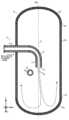
- FIG. 5 is a cross-sectional view of the hot water storage tank 10 cut along a cut plane that includes the outlet 28a and is orthogonal to the vertical direction G. Further, FIG. 6 is a sectional view taken along the line DD in FIG. 5.
- the horizontal portion 27a of the inflow pipe 27 extends in the X-axis direction. Further, as shown in FIG. 6, the vertical portion 27b extends in the vertical direction G.
- the inflow pipe 27 discharges hot water from the inflow port 27c in a direction inclined from the vertical direction G to the +X-axis direction.
- the +X-axis direction is an example of the first direction.
- causes for discharging hot water in a direction inclined in the +X-axis direction include centrifugal force being applied to the hot water when the hot water passes through the curved portion 27d, or vertical portion 27b being inclined from the vertical direction G.
- the high temperature hot water is discharged into the hot water storage tank 10 in a biased state in the +X-axis direction with respect to the axis CC of the inlet 27c.
- the flow rate of high-temperature hot water flowing in the +X-axis direction inside the hot water storage tank 10 is smaller than the flow rate of high-temperature hot water flowing in the -X-axis direction.
- the outflow port 28a is disposed away from the axis CC of the inflow port 27c in the ⁇ X-axis direction on the DD line cross section in order to suppress the direct inflow of hot water discharged from the inflow port 27c.
- the ⁇ X-axis direction is an example of the second direction.
- the high-temperature hot water that flows into the hot water storage tank 10 from the inlet 27c takes a long path before reaching the outlet 28a. This suppresses the occurrence of short cycles.
- the position of the outlet 28a is not limited to the positions shown in FIGS. 5 and 6, and can be selected as appropriate.
- the hot water storage type water heater 100 includes a second outflow pipe 29 that supplies hot water from the hot water storage tank 10 to the second heating heat exchanger 11, and either the outflow pipe 28 or the second outflow pipe 29 Embodiment 4 of the present disclosure, in which hot water is supplied to the second heating heat exchanger 11 via one side, will be described with a focus on the differences from Embodiment 1.
- the tank unit 50 switches the flow path of hot water with a second outflow pipe 29 that supplies hot water from the hot water storage tank 10 to the second heating heat exchanger 11.
- a second flow path switching device 30 an outgoing pipe 31 that connects the second flow path switching device 30 and the second heating heat exchanger 11 , and a temperature sensor that detects the temperature of hot water in the hot water storage tank 10
- the tank unit 50 is different from the tank unit 50 according to the first embodiment in that it includes the following.
- the second outflow pipe 29 is connected to a position below the position where the outflow pipe 28 of the tank body 10A is connected.
- the second outflow pipe 29 does not extend inside the hot water storage tank 10, and the upstream end of the second outflow pipe 29 is joined to the inner wall of the tank body 10A.
- a second outflow port 29a through which hot water flows out from the hot water storage tank 10 is provided at the upstream end of the second outflow pipe 29, which is the end of the second outflow pipe 29 inside the hot water storage tank 10.
- the second outlet 29a opens in the horizontal direction.
- the second outlet 29a is located below the outlet 28a.
- the axis of the second outlet 29a includes the axis of the inlet 27c as well as the axis of the outlet 28a and the tank body 10A, and is included in a plane JJ parallel to the vertical direction G. ing.
- the second outflow port 29a is configured such that the hot water that has come into contact with the lower mirror plate 10B after being discharged from the inlet 27c flows into the second outlet 29a, and that the hot water that has come into contact with the lower mirror plate 10B after being discharged from the inflow port 27c. It is arranged at a position where the flow of unused hot water into the second outlet 29a is suppressed, that is, at a position shifted from the direction in which hot water is discharged from the outlet 27c. Specifically, the distance in the horizontal direction between the inlet 27c and the second outlet 29a is greater than the distance over which the hot water discharged from the inlet 27c spreads in the horizontal direction before reaching the lower mirror plate 10B.
- the second flow path switching device 30 is connected to the outflow pipe 28 and the second outflow pipe 29. Specifically, the second flow path switching device 30 has an inlet 30a connected to the outflow pipe 28, an inlet 30b connected to the second outflow pipe 29, an outlet 30c connected to the outflow pipe 31, It is equipped with The second flow path switching device 30 closes one of the inlets 30a and 30b and opens the other of the inlets 30a and 30b under the control of the control device 15, thereby allowing the flow of hot water flowing out from the hot water storage tank 10. Switch roads.
- the temperature sensor 32 is a temperature sensor such as a thermocouple or a thermistor, and is attached to the hot water storage tank 10 to detect the temperature of hot water in the hot water storage tank 10. Specifically, the temperature sensor 32 is disposed at a reference position located below the outflow port 28a and above the second outflow port 29a, and the temperature sensor 32 is disposed at a reference position located below the outflow port 28a and above the second outflow port 29a. Detects the temperature of The temperature sensor 32 is electrically connected to the control device 70 and transmits an output signal indicating the detection result of the temperature of hot water to the control device 70.
- the control device 70 causes the control device 15 included in the tank unit 50 to control the operation of the second flow path switching device 30.
- the control device 70 switches the flow path of the hot water supplied from the hot water storage tank 10 to the second heating heat exchanger 11 according to the temperature distribution of hot water in the hot water storage tank 10 along the vertical direction.
- city water which is low-temperature hot water
- city water which is low-temperature hot water
- the low temperature hot water that has flowed into the hot water storage tank 10 forms a layer at the bottom of the hot water storage tank 10, and the high temperature hot water forms a layer above this low temperature hot water.
- temperature distribution 1 the temperature distribution in which the boundary surface between the high temperature hot water layer and the low temperature hot water layer is located above the outlet 28a
- temperature distribution 2 the temperature distribution in which the temperature distribution is located below the outlet 28a
- the control device 70 detects the temperature distribution of the hot water in the hot water storage tank 10 based on the temperature of the hot water at the reference position in the hot water storage tank 10 detected by the temperature sensor 32, and controls the flow path of the hot water according to the detected temperature distribution. Control.
- the control device 70 controls the temperature distribution of the hot water in the hot water storage tank 10 to be the temperature distribution. It is determined that it is 1. If the temperature of the hot water in the hot water storage tank 10 at the reference position detected by the temperature sensor 32 is lower than the reference temperature, the control device 70 determines that the temperature distribution of the hot water in the hot water storage tank 10 is temperature distribution 2.
- the reference temperature corresponds to a temperature that serves as a standard for classifying high-temperature hot water and low-temperature hot water, and is set to 40 [° C.] in this embodiment. Note that this is just an example, and the reference temperature can be set arbitrarily.
- control device 70 determines that the temperature distribution of hot water in the hot water storage tank 10 is temperature distribution 1
- the control device 70 controls the second flow path switching device 30 to open the inlet 30a and close the inlet 30b.
- the flow path of hot water is controlled so that hot water flows through the outflow pipe 28 and the outgoing pipe 31, but does not flow through the second outflow pipe 29.
- hot water is supplied to the second heating heat exchanger 11 via the outflow pipe 28 without being supplied to the second heating heat exchanger 11 via the second outflow pipe 29. .
- the control device 70 determines that the temperature distribution of hot water in the hot water storage tank 10 is temperature distribution 2
- the control device 70 controls the second flow path switching device 30 to open the inlet 30b and close the inlet 30a.
- the flow path of hot water is controlled so that hot water flows through the second outflow pipe 29 and the outgoing pipe 31 and hot water does not flow through the outflow pipe 28.
- hot water is not supplied to the second heating heat exchanger 11 via the outflow pipe 28, but hot water is supplied to the second heating heat exchanger 11 via the second outflow pipe 29. .
- the hot water existing near the outlet 28a and the hot water existing near the second outlet 29a are both low-temperature hot water.
- the hot water flow path is controlled so that the hot water in the hot water storage tank 10 flows out from the outflow port 28a without flowing out from the second outflow port 29a. It takes a long path from flowing into the hot water to passing through a layer of low-temperature hot water to reaching the outlet 28a. Therefore, it takes a long time to heat the surrounding low-temperature hot water from when the high-temperature hot water flows into the hot water storage tank 10 until it flows out to the second heating heat exchanger 11. Therefore, boiling efficiency is high.
- Temperature distribution 2 is a temperature distribution in which the interface between the high temperature hot water layer and the low temperature hot water layer is located below the outlet 28a and above the second outlet 29a. , and a temperature distribution in which this boundary surface is located below the second outlet 29a.
- temperature distribution 2A the former temperature distribution
- temperature distribution 2B the latter temperature distribution
- the hot water existing near the outlet 28a is high temperature hot water
- the hot water existing near the second outlet 29a is low temperature hot water. be.
- the hot water flow path is controlled so that the hot water in the hot water storage tank 10 flows out from the second outflow port 29a without flowing out from the outflow port 28a. Outflow to the heating heat exchanger 11 is suppressed. Therefore, boiling efficiency is high.
- the hot water existing near the outlet 28a and the hot water existing near the second outlet 29a are both high-temperature hot water.
- the hot water flow path is controlled so that the hot water in the hot water storage tank 10 does not flow out from the outflow port 28a but flows out from the second outflow port 29a, so that the hot water flows into the hot water storage tank 10 through the inflow port 27c.
- the path taken by hot water until it flows out from the hot water storage tank 10 is short. Therefore, the time for the inflowing hot water to flow inside the layer of high temperature hot water is short. Therefore, boiling efficiency is high.
- the hot water storage type water heater 100 includes the second outflow pipe 29 that supplies hot water from the hot water storage tank 10 to the second heating heat exchanger 11.
- a second outlet 29a is provided at the end of the second outlet pipe 29 inside the hot water storage tank 10.
- the second outlet 29a is located below the outlet 28a.
- Hot water is supplied to the second heating heat exchanger 11 via the outflow pipe 28 without supplying hot water to the second heating heat exchanger 11 via the second outflow pipe 29.
- the hot water storage type water heater 100 When the temperature of hot water in the hot water storage tank 10 at the reference position is lower than the reference temperature, the hot water storage type water heater 100 does not supply hot water to the second heating heat exchanger 11 via the outflow piping 28 . Hot water is supplied to the second heating heat exchanger 11 through the outflow pipe 29 . According to such a configuration, the boiling efficiency is high regardless of the temperature distribution of hot water in the hot water storage tank 10.
- the horizontal distance between the inlet 27c and the outlet 28a is longer than the distance over which the hot water discharged from the inlet 27c spreads in the horizontal direction before reaching the lower mirror plate 10B.
- the outlet 28a is an outlet for hot water that has come into contact with the lower end plate 10B after being discharged from the inlet 27c to flow into the outlet 28a, and an outlet for hot water that has not come into contact with the lower end plate 10B after being discharged from the inlet 27c. It can be placed at any position where the flow into 28a is suppressed.
- the outflow port 28a may be arranged above the inflow port 27c.
- the outflow pipe 28 was described as not extending inside the hot water storage tank 10, but this is only an example, and the outflow pipe 28 is provided in the hot water storage tank 10.
- the hot water storage tank 10 may extend into the hot water storage tank 10 by penetrating the through hole.
- the outflow port 28a of the outflow pipe 28 allows the hot water that comes into contact with the lower mirror plate 10B after being discharged from the inflow port 27c to flow into the outflow port 28a, as in the second embodiment. It is preferable to arrange the hot water at a position where hot water that is not in contact with the lower mirror plate 10B is prevented from flowing into the outlet 28a after being discharged from the lower mirror plate 10B. According to such a configuration, the boiling efficiency is high.
- five temperature sensors are attached to the hot water tank 10, but this is just an example, and the number of temperature sensors may be any number greater than or equal to two.
- the second outflow pipe 29 is explained as not extending inside the hot water storage tank 10, but this is only an example, and the second outflow pipe 29 is not extended inside the hot water storage tank 10.
- the hot water storage tank 10 may extend into the hot water storage tank 10 by passing through a through hole provided in the hot water storage tank 10 .
- the second outflow port 29a of the second outflow pipe 29 is similar to the outflow port 28a according to the second embodiment, in which hot water that has come into contact with the lower mirror plate 10B after being discharged from the inflow port 27c is connected to the second outflow port 29a.
- the hot water it is preferable to arrange the hot water at a position where the hot water that has flowed into the second outflow port 29a and is not in contact with the lower mirror plate 10B after being discharged from the inflow port 27c is suppressed from flowing into the second outflow port 29a.
- the second outlet 29a may be opened upward, similar to the outlet 28a according to the second embodiment. According to such a configuration, the boiling efficiency is high.
- the second outflow pipe 29 is connected to the tank body 10A of the hot water storage tank 10, but this is only an example, and the second outflow pipe 29 is connected to the hot water storage tank 10A. 10 may be connected to the lower end plate 10B.
- the control device 70 detects the temperature distribution of hot water in the hot water storage tank 10 based on the temperature of hot water in the hot water storage tank 10 at the reference position detected by the temperature sensor 32, and determines the temperature distribution of hot water in the hot water storage tank 10 based on the temperature of hot water in the hot water storage tank 10 at the reference position detected by the temperature sensor 32
- the explanation has been made assuming that the flow path of hot water flowing out from the hot water storage tank 10 is switched, this is only an example.
- the control device 70 detects the temperature distribution of the hot water in the hot water storage tank 10 based on the output signals output from the five temperature sensors described in the first embodiment, and switches the flow path of the hot water according to the detection result. It's okay. According to such a configuration, the boiling efficiency is high.
- Embodiments 1 to 4 above can be arbitrarily combined with each other.
- the outlet 28a may be configured to open upward. According to such a configuration, the boiling efficiency is high.
- the inflow pipe 27 discharges hot water from the inlet 27c in a direction inclined from the vertical direction G to the first direction.
- the outlet 28a may be configured to be located away from the axis CC of the inlet 27c in a second direction different from the first direction. According to such a configuration, the boiling efficiency is high.
- the inflow pipe 27 discharges hot water from the inflow port 27c in a direction inclined from the vertical direction G to the first direction, and the second outflow port 28c is connected to the axis CC of the inflow port 27c. It may be configured to be located away from the first direction in a second direction different from the first direction. According to such a configuration, the boiling efficiency is high.
Landscapes
- Engineering & Computer Science (AREA)
- Physics & Mathematics (AREA)
- Thermal Sciences (AREA)
- Chemical & Material Sciences (AREA)
- Combustion & Propulsion (AREA)
- Mechanical Engineering (AREA)
- General Engineering & Computer Science (AREA)
- Heat-Pump Type And Storage Water Heaters (AREA)
Priority Applications (1)
| Application Number | Priority Date | Filing Date | Title |
|---|---|---|---|
| JP2024521937A JPWO2023224027A1 (cg-RX-API-DMAC7.html) | 2022-05-16 | 2023-05-16 |
Applications Claiming Priority (2)
| Application Number | Priority Date | Filing Date | Title |
|---|---|---|---|
| JP2022-080070 | 2022-05-16 | ||
| JP2022080070 | 2022-05-16 |
Publications (1)
| Publication Number | Publication Date |
|---|---|
| WO2023224027A1 true WO2023224027A1 (ja) | 2023-11-23 |
Family
ID=88835547
Family Applications (1)
| Application Number | Title | Priority Date | Filing Date |
|---|---|---|---|
| PCT/JP2023/018232 Ceased WO2023224027A1 (ja) | 2022-05-16 | 2023-05-16 | 貯湯式給湯機 |
Country Status (2)
| Country | Link |
|---|---|
| JP (1) | JPWO2023224027A1 (cg-RX-API-DMAC7.html) |
| WO (1) | WO2023224027A1 (cg-RX-API-DMAC7.html) |
Citations (5)
| Publication number | Priority date | Publication date | Assignee | Title |
|---|---|---|---|---|
| JPH07213882A (ja) * | 1994-02-09 | 1995-08-15 | Univ Sangyo Kk | 薬剤などの混合装置 |
| JP2007057165A (ja) * | 2005-08-25 | 2007-03-08 | Sunrise Kogyo Kk | 貯湯槽 |
| JP2012189277A (ja) * | 2011-03-11 | 2012-10-04 | Shimakura Tekkosho:Kk | 貯湯式給湯装置及びその熱源水供給方法 |
| JP2015209226A (ja) * | 2014-04-25 | 2015-11-24 | ダイキン工業株式会社 | 蓄熱タンクユニットならびに空調システム |
| WO2022071207A1 (ja) * | 2020-09-30 | 2022-04-07 | ダイキン工業株式会社 | 給湯装置 |
Family Cites Families (2)
| Publication number | Priority date | Publication date | Assignee | Title |
|---|---|---|---|---|
| JP3141319U (ja) * | 2008-02-15 | 2008-05-01 | 幸雄 小松 | 攪拌式貯湯装置 |
| WO2020196654A1 (ja) * | 2019-03-27 | 2020-10-01 | ダイキン工業株式会社 | 給湯装置 |
-
2023
- 2023-05-16 WO PCT/JP2023/018232 patent/WO2023224027A1/ja not_active Ceased
- 2023-05-16 JP JP2024521937A patent/JPWO2023224027A1/ja active Pending
Patent Citations (5)
| Publication number | Priority date | Publication date | Assignee | Title |
|---|---|---|---|---|
| JPH07213882A (ja) * | 1994-02-09 | 1995-08-15 | Univ Sangyo Kk | 薬剤などの混合装置 |
| JP2007057165A (ja) * | 2005-08-25 | 2007-03-08 | Sunrise Kogyo Kk | 貯湯槽 |
| JP2012189277A (ja) * | 2011-03-11 | 2012-10-04 | Shimakura Tekkosho:Kk | 貯湯式給湯装置及びその熱源水供給方法 |
| JP2015209226A (ja) * | 2014-04-25 | 2015-11-24 | ダイキン工業株式会社 | 蓄熱タンクユニットならびに空調システム |
| WO2022071207A1 (ja) * | 2020-09-30 | 2022-04-07 | ダイキン工業株式会社 | 給湯装置 |
Also Published As
| Publication number | Publication date |
|---|---|
| JPWO2023224027A1 (cg-RX-API-DMAC7.html) | 2023-11-23 |
Similar Documents
| Publication | Publication Date | Title |
|---|---|---|
| CN204026991U (zh) | 供暖供给热水系统 | |
| CN109595846A (zh) | 热泵机组及控制热泵机组的方法 | |
| CN105240996A (zh) | 空调器的控制方法 | |
| JP5171868B2 (ja) | 貯湯式給湯装置 | |
| CN105783136A (zh) | 一种室外空调机及空调系统 | |
| JP2014109430A (ja) | ヒートポンプ熱源システム | |
| TWI409418B (zh) | 多功能熱泵空調系統 | |
| WO2023224027A1 (ja) | 貯湯式給湯機 | |
| CN207335011U (zh) | 空调系统 | |
| US20080066807A1 (en) | Hot water supply device | |
| JP2011153772A (ja) | 貯湯式給湯装置 | |
| JP7037094B1 (ja) | 給湯装置 | |
| JP2014181870A (ja) | 冷凍サイクル装置 | |
| JP2008241176A (ja) | 冷凍サイクル装置 | |
| JP2010121840A (ja) | 温水暖房装置 | |
| JP2004361046A (ja) | ヒートポンプ式給湯装置 | |
| JP2009264714A (ja) | ヒートポンプ温水システム | |
| JP7607844B1 (ja) | 気液分離装置 | |
| JP4753791B2 (ja) | ヒートポンプ式給湯機 | |
| JP4749228B2 (ja) | ヒートポンプ式給湯機 | |
| JP4595546B2 (ja) | ヒートポンプ装置 | |
| JP7777487B2 (ja) | タンク | |
| CN119713436B (zh) | 空调系统、空调器及空调系统的控制方法 | |
| CN223929956U (zh) | 饮水机 | |
| JP2003262397A (ja) | 給湯装置 |
Legal Events
| Date | Code | Title | Description |
|---|---|---|---|
| 121 | Ep: the epo has been informed by wipo that ep was designated in this application |
Ref document number: 23807629 Country of ref document: EP Kind code of ref document: A1 |
|
| WWE | Wipo information: entry into national phase |
Ref document number: 2024521937 Country of ref document: JP |
|
| NENP | Non-entry into the national phase |
Ref country code: DE |
|
| 122 | Ep: pct application non-entry in european phase |
Ref document number: 23807629 Country of ref document: EP Kind code of ref document: A1 |