WO2023223407A1 - 車両制御装置、経路生成方法、及び非一時的なコンピュータ可読媒体 - Google Patents
車両制御装置、経路生成方法、及び非一時的なコンピュータ可読媒体 Download PDFInfo
- Publication number
- WO2023223407A1 WO2023223407A1 PCT/JP2022/020472 JP2022020472W WO2023223407A1 WO 2023223407 A1 WO2023223407 A1 WO 2023223407A1 JP 2022020472 W JP2022020472 W JP 2022020472W WO 2023223407 A1 WO2023223407 A1 WO 2023223407A1
- Authority
- WO
- WIPO (PCT)
- Prior art keywords
- vehicle
- route
- attitude
- target
- target position
- Prior art date
- Legal status (The legal status is an assumption and is not a legal conclusion. Google has not performed a legal analysis and makes no representation as to the accuracy of the status listed.)
- Ceased
Links
Images


Classifications
-
- G—PHYSICS
- G05—CONTROLLING; REGULATING
- G05D—SYSTEMS FOR CONTROLLING OR REGULATING NON-ELECTRIC VARIABLES
- G05D1/00—Control of position, course, altitude or attitude of land, water, air or space vehicles, e.g. using automatic pilots
- G05D1/02—Control of position or course in two dimensions
Definitions
- the present disclosure relates to a vehicle control device, a route generation method, and a non-transitory computer-readable medium.
- Forklifts that operate autonomously through remote control or the like need to move to a position directly facing the pallet to be lifted in order to lift the pallet when carrying out cargo handling work.
- Non-Patent Document 1 discloses an algorithm for calculating the shortest path between two points. Specifically, the algorithm disclosed in Non-Patent Document 1 calculates the shortest route between two points by combining movement using the minimum turning radius and movement along a straight line.
- Non-Patent Document 1 When the method for calculating the shortest route disclosed in Non-Patent Document 1 is applied to an autonomously operating forklift, the forklift travels the shortest distance to the target position, and after approaching the target position, the forklift is turned back and forth several times. , it may advance to a position directly facing the pallet. Furthermore, in the method for calculating the shortest route disclosed in Non-Patent Document 1, when moving other than moving in a straight line, movement is performed using the minimum turning radius. Therefore, when the forklift is turned back and moved to a position directly facing the pallet, there is a possibility that a path that will collide with the pallet will be calculated.
- one object of the present disclosure is to provide a vehicle control device, a route generation method, and a program that can calculate a route for moving in a target position and in a target posture.
- Our goal is to provide the following.
- the vehicle control device is capable of moving from a first attitude to the target position without changing the curvature and turning direction so that the vehicle assumes the target attitude at the target position.
- a calculation unit that calculates a first straight line indicating a set of one relay point; A first route for the vehicle to move to the relay point, and a route for the vehicle to move from the first relay point to the target position so as to assume the target attitude at the target position without changing the curvature and turning direction.
- a second path for moving, and a path generation unit that generates a path, wherein the first relay point included in the first straight line moves to the target position so as to have the target posture. It is determined according to the turning radius when turning.
- a route control method provides a route control method that allows the vehicle to move from a first attitude to the target position without changing the curvature and turning direction so that the vehicle assumes the target attitude at the target position.
- a first straight line indicating a set of one relay point is calculated, and from the current position to the first relay point so that the first attitude is obtained at the first relay point on the first straight line.
- the vehicle moves to the target position from the first route for the vehicle to move and the first relay point so as to assume the target attitude at the target position without changing the curvature and turning direction. and the first relay point included in the first straight line is determined according to the turning radius when moving to the target position so as to have the target attitude.
- a program according to a third aspect of the present disclosure includes a first program capable of moving from a first posture to the target position without changing the curvature and turning direction so that the vehicle assumes the target posture at the target position.
- a first straight line indicating a set of relay points is calculated, and the first relay points included in the first straight line are set according to a turning radius when moving to the target position so as to have the target attitude.
- a vehicle control device a route generation method, and a program that can calculate a route for moving to a target position and a target posture.
- FIG. 1 is a configuration diagram of a vehicle control device according to a first embodiment. 7 is a flowchart of route generation processing according to the first embodiment.
- FIG. 2 is a configuration diagram of a vehicle control device according to a second embodiment.
- FIG. 7 is a diagram showing intersections calculated by an intersection calculation unit according to the second embodiment.
- FIG. 7 is a diagram illustrating a travel route to a destination according to the second embodiment.
- FIG. 7 is a diagram illustrating a travel route to a destination according to the second embodiment.
- FIG. 7 is a diagram illustrating a travel route to a destination according to the second embodiment.
- FIG. 7 is a diagram illustrating a travel route to a destination according to the second embodiment.
- FIG. 7 is a diagram illustrating a travel route to a destination according to the second embodiment.
- FIG. 7 is a diagram illustrating a travel route to a destination according to the second embodiment.
- 7 is a flowchart of route generation processing according to the second embodiment.
- Vehicle control device 10 may be a computer device that operates by a processor executing a program stored in memory.
- Vehicle control device 10 may be an information processing device, for example, a server device.
- the vehicle control device 10 may be composed of a plurality of computer devices. In this case, the components or functions constituting the vehicle control device 10 may be distributed and arranged in a plurality of computer devices.
- the plurality of computers may be connected via a network or directly via a cable or the like.
- the vehicle control device 10 has a calculation section 11 and a route generation section 12.
- the calculation unit 11 and the route generation unit 12 may be software or modules whose processing is executed by a processor executing a program stored in a memory.
- the calculation unit 11 and the route generation unit 12 may be hardware such as a circuit or a chip.
- the calculation unit 11 calculates a straight line indicating a set of relay points that can move from the first posture to the destination position without changing the curvature and turning direction so that the vehicle assumes the desired posture at the destination position.
- the vehicle may be a vehicle that moves autonomously, a vehicle that moves by remote control, a vehicle that moves by assisting the driver's operation through computer control, or the like.
- the vehicle may also be controlled by a non-holonomic system.
- the vehicle may be a transport vehicle that transports cargo, and may be a forklift, for example. Further, the vehicle may be a mobile robot (steering robot) that turns by turning a steering wheel.
- the target position may be indicated using two-dimensional coordinates or three-dimensional coordinates, for example.
- the target attitude may be expressed using an angle in the front direction of the vehicle with a certain direction as a reference at the target position.
- the front direction of the vehicle may be the direction of travel of the vehicle.
- the first attitude is the attitude at the relay point.
- the attitude at the relay point may be indicated using the angle of the front direction of the vehicle at the relay point with respect to the direction used to indicate the target attitude.
- Moving to the target position without changing the curvature and turning direction means moving to the target position on the circumference determined according to the turning radius, and furthermore, moving to the target position at the target position. good.
- the direction of the target attitude and the direction of the first attitude may be a direction tangent to a circle in which the vehicle moves and a direction in which the vehicle travels.
- the direction of the target attitude is the direction that is tangent to the circle in which the vehicle is moving at the destination position and the direction in which the vehicle is traveling
- the direction of the first attitude is the direction that is tangent to the circle in which the vehicle is moving at the relay point and the direction in which the vehicle is traveling. It may be the direction of travel.
- the relay point is determined according to the turning radius. That is, the position of the relay point changes by changing the turning radius.
- the calculation unit 11 calculates a straight line connecting the positions of a plurality of relay points determined by changing the turning radius.
- a straight line is a straight line on two-dimensional coordinates or three-dimensional coordinates. The straight line uses the same two-dimensional coordinates or three-dimensional coordinates as those used to indicate the target position. That is, the destination position and the relay point are shown as different points on the same coordinates.
- the route generation unit 12 generates a first route for the vehicle to move from the current position to the first relay point on the straight line so that the vehicle assumes the first attitude at the first relay point. Further, the route generation unit 12 generates a second route for the vehicle to move from the first relay point to the target position so that the vehicle assumes the target attitude at the target position without changing the curvature and turning direction.
- the first route may include a straight route and a curved route, or may include only one of the straight and curved routes.
- the calculation unit 11 calculates a straight line indicating a set of relay points that can move from the first attitude to the target position without changing the curvature and turning direction so that the vehicle assumes the target attitude at the target position. (S11).
- the route generation unit 12 generates a first route for the vehicle to move from the current position to the first relay point on the straight line so as to have a first attitude at the first relay point. (S12).
- the route generation unit 12 generates a second route for the vehicle to move from the first relay point to the target position so as to assume the target attitude at the target position without changing the curvature and turning direction; (S13).
- the vehicle control device 10 generates a route from the current position to the target position so that the target posture is at the target position.
- the route from the current position to the destination position includes relay points determined according to the turning radius of the vehicle.
- the vehicle control device 10 can generate different routes depending on the turning radius. As a result, it is possible to reduce the number of times the vehicle has to turn back to move to the target position, so it is possible to avoid the vehicle colliding with an obstacle present at the target position.
- the obstacle may be, for example, a pallet to be transported.
- Vehicle control device 20 may be a computer device that operates by a processor executing a program stored in memory.
- the vehicle control device 20 controls the operation of a forklift, which is a vehicle.
- a forklift which is a vehicle.
- the vehicle control device 20 controls the operation of a forklift; however, the object to be controlled by the vehicle control device 20 is not limited to a forklift.
- the vehicle control device 20 may be mounted on a forklift and control the drive section of the forklift.
- the vehicle control device 20 may remotely control the forklift by communicating via a network with a computer device that controls the drive unit of the forklift.
- Controlling the drive unit may mean, for example, controlling the steering operation of a forklift.
- the steering operation may be to determine the angle of the moving direction of the forklift with respect to the front direction of the forklift. The steering operation is determined depending on, for example, the turning radius of the forklift.
- the vehicle control device 20 generates a route for a forklift that performs cargo handling work, and the forklift moves along the route generated by the vehicle control device 20.
- the position directly facing the pallet is a position where the forks of the forklift can be inserted into the holes of the pallet as the forklift moves forward.
- the position facing the pallet may be a position where a straight line extending in the extending direction of the hole of the pallet into which the fork is inserted matches a straight line extending in the extending direction of the fork of the forklift.
- Moving the forklift to a position directly facing the pallet may be referred to as an alignment process.
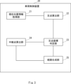
- the vehicle control device 20 includes a current position information acquisition section 21, an intersection calculation section 22, an intersection coordinate determination section 23, a relay point calculation section 24, and a route generation section 25.
- Each component constituting the vehicle control device 20 may be software or a module whose processing is executed by a processor executing a program stored in a memory. Alternatively, each component constituting the vehicle control device 20 may be hardware such as a circuit or a chip.
- the calculation unit 11 in the vehicle control device 10 corresponds to the intersection calculation unit 22 and the relay point calculation unit 24 in the vehicle control device 20. Further, the route generation unit 12 in the vehicle control device 10 corresponds to the route generation unit 25 in the vehicle control device 20.
- the current position information acquisition unit 21 acquires information regarding the current position and current posture of the forklift.
- the current position information acquisition unit 21 may estimate the current position and posture of the forklift using an image taken using a camera installed on the forklift. Estimating may also be interpreted as specifying.
- the camera may be installed at a position where it can photograph the front of the forklift.
- the front of the forklift may be the direction in which the forklift moves forward.
- the camera may also be installed at a position where it can photograph the direction in which the forklift is moving backward.
- the image taken using the camera may be, for example, an RGB (Red Green Blue) image.
- readable identification information is affixed to the pallet placed at the target location of the forklift.
- a QR Quick Response
- QR code registered trademark
- the current location information acquisition unit 21 recognizes the QR (Quick Response) marker pasted on the surface of the pallet from the RGB image.
- the surface of the pallet on which the QR marker is pasted may have a hole into which a fork of a forklift is inserted.
- the current position information acquisition unit 21 estimates the position of the QR marker using two-dimensional coordinates within the RGB image.
- the current position information acquisition unit 21 converts the two-dimensional coordinates in the RGB image into a world coordinate system with the origin at the target position, that is, the QR marker, and estimates the current position of the forklift in the world coordinate system.
- the method of converting the two-dimensional coordinates in the RGB image to the world coordinate system may be any commonly used method, and is not limited to a specific method.
- the current position information acquisition unit 21 estimates the current posture of the forklift with respect to the QR marker based on the position of the QR marker in the RGB image.
- the posture of the forklift may be expressed using a straight line extending perpendicularly from the QR marker attached to the surface of the pallet as a reference, and an angle between the reference straight line and a straight line in the front direction of the forklift.
- the target posture at the target position is a state in which the forklift is facing in a direction directly facing the QR marker. That is, the target posture at the target position is a state in which the angle between the straight line that serves as a reference at the target position of the forklift and the straight line in the front direction of the forklift is 0 degrees.
- the intersection calculation unit 22 calculates a straight line indicating a set of relay points that can move from the current posture to the target position without changing the curvature and turning direction so that the forklift assumes the target posture at the target position. Further, the intersection calculation unit 22 calculates the intersection between the extension line of the direction in which the vehicle is facing at the current position and the straight line indicating the set of relay points.
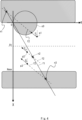
- FIG. 4 shows two-dimensional coordinates (xy coordinates) with the target position of the forklift as the origin.
- the target attitude coincides with the direction in which the x-axis extends.
- the target posture is a state in which the forklift is facing in the negative direction of the x-axis at the origin, which is the target position.
- the shaded area in FIG. 4 indicates an area where forklifts are prohibited from entering. For example, a pallet is placed in the no-trespassing area, and if a forklift truck enters the no-trespassing area, it is assumed that it will collide with the pallet. Further, the circumference of circle C0 in FIG.
- the 4 indicates a movement path when the forklift moves at the minimum turning radius Rmin so as to assume the desired posture at the desired position.
- the minimum turning radius Rmin may be determined as a specification of the forklift.
- the forklift cannot move from within the area surrounded by circle C0 to the target position and assume the target attitude without changing the curvature and turning direction. Therefore, the area surrounded by circle C0 is also considered a no-trespassing area.
- the prohibited area is indicated as follows.
- Xmax is the value of the x-coordinate of the boundary between the prohibited area and the movable area other than the prohibited area.
- p1, p2, and p3 each indicate the current position of the forklift.
- the forklift is oriented in the direction of the arrow in FIG. 4 at points p1, p2, and p3, and the posture of the forklift at its current position is at an angle ⁇ in all cases of p1, p2, and p3.
- a straight line that serves as a reference when indicating the posture of a forklift using an angle is a straight line that is parallel to the x-axis.
- a straight line f1 indicates a set of relay points at which the forklift can move from a posture at an angle ⁇ to a target posture at a target position without changing the curvature or turning direction. Below, calculation of the equation representing the straight line f1 will be explained.
- intersection of the straight line f1 and the extended line f2 is shown as follows.
- the intersection coordinate determining unit 23 determines which of the following areas the position of the intersection is included in.
- Area 1 The intersection is located within the no-trespassing area, and the x-coordinate value of the intersection is greater than the threshold Xt.
- the intersection of area 1 may be at the position indicated by intersection n3 in FIG.
- Area 2 The intersection is located outside the no-trespassing area.
- the intersection of area 2 may be at the position indicated by intersection n2 in FIG.
- Area 3 The intersection is located within the no-trespassing area, and the x-coordinate value of intersection 1 is smaller than the threshold Xt.
- the intersection of area 3 may be at the position indicated by intersection n1 in FIG.
- the threshold value Xt is a value larger than the value of Rmin, and any value may be used.
- the threshold value Xt may be a value such as 2Rmin or 3Rmin, or may be determined as Xmax/2. If the x-coordinate of the intersection is greater than the threshold Xt, there is a sufficient distance from the forklift's current position to the target position, and it is possible to set a route so that the forklift does not collide with the pallet using a general method.
- the threshold value Xt may be set using a general method as a position at which a path can be set in which the forklift does not collide with the pallet.
- a general method may be, for example, the route setting method disclosed in Non-Patent Document 1.
- the route generation unit 25 If the intersection coordinate determination unit 23 determines that the intersection is included in area 1, the route generation unit 25 generates a route to the destination position using a general method.
- the route generation unit 25 when the intersection coordinate determination unit 23 determines that the intersection is included in area 2, the route generation unit 25 generates a route in which the forklift moves straight to the intersection n2 while maintaining its current posture. Specifically, when the intersection n2 exists in front of the forklift, the route generation unit 25 generates a route in which the forklift moves straight to the intersection n2 while maintaining its current posture. Furthermore, when the intersection point n2 exists behind the forklift, the route generation unit 25 generates a route in which the forklift moves backward to the intersection n2 and then goes straight while maintaining its current posture.
- the route generation unit 25 generates a route that moves from the intersection n2 to the target position without changing the curvature and turning direction. In other words, the route generation unit 25 generates a route that allows the vehicle to move to the target position and assume the target attitude at a specific turning radius.
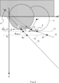
- Circle C0 indicates the circle C0 of the minimum turning radius Rmin in FIG. 4.
- Circle C1 shows the route when moving from p1 with the minimum turning radius Rmin.
- the center C of circle C1 is shown as follows.
- the point A that touches the circle C1 at an angle ⁇ is shown as follows.
- the angle ⁇ is set to a value larger than the angle ⁇ .
- x(1) min indicates the value of the x coordinate of a point on the circle C1 with the minimum turning radius Rmin.
- y(1) min indicates the value of the y coordinate of a point on the circle C1 with the minimum turning radius Rmin.
- FIG. 4 shows an example in which the straight line f3 is parallel to the y-axis, that is, the angle ⁇ is 90 degrees, the angle ⁇ is not limited to 90 degrees.
- Equation 4 of the straight line f4 which represents a set of relay points that can be moved from the attitude of angle ⁇ to the desired attitude at the target position without changing the curvature and turning direction, is shown as follows. .
- the relay point calculation unit 24 calculates the intersection point W ⁇ min between equation 3 of the straight line f3 and equation 4 of the straight line f4.
- the x and y coordinates of the intersection point W ⁇ min are shown as follows.
- a point B that can be moved from the posture of the angle ⁇ to the target posture at the target position without changing the curvature and the turning direction at the minimum turning radius Rmin is shown as follows.
- x(0) min indicates the value of the x coordinate of a point on circle C0 with the minimum turning radius Rmin.
- y(0) min indicates the value of the y coordinate of a point on circle C0 with the minimum turning radius Rmin.
- B(x) indicates the x-coordinate of point B
- W ⁇ min (x) indicates the x-coordinate of intersection W ⁇ min .
- the relay point to which the forklift moves is on the straight line f4, x ⁇ x(0) min , and x ⁇ W ⁇ min (x). In other words, in FIG.
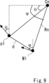
- a straight line f5 connecting the point p1 and a set of positions from the point p1 where the curvature and turning direction are unchanged and the posture is at an angle ⁇ will be explained.
- the position where the attitude of the angle ⁇ is obtained without changing the curvature and the turning direction from the point p1 is determined according to the turning radius. In other words, the position where the attitude of the angle ⁇ is obtained from the point p1 without changing the curvature and the turning direction changes as the turning radius changes.
- Point A in FIG. 7 is a position on circle C1 that is moved from point p1 with a turning radius of Rmin and assumes an attitude of angle ⁇ .
- Point A2 is a position on circle C2 that is moved from point p1 with a turning radius of R2 and assumes an attitude of angle ⁇ .
- C be the center of circle C1, and C2 be the center of circle C2.
- the angle of point C of the triangle connecting point p1, point A, and center C, and the angle of point C of the triangle connecting point p1, point A2, and center C2 are both ⁇ - ⁇ .
- the angle of point p1 in the triangle connecting point p1, point A, and center C, and the triangle connecting point p1, point A2, and center C2 is common.
- the relay point calculation unit 24 calculates the intersection W1 between the straight line f6, which is an extension of the direction in which the forklift in the attitude of the angle ⁇ is facing, and the straight line f5 at the relay point W ⁇ .
- the intersection point W1 between the straight line f6 and the straight line f5, which is an extension of the direction in which the forklift in the attitude of the angle ⁇ is facing at the relay point W ⁇ will be explained using FIG. 8.
- a straight line f6 which is an extension of the direction in which the forklift in the attitude of angle ⁇ at the relay point W ⁇ is facing, is expressed as Equation 6 below.
- W ⁇ (x) indicates the value of the x coordinate at the relay point W ⁇
- W ⁇ (y) indicates the value of the y coordinate at the relay point W ⁇ .
- intersection of straight line f5 and straight line f6 is shown as follows.
- W1(x) indicates the x-coordinate of the intersection W1
- W1(y) indicates the y-coordinate of the intersection W1.
- the turning radius Rn is expressed as the following equation 8 using the distance d.
- the route generation unit 25 calculates the turning radius Rn shown using Equation 8, and then specifies the route 1 that moves from the point p1 to the intersection W1 with the turning radius Rn. Furthermore, the route generation unit 25 specifies a route 2 that moves from the intersection W1 to the relay point W ⁇ while maintaining the attitude of the angle ⁇ . For example, route 2 is specified as a straight route. Further, the route generation unit 25 specifies a route 3 that moves from the relay point W ⁇ to the target position and the target attitude without changing the curvature and turning direction. The route generation unit 25 controls the drive unit of the forklift to move the forklift along the generated route. Alternatively, the route generation unit 25 transmits information regarding the route to a computer device that controls the drive unit of the forklift so that the forklift is moved along the generated route.
- the current position information acquisition unit 21 acquires information regarding the current position and current posture of the forklift (S21).
- the current position may be indicated using two-dimensional coordinates based on the position where the pallet is placed.
- the current posture may be expressed using a straight line in the direction directly facing the pallet as a reference, and an angle between the straight line and a straight line in the front direction of the forklift.
- the intersection calculation unit 22 calculates a straight line indicating a set of relay points that can be moved from the current attitude to the target attitude at the target position without changing the curvature and turning direction (S22). .
- the intersection calculation unit 22 calculates a straight line f1 expressed as Equation 1.
- intersection calculation unit 22 calculates the intersection between the straight line f1 and the extension line of the direction in which the forklift is facing at the current position (S23).
- the extension line f2 shown in equation 2 is used as the extension line in the direction in which the forklift is facing.
- the intersection coordinate determination unit 23 determines whether the intersection is located within the no-entry area (S24). Obstacles such as pallets, shelves, equipment, etc. are placed in the no-entry area, and if a forklift enters the no-entry area, it is assumed that the forklift will collide with the obstruction.
- the route generation unit 25 If the intersection coordinate determination unit 23 determines that the intersection is not located within the no-trespassing area, that is, the intersection is located outside the no-trespassing area, the route generation unit 25 generates a route for when the intersection is included in area 2. Control is performed (S25). Let the intersection included in area 2 be intersection n2. Route control when the intersection is included in area 2 is to generate a route in which the forklift moves straight to intersection n2 while maintaining its current posture, and to generate a route from intersection n2 to the target position without changing the curvature or turning direction. It may also be to generate a route to travel.
- Generating a path from the intersection n2 to the target position without changing the curvature and turning direction means to generate a path that allows movement from the intersection n2 to the target position at a specific turning radius to achieve the desired attitude at the target position. It is to generate.
- step S24 if the intersection coordinate determination unit 23 determines that the intersection is located within the no-trespass area, it determines whether the x-coordinate of the intersection is greater than the threshold Xt (S26). If the intersection coordinate determination unit 23 determines that the x-coordinate of the intersection is greater than the threshold Xt, the route generation unit 25 performs route control when the intersection is included in area 1 (S27). Let the intersection included in area 1 be intersection n3. Route control when the intersection point is included in area 1 may be to generate a route to the destination position using a general method that aims to prevent the forklift from colliding with a pallet or the like.
- the route generation unit 25 performs route control when the intersection is included in area 3 (S28). Let the intersection included in area 3 be intersection n1. Route control when the intersection is included in area 3 may be to generate the routes described using FIGS. 5 to 8.
- the route generation unit 25 can change the route of movement so as to reach the target posture at the target position, depending on the position of the intersection of the straight line f1 and the extension line f2. Moreover, by adjusting the turning radius and moving, the route generation unit 25 can move so as to assume an attitude having an arbitrary angle ⁇ at the intersection point W1 and the relay point W ⁇ . Furthermore, since it is possible to move from the relay point W ⁇ to the target position without changing the curvature and the turning direction, it is possible to avoid a turning operation near the target position. As a result, when the forklift vehicle moves to the target pallet position, it is possible to prevent the forklift vehicle from colliding with the pallet due to the turning operation in the vicinity of the pallet.
- FIG. 11 is a block diagram showing a configuration example of the vehicle control device 10 and the vehicle control device 20 (hereinafter referred to as the vehicle control device 10 etc.) described in the above embodiment.
- the vehicle control device 10 and the like include a network interface 1201, a processor 1202, and a memory 1203.
- Network interface 1201 may be used to communicate with network nodes.
- the network interface 1201 may include, for example, a network interface card (NIC) compliant with the IEEE 802.3 series. IEEE stands for Institute of Electrical and Electronics Engineers.
- NIC network interface card
- the processor 1202 reads software (computer program) from the memory 1203 and executes it, thereby performing the processing of the vehicle control device 10 and the like explained using the flowchart in the above embodiment.
- Processor 1202 may be, for example, a microprocessor, MPU, or CPU.
- Processor 1202 may include multiple processors.
- the memory 1203 is configured by a combination of volatile memory and nonvolatile memory.
- Memory 1203 may include storage located remotely from processor 1202.
- processor 1202 may access memory 1203 via an I/O (Input/Output) interface, which is not shown.
- I/O Input/Output
- memory 1203 is used to store software modules. By reading these software module groups from the memory 1203 and executing them, the processor 1202 can perform the processing of the vehicle control device 10 and the like described in the above embodiments.
- each of the processors included in the vehicle control device 10 etc. in the above-described embodiment has one or more processors including a group of instructions for causing a computer to execute the algorithm explained using the drawings. Run the program.
- the program includes instructions (or software code) that, when loaded into a computer, cause the computer to perform one or more of the functions described in the embodiments.
- the program may be stored on a non-transitory computer readable medium or a tangible storage medium.
- computer readable or tangible storage media may include random-access memory (RAM), read-only memory (ROM), flash memory, solid-state drive (SSD) or other memory technology, CD - Including ROM, digital versatile disc (DVD), Blu-ray disc or other optical disc storage, magnetic cassette, magnetic tape, magnetic disc storage or other magnetic storage device.
- the program may be transmitted on a transitory computer-readable medium or a communication medium.
- transitory computer-readable or communication media includes electrical, optical, acoustic, or other forms of propagating signals.
- the route generating means includes: The vehicle control device according to supplementary note 1, which generates the first route including a route in which the vehicle moves straight to the first relay point while maintaining the first attitude.
- the route generating means includes: The vehicle control device according to supplementary note 2, which generates the first route including a route that moves from the current position to a position where the vehicle assumes the first attitude without changing curvature and turning direction.
- the vehicle control device according to appendix 3 wherein the position from the current position to the first attitude without changing the curvature and the turning direction is determined according to the turning radius.
- the calculation means is A second point indicating a set of second relay points that can move from the second attitude at the current position to the target position without changing the curvature and turning direction so that the vehicle assumes the target attitude at the target position.
- the route generating means includes: The vehicle control device according to any one of Supplementary Notes 1 to 4, which determines route control processing for generating a route to the destination position based on the position of the intersection point. (Appendix 6)
- the route generating means includes: If the intersection point is located outside a no-entry area where entry of the vehicle is prohibited, the vehicle may move straight from the current position to the second relay point while maintaining the second attitude. 3 and a fourth route in which the vehicle moves from the second relay point to the target position so as to assume the target attitude at the target position without changing the curvature and turning direction. , the vehicle control device according to appendix 5.
- the route generating means includes: If the intersection is located inside a no-entry area that prohibits entry of the vehicle, and the distance from the destination position to the intersection is within a threshold, the first route and the second The vehicle control device according to supplementary note 5, which generates a route.
- the route generating means includes: The vehicle control device according to any one of Supplementary Notes 1 to 7, which controls a driving means of the vehicle so that the vehicle moves along the generated route.
- the route generating means includes: 8. The vehicle control device according to any one of Supplementary Notes 1 to 7, wherein information regarding the generated route is transmitted to a computer device that controls a drive means of the vehicle so that the vehicle moves along the generated route.
- the vehicle is The vehicle control device according to any one of Supplementary Notes 1 to 9, which is a forklift that moves to a position directly facing a pallet placed at a target position and transports the pallet.
- (Appendix 11) Calculate a first straight line indicating a set of first relay points that can move from the first attitude to the target position without changing the curvature and turning direction so that the vehicle assumes the target attitude at the target position.
- the first relay point included in the first straight line is A route generation method that is determined according to a turning radius when moving to the target position so as to attain the target attitude. (Appendix 12) Calculate a first straight line indicating a set of first relay points that can move from the first attitude to the target position without changing the curvature and turning direction so that the vehicle assumes the target attitude at the target position.
- the first relay point included in the first straight line is determined according to a turning radius when moving to the target position so as to achieve the target attitude, a first route for the vehicle to move from the current position to the first relay point so as to assume the first attitude at the first relay point on the first straight line; a second route for the vehicle to move from the relay point to the destination position so that the vehicle assumes the target attitude at the target position without changing the curvature and turning direction;
- a non-transitory computer-readable medium that stores a program that causes
- vehicle control device 11 calculation unit 12 route generation unit 20 vehicle control device 21 current position information acquisition unit 22 intersection calculation unit 23 intersection coordinate determination unit 24 relay point calculation unit 25 route generation unit
Landscapes
- Engineering & Computer Science (AREA)
- Aviation & Aerospace Engineering (AREA)
- Radar, Positioning & Navigation (AREA)
- Remote Sensing (AREA)
- Physics & Mathematics (AREA)
- General Physics & Mathematics (AREA)
- Automation & Control Theory (AREA)
- Forklifts And Lifting Vehicles (AREA)
- Control Of Position, Course, Altitude, Or Attitude Of Moving Bodies (AREA)
Priority Applications (2)
| Application Number | Priority Date | Filing Date | Title |
|---|---|---|---|
| JP2024521414A JP7782688B2 (ja) | 2022-05-17 | 2022-05-17 | 車両制御装置、経路生成方法、及びプログラム |
| PCT/JP2022/020472 WO2023223407A1 (ja) | 2022-05-17 | 2022-05-17 | 車両制御装置、経路生成方法、及び非一時的なコンピュータ可読媒体 |
Applications Claiming Priority (1)
| Application Number | Priority Date | Filing Date | Title |
|---|---|---|---|
| PCT/JP2022/020472 WO2023223407A1 (ja) | 2022-05-17 | 2022-05-17 | 車両制御装置、経路生成方法、及び非一時的なコンピュータ可読媒体 |
Publications (1)
| Publication Number | Publication Date |
|---|---|
| WO2023223407A1 true WO2023223407A1 (ja) | 2023-11-23 |
Family
ID=88834819
Family Applications (1)
| Application Number | Title | Priority Date | Filing Date |
|---|---|---|---|
| PCT/JP2022/020472 Ceased WO2023223407A1 (ja) | 2022-05-17 | 2022-05-17 | 車両制御装置、経路生成方法、及び非一時的なコンピュータ可読媒体 |
Country Status (2)
| Country | Link |
|---|---|
| JP (1) | JP7782688B2 (https=) |
| WO (1) | WO2023223407A1 (https=) |
Citations (5)
| Publication number | Priority date | Publication date | Assignee | Title |
|---|---|---|---|---|
| JP2014034230A (ja) * | 2012-08-07 | 2014-02-24 | Nissan Motor Co Ltd | 駐車支援装置及び目標経路生成方法 |
| JP2015055906A (ja) * | 2013-09-10 | 2015-03-23 | 株式会社日立産機システム | 移動体の走行制御手段に対して制御指令を出力する位置検出装置及び移動体システム |
| US20170297621A1 (en) * | 2016-04-13 | 2017-10-19 | Cnh Industrial America Llc | System and method for controlling a vehicle |
| JP2020026165A (ja) * | 2018-08-09 | 2020-02-20 | 住友電気工業株式会社 | 車載装置、駐車制御方法、及びコンピュータプログラム |
| JP2021187248A (ja) * | 2020-05-28 | 2021-12-13 | フォルシアクラリオン・エレクトロニクス株式会社 | 駐車支援装置、及び駐車支援装置の制御方法 |
-
2022
- 2022-05-17 WO PCT/JP2022/020472 patent/WO2023223407A1/ja not_active Ceased
- 2022-05-17 JP JP2024521414A patent/JP7782688B2/ja active Active
Patent Citations (5)
| Publication number | Priority date | Publication date | Assignee | Title |
|---|---|---|---|---|
| JP2014034230A (ja) * | 2012-08-07 | 2014-02-24 | Nissan Motor Co Ltd | 駐車支援装置及び目標経路生成方法 |
| JP2015055906A (ja) * | 2013-09-10 | 2015-03-23 | 株式会社日立産機システム | 移動体の走行制御手段に対して制御指令を出力する位置検出装置及び移動体システム |
| US20170297621A1 (en) * | 2016-04-13 | 2017-10-19 | Cnh Industrial America Llc | System and method for controlling a vehicle |
| JP2020026165A (ja) * | 2018-08-09 | 2020-02-20 | 住友電気工業株式会社 | 車載装置、駐車制御方法、及びコンピュータプログラム |
| JP2021187248A (ja) * | 2020-05-28 | 2021-12-13 | フォルシアクラリオン・エレクトロニクス株式会社 | 駐車支援装置、及び駐車支援装置の制御方法 |
Also Published As
| Publication number | Publication date |
|---|---|
| JP7782688B2 (ja) | 2025-12-09 |
| JPWO2023223407A1 (https=) | 2023-11-23 |
Similar Documents
| Publication | Publication Date | Title |
|---|---|---|
| JP7168211B2 (ja) | 障害物の回避動作を行う移動体およびそのコンピュータプログラム | |
| CN114407929B (zh) | 无人驾驶绕障处理方法、装置、电子设备及存储介质 | |
| KR101503418B1 (ko) | 반자동 주차 기계 | |
| US9254870B2 (en) | Method of generating optimum parking path of unmanned driving vehicle, and unmanned driving vehicle adopting the method | |
| US8521415B2 (en) | Traveling vehicle and method of controlling the same | |
| US12157658B2 (en) | Control device, mobile body, movement control system, control method, and program | |
| JP2020057307A (ja) | 自己位置推定のための地図データを加工する装置および方法、ならびに移動体およびその制御システム | |
| CN111052026A (zh) | 移动体和移动体系统 | |
| WO2019044500A1 (ja) | 位置推定システム、および当該位置推定システムを備える移動体 | |
| CN111033425A (zh) | 移动体、位置推断装置以及计算机程序 | |
| CN110998472A (zh) | 移动体以及计算机程序 | |
| CN111033426A (zh) | 移动体、位置推断装置以及计算机程序 | |
| CN111880525B (zh) | 机器人避障方法、装置、电子设备及可读存储介质 | |
| KR102507973B1 (ko) | 무인 반송 차량 및 이의 동작 방법 | |
| CN111065981A (zh) | 移动体和移动体系统 | |
| US12534347B2 (en) | Vehicle control apparatus, control method, and non-transitory computer readable medium | |
| JP2019175137A (ja) | 移動体および移動体システム | |
| JP6674572B1 (ja) | Slam誘導方式の無人作業車および無人作業システム | |
| JP2019148871A (ja) | 移動体および移動体システム | |
| WO2019194079A1 (ja) | 位置推定システム、当該位置推定システムを備える移動体、およびコンピュータプログラム | |
| JP2011141663A (ja) | 無人搬送車、および、その走行制御方法 | |
| CN115951688A (zh) | 货物装卸方法、系统、电子设备及存储介质 | |
| JP7396353B2 (ja) | 地図作成システム、信号処理回路、移動体および地図作成方法 | |
| KR20230044391A (ko) | 무인 반송 차량 및 이를 포함하는 화물 관리 시스템 | |
| WO2023223407A1 (ja) | 車両制御装置、経路生成方法、及び非一時的なコンピュータ可読媒体 |
Legal Events
| Date | Code | Title | Description |
|---|---|---|---|
| 121 | Ep: the epo has been informed by wipo that ep was designated in this application |
Ref document number: 22942612 Country of ref document: EP Kind code of ref document: A1 |
|
| WWE | Wipo information: entry into national phase |
Ref document number: 2024521414 Country of ref document: JP |
|
| NENP | Non-entry into the national phase |
Ref country code: DE |
|
| 122 | Ep: pct application non-entry in european phase |
Ref document number: 22942612 Country of ref document: EP Kind code of ref document: A1 |