WO2023223064A1 - 全固体電池 - Google Patents
全固体電池 Download PDFInfo
- Publication number
- WO2023223064A1 WO2023223064A1 PCT/IB2022/000285 IB2022000285W WO2023223064A1 WO 2023223064 A1 WO2023223064 A1 WO 2023223064A1 IB 2022000285 W IB2022000285 W IB 2022000285W WO 2023223064 A1 WO2023223064 A1 WO 2023223064A1
- Authority
- WO
- WIPO (PCT)
- Prior art keywords
- positive electrode
- active material
- electrode active
- material layer
- binder
- Prior art date
- Legal status (The legal status is an assumption and is not a legal conclusion. Google has not performed a legal analysis and makes no representation as to the accuracy of the status listed.)
- Ceased
Links
Images


Classifications
-
- H—ELECTRICITY
- H01—ELECTRIC ELEMENTS
- H01M—PROCESSES OR MEANS, e.g. BATTERIES, FOR THE DIRECT CONVERSION OF CHEMICAL ENERGY INTO ELECTRICAL ENERGY
- H01M4/00—Electrodes
- H01M4/02—Electrodes composed of, or comprising, active material
- H01M4/62—Selection of inactive substances as ingredients for active masses, e.g. binders, fillers
- H01M4/621—Binders
- H01M4/622—Binders being polymers
- H01M4/623—Binders being polymers fluorinated polymers
-
- H—ELECTRICITY
- H01—ELECTRIC ELEMENTS
- H01M—PROCESSES OR MEANS, e.g. BATTERIES, FOR THE DIRECT CONVERSION OF CHEMICAL ENERGY INTO ELECTRICAL ENERGY
- H01M10/00—Secondary cells; Manufacture thereof
- H01M10/05—Accumulators with non-aqueous electrolyte
- H01M10/052—Li-accumulators
- H01M10/0525—Rocking-chair batteries, i.e. batteries with lithium insertion or intercalation in both electrodes; Lithium-ion batteries
-
- H—ELECTRICITY
- H01—ELECTRIC ELEMENTS
- H01M—PROCESSES OR MEANS, e.g. BATTERIES, FOR THE DIRECT CONVERSION OF CHEMICAL ENERGY INTO ELECTRICAL ENERGY
- H01M10/00—Secondary cells; Manufacture thereof
- H01M10/05—Accumulators with non-aqueous electrolyte
- H01M10/056—Accumulators with non-aqueous electrolyte characterised by the materials used as electrolytes, e.g. mixed inorganic/organic electrolytes
- H01M10/0561—Accumulators with non-aqueous electrolyte characterised by the materials used as electrolytes, e.g. mixed inorganic/organic electrolytes the electrolyte being constituted of inorganic materials only
- H01M10/0562—Solid materials
-
- H—ELECTRICITY
- H01—ELECTRIC ELEMENTS
- H01M—PROCESSES OR MEANS, e.g. BATTERIES, FOR THE DIRECT CONVERSION OF CHEMICAL ENERGY INTO ELECTRICAL ENERGY
- H01M4/00—Electrodes
- H01M4/02—Electrodes composed of, or comprising, active material
- H01M4/04—Processes of manufacture in general
- H01M4/0402—Methods of deposition of the material
- H01M4/0416—Methods of deposition of the material involving impregnation with a solution, dispersion, paste or dry powder
-
- H—ELECTRICITY
- H01—ELECTRIC ELEMENTS
- H01M—PROCESSES OR MEANS, e.g. BATTERIES, FOR THE DIRECT CONVERSION OF CHEMICAL ENERGY INTO ELECTRICAL ENERGY
- H01M4/00—Electrodes
- H01M4/02—Electrodes composed of, or comprising, active material
- H01M4/04—Processes of manufacture in general
- H01M4/043—Processes of manufacture in general involving compressing or compaction
- H01M4/0435—Rolling or calendering
-
- H—ELECTRICITY
- H01—ELECTRIC ELEMENTS
- H01M—PROCESSES OR MEANS, e.g. BATTERIES, FOR THE DIRECT CONVERSION OF CHEMICAL ENERGY INTO ELECTRICAL ENERGY
- H01M4/00—Electrodes
- H01M4/02—Electrodes composed of, or comprising, active material
- H01M4/36—Selection of substances as active materials, active masses, active liquids
- H01M4/38—Selection of substances as active materials, active masses, active liquids of elements or alloys
- H01M4/40—Alloys based on alkali metals
- H01M4/405—Alloys based on lithium
-
- H—ELECTRICITY
- H01—ELECTRIC ELEMENTS
- H01M—PROCESSES OR MEANS, e.g. BATTERIES, FOR THE DIRECT CONVERSION OF CHEMICAL ENERGY INTO ELECTRICAL ENERGY
- H01M4/00—Electrodes
- H01M4/02—Electrodes composed of, or comprising, active material
- H01M4/62—Selection of inactive substances as ingredients for active masses, e.g. binders, fillers
- H01M4/621—Binders
- H01M4/622—Binders being polymers
-
- H—ELECTRICITY
- H01—ELECTRIC ELEMENTS
- H01M—PROCESSES OR MEANS, e.g. BATTERIES, FOR THE DIRECT CONVERSION OF CHEMICAL ENERGY INTO ELECTRICAL ENERGY
- H01M4/00—Electrodes
- H01M4/02—Electrodes composed of, or comprising, active material
- H01M2004/026—Electrodes composed of, or comprising, active material characterised by the polarity
- H01M2004/027—Negative electrodes
-
- H—ELECTRICITY
- H01—ELECTRIC ELEMENTS
- H01M—PROCESSES OR MEANS, e.g. BATTERIES, FOR THE DIRECT CONVERSION OF CHEMICAL ENERGY INTO ELECTRICAL ENERGY
- H01M4/00—Electrodes
- H01M4/02—Electrodes composed of, or comprising, active material
- H01M2004/026—Electrodes composed of, or comprising, active material characterised by the polarity
- H01M2004/028—Positive electrodes
-
- H—ELECTRICITY
- H01—ELECTRIC ELEMENTS
- H01M—PROCESSES OR MEANS, e.g. BATTERIES, FOR THE DIRECT CONVERSION OF CHEMICAL ENERGY INTO ELECTRICAL ENERGY
- H01M2300/00—Electrolytes
- H01M2300/0017—Non-aqueous electrolytes
- H01M2300/0065—Solid electrolytes
- H01M2300/0068—Solid electrolytes inorganic
-
- Y—GENERAL TAGGING OF NEW TECHNOLOGICAL DEVELOPMENTS; GENERAL TAGGING OF CROSS-SECTIONAL TECHNOLOGIES SPANNING OVER SEVERAL SECTIONS OF THE IPC; TECHNICAL SUBJECTS COVERED BY FORMER USPC CROSS-REFERENCE ART COLLECTIONS [XRACs] AND DIGESTS
- Y02—TECHNOLOGIES OR APPLICATIONS FOR MITIGATION OR ADAPTATION AGAINST CLIMATE CHANGE
- Y02E—REDUCTION OF GREENHOUSE GAS [GHG] EMISSIONS, RELATED TO ENERGY GENERATION, TRANSMISSION OR DISTRIBUTION
- Y02E60/00—Enabling technologies; Technologies with a potential or indirect contribution to GHG emissions mitigation
- Y02E60/10—Energy storage using batteries
-
- Y—GENERAL TAGGING OF NEW TECHNOLOGICAL DEVELOPMENTS; GENERAL TAGGING OF CROSS-SECTIONAL TECHNOLOGIES SPANNING OVER SEVERAL SECTIONS OF THE IPC; TECHNICAL SUBJECTS COVERED BY FORMER USPC CROSS-REFERENCE ART COLLECTIONS [XRACs] AND DIGESTS
- Y02—TECHNOLOGIES OR APPLICATIONS FOR MITIGATION OR ADAPTATION AGAINST CLIMATE CHANGE
- Y02P—CLIMATE CHANGE MITIGATION TECHNOLOGIES IN THE PRODUCTION OR PROCESSING OF GOODS
- Y02P70/00—Climate change mitigation technologies in the production process for final industrial or consumer products
- Y02P70/50—Manufacturing or production processes characterised by the final manufactured product
Definitions
- the present invention relates to an all-solid-state battery.
- lithium secondary batteries that are currently in widespread use use a flammable organic electrolyte as the electrolyte.
- Such liquid-based lithium secondary batteries require more stringent safety measures against leakage, short circuits, overcharging, etc. than other batteries.
- a solid electrolyte is a material mainly composed of an ion conductor capable of ion conduction in a solid state. Therefore, in principle, all-solid-state secondary batteries do not suffer from various problems caused by flammable organic electrolytes, unlike conventional liquid-based lithium secondary batteries. Furthermore, in general, the use of a high potential/large capacity positive electrode material and a large capacity negative electrode material can significantly improve the output density and energy density of the battery.
- JP2019-021459A discloses a method of stably manufacturing a positive electrode active material layer by including a binder in the positive electrode active material layer.
- the present invention provides a means for improving the strength of the positive electrode active material layer while minimizing the reduction in energy density and energy output in an all-solid-state battery equipped with a positive electrode active material layer containing a binder.
- the purpose is to
- the present inventors conducted extensive studies to solve the above problems. As a result, the inventors have found that the above-mentioned problems can be solved by setting the orientation ratio of the binder contained in the positive electrode active material layer to a certain level or more, and have completed the present invention.
- An all-solid-state battery includes a positive electrode including a positive active material layer containing a positive active material and a binder, a negative electrode, and a solid state interposed between the positive electrode and the negative electrode and including a solid electrolyte. It has a power generation element including an electrolyte layer.
- the all-solid-state battery is characterized in that the binder included in the positive electrode active material layer has an orientation rate of 60% or more in a direction perpendicular to the stacking direction of the power generation elements.
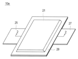
- FIG. 1 is a perspective view showing the appearance of a stacked battery according to an embodiment of the present invention.
- FIG. 2 is a sectional view taken along line 2-2 shown in FIG.
- FIG. 3 is a schematic diagram showing an enlarged cross section of a single cell layer constituting the power generation element of the stacked battery shown in FIGS. 1 and 2.
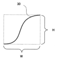
- FIG. 4 is a diagram for explaining a method of calculating the aspect ratio of the binder.
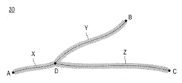
- FIG. 5 is a schematic diagram showing an example of a branched fibrous binder.
- FIG. 6 is a diagram schematically showing an example of a molding process in an embodiment of a manufacturing method for manufacturing a positive electrode active material layer.
- One form of the present invention is a power generation device that includes a positive electrode including a positive electrode active material layer containing a positive electrode active material and a binder, a negative electrode, and a solid electrolyte layer interposed between the positive electrode and the negative electrode and containing a solid electrolyte.
- the all-solid-state battery has an orientation ratio of 60% or more in the direction perpendicular to the lamination direction of the power-generating elements of the binder contained in the positive electrode active material layer. According to the present invention, in an all-solid-state battery equipped with a positive electrode active material layer containing a binder, it is possible to improve the strength of the positive electrode active material layer while minimizing a decrease in energy density and energy output. .
- the solid electrolyte constituting the all-solid-state secondary battery is a material mainly composed of an ion conductor capable of ion conduction in a solid state. Therefore, all-solid-state secondary batteries have the advantage that, unlike conventional liquid-based lithium secondary batteries, various problems caused by flammable organic electrolytes do not occur in principle. Additionally, in general, the use of high-potential, large-capacity positive electrode materials and large-capacity negative electrode materials has the advantage that the output density and energy density of the battery can be significantly improved.
- FIG. 1 is a perspective view showing the appearance of a stacked battery according to an embodiment of the present invention.
- FIG. 2 is a sectional view taken along line 2-2 shown in FIG.
- the stacked battery 10a has a flat rectangular shape, and a positive current collector plate 27 and a negative current collector plate 25 for extracting power are pulled out from both sides of the battery 10a.
- the power generation element 21 is surrounded by the battery exterior material (laminate film 29) of the stacked battery 10a, and the periphery thereof is heat-sealed, and the power generation element 21 has the positive electrode current collector plate 27 and the negative electrode current collector plate 25 connected to the outside. It is sealed when pulled out.
- the positive electrode current collector plate 27 and the negative electrode current collector plate 25 may be drawn out from the same side, or the positive electrode current collector plate 27 and the negative electrode current collector plate 25 may be divided into a plurality of parts and taken out from each side.
- the present invention is not limited to what is shown in FIG.
- the stacked battery 10a of the present embodiment has a structure in which a flat, substantially rectangular power generation element 21 in which charge and discharge reactions actually proceed is sealed inside a laminate film 29 that is a battery exterior material.
- the power generation element 21 has a structure in which a positive electrode, a solid electrolyte layer 17, and a negative electrode are laminated.
- the positive electrode has a structure in which positive electrode active material layers 15 containing a positive electrode active material are disposed on both sides of a positive electrode current collector 11''.
- the negative electrode has a structure in which positive electrode active material layers 15 containing a positive electrode active material are arranged on both sides of a negative electrode current collector 11'.
- active material layers 13 It has a structure in which active material layers 13 are arranged.Specifically, one positive electrode active material layer 15 and an adjacent negative electrode active material layer 13 face each other with a solid electrolyte layer 17 in between, A positive electrode, a solid electrolyte layer, and a negative electrode are stacked in this order.Thereby, the adjacent positive electrode, solid electrolyte layer, and negative electrode constitute one single cell layer 19.Therefore, the stacked battery 10a shown in FIG. , it can be said that it has a configuration in which a plurality of cell layers 19 are stacked and electrically connected in parallel.
- a positive electrode current collector plate (tab) 27 and a negative electrode current collector plate (tab) 25 that are electrically connected to each electrode (positive electrode and negative electrode) are attached to the positive electrode current collector 11'' and the negative electrode current collector 11', respectively, and the battery It has a structure in which it is sandwiched between the ends of the laminate film 29, which is an exterior material, and led out to the outside of the laminate film 29.
- the positive electrode current collector plate 27 and the negative electrode current collector plate 25 are each provided with It may be attached to the positive electrode current collector 11'' and negative electrode current collector 11' of each electrode via a positive electrode lead and a negative electrode lead (not shown) by ultrasonic welding, resistance welding, or the like.
- FIG. 3 is a schematic diagram showing an enlarged cross section of the unit cell layer 19 constituting the power generation element 21 of the stacked battery 10a shown in FIGS. 1 and 2.
- the unit cell layer 19 includes a negative electrode current collector 11', a negative electrode active material layer 13, a solid electrolyte layer 17, and a positive electrode active material layer that constitute the unit cell layer 19. 15 and a positive electrode current collector 11'' are laminated in this order.
- the positive electrode active material layer 15 contains a binder 30, and the binder is The orientation ratio in the vertical direction (the direction of the arrow in the figure) is 60% or more.The details of the "orientation ratio of the binder" will be described later.
- the current collector has a function of mediating the movement of electrons from the electrode active material layer. There is no particular restriction on the material constituting the current collector. As the constituent material of the current collector, for example, metal or conductive resin may be used.
- metals include aluminum, nickel, iron, stainless steel, titanium, copper, and the like.
- a cladding material of nickel and aluminum, a cladding material of copper and aluminum, etc. may be used.
- it may be a foil whose metal surface is coated with aluminum.
- aluminum, stainless steel, copper, and nickel are preferred from the viewpoints of electron conductivity, battery operating potential, adhesion of the negative electrode active material to the current collector by sputtering, and the like.
- examples of resins having conductivity include conductive polymer materials as well as resins in which conductive fillers are added to non-conductive polymer materials.
- the conductive filler can be used without any particular limitation as long as it is a conductive substance.
- metals, conductive carbon, and the like are examples of materials having excellent conductivity, potential resistance, or lithium ion blocking properties.
- the current collector may have a single-layer structure made of a single material, or may have a laminated structure in which layers made of these materials are appropriately combined. From the viewpoint of reducing the weight of the current collector, it is preferable to include at least a conductive resin layer made of a resin having conductivity. Further, from the viewpoint of blocking the movement of lithium ions between the cell layers, a metal layer may be provided on a part of the current collector.
- the positive electrode active material layer includes a positive electrode active material and a binder.
- the type of positive electrode active material is not particularly limited, but may include layered rock salt type active materials such as LiCoO 2 , LiMnO 2 , LiNiO 2 , LiVO 2 , Li(Ni-Mn-Co)O 2 , LiMn 2 O 4 , LiNi 0
- Examples include spinel-type active materials such as .5 Mn 1.5 O 4 , olivine-type active materials such as LiFePO 4 and LiMnPO 4 , and Si-containing active materials such as Li 2 FeSiO 4 and Li 2 MnSiO 4 .
- oxide active materials other than those mentioned above include Li 4 Ti 5 O 12 .
- NMC composite oxide has a layered crystal structure in which lithium atomic layers and transition metal (Mn, Ni, and Co are arranged in an orderly manner) atomic layers are stacked alternately through oxygen atomic layers, and each atom of transition metal M It contains one Li atom, and the amount of Li that can be taken out is twice that of spinel-based lithium manganese oxide, that is, the supply capacity is doubled, and it can have a high capacity.
- the NMC composite oxide also includes a composite oxide in which a part of the transition metal element is replaced with another metal element.
- Other elements in that case include Ti, Zr, Nb, W, P, Al, Mg, V, Ca, Sr, Cr, Fe, B, Ga, In, Si, Mo, Y, Sn, V, Cu. , Ag, Zn, etc., preferably Ti, Zr, Nb, W, P, Al, Mg, V, Ca, Sr, Cr, more preferably Ti, Zr, P, Al, Mg, Cr, and from the viewpoint of improving cycle characteristics, Ti, Zr, Al, Mg, and Cr are more preferred.
- a sulfur-based positive electrode active material is used.
- the sulfur-based positive electrode active material include particles or thin films of organic sulfur compounds or inorganic sulfur compounds, which can release lithium ions during charging and store lithium ions during discharge by utilizing the redox reaction of sulfur. Any substance that can be used is fine.
- positive electrode active materials may be used together. Note that, of course, positive electrode active materials other than those mentioned above may be used.
- the content of the positive electrode active material in the positive electrode active material layer is not particularly limited, but for example, it is preferably within the range of 35 to 99% by mass, and preferably within the range of 40 to 90% by mass. More preferred.
- the positive electrode active material layer according to this embodiment contains a binder, and the orientation rate of the binder in a direction perpendicular to the stacking direction of the power generation elements (also simply referred to as "plane direction") is 60% or more. According to the all-solid-state battery according to this embodiment, since the orientation rate of the binder in the positive electrode active material layer is 60% or more in the plane direction, the positive electrode active material The strength of the layer can be improved.
- the positive electrode active material layer is less likely to crack or collapse due to external force, and it is thought that a decrease in the output of the all-solid-state battery can be prevented.
- the positive electrode active material layer As a method of increasing the strength of the positive electrode active material layer, increasing the binder content contained in the positive electrode active material layer may be considered, but in that case, the energy density of the all-solid-state battery decreases.
- the positive electrode active material layer according to this embodiment by arranging the binder so as to be oriented in the plane direction, sufficient strength can be maintained by the above-mentioned mechanism, so that the content of the binder can be reduced. . It is thought that this makes it possible to obtain an all-solid-state battery that maintains sufficient strength and has a high energy density even if the content of the binder is at least low.
- the orientation rate of the binder in the positive electrode active material layer can be calculated as follows.
- the state of the arrangement of the binder in the cross section of the positive electrode active material layer parallel to the stacking direction of the power generation element is specified.
- the arrangement state of the binder can be identified by observing the cross section using SEM-EDX and mapping elements specific to the binder. Note that, as long as results equivalent to those of SEM-EDX can be obtained, mapping of the binder in the cross section may be performed using AES (Auger electron spectroscopy), EPMA (electron probe microanalysis), or the like.
- the average value of the aspect ratios of the binders is calculated from the arrangement of each binder in the cross section of the positive electrode active material layer.
- the average value of the aspect ratio of the binder is calculated as follows. First, 100 or more binders are extracted from all the binders included in the cross-sectional observation image.
- the aspect ratio is calculated for each extracted binder. Specifically, in the above observation image, as shown in FIG. A rectangle (the rectangle indicated by the broken line in FIG. 4) having the inside W) is set so that the binder 30 is inscribed therein. Then, a value obtained by dividing the length of the horizontal side of the rectangle by the length of the vertical side is calculated as the aspect ratio (1/tan ⁇ ). Then, the average value of the aspect ratios of each extracted binder is calculated and set as the average value (1/tan ⁇ ) of the aspect ratios of the binders.
- ⁇ [°] is calculated from the calculated average value of the aspect ratio (1/tan ⁇ ). Subsequently, from this value of ⁇ , a value calculated based on the following equation 1 is taken as the orientation ratio (%) of the binder in the positive electrode active material layer.
- the orientation rate calculated by observing the cross section of at least one positive electrode active material layer is taken as the orientation rate of the binder in the entire positive electrode active material layer. Can be done.
- the lower limit of the orientation ratio of the binder in the positive electrode active material layer according to this embodiment is 60% or more, preferably 65% or more, more preferably 70% or more, and preferably 75% or more. More preferably, it is 80% or more, particularly preferably 85% or more, and most preferably 85% or more.
- the orientation ratio value of the binder is 90% or less.
- the positive electrode active material layer exerts sufficient internal force when an external force (e.g., tensile stress or shear stress) is applied from a direction perpendicular to the lamination direction.
- an external force e.g., tensile stress or shear stress
- the orientation ratio of the binder according to the present embodiment is preferably 60% or more and 90% or less, more preferably 65% or more and 90% or less, and even more preferably 70% or more and 90% or less. It is even more preferably 75% or more and 90% or less, particularly preferably 80% or more and 90% or less, and most preferably 85% or more and 90% or less.
- the upper limit of the binder content in the positive electrode active material layer according to this embodiment is preferably 3.2% by mass or less, and preferably 3.1% by mass or less, based on the total mass of the positive electrode active material layer. is more preferable, and even more preferably 3.0% by mass or less. When the content of the binder is within this range, the energy density and energy output of the all-solid-state battery will be sufficiently high.
- the lower limit of the binder content in the positive electrode active material layer according to this embodiment is preferably 0.6% by mass or more, more preferably 0.7% by mass or more, and 0.8% by mass. It is more preferably at least 1.0% by mass, particularly preferably at least 1.5% by mass, and most preferably at least 1.5% by mass.
- the content of the binder in the positive electrode active material layer according to this embodiment is preferably 0.6% by mass or more and 3.2% by mass or less, and 0.7% by mass with respect to the total mass of the positive electrode active material layer. % or more and 3.1% by mass or less, further preferably 0.8% by mass or more and 3.0% by mass or less, and 1.0% by mass or more and 3.0% by mass or less. It is particularly preferable, and most preferably 1.5% by mass or more and 3.0% by mass or less.
- the binder is not particularly limited, but examples include the following materials.
- PVDF polyvinylidene fluoride
- polyethylene polypropylene, polymethylpentene, polybutene, polyethernitrile, polytetrafluoroethylene
- Polyacrylonitrile polyimide, polyamide, ethylene-vinyl acetate copolymer, polyvinyl chloride, styrene-butadiene rubber (SBR), ethylene-propylene-diene copolymer, styrene-butadiene-styrene block copolymer and hydrogenated products thereof
- thermoplastic polymers such as styrene/isoprene/styrene block copolymers and their hydrogenated products, tetrafluoroethylene/hexafluoropropylene copolymers (FEP), tetrafluoroethylene/perfluoroalkyl
- the binder preferably contains a fibrous binder from the viewpoint that the strength of the positive electrode active material layer can be made more sufficient by intertwining with other components.
- a "fibrous binder” is one that has an aspect ratio of 10 or more and a minimum ferromagnetic flux in an observed image of a cross section of a positive electrode active material layer using a scanning electron microscope (SEM). It refers to a binder mainly composed of fibers with a diameter of 0.2 ⁇ m or less.
- the aspect ratio is calculated by dividing the maximum Feret diameter of the binder by the minimum Feret diameter.
- the maximum Feret diameter is the maximum distance between two parallel straight lines when the outline of the binder is sandwiched between the two parallel straight lines
- the minimum Feret diameter is the maximum distance between two parallel straight lines when the outline of the binder is sandwiched between the two parallel straight lines. is the minimum distance between the straight lines when The expression that a certain binder is "mainly composed of" the above-mentioned fibers means that the area ratio of the above-mentioned fiber portions to the total area of the binder in the SEM observation image is 50% or more.
- One fibrous binder has a part other than fibers that has an aspect ratio of 10 or more and a minimum Feret diameter of 0.2 ⁇ m or less (a part that has an aspect ratio of less than 10 or a minimum Feret diameter of more than 0.2 ⁇ m). part).
- the area ratio of parts other than fibers to the total area of the fibrous binder in the SEM observation image must be less than 50%, preferably 20% or less, and 10% or less. is more preferable, and even more preferably 5% or less (the lower limit is 0%).
- the fibrous binder includes not only one composed of only one fiber but also one composed of two or more fibers connected to each other.
- FIG. 5 is a schematic diagram showing an example of a branched fibrous binder.
- the binder 30 shown in FIG. 5 has a structure in which fibers X, fibers Y, and fibers Z are connected to each other.
- Each broken line represents a line connecting the fiber width centers (1/2 width), and points A, B, and C represent the ends of each broken line. Note that the end of each broken line coincides with the end of the fiber.
- Point D represents the intersection of three broken lines. That is, in the binder 30 shown in FIG. 5, fibers X from point A to point D, fibers Y from point B to point D, and fibers Z from point C to point D are combined at point D. It can also be said that it has a shape.
- the maximum Feret diameter of the fibers X in the binder 30 shown in FIG. 5 is defined as the distance from point A to point D.
- the maximum Feret diameter of fiber Y is the distance from point B to point D
- the maximum Feret diameter of fiber Z is the distance from point C to point D.
- the minimum Feret diameter of the fiber X is the minimum distance between two parallel straight lines when the outline of the binder (fiber) from point A to point D is sandwiched between the two parallel straight lines.
- the minimum Feret diameters of fibers Y and Z In the binder 30 shown in FIG. 5, the fibers Y and Z have an aspect ratio of 10 or more and a minimum Feret diameter of 0.2 ⁇ m or less, whereas the fibers X have an aspect ratio of less than 10. be.
- the area of the fiber X portion of the total area of the binder 30 is less than 50%, it can be said that the binder shown in FIG. 5 is a fibrous binder.
- the type of fibrous binder is not particularly limited as long as it has the above-mentioned shape in the positive electrode active material layer, but a binder that fibrillates by applying shearing force can be preferably used.
- Types of such fibrillable binders include polytetrafluoroethylene (PTFE), carboxymethylcellulose, polyvinyl alcohol, polyethylene, nanofibers such as cellulose nanofibers, and Kevlar (registered trademark, polyparaphenylene terephthalamide) fibers. is preferred, and polytetrafluoroethylene (PTFE) is more preferred.
- the fibrous binder may be used alone or in combination of two or more.
- a compound name for a binder may include not only the compound indicated by the compound name, but also a form in which a part of the terminal or side chain is substituted (modified) with another substituent.
- a structure in which the terminal or side chain is substituted (modified) with another substituent which accounts for 100 mol% of the total structural units in the case where a part of the terminal or side chain is substituted (modified) with another substituent.
- the proportion of units is preferably 10 mol% or less, more preferably 5 mol% or less.
- the length of the fibrous binder is preferably 5 to 50 ⁇ m, more preferably 8 to 15 ⁇ m. Further, the diameter of the fibrous binder is preferably 20 to 500 nm, more preferably 50 to 200 nm. By setting the size of the binder within such a range, the strength of the positive electrode active material layer becomes more sufficient. Note that the length and diameter of the fibrous binder can be the average value of several to several tens of actual measurements using a transmission electron microscope (TEM) or a scanning electron microscope (SEM).
- TEM transmission electron microscope
- SEM scanning electron microscope
- the positive electrode active material layer further includes a solid electrolyte.
- the solid electrolyte include a sulfide solid electrolyte and an oxide solid electrolyte, and from the viewpoint of high ionic conductivity, it is preferable to include a sulfide solid electrolyte.
- the solid electrolyte refers to a material mainly composed of an ion conductor capable of ion conduction in a solid, and in particular, the lithium ion conductivity at room temperature (25 ° C.) is 1 ⁇ 10 -5 It refers to a material whose lithium ion conductivity is S/cm or more, and preferably has a lithium ion conductivity of 1 ⁇ 10 ⁇ 4 S/cm or more.
- the value of ionic conductivity can be measured by an AC impedance method.
- Examples of the sulfide solid electrolyte include LiI - Li2S - SiS2 , LiI- Li2SP2O5 , LiI- Li3PO4 - P2S5 , Li2S - P2S5 , LiI - Li3PS4 , LiI-LiBr- Li3PS4 , Li3PS4 , Li2S - P2S5- LiI , Li2S-P2S5 - Li2O , Li2S - P 2S5 - Li2O -LiI, Li2S - SiS2, Li2S- SiS2 -LiI, Li2S - SiS2 - LiBr , Li2S - SiS2 -LiCl, Li2S - SiS2 -B 2 S 3 -LiI, Li 2 S-SiS 2 -P 2 S 5 -LiI, Li 2 S-B 2 S 3 , Li 2 S-P 2 S 5
- the sulfide solid electrolyte may have, for example, a Li 3 PS 4 skeleton, a Li 4 P 2 S 7 skeleton, or a Li 4 P 2 S 6 skeleton.
- Examples of the sulfide solid electrolyte having a Li3PS4 skeleton include LiI- Li3PS4 , LiI-LiBr- Li3PS4 , and Li3PS4 .
- examples of the sulfide solid electrolyte having a Li 4 P 2 S 7 skeleton include a Li-P-S solid electrolyte (for example, Li 7 P 3 S 11 ) called LPS.
- the sulfide solid electrolyte for example, LGPS represented by Li (4-x) Ge (1-x) P x S 4 (x satisfies 0 ⁇ x ⁇ 1) or the like may be used.
- the sulfide solid electrolyte is a sulfide solid electrolyte containing P element, and it is more preferable that the sulfide solid electrolyte is a material containing Li 2 SP 2 S 5 as a main component.
- the sulfide solid electrolyte may contain halogen (F, Cl, Br, I).
- the sulfide solid electrolyte comprises Li 6 PS 5 X, where X is Cl, Br or I, preferably Cl.
- the sulfide solid electrolyte may be sulfide glass, crystallized sulfide glass, or a crystalline material obtained by a solid phase method.
- sulfide glass can be obtained, for example, by performing mechanical milling (ball mill, etc.) on a raw material composition.
- crystallized sulfide glass can be obtained, for example, by heat-treating sulfide glass at a temperature equal to or higher than the crystallization temperature.
- the ionic conductivity (for example, Li ion conductivity) of the sulfide solid electrolyte at room temperature (25° C.) is preferably, for example, 1 ⁇ 10 ⁇ 5 S/cm or more, and 1 ⁇ 10 ⁇ 4 S/cm or more. More preferably, it is at least cm. Note that the ionic conductivity value of the solid electrolyte can be measured by an AC impedance method.
- the shape of the solid electrolyte examples include particle shapes such as true spheres and ellipsoids, thin film shapes, and the like.
- the average particle diameter (D50) is not particularly limited, but is preferably 40 ⁇ m or less, more preferably 20 ⁇ m or less, and even more preferably 10 ⁇ m or less.
- the average particle diameter (D50) is preferably 0.01 ⁇ m or more, more preferably 0.1 ⁇ m or more.
- the content of the solid electrolyte in the positive electrode active material layer is, for example, preferably in the range of 1 to 60% by mass, more preferably in the range of 10 to 50% by mass.
- the positive electrode active material layer according to this embodiment may contain a conductive additive.
- a conductive additive When the positive electrode active material layer contains a conductive additive, an electronic network is effectively formed inside the positive electrode active material layer, which can contribute to improving the output characteristics of the battery.
- conductive aids include metals such as aluminum, stainless steel (SUS), silver, gold, copper, and titanium; alloys or metal oxides containing these metals; carbon fibers (specifically, vapor-grown carbon fibers); (VGCF), polyacrylonitrile carbon fiber, pitch carbon fiber, rayon carbon fiber, activated carbon fiber, etc.), carbon nanotubes (CNT), carbon black (specifically, acetylene black, Ketjen black (registered trademark)) , furnace black, channel black, thermal lamp black, etc.), but are not limited to these. Further, a particulate ceramic material or resin material coated with the above metal material by plating or the like can also be used as a conductive aid.
- conductive additives from the viewpoint of electrical stability, it is preferable to include at least one selected from the group consisting of aluminum, stainless steel, silver, gold, copper, titanium, and carbon; It is more preferable that at least one kind selected from the group consisting of silver, gold, and carbon is included, and it is even more preferable that at least one kind of carbon is included.
- These conductive aids may be used alone or in combination of two or more.
- the electronic conductivity of the conductive additive is preferably 1 S/m or more, more preferably 1 x 10 2 S/m or more, even more preferably 1 x 10 4 S/m or more, and 1 More preferably, it is ⁇ 10 5 S/m or more.
- the upper limit of the electronic conductivity of the conductive aid is not particularly limited, but is usually 1 ⁇ 10 7 S/m or less.
- the shape of the conductive aid is not particularly limited, but is preferably fibrous or flat, more preferably fibrous.
- the strength of the positive electrode active material layer becomes sufficient.
- the conductive additive does not interact with other components of the positive electrode active material layer. By intertwining, the strength of the positive electrode active material layer becomes more sufficient.
- fibrous conductive aids include carbon fibers such as PAN-based carbon fibers and pitch-based carbon fibers, conductive fibers made of synthetic fibers with highly conductive metal or graphite uniformly dispersed in them, and stainless steel.
- metal fibers made of metal fibers such as conductive fibers made of organic fibers whose surfaces are coated with metal, and conductive fibers whose surfaces are coated with resins containing conductive substances.
- carbon fiber is preferred because it has excellent conductivity and is lightweight.
- the conductive support agent When the conductive support agent is fibrous, its length is preferably 5 to 20 ⁇ m, more preferably 8 to 15 ⁇ m. Furthermore, when the conductive aid is in the form of fibers, the conductive aid preferably has a diameter of 20 to 500 nm, more preferably 50 to 300 nm. By setting the size of the conductive support agent within such a range, the strength of the positive electrode active material layer becomes more sufficient. Note that the length and diameter of the fibrous conductive additive can be the average value of several to several tens of actual measurements using a transmission electron microscope (TEM) or a scanning electron microscope (SEM).
- TEM transmission electron microscope
- SEM scanning electron microscope
- the shape of the conductive additive may be in the form of particles in addition to fibers, and the shape of the particles is not particularly limited, and may include powder, sphere, rod, needle, plate, column, irregular shape, and scaly shape. It may have any shape, such as , spindle shape, etc.
- the average particle diameter (primary particle diameter) when the conductive additive is in the form of particles is not particularly limited, but from the viewpoint of the electrical characteristics of the battery, it is preferably 0.01 to 10 ⁇ m.
- the particle diameter of a conductive support agent means the maximum distance L among the distances between arbitrary two points on the outline of a conductive support agent.
- the value of the "average particle diameter of the conductive aid" is determined by the particle diameter of particles observed in several to several dozen fields of view using an observation means such as a scanning electron microscope (SEM) or a transmission electron microscope (TEM). The value calculated as the average value shall be adopted.
- SEM scanning electron microscope
- TEM transmission electron microscope
- the content of the conductive additive in the positive electrode active material layer is not particularly limited, but is preferably 0 to 10% by mass with respect to the total mass of the positive electrode active material layer. , more preferably 1.0 to 8% by mass, still more preferably 2.0 to 5.0% by mass. Within this range, it becomes possible to form a stronger electron conduction path in the positive electrode active material layer, and it is possible to effectively contribute to improving battery characteristics.
- the lower limit of the orientation ratio of the conductive additive in the positive electrode active material layer according to this embodiment in the direction perpendicular to the stacking direction of the power generation elements (in-plane direction) is preferably 55% or more in the in-plane direction, and preferably 60% or more. It is more preferable that it is, it is still more preferable that it is 65% or more, and it is especially preferable that it is 70% or more.
- the orientation rate of the conductive support agent is within the above range, the strength of the positive electrode active material layer can be made more sufficient.
- the upper limit of the orientation rate of the conductive additive according to this embodiment is 90% or less.
- the orientation rate of the conductive additive is preferably 55% or more and 90% or less, more preferably 60% or more and 90% or less, and even more preferably 65% or more and 90% or less. It is preferably 70% or more and 90% or less. Note that the orientation rate of the conductive additive is calculated using the same method as the orientation rate of the binder described above.
- the thickness of the positive electrode active material layer varies depending on the structure of the intended all-solid-state battery, but is preferably in the range of 0.1 to 1000 ⁇ m, more preferably 40 to 100 ⁇ m, for example.
- the solid electrolyte layer is a layer that contains a solid electrolyte as a main component and is interposed between the negative electrode active material layer and the positive electrode active material layer. Since the specific form of the solid electrolyte contained in the solid electrolyte layer is the same as that described above, detailed explanation will be omitted here.
- the content of the solid electrolyte in the solid electrolyte layer is, for example, preferably within the range of 10 to 100% by mass, more preferably within the range of 50 to 100% by mass, and within the range of 90 to 100% by mass. It is more preferable that
- the solid electrolyte layer may further contain a binder in addition to the solid electrolyte described above. Since the specific form of the binder that can be contained in the solid electrolyte layer is the same as that described above, detailed explanation will be omitted here.
- the thickness of the solid electrolyte layer varies depending on the structure of the intended all-solid-state battery, but from the viewpoint of improving the volumetric energy density of the battery, it is preferably 600 ⁇ m or less, more preferably 500 ⁇ m or less, More preferably, it is 400 ⁇ m or less. On the other hand, there is no particular restriction on the lower limit of the thickness of the solid electrolyte layer, but it is preferably 1 ⁇ m or more, more preferably 5 ⁇ m or more, and even more preferably 10 ⁇ m or more.
- the negative electrode active material layer contains a negative electrode active material.
- the type of negative electrode active material is not particularly limited, but includes carbon materials, metal oxides, and metal active materials. Furthermore, a metal containing lithium may be used as the negative electrode active material.
- Such a negative electrode active material is not particularly limited as long as it is an active material containing lithium, and examples thereof include metal lithium and lithium-containing alloys. Examples of lithium-containing alloys include alloys of Li and at least one of In, Al, Si, Sn, Mg, Au, Ag, and Zn.
- the negative electrode active material preferably contains metallic lithium or a lithium-containing alloy, a silicon-based negative electrode active material, or a tin-based negative electrode active material, and particularly preferably contains metallic lithium or a lithium-containing alloy.
- the all-solid-state battery according to this embodiment is a so-called lithium deposition type battery in which lithium metal as the negative electrode active material is deposited on the negative electrode current collector during the charging process. It can be something. Therefore, in such a configuration, the thickness of the negative electrode active material layer increases as the charging process progresses, and the thickness of the negative electrode active material layer decreases as the discharging process progresses.
- the negative electrode active material layer does not need to be present at the time of complete discharge, in some cases, a negative electrode active material layer made of a certain amount of lithium metal may be provided at the time of complete discharge.
- the negative electrode active material layer further contains a solid electrolyte, a binder, and a conductive additive in addition to the negative electrode active material, similar to the above-mentioned positive electrode active material layer. It is preferable. Specific examples and preferred forms of these materials are as described above in the section regarding the positive electrode active material layer.
- the content of the negative electrode active material in the negative electrode active material layer is not particularly limited, but for example, it is preferably within the range of 40 to 99% by mass, and preferably within the range of 50 to 90% by mass. More preferred.
- the current collector and the current collecting plate may be electrically connected via a positive electrode lead or a negative electrode lead.
- materials used in known lithium ion secondary batteries can be similarly adopted.
- the parts taken out from the exterior are covered with heat-resistant insulating heat-shrinkable material to prevent them from contacting peripheral equipment or wiring and causing electrical leakage, which may affect products (e.g., automobile parts, especially electronic equipment, etc.).
- it is covered with a tube or the like.
- Battery exterior material As the battery exterior material, a well-known metal can case can be used, or a bag-shaped case made of a laminate film containing aluminum, which can cover the power generation element, as shown in Figs. 1 and 2, can be used. sell.
- the solid electrolyte layer may further contain a conventionally known liquid electrolyte (electrolyte solution).
- a conventionally known liquid electrolyte electrolyte solution
- the amount of liquid electrolyte (electrolyte) that can be included in the solid electrolyte layer is no particular limit to the amount of liquid electrolyte (electrolyte) that can be included in the solid electrolyte layer, but it is sufficient to maintain the shape of the solid electrolyte layer formed by the solid electrolyte and to prevent leakage of the liquid electrolyte (electrolyte). It is preferable that the amount is .
- the method for manufacturing the all-solid-state battery according to this embodiment is not particularly limited.
- an example of a method for manufacturing the positive electrode active material layer, which is a characteristic structure of the all-solid-state battery according to this embodiment, will be described.
- this manufacturing method first, a powder composition (positive electrode mixture) containing a positive electrode active material, a binder, and, if necessary, a solid electrolyte and a conductive additive is prepared. Next, this powder composition (positive electrode mixture) is rolled using a roll press machine to produce a positive electrode active material layer.
- a method for manufacturing a positive electrode active material layer for use in an all-solid-state battery is also provided.
- a powder composition (positive electrode mixture) containing a positive electrode active material and a binder (and a solid electrolyte and a conductive additive as necessary) is supplied to a roll press machine, and the roll press machine is used to
- the method is characterized in that it includes a forming step of obtaining the positive electrode active material layer by performing roll rolling treatment on the powder composition two or more times and forming it into a sheet shape.
- the term "roll press machine” includes at least a pair of cylindrical pressure rolls arranged in parallel with their outer peripheral surfaces facing each other, and a rotational drive mechanism for the rolls. This is a machine that rolls the above-mentioned powder composition (positive electrode mixture) into a sheet by sandwiching it between the two.
- the material and size of the roll, the style of the rotation mechanism, the arrangement of the roll and rotation mechanism, etc. are not particularly limited. Further, the direction in which the positive electrode active material layer is discharged from between the pair of rolls is not particularly limited, and may be horizontal or downward.
- This powder composition essentially contains a positive electrode active material and a binder, and preferably further contains a solid electrolyte and a conductive aid.
- the term "powder composition” refers to a mixture composed of solid components substantially free of liquid components such as solvents.
- the content of the liquid component in the powder composition is preferably 5% by mass or less, more preferably 3% by mass or less, and even more preferably 1% by mass, based on 100% by mass of the powder composition.
- the content is preferably at most 0.5% by mass, particularly preferably at most 0.1% by mass, and most preferably at most 0% by mass.
- the method for obtaining the powder composition there is no particular restriction on the method for obtaining the powder composition, and the components constituting the powder composition may be added and mixed in any order.
- the mixing means at this time and a method using a conventionally known mixing means such as a mortar, mixer, or mill may be adopted as appropriate.
- the method of blending the binder into the powder mixture and the binder may be prepared separately and mixed with other components.
- a shearing force is applied to the fibrillable binder, which is a precursor of the fibrous binder, when the fibrillable binder is mixed with other components.
- a fibrous binder may be produced in the powder composition by fibrillation.
- a powder composition (positive electrode mixture) containing a positive electrode active material and a binder (as well as a solid electrolyte and a conductive additive as necessary) is supplied to a roll press machine, and The powder composition is rolled using a machine to form a sheet. At this time, the powder composition is rolled two or more times using the roll press machine to form it into a sheet.
- FIG. 6 is a diagram schematically showing an example of a molding process in an embodiment of a manufacturing method for manufacturing the positive electrode active material layer 15.
- a powder composition (positive electrode mixture) 100 is supplied to a roll press machine, and the roll press machine is used (specifically, a roll
- the powder composition (positive electrode mixture) 100 is compressed by a roll 110 of a press machine, and the powder composition (positive electrode mixture) 100 is rolled to form a sheet.
- the powder composition (positive electrode mixture) 100 formed into a sheet becomes the positive electrode active material layer 15, and is laminated on the surface of the base material 200 after being discharged in the horizontal direction.
- the direction in which the powder composition (positive electrode mixture) formed into a sheet shape is discharged in the molding process is not particularly limited, and the positive electrode active material layer may be discharged, for example, in the vertical direction.
- the base material 200 may be moved in one direction depending on the speed at which the powder composition (positive electrode mixture) 100 is molded.
- the means for moving the base material 200 in one direction is not particularly limited, but as shown in FIG. (in the direction shown by arrow A).
- the base material 200 may be placed directly on the drive section 210b without providing the mounting section 210a. may be moved in one direction.
- the powder composition is rolled two or more times using a roll press machine to form it into a sheet.
- a positive electrode active material layer for use in the all-solid-state battery according to one embodiment of the present invention can be obtained.
- the powder composition is rolled using a roll press
- it is preferably 4 to 10 times, more preferably 5 to 6 times.
- the linear pressure applied to the powder composition by the roll press is preferably 35 to 3500 N/cm.
- the linear pressure applied to the powder composition by the roll press means the linear pressure calculated from the load obtained by the load cell attached to the roll press and the electrode width after pressing.
- the interval between the rolls of the roll press machine is not particularly limited, but is preferably 100 to 1000 ⁇ m from the viewpoint of the linear pressure applied to the powder composition and from the viewpoint of adjusting the thickness of the positive electrode active material layer.
- the rotational speed of the roll of the roll press machine is not particularly limited, but from the viewpoint of maintaining a sufficient press holding time, it is preferably 1 to 20 m/min.
- the positive electrode active material layer can be obtained by a simple operation of molding a powder composition containing the positive electrode active material using a roll press machine, so molding errors are less likely to occur and the yield is lower. expensive. Furthermore, shearing force in the flow direction of the roll press can be applied to the binder contained in the powder composition during molding. As a result of performing such a rolling process multiple times, the binder (preferably fibrous binder), which had a random orientation in the powder composition state, is now oriented in a direction perpendicular to the stacking direction (in-plane direction) of the power generation elements. It will be oriented.
- the positive electrode active material layer obtained by performing one or more rolling treatments is folded into a laminate, and the thickness is less than half the thickness of the laminate.
- the gap between the rolls of the roll press machine may be set so that the distance between the rolls is the same.
- the method of folding the positive electrode active material layer is not particularly limited, and examples include folding in two, folding in three, and folding in four.
- the all-solid-state battery having the positive electrode active material layer produced as described above is produced, for example, as follows. First, a positive electrode current collector, a positive electrode active material layer, a solid electrolyte layer, and a negative electrode current collector are laminated in this order and laminated together by hydrostatic pressing or the like to obtain a power generation element. Next, a positive electrode lead and a negative electrode lead are connected to the obtained power generation element, and the element is placed inside a battery exterior body such as an aluminum laminate film and vacuum-sealed. Thereby, the all-solid-state battery according to this embodiment can be manufactured. Note that a negative electrode active material layer can be provided between the solid electrolyte layer and the negative electrode current collector, if necessary.
- NMC composite oxide LiNi 0.8 Mn 0.1 Co 0.1 O 2
- argyrodite which is a halogen-containing sulfide solid electrolyte with lithium ion conductivity
- type solid electrolyte Li 6 PS 5 Cl, average particle size (D50) 0.8 ⁇ m
- VGCF vapor grown carbon fiber
- PTFE polytetrafluoroethylene
- NMC composite oxide, solid electrolyte, binder (PTFE), and fibrous conductive aid (VGCF) were mixed at 78.8:15.3:2.9: They were weighed to give a mass ratio of 3.0, mixed in an agate mortar, and then further mixed and stirred in a planetary ball mill.
- the binder (PTFE) was fibrillated to obtain a powder composition (positive electrode mixture). After confirming that the PTFE was fibrillated and became fibrous, the obtained powder composition (positive electrode mixture) was supplied to a powder inlet set in a roll press machine.
- the powder composition was rolled using a roll press machine (conditions are shown below) to form the powder composition into a sheet, and the positive electrode active material of Comparative Example 1 was formed into a sheet. A layer was created.
- the content of the binder in the positive electrode active material layer was 2.9% by mass, and the content of the conductive additive was 3.0% by mass.
- a positive electrode active material layer of Comparative Example 2 was obtained in the same manner as Comparative Example 1 except that the binder content in the positive electrode active material layer was 3.3% by mass.
- a positive electrode active material layer of Comparative Example 3 was produced in the same manner as Comparative Example 1 except that the binder content in the positive electrode active material layer was 0.5% by mass.
- a positive electrode active material layer was obtained in the same manner as in Comparative Example 1, and Comparative Example 4 was obtained in the same manner except that the positive electrode active material layer was folded in two and subjected to a rolling process of compressing it using a roll press machine twice. A positive electrode active material layer was prepared. Here, the second and subsequent rolling treatments were performed by compressing the gap between the rolls to be less than half the thickness of the supplied powder composition (the same applies hereinafter).
- Example 1 The positive electrode active material layer of Example 1 was formed in the same manner as above, except that the positive electrode active material layer created by the method of Comparative Example 4 was further folded into two and subjected to a rolling process of compressing it using a roll press machine twice. Created.
- Example 2 A positive electrode active material layer was obtained in the same manner as in Comparative Example 1, and Example 1 was obtained in the same manner except that the positive electrode active material layer was folded into three and subjected to a rolling process of compressing it using a roll press machine four times. A positive electrode active material layer was prepared.
- Example 3 The positive electrode active material layer of Example 3 was produced in the same manner except that the positive electrode active material layer obtained by the method of Example 2 was further folded into three parts and subjected to one rolling treatment of compressing using a roll press machine. Created.
- a positive electrode active material layer was produced in the same manner as in Comparative Example 1 except that carbon black (CB) was used as the conductive aid. Subsequently, the positive electrode active material layer was folded into three and subjected to a rolling process of compressing it using a roll press machine four times, and further folded into four pieces and a rolling process of compressing it using a roll press was performed twice. A positive electrode active material layer of Example 4 was produced.
- CB carbon black
- the solid electrolyte slurry prepared above was coated on one surface of stainless steel (SUS430LX) foil (thickness 10 ⁇ m) as a negative electrode current collector, and dried to form a solid electrolyte layer (fabric weight 3.7 mg/cm 2 ). , thickness 20 ⁇ m after pressing). Thereby, a laminate of the solid electrolyte layer and the negative electrode current collector was obtained.
- test cell Aluminum foil (thickness 20 ⁇ m) as a positive electrode current collector, the positive electrode active material layers of Comparative Examples 1 to 4 and Examples 1 to 4 prepared above, the solid electrolyte layer and negative electrode current collector prepared above. and the laminate in the order of positive electrode current collector / positive electrode active material layer / solid electrolyte layer / negative electrode current collector, and then bonded by hydrostatic press (700 MPa, 25 ° C., 1 minute), A laminate of positive electrode current collector/positive electrode active material layer/solid electrolyte layer/negative electrode current collector was obtained.
- test cells of Comparative Examples 1 to 4 and Examples 1 to 4 were produced by connecting a positive electrode lead and a negative electrode lead to the obtained laminate, placing it inside an aluminum laminate film, and vacuum-sealing it.
- the cross sections of the positive electrode active material layers of Comparative Examples 1 to 4 and Examples 1 to 4 were taken out, and the state of the binder arrangement in the cross sections of the positive electrode active material layers was identified using SEM-EDX. . Specifically, the cross section was observed using SEM-EDX, and the state of the binder arrangement was identified by mapping an element unique to the binder (in this case, the fluorine (F) element).
- the SEM scanning electron microscope
- the EDX energy dispersive X-ray analyzer
- Ultim registered trademark
- mapping data was input to an image processing device, and more than 100 binders were extracted from all the binders included in the cross-sectional observation image. Then, for each extracted binder, as shown in Figure 4, the lengths of the vertical and horizontal sides of the rectangle inscribed with the binder are measured, and the aspect ratio (length of the horizontal side/length of the vertical side) is measured. ;1/tan ⁇ ) was calculated. Then, the average value of the aspect ratio of each binder was calculated, and this was taken as the average value of the aspect ratio of the binders. The results are shown in Table 1.
- mapping data was input to an image processing device, and more than 100 binders were extracted from all the binders included in the cross-sectional observation image.
- the lengths of the vertical and horizontal sides of the rectangle inscribed with the conductive additive are measured, and the aspect ratio (horizontal length/height) is determined.
- the length of the side; 1/tan ⁇ ) was calculated.
- the average value of the aspect ratio of each conductive additive was calculated, and this was taken as the average value of the aspect ratio of the conductive additive.
- Table 1 The results are shown in Table 1.
- the battery After fully charging at 25° C. with 0.05C-3.1V constant current and constant voltage charging at a cutoff current of 0.01C, the battery was discharged for 0.05C at a cutoff voltage of 1.1V. Then, the 50th cycle discharge capacity retention rate [%] was calculated as the percentage of the discharge capacity at the 50th cycle to the discharge capacity at the first cycle.
- Table 1 The results shown in Table 1 are the values obtained by dividing the discharge capacity retention rates of Comparative Example 2 and Examples 1 to 4 by the discharge capacity retention rate of Comparative Example 2. In Comparative Examples 1, 2, and 4, a short circuit occurred before the 50th cycle.
- 10a stacked battery 11′ negative electrode current collector, 11” positive electrode current collector, 13 negative electrode active material layer, 15 positive electrode active material layer, 17 solid electrolyte layer, 19 cell layer, 21 Power generation element, 25 negative electrode current collector plate, 27 Positive electrode current collector plate, 29 Laminating film, 30 binder, 110 rolls, 200 base material, 210 base material conveyance means, 210a mounting section, 210b drive unit, H vertical side, W side.
Landscapes
- Chemical & Material Sciences (AREA)
- General Chemical & Material Sciences (AREA)
- Chemical Kinetics & Catalysis (AREA)
- Electrochemistry (AREA)
- Engineering & Computer Science (AREA)
- Manufacturing & Machinery (AREA)
- Materials Engineering (AREA)
- General Physics & Mathematics (AREA)
- Condensed Matter Physics & Semiconductors (AREA)
- Inorganic Chemistry (AREA)
- Physics & Mathematics (AREA)
- Dispersion Chemistry (AREA)
- Secondary Cells (AREA)
- Battery Electrode And Active Subsutance (AREA)
Priority Applications (5)
| Application Number | Priority Date | Filing Date | Title |
|---|---|---|---|
| JP2024521376A JP7827140B2 (ja) | 2022-05-19 | 2022-05-19 | 全固体電池 |
| PCT/IB2022/000285 WO2023223064A1 (ja) | 2022-05-19 | 2022-05-19 | 全固体電池 |
| CN202280096139.3A CN119234336A (zh) | 2022-05-19 | 2022-05-19 | 全固态电池 |
| US18/866,611 US20250364561A1 (en) | 2022-05-19 | 2022-05-19 | All-Solid State Battery |
| EP22941874.4A EP4528871A4 (en) | 2022-05-19 | 2022-05-19 | COMPLETELY SOLID BATTERY |
Applications Claiming Priority (1)
| Application Number | Priority Date | Filing Date | Title |
|---|---|---|---|
| PCT/IB2022/000285 WO2023223064A1 (ja) | 2022-05-19 | 2022-05-19 | 全固体電池 |
Publications (1)
| Publication Number | Publication Date |
|---|---|
| WO2023223064A1 true WO2023223064A1 (ja) | 2023-11-23 |
Family
ID=88834726
Family Applications (1)
| Application Number | Title | Priority Date | Filing Date |
|---|---|---|---|
| PCT/IB2022/000285 Ceased WO2023223064A1 (ja) | 2022-05-19 | 2022-05-19 | 全固体電池 |
Country Status (5)
| Country | Link |
|---|---|
| US (1) | US20250364561A1 (https=) |
| EP (1) | EP4528871A4 (https=) |
| JP (1) | JP7827140B2 (https=) |
| CN (1) | CN119234336A (https=) |
| WO (1) | WO2023223064A1 (https=) |
Citations (7)
| Publication number | Priority date | Publication date | Assignee | Title |
|---|---|---|---|---|
| JPH08329962A (ja) * | 1995-05-30 | 1996-12-13 | Japan Gore Tex Inc | 高分子固体電解質膜/電極一体成形体及びその製法 |
| JP2011009203A (ja) * | 2009-05-26 | 2011-01-13 | Nissan Motor Co Ltd | 電極構造、電池および電極構造の製造方法 |
| WO2015030230A1 (ja) * | 2013-09-02 | 2015-03-05 | 日本ゴア株式会社 | 保護膜、ならびにそれを用いたセパレータおよび二次電池 |
| JP2019021459A (ja) | 2017-07-14 | 2019-02-07 | 住友金属鉱山株式会社 | リチウムイオン二次電池用正極材料及びそれを用いた正極の製造方法 |
| JP2022514039A (ja) * | 2018-12-18 | 2022-02-09 | フラウンホーファー-ゲゼルシャフト ツゥア フェアデルング デア アンゲヴァンドテン フォァシュング エー.ファウ. | 固体電解質膜またはアノードの製造方法、並びに、固体電解質膜またはアノード |
| WO2022050251A1 (ja) * | 2020-09-01 | 2022-03-10 | ダイキン工業株式会社 | 二次電池用電極合剤、二次電池用電極合剤シート及びその製造方法並びに二次電池 |
| JP2022103142A (ja) * | 2020-12-25 | 2022-07-07 | ダイキン工業株式会社 | 固体二次電池用シートの製造方法及び固体二次電池用結着剤 |
Family Cites Families (1)
| Publication number | Priority date | Publication date | Assignee | Title |
|---|---|---|---|---|
| US20230076834A1 (en) | 2020-03-02 | 2023-03-09 | Navitas Systems, Llc | Compositions and methods for electro-chemical cell component fabrication |
-
2022
- 2022-05-19 CN CN202280096139.3A patent/CN119234336A/zh active Pending
- 2022-05-19 JP JP2024521376A patent/JP7827140B2/ja active Active
- 2022-05-19 WO PCT/IB2022/000285 patent/WO2023223064A1/ja not_active Ceased
- 2022-05-19 US US18/866,611 patent/US20250364561A1/en active Pending
- 2022-05-19 EP EP22941874.4A patent/EP4528871A4/en active Pending
Patent Citations (7)
| Publication number | Priority date | Publication date | Assignee | Title |
|---|---|---|---|---|
| JPH08329962A (ja) * | 1995-05-30 | 1996-12-13 | Japan Gore Tex Inc | 高分子固体電解質膜/電極一体成形体及びその製法 |
| JP2011009203A (ja) * | 2009-05-26 | 2011-01-13 | Nissan Motor Co Ltd | 電極構造、電池および電極構造の製造方法 |
| WO2015030230A1 (ja) * | 2013-09-02 | 2015-03-05 | 日本ゴア株式会社 | 保護膜、ならびにそれを用いたセパレータおよび二次電池 |
| JP2019021459A (ja) | 2017-07-14 | 2019-02-07 | 住友金属鉱山株式会社 | リチウムイオン二次電池用正極材料及びそれを用いた正極の製造方法 |
| JP2022514039A (ja) * | 2018-12-18 | 2022-02-09 | フラウンホーファー-ゲゼルシャフト ツゥア フェアデルング デア アンゲヴァンドテン フォァシュング エー.ファウ. | 固体電解質膜またはアノードの製造方法、並びに、固体電解質膜またはアノード |
| WO2022050251A1 (ja) * | 2020-09-01 | 2022-03-10 | ダイキン工業株式会社 | 二次電池用電極合剤、二次電池用電極合剤シート及びその製造方法並びに二次電池 |
| JP2022103142A (ja) * | 2020-12-25 | 2022-07-07 | ダイキン工業株式会社 | 固体二次電池用シートの製造方法及び固体二次電池用結着剤 |
Non-Patent Citations (1)
| Title |
|---|
| See also references of EP4528871A4 |
Also Published As
| Publication number | Publication date |
|---|---|
| US20250364561A1 (en) | 2025-11-27 |
| CN119234336A (zh) | 2024-12-31 |
| JP7827140B2 (ja) | 2026-03-10 |
| EP4528871A1 (en) | 2025-03-26 |
| EP4528871A4 (en) | 2025-12-03 |
| JPWO2023223064A1 (https=) | 2023-11-23 |
Similar Documents
| Publication | Publication Date | Title |
|---|---|---|
| JP2021072262A (ja) | 全固体電池 | |
| JP7821877B2 (ja) | 二次電池 | |
| JP2024065650A (ja) | 全固体二次電池用正極 | |
| JP2023170421A (ja) | 全固体二次電池用正極 | |
| JP7827140B2 (ja) | 全固体電池 | |
| JP2023086518A (ja) | 全固体リチウム二次電池の製造方法 | |
| JP7663135B2 (ja) | 二次電池の充電方法 | |
| JP7754302B2 (ja) | リチウム二次電池 | |
| JP7800670B2 (ja) | 二次電池 | |
| WO2025047413A1 (ja) | 全固体電池用固体電解質層およびその製造方法、ならびに当該全固体電池用固体電解質層を用いた全固体電池 | |
| JP2025018622A (ja) | 全固体電池 | |
| WO2025027762A1 (ja) | 全固体電池 | |
| WO2024018247A1 (ja) | リチウム二次電池の製造方法 | |
| WO2025243361A1 (ja) | 正極材料ならびにこれを用いた正極活物質層およびリチウム二次電池 | |
| WO2025027755A1 (ja) | 全固体電池用正極活物質層、並びにこれを用いた全固体電池用正極および全固体電池 | |
| WO2026062893A1 (ja) | 固体電解質含有層の製造方法および当該固体電解質含有層を用いたリチウム二次電池の製造方法 | |
| WO2025141751A1 (ja) | リチウム二次電池 | |
| WO2025022624A1 (ja) | 全固体電池用正極 | |
| WO2025022529A1 (ja) | 全固体電池 | |
| WO2025099468A1 (ja) | リチウム二次電池 | |
| JP2025034862A (ja) | 全固体二次電池用電極活物質層およびこれを用いた全固体二次電池 | |
| WO2025141750A1 (ja) | リチウム二次電池 | |
| WO2025027761A1 (ja) | 全固体電池 | |
| WO2025219737A1 (ja) | リチウム析出型二次電池用負極中間層およびこれを用いたリチウム析出型二次電池 | |
| JP2025103160A (ja) | リチウム二次電池 |
Legal Events
| Date | Code | Title | Description |
|---|---|---|---|
| 121 | Ep: the epo has been informed by wipo that ep was designated in this application |
Ref document number: 22941874 Country of ref document: EP Kind code of ref document: A1 |
|
| WWE | Wipo information: entry into national phase |
Ref document number: 2024521376 Country of ref document: JP |
|
| WWE | Wipo information: entry into national phase |
Ref document number: 202280096139.3 Country of ref document: CN |
|
| WWE | Wipo information: entry into national phase |
Ref document number: 18866611 Country of ref document: US |
|
| WWE | Wipo information: entry into national phase |
Ref document number: 2022941874 Country of ref document: EP |
|
| NENP | Non-entry into the national phase |
Ref country code: DE |
|
| ENP | Entry into the national phase |
Ref document number: 2022941874 Country of ref document: EP Effective date: 20241219 |
|
| WWP | Wipo information: published in national office |
Ref document number: 202280096139.3 Country of ref document: CN |
|
| WWP | Wipo information: published in national office |
Ref document number: 18866611 Country of ref document: US |