WO2023219168A1 - Mèche et dispositif de transport de chaleur - Google Patents
Mèche et dispositif de transport de chaleur Download PDFInfo
- Publication number
- WO2023219168A1 WO2023219168A1 PCT/JP2023/017973 JP2023017973W WO2023219168A1 WO 2023219168 A1 WO2023219168 A1 WO 2023219168A1 JP 2023017973 W JP2023017973 W JP 2023017973W WO 2023219168 A1 WO2023219168 A1 WO 2023219168A1
- Authority
- WO
- WIPO (PCT)
- Prior art keywords
- wick
- mqo
- nanofibers
- less
- heat transport
- Prior art date
Links
- 239000000463 material Substances 0.000 claims abstract description 65
- 239000002121 nanofiber Substances 0.000 claims abstract description 65
- 239000000126 substance Substances 0.000 claims abstract description 25
- 239000012530 fluid Substances 0.000 claims description 37
- 238000002441 X-ray diffraction Methods 0.000 claims description 19
- 239000000203 mixture Substances 0.000 claims description 16
- 239000013078 crystal Substances 0.000 claims description 10
- 238000001069 Raman spectroscopy Methods 0.000 claims description 9
- 238000001237 Raman spectrum Methods 0.000 claims description 8
- 230000008859 change Effects 0.000 claims description 8
- AEIXRCIKZIZYPM-UHFFFAOYSA-M hydroxy(oxo)iron Chemical compound [O][Fe]O AEIXRCIKZIZYPM-UHFFFAOYSA-M 0.000 claims description 6
- GWEVSGVZZGPLCZ-UHFFFAOYSA-N Titan oxide Chemical compound O=[Ti]=O GWEVSGVZZGPLCZ-UHFFFAOYSA-N 0.000 claims description 5
- 101710155796 Malate:quinone oxidoreductase Proteins 0.000 description 86
- 101710167379 Probable malate:quinone oxidoreductase Proteins 0.000 description 86
- 230000032258 transport Effects 0.000 description 47
- XLYOFNOQVPJJNP-UHFFFAOYSA-N water Substances O XLYOFNOQVPJJNP-UHFFFAOYSA-N 0.000 description 40
- 239000007788 liquid Substances 0.000 description 36
- 239000002994 raw material Substances 0.000 description 35
- 239000002245 particle Substances 0.000 description 29
- 239000010936 titanium Substances 0.000 description 21
- 239000002060 nanoflake Substances 0.000 description 19
- 229910052751 metal Inorganic materials 0.000 description 17
- 239000002184 metal Substances 0.000 description 17
- 239000002002 slurry Substances 0.000 description 16
- 239000006228 supernatant Substances 0.000 description 16
- 239000010410 layer Substances 0.000 description 14
- 239000003586 protic polar solvent Substances 0.000 description 13
- 238000005119 centrifugation Methods 0.000 description 12
- WGTYBPLFGIVFAS-UHFFFAOYSA-M tetramethylammonium hydroxide Chemical compound [OH-].C[N+](C)(C)C WGTYBPLFGIVFAS-UHFFFAOYSA-M 0.000 description 12
- LFQSCWFLJHTTHZ-UHFFFAOYSA-N Ethanol Chemical compound CCO LFQSCWFLJHTTHZ-UHFFFAOYSA-N 0.000 description 11
- 230000000052 comparative effect Effects 0.000 description 10
- 238000000034 method Methods 0.000 description 10
- 239000000843 powder Substances 0.000 description 10
- 125000004429 atom Chemical group 0.000 description 9
- 238000001035 drying Methods 0.000 description 9
- 238000005530 etching Methods 0.000 description 9
- 238000005406 washing Methods 0.000 description 9
- 238000006243 chemical reaction Methods 0.000 description 8
- 239000007787 solid Substances 0.000 description 8
- 229910052799 carbon Inorganic materials 0.000 description 7
- -1 for example Substances 0.000 description 6
- 239000007789 gas Substances 0.000 description 6
- 229910052757 nitrogen Inorganic materials 0.000 description 6
- 238000000926 separation method Methods 0.000 description 6
- 239000004927 clay Substances 0.000 description 5
- 238000004140 cleaning Methods 0.000 description 5
- 239000002243 precursor Substances 0.000 description 5
- 238000002360 preparation method Methods 0.000 description 5
- 229910052719 titanium Inorganic materials 0.000 description 5
- IJGRMHOSHXDMSA-UHFFFAOYSA-N Atomic nitrogen Chemical compound N#N IJGRMHOSHXDMSA-UHFFFAOYSA-N 0.000 description 4
- HTZCNXWZYVXIMZ-UHFFFAOYSA-M benzyl(triethyl)azanium;chloride Chemical compound [Cl-].CC[N+](CC)(CC)CC1=CC=CC=C1 HTZCNXWZYVXIMZ-UHFFFAOYSA-M 0.000 description 4
- 238000011156 evaluation Methods 0.000 description 4
- 238000001704 evaporation Methods 0.000 description 4
- 238000009830 intercalation Methods 0.000 description 4
- 230000002687 intercalation Effects 0.000 description 4
- 150000002500 ions Chemical class 0.000 description 4
- KWGKDLIKAYFUFQ-UHFFFAOYSA-M lithium chloride Chemical compound [Li+].[Cl-] KWGKDLIKAYFUFQ-UHFFFAOYSA-M 0.000 description 4
- 238000004519 manufacturing process Methods 0.000 description 4
- 239000012528 membrane Substances 0.000 description 4
- 239000011148 porous material Substances 0.000 description 4
- 150000003839 salts Chemical class 0.000 description 4
- 239000002356 single layer Substances 0.000 description 4
- NHGXDBSUJJNIRV-UHFFFAOYSA-M tetrabutylammonium chloride Chemical compound [Cl-].CCCC[N+](CCCC)(CCCC)CCCC NHGXDBSUJJNIRV-UHFFFAOYSA-M 0.000 description 4
- FPGGTKZVZWFYPV-UHFFFAOYSA-M tetrabutylammonium fluoride Chemical compound [F-].CCCC[N+](CCCC)(CCCC)CCCC FPGGTKZVZWFYPV-UHFFFAOYSA-M 0.000 description 4
- QTBSBXVTEAMEQO-UHFFFAOYSA-N Acetic acid Chemical compound CC(O)=O QTBSBXVTEAMEQO-UHFFFAOYSA-N 0.000 description 3
- CSCPPACGZOOCGX-UHFFFAOYSA-N Acetone Chemical compound CC(C)=O CSCPPACGZOOCGX-UHFFFAOYSA-N 0.000 description 3
- WEVYAHXRMPXWCK-UHFFFAOYSA-N Acetonitrile Chemical compound CC#N WEVYAHXRMPXWCK-UHFFFAOYSA-N 0.000 description 3
- UHOVQNZJYSORNB-UHFFFAOYSA-N Benzene Chemical compound C1=CC=CC=C1 UHOVQNZJYSORNB-UHFFFAOYSA-N 0.000 description 3
- LZZYPRNAOMGNLH-UHFFFAOYSA-M Cetrimonium bromide Chemical compound [Br-].CCCCCCCCCCCCCCCC[N+](C)(C)C LZZYPRNAOMGNLH-UHFFFAOYSA-M 0.000 description 3
- RYGMFSIKBFXOCR-UHFFFAOYSA-N Copper Chemical compound [Cu] RYGMFSIKBFXOCR-UHFFFAOYSA-N 0.000 description 3
- YMWUJEATGCHHMB-UHFFFAOYSA-N Dichloromethane Chemical compound ClCCl YMWUJEATGCHHMB-UHFFFAOYSA-N 0.000 description 3
- RTZKZFJDLAIYFH-UHFFFAOYSA-N Diethyl ether Chemical compound CCOCC RTZKZFJDLAIYFH-UHFFFAOYSA-N 0.000 description 3
- XEKOWRVHYACXOJ-UHFFFAOYSA-N Ethyl acetate Chemical compound CCOC(C)=O XEKOWRVHYACXOJ-UHFFFAOYSA-N 0.000 description 3
- ZMXDDKWLCZADIW-UHFFFAOYSA-N N,N-Dimethylformamide Chemical compound CN(C)C=O ZMXDDKWLCZADIW-UHFFFAOYSA-N 0.000 description 3
- RTAQQCXQSZGOHL-UHFFFAOYSA-N Titanium Chemical compound [Ti] RTAQQCXQSZGOHL-UHFFFAOYSA-N 0.000 description 3
- YXFVVABEGXRONW-UHFFFAOYSA-N Toluene Chemical compound CC1=CC=CC=C1 YXFVVABEGXRONW-UHFFFAOYSA-N 0.000 description 3
- 239000007864 aqueous solution Substances 0.000 description 3
- 150000001768 cations Chemical class 0.000 description 3
- 230000008020 evaporation Effects 0.000 description 3
- 239000000835 fiber Substances 0.000 description 3
- 238000004108 freeze drying Methods 0.000 description 3
- 238000002156 mixing Methods 0.000 description 3
- VLKZOEOYAKHREP-UHFFFAOYSA-N n-Hexane Chemical compound CCCCCC VLKZOEOYAKHREP-UHFFFAOYSA-N 0.000 description 3
- 239000002074 nanoribbon Substances 0.000 description 3
- 229910052760 oxygen Inorganic materials 0.000 description 3
- 229910052698 phosphorus Inorganic materials 0.000 description 3
- BDERNNFJNOPAEC-UHFFFAOYSA-N propan-1-ol Chemical compound CCCO BDERNNFJNOPAEC-UHFFFAOYSA-N 0.000 description 3
- 150000003242 quaternary ammonium salts Chemical class 0.000 description 3
- 239000013049 sediment Substances 0.000 description 3
- 229910052710 silicon Inorganic materials 0.000 description 3
- 238000000967 suction filtration Methods 0.000 description 3
- 229910052717 sulfur Inorganic materials 0.000 description 3
- VDZOOKBUILJEDG-UHFFFAOYSA-M tetrabutylammonium hydroxide Chemical compound [OH-].CCCC[N+](CCCC)(CCCC)CCCC VDZOOKBUILJEDG-UHFFFAOYSA-M 0.000 description 3
- 238000011282 treatment Methods 0.000 description 3
- 239000004925 Acrylic resin Substances 0.000 description 2
- 229920000178 Acrylic resin Polymers 0.000 description 2
- OKTJSMMVPCPJKN-UHFFFAOYSA-N Carbon Chemical compound [C] OKTJSMMVPCPJKN-UHFFFAOYSA-N 0.000 description 2
- HEDRZPFGACZZDS-UHFFFAOYSA-N Chloroform Chemical compound ClC(Cl)Cl HEDRZPFGACZZDS-UHFFFAOYSA-N 0.000 description 2
- IAZDPXIOMUYVGZ-UHFFFAOYSA-N Dimethylsulphoxide Chemical compound CS(C)=O IAZDPXIOMUYVGZ-UHFFFAOYSA-N 0.000 description 2
- KFZMGEQAYNKOFK-UHFFFAOYSA-N Isopropanol Chemical compound CC(C)O KFZMGEQAYNKOFK-UHFFFAOYSA-N 0.000 description 2
- 101100513612 Microdochium nivale MnCO gene Proteins 0.000 description 2
- WCUXLLCKKVVCTQ-UHFFFAOYSA-M Potassium chloride Chemical compound [Cl-].[K+] WCUXLLCKKVVCTQ-UHFFFAOYSA-M 0.000 description 2
- FAPWRFPIFSIZLT-UHFFFAOYSA-M Sodium chloride Chemical compound [Na+].[Cl-] FAPWRFPIFSIZLT-UHFFFAOYSA-M 0.000 description 2
- WYURNTSHIVDZCO-UHFFFAOYSA-N Tetrahydrofuran Chemical compound C1CCOC1 WYURNTSHIVDZCO-UHFFFAOYSA-N 0.000 description 2
- 229910010413 TiO 2 Inorganic materials 0.000 description 2
- 238000004833 X-ray photoelectron spectroscopy Methods 0.000 description 2
- MCMNRKCIXSYSNV-UHFFFAOYSA-N Zirconium dioxide Chemical compound O=[Zr]=O MCMNRKCIXSYSNV-UHFFFAOYSA-N 0.000 description 2
- 230000009471 action Effects 0.000 description 2
- 238000004458 analytical method Methods 0.000 description 2
- 239000003125 aqueous solvent Substances 0.000 description 2
- 239000011230 binding agent Substances 0.000 description 2
- 230000005540 biological transmission Effects 0.000 description 2
- 229910052796 boron Inorganic materials 0.000 description 2
- 229960001927 cetylpyridinium chloride Drugs 0.000 description 2
- YMKDRGPMQRFJGP-UHFFFAOYSA-M cetylpyridinium chloride Chemical compound [Cl-].CCCCCCCCCCCCCCCC[N+]1=CC=CC=C1 YMKDRGPMQRFJGP-UHFFFAOYSA-M 0.000 description 2
- 229910052804 chromium Inorganic materials 0.000 description 2
- 238000009833 condensation Methods 0.000 description 2
- 230000005494 condensation Effects 0.000 description 2
- 238000010908 decantation Methods 0.000 description 2
- 229910001873 dinitrogen Inorganic materials 0.000 description 2
- 239000006185 dispersion Substances 0.000 description 2
- 238000000349 field-emission scanning electron micrograph Methods 0.000 description 2
- 230000005660 hydrophilic surface Effects 0.000 description 2
- 239000012535 impurity Substances 0.000 description 2
- 238000010884 ion-beam technique Methods 0.000 description 2
- 229910052748 manganese Inorganic materials 0.000 description 2
- BDAGIHXWWSANSR-UHFFFAOYSA-N methanoic acid Natural products OC=O BDAGIHXWWSANSR-UHFFFAOYSA-N 0.000 description 2
- 229910052750 molybdenum Inorganic materials 0.000 description 2
- 238000010298 pulverizing process Methods 0.000 description 2
- 239000011541 reaction mixture Substances 0.000 description 2
- 230000035939 shock Effects 0.000 description 2
- 238000001179 sorption measurement Methods 0.000 description 2
- 238000003756 stirring Methods 0.000 description 2
- JRMUNVKIHCOMHV-UHFFFAOYSA-M tetrabutylammonium bromide Chemical compound [Br-].CCCC[N+](CCCC)(CCCC)CCCC JRMUNVKIHCOMHV-UHFFFAOYSA-M 0.000 description 2
- DPKBAXPHAYBPRL-UHFFFAOYSA-M tetrabutylazanium;iodide Chemical compound [I-].CCCC[N+](CCCC)(CCCC)CCCC DPKBAXPHAYBPRL-UHFFFAOYSA-M 0.000 description 2
- 229940073455 tetraethylammonium hydroxide Drugs 0.000 description 2
- LRGJRHZIDJQFCL-UHFFFAOYSA-M tetraethylazanium;hydroxide Chemical compound [OH-].CC[N+](CC)(CC)CC LRGJRHZIDJQFCL-UHFFFAOYSA-M 0.000 description 2
- LPSKDVINWQNWFE-UHFFFAOYSA-M tetrapropylazanium;hydroxide Chemical compound [OH-].CCC[N+](CCC)(CCC)CCC LPSKDVINWQNWFE-UHFFFAOYSA-M 0.000 description 2
- 229910052718 tin Inorganic materials 0.000 description 2
- 229910052720 vanadium Inorganic materials 0.000 description 2
- OSWFIVFLDKOXQC-UHFFFAOYSA-N 4-(3-methoxyphenyl)aniline Chemical compound COC1=CC=CC(C=2C=CC(N)=CC=2)=C1 OSWFIVFLDKOXQC-UHFFFAOYSA-N 0.000 description 1
- QYEXBYZXHDUPRC-UHFFFAOYSA-N B#[Ti]#B Chemical compound B#[Ti]#B QYEXBYZXHDUPRC-UHFFFAOYSA-N 0.000 description 1
- CPELXLSAUQHCOX-UHFFFAOYSA-M Bromide Chemical compound [Br-] CPELXLSAUQHCOX-UHFFFAOYSA-M 0.000 description 1
- 229920000049 Carbon (fiber) Polymers 0.000 description 1
- VEXZGXHMUGYJMC-UHFFFAOYSA-M Chloride anion Chemical compound [Cl-] VEXZGXHMUGYJMC-UHFFFAOYSA-M 0.000 description 1
- KRHYYFGTRYWZRS-UHFFFAOYSA-M Fluoride anion Chemical compound [F-] KRHYYFGTRYWZRS-UHFFFAOYSA-M 0.000 description 1
- UFHFLCQGNIYNRP-UHFFFAOYSA-N Hydrogen Chemical compound [H][H] UFHFLCQGNIYNRP-UHFFFAOYSA-N 0.000 description 1
- 229910019142 PO4 Inorganic materials 0.000 description 1
- 229910010055 TiB Inorganic materials 0.000 description 1
- 229910033181 TiB2 Inorganic materials 0.000 description 1
- 229910034327 TiC Inorganic materials 0.000 description 1
- ATJFFYVFTNAWJD-UHFFFAOYSA-N Tin Chemical compound [Sn] ATJFFYVFTNAWJD-UHFFFAOYSA-N 0.000 description 1
- 238000005411 Van der Waals force Methods 0.000 description 1
- 238000000026 X-ray photoelectron spectrum Methods 0.000 description 1
- 239000002253 acid Substances 0.000 description 1
- 230000004931 aggregating effect Effects 0.000 description 1
- 229910052783 alkali metal Inorganic materials 0.000 description 1
- 229910001413 alkali metal ion Inorganic materials 0.000 description 1
- 150000001340 alkali metals Chemical class 0.000 description 1
- 229910001420 alkaline earth metal ion Inorganic materials 0.000 description 1
- 229910052782 aluminium Inorganic materials 0.000 description 1
- 150000003863 ammonium salts Chemical class 0.000 description 1
- 239000000010 aprotic solvent Substances 0.000 description 1
- 229910052785 arsenic Inorganic materials 0.000 description 1
- 239000002585 base Substances 0.000 description 1
- 229960000686 benzalkonium chloride Drugs 0.000 description 1
- 229960001950 benzethonium chloride Drugs 0.000 description 1
- UREZNYTWGJKWBI-UHFFFAOYSA-M benzethonium chloride Chemical compound [Cl-].C1=CC(C(C)(C)CC(C)(C)C)=CC=C1OCCOCC[N+](C)(C)CC1=CC=CC=C1 UREZNYTWGJKWBI-UHFFFAOYSA-M 0.000 description 1
- CADWTSSKOVRVJC-UHFFFAOYSA-N benzyl(dimethyl)azanium;chloride Chemical compound [Cl-].C[NH+](C)CC1=CC=CC=C1 CADWTSSKOVRVJC-UHFFFAOYSA-N 0.000 description 1
- NDKBVBUGCNGSJJ-UHFFFAOYSA-M benzyltrimethylammonium hydroxide Chemical compound [OH-].C[N+](C)(C)CC1=CC=CC=C1 NDKBVBUGCNGSJJ-UHFFFAOYSA-M 0.000 description 1
- 230000015572 biosynthetic process Effects 0.000 description 1
- 229910052793 cadmium Inorganic materials 0.000 description 1
- 238000004364 calculation method Methods 0.000 description 1
- 239000004917 carbon fiber Substances 0.000 description 1
- 150000001732 carboxylic acid derivatives Chemical class 0.000 description 1
- 239000007795 chemical reaction product Substances 0.000 description 1
- 125000001309 chloro group Chemical group Cl* 0.000 description 1
- 239000011248 coating agent Substances 0.000 description 1
- 238000000576 coating method Methods 0.000 description 1
- 239000004020 conductor Substances 0.000 description 1
- 239000000470 constituent Substances 0.000 description 1
- 238000005520 cutting process Methods 0.000 description 1
- 230000032798 delamination Effects 0.000 description 1
- 238000007865 diluting Methods 0.000 description 1
- 238000007598 dipping method Methods 0.000 description 1
- 238000009826 distribution Methods 0.000 description 1
- 238000010981 drying operation Methods 0.000 description 1
- 230000000694 effects Effects 0.000 description 1
- 230000005284 excitation Effects 0.000 description 1
- 238000000445 field-emission scanning electron microscopy Methods 0.000 description 1
- 238000001914 filtration Methods 0.000 description 1
- 235000019253 formic acid Nutrition 0.000 description 1
- 238000007710 freezing Methods 0.000 description 1
- 230000008014 freezing Effects 0.000 description 1
- 229910052733 gallium Inorganic materials 0.000 description 1
- 229910052732 germanium Inorganic materials 0.000 description 1
- 230000005484 gravity Effects 0.000 description 1
- 238000000227 grinding Methods 0.000 description 1
- 229910052735 hafnium Inorganic materials 0.000 description 1
- 150000004820 halides Chemical class 0.000 description 1
- DKAGJZJALZXOOV-UHFFFAOYSA-N hydrate;hydrochloride Chemical compound O.Cl DKAGJZJALZXOOV-UHFFFAOYSA-N 0.000 description 1
- 239000001257 hydrogen Substances 0.000 description 1
- 229910052739 hydrogen Inorganic materials 0.000 description 1
- XMBWDFGMSWQBCA-UHFFFAOYSA-N hydrogen iodide Chemical compound I XMBWDFGMSWQBCA-UHFFFAOYSA-N 0.000 description 1
- 125000002887 hydroxy group Chemical group [H]O* 0.000 description 1
- 229910052738 indium Inorganic materials 0.000 description 1
- 239000011229 interlayer Substances 0.000 description 1
- 229910052743 krypton Inorganic materials 0.000 description 1
- DNNSSWSSYDEUBZ-UHFFFAOYSA-N krypton atom Chemical compound [Kr] DNNSSWSSYDEUBZ-UHFFFAOYSA-N 0.000 description 1
- 229910052745 lead Inorganic materials 0.000 description 1
- 229910052744 lithium Inorganic materials 0.000 description 1
- 229910044991 metal oxide Inorganic materials 0.000 description 1
- 150000004706 metal oxides Chemical class 0.000 description 1
- 239000002923 metal particle Substances 0.000 description 1
- 239000011812 mixed powder Substances 0.000 description 1
- 230000004048 modification Effects 0.000 description 1
- 238000012986 modification Methods 0.000 description 1
- 239000004570 mortar (masonry) Substances 0.000 description 1
- 238000000465 moulding Methods 0.000 description 1
- WIIZEEPFHXAUND-UHFFFAOYSA-N n-[[4-[2-(dimethylamino)ethoxy]phenyl]methyl]-3,4,5-trimethoxybenzamide;hydron;chloride Chemical compound Cl.COC1=C(OC)C(OC)=CC(C(=O)NCC=2C=CC(OCCN(C)C)=CC=2)=C1 WIIZEEPFHXAUND-UHFFFAOYSA-N 0.000 description 1
- 239000002105 nanoparticle Substances 0.000 description 1
- 239000002135 nanosheet Substances 0.000 description 1
- 229910052758 niobium Inorganic materials 0.000 description 1
- 125000004433 nitrogen atom Chemical group N* 0.000 description 1
- 239000012454 non-polar solvent Substances 0.000 description 1
- 125000004430 oxygen atom Chemical group O* 0.000 description 1
- 235000021317 phosphate Nutrition 0.000 description 1
- 150000003013 phosphoric acid derivatives Chemical class 0.000 description 1
- 229920000642 polymer Polymers 0.000 description 1
- 229910052700 potassium Inorganic materials 0.000 description 1
- 239000002244 precipitate Substances 0.000 description 1
- 239000000047 product Substances 0.000 description 1
- 230000005855 radiation Effects 0.000 description 1
- 230000035484 reaction time Effects 0.000 description 1
- 239000012266 salt solution Substances 0.000 description 1
- 229910052706 scandium Inorganic materials 0.000 description 1
- 238000007493 shaping process Methods 0.000 description 1
- 229910052708 sodium Inorganic materials 0.000 description 1
- 239000011780 sodium chloride Substances 0.000 description 1
- 239000000243 solution Substances 0.000 description 1
- 239000002904 solvent Substances 0.000 description 1
- 238000004528 spin coating Methods 0.000 description 1
- 238000005507 spraying Methods 0.000 description 1
- 229910001220 stainless steel Inorganic materials 0.000 description 1
- 239000010935 stainless steel Substances 0.000 description 1
- 239000000758 substrate Substances 0.000 description 1
- 150000003467 sulfuric acid derivatives Chemical class 0.000 description 1
- 238000003786 synthesis reaction Methods 0.000 description 1
- 229910052715 tantalum Inorganic materials 0.000 description 1
- YLQBMQCUIZJEEH-UHFFFAOYSA-N tetrahydrofuran Natural products C=1C=COC=1 YLQBMQCUIZJEEH-UHFFFAOYSA-N 0.000 description 1
- 229910052716 thallium Inorganic materials 0.000 description 1
- 229910052723 transition metal Inorganic materials 0.000 description 1
- 150000003624 transition metals Chemical class 0.000 description 1
- 238000002604 ultrasonography Methods 0.000 description 1
- 239000011800 void material Substances 0.000 description 1
- 229910052726 zirconium Inorganic materials 0.000 description 1
Images

Classifications
-
- D—TEXTILES; PAPER
- D01—NATURAL OR MAN-MADE THREADS OR FIBRES; SPINNING
- D01F—CHEMICAL FEATURES IN THE MANUFACTURE OF ARTIFICIAL FILAMENTS, THREADS, FIBRES, BRISTLES OR RIBBONS; APPARATUS SPECIALLY ADAPTED FOR THE MANUFACTURE OF CARBON FILAMENTS
- D01F9/00—Artificial filaments or the like of other substances; Manufacture thereof; Apparatus specially adapted for the manufacture of carbon filaments
- D01F9/08—Artificial filaments or the like of other substances; Manufacture thereof; Apparatus specially adapted for the manufacture of carbon filaments of inorganic material
-
- F—MECHANICAL ENGINEERING; LIGHTING; HEATING; WEAPONS; BLASTING
- F28—HEAT EXCHANGE IN GENERAL
- F28D—HEAT-EXCHANGE APPARATUS, NOT PROVIDED FOR IN ANOTHER SUBCLASS, IN WHICH THE HEAT-EXCHANGE MEDIA DO NOT COME INTO DIRECT CONTACT
- F28D15/00—Heat-exchange apparatus with the intermediate heat-transfer medium in closed tubes passing into or through the conduit walls ; Heat-exchange apparatus employing intermediate heat-transfer medium or bodies
- F28D15/02—Heat-exchange apparatus with the intermediate heat-transfer medium in closed tubes passing into or through the conduit walls ; Heat-exchange apparatus employing intermediate heat-transfer medium or bodies in which the medium condenses and evaporates, e.g. heat pipes
- F28D15/04—Heat-exchange apparatus with the intermediate heat-transfer medium in closed tubes passing into or through the conduit walls ; Heat-exchange apparatus employing intermediate heat-transfer medium or bodies in which the medium condenses and evaporates, e.g. heat pipes with tubes having a capillary structure
Definitions
- the present disclosure relates to a wick and a heat transport device, and more particularly to a wick used for heat transport and a heat transport device that utilizes a phase change of a working fluid.
- heat transport devices such as heat pipes and vapor chambers that utilize phase change (more specifically, evaporation and condensation) of a working fluid are known.
- Such a heat transport device uses a wick that transports a working fluid in a liquid state by capillary force (suction force due to capillary action).
- Patent Document 1 describes that a sintered body of metal particles having an average particle diameter of 20 ⁇ m or more and 200 ⁇ m or less is used as a wick.
- Patent Document 2 discloses a fiber-containing porous body in which at least a portion of a fibrous structure containing carbon fibers and/or oxidized fibers is filled with a carbonaceous porous body, the pore size distribution of the carbonaceous porous body being describes the use of a fiber-containing porous material having at least one peak in a region with a pore diameter of 10 ⁇ m or less as a wick.
- JP2022-27310A Japanese Patent Application Publication No. 2020-112326
- the heat transport device as described above uses a casing that at least partially has thermal conductivity, and has a configuration in which a wick is disposed within the casing and a working fluid is sealed therein.
- the working fluid evaporates in relatively high-temperature areas where heat is supplied from the outside, and the working fluid in a gaseous state moves inside the housing and condenses in relatively low-temperature areas, transferring heat to the outside.
- the working fluid in a liquid state is transferred (returned) to a relatively high temperature area by the capillary force of the wick.
- the speed at which a working fluid in a liquid state is transferred by the capillary force of a wick is generally smaller than the speed at which a working fluid in a gaseous state moves within a housing, and the heat transport performance of a heat transport device is The speed at which the working fluid is transported by capillary forces in the wick may be limited. In order to improve the heat transport performance of the heat transport device, it is desirable that the transfer speed of the liquid working fluid in the wick be higher.
- An object of the present disclosure is to provide a novel wick that has a high transfer rate of working fluid in a liquid state.
- a further object of the present disclosure is to provide a novel heat transport device using such a wick.
- a wick used for heat transport comprising: The formula below: MQ a O b (wherein M is at least one element selected from the group consisting of Groups 3, 4, 5, 6, and 7; Q is at least one element selected from the group consisting of Groups 12, 13, 14, 15 and 16 (excluding O), a is 0 or more and 2 or less, b is greater than 0 and less than or equal to 2)
- a wick is provided that includes a material including nanofibers and/or two-dimensional materials represented by
- a heat transport device using phase change of a working fluid comprising: A housing having a space inside; the wick disposed within the housing; a working fluid sealed within the housing so as to be in contact with the wick; A heat transport device is provided.
- a novel wick that has a high transfer rate of working fluid in a liquid state. Furthermore, according to the present disclosure, a novel heat transport device using such a wick is provided.
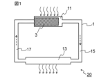
- FIG. 1 is a schematic cross-sectional view of a heat transport device in one embodiment of the present disclosure.
- 1 shows an XRD pattern of the material (TiCO) manufactured in Example 1.
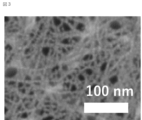
- An FE-SEM image of the material (TiCO) produced in Example 1 is shown.
- wick means a member used for heat transport. More specifically, “wick” refers to a member capable of transporting a working fluid in a liquid state by capillary force.
- the wick includes a material containing nanofibers and/or a two-dimensional substance.
- the term “material” simply means "a material containing nanofibers and/or a two-dimensional substance” (in other words, a material containing at least one of nanofibers and a two-dimensional substance).
- the material containing nanofibers and/or two-dimensional substances typically means a material that is solid and does not contain a binder or the like (for example, a polymer).
- a material containing nanofibers and/or a two-dimensional substance is, in a narrow sense, a material that essentially consists of at least one of nanofibers and a two-dimensional substance (including other objects or impurities that may be unavoidably mixed). good).
- materials including nanofibers and/or two-dimensional substances are not limited thereto.
- the material contained in the wick of this embodiment is a nanofiber (or nanofilament, hereinafter the same) of a predetermined material (substance) and/or a two-dimensional substance.
- the predetermined material that can be used in this embodiment is represented by the following formula (1).
- MQ a O b ...(1) (wherein, M is at least one element selected from the group consisting of groups 3, 4, 5, 6 and 7, and includes so-called early transition metals, such as Sc, Ti, Zr, Hf, V, Nb , Ta, Cr, Mo and Mn, preferably at least one element selected from the group consisting of Ti, V, Cr, Mo and Mn.
- Gain, Q is at least one element selected from the group consisting of Groups 12, 13, 14, 15 and 16 (excluding O), for example consisting of B, C, N, Si, P and S. may contain at least one element selected from the group; a is 0 or more and 2 or less, b is greater than 0 and less than or equal to 2)
- MQO predetermined material
- MQOs include materials represented by the formulas TiO 2 , TiCO, TiCON, VO 2 , VCO, VCON, CrO 2 , CrCO, CrCON, MoO 2 , MoCO, MoCON, MnO 2 , MnCO, MnCON, etc. It will be done.
- the M may be Ti and the Q may be C.
- a may be other than 0.
- the above-mentioned predetermined material may have a peak in the diffraction angle 2 ⁇ in the range of 2° or more and 10° or less in an X-ray diffraction (XRD) pattern.
- XRD X-ray diffraction
- MQO has a crystal structure different from a hexagonal system.
- the crystal structure of MQO can be considered to be anatase type, lepidocrocite type, or a mixture thereof at present.
- the crystal structure of MQO may be lepidocrocite type.
- MQO can be produced using the first raw material and the second raw material, for example, as follows.
- the first raw material contains at least the above M
- the second raw material contains at least the above Q
- the first raw material and the second raw material can react in a protic solvent to generate MQO.
- a material represented by the following formula (2) may be used as the first raw material.
- M c A 1 d ...(2) (In the formula, M is as above, A1 is at least one element selected from the group consisting of Groups 12, 13, 14, 15 and 16, for example selected from the group consisting of B, C, N, O, Si, P and S. may contain at least one element, c and d are each independently from 1 to 5)
- the material represented by formula (2) needs to be different from the MQO of the product.
- the material represented by formula (2) typically does not have a peak in the diffraction angle 2 ⁇ of 2° or more and 10° or less in an X-ray diffraction (XRD) pattern.
- XRD X-ray diffraction
- Examples of the first raw material represented by formula (2) include TiB 2 , TiB, TiC, TiN, TiO 2 , Ti 5 Si 3 , Ti 2 SbP, VO 2 , V 2 O 4 , NbC, Nb 2 O 5 , MoO 2 , MoO 3 , MoS 2 , MnO 2 , Mn 3 O 4 , MnCO 3 and the like.
- a material represented by the following formula (3) may be used as the first raw material.
- M m A 2 X n ...(3) (In the formula, M is as above, X is at least one element selected from the group consisting of C and N, n is 1 or more and 4 or less, m is greater than n and less than or equal to 5, A 2 is at least one element selected from the group consisting of Groups 12, 13, 14, 15 and 16, usually a Group A element, typically Group IIIA and Group IVA, and more details may contain at least one selected from the group consisting of Al, Ga, In, Tl, Si, Ge, Sn, Pb, P, As, S and Cd, preferably Al)
- the MAX phase has a layer composed of two A atoms located between two layers represented by M m X n (which may have a crystal lattice in which each X is located in an octahed
- a 2 atomic layer a layer of A 2 atoms
- the MAX phase is not limited to this.
- Examples of the first raw material represented by formula (3) include Ti 3 AlC 2 , Ti 3 GaC 2 , Ti 3 SiC 2 and the like.
- the material represented by formula (2) and the material represented by formula (3) may be used together (for example, as a mixture).
- An ion-binding substance having a carbon-containing group may be used as the second raw material.
- the ion-binding substance having a carbon-containing group contains C.
- Examples of the ion-binding substance include ammonium salts, phosphates, sulfates, and the like.
- a quaternary ammonium salt may be used as the second raw material.
- quaternary ammonium salts include tetramethylammonium hydroxide (TMAH), tetraethylammonium hydroxide (TEAH), tetrapropylammonium hydroxide (TPAH), tetrabutylammonium hydroxide (TBAH or TBAOH), benzyltrimethylammonium Hydroxide, Tetrabutylammonium Fluoride (TBAF), Tetrabutylammonium Chloride (TBACl), Tetrabutylammonium Bromide (TBAB), Tetrabutylammonium Iodide (TBAI), Benzyltriethylammonium Chloride (BTEAC), Hexadecyltrimethylammonium Bromide , cetyltrimethylammonium bromide (CTAB), benzethonium chloride, benzalkonium chloride, cetylpyridin
- ion-binding substances containing P and/or S may be used as the second raw material.
- the protic solvent may be any solvent as long as it can at least partially dissolve the first raw material and the second raw material, and in particular may be an aqueous solvent.
- aqueous solvent water, alcohol (eg, ethanol, 1-propanol, isopropanol), carboxylic acid (eg, acetic acid, formic acid), etc. are used.
- the aqueous solvent may be composed of water and optionally a liquid substance that is compatible with water (eg, a protic solvent other than water), and is preferably water.
- the first raw material and the second raw material are reacted in a protic solvent.
- the second raw material may be added to the protic solvent in advance.
- the proportion of the second raw material to the total of the protic solvent and the second raw material can be, for example, 5% by mass or more, especially 20% by mass or more, and/or can be, for example, 80% by mass or less, especially 50% by mass or less.
- the first raw material may be further added to the protic solvent to which the second raw material has been added and mixed. In such a mixture, the reaction that produces MQO proceeds.
- the temperature of the mixture (which may contain reaction products) (reaction temperature) may be, for example, 15° C. or higher, especially 40° C. or higher, and/or for example 100° C.
- the mixing time may be, for example, one or more days, especially two or more days, and/or it may be, for example, no more than 10 days, especially no more than 7 days.
- Mixing can be carried out, for example, by rotating and stirring a magnetic stirrer placed in a container while maintaining the reaction temperature with a hot plate stirrer and a hot water bath.
- the treatment operations and conditions that allow the reaction to proceed are not limited to those described above, and may be appropriately selected depending on the first raw material, second raw material, protic solvent, etc. to be used.
- MQO MQO
- the resulting MQO nanofibers can be in the form of nanoribbons extending in nanoscale width.
- a plurality of MQO nanofibers may be bonded and/or integrated with each other to grow into two-dimensionally extending nanoflakes.
- a plurality of MQO nanoflakes may overlap each other (eg, due to van der Waals forces) to form a laminate.
- the generation and growth of such MQO may be considered to be due to a bottom-up synthetic reaction (see, for example, Non-Patent Document 1).
- MQO is solid content.
- MQOs may typically be particles (or powders).
- the mixture after the reaction may be subjected to post-treatment as appropriate.
- post-treatments include, for example, washing, impact application (including application of shear force), drying (for example, freeze drying, heat drying), pulverization, and the like.
- Washing may be performed using a protic solvent. Similar explanations as above may apply for protic solvents, which may be washed with water or alcohol, for example. After washing, separation operations (centrifugation and/or decantation) may be performed. The washing and separation operations can be repeated until the pH of the supernatant after centrifugation becomes, for example, 8 or less.
- cleaning may be performed using an aqueous solution of a metal salt.
- the metal salt can be, for example, a halide (fluoride, chloride, bromide, iodide) of an alkali metal (Li, Na, K, etc.), typically LiCl, NaCl, KCl, etc.
- cleaning may be carried out using, for example, an aqueous metal salt solution having a concentration of 1 to 10 molar.
- separation operations centrifugation and/or decantation
- the washing and separation operations can be repeated as necessary until the pH of the supernatant after centrifugation becomes, for example, 8 or less.
- Shocks such as vibration and/or ultrasound may be applied during and/or after cleaning. This can promote the dispersion of MQO particles (for example, nanofibers/nanoflakes, hereinafter the same). If the MQO particles are aggregated, they can be disintegrated. Such an effect is significantly obtained when impact is applied during cleaning using an aqueous solution of a metal salt (it is thought that the metal cations derived from the metal salt can enter the gaps between the aggregates and disintegrate them). Shock can be applied using, for example, one or more of a handshake, an automatic shaker, a mechanical shaker, a vortex mixer, a homogenizer, an ultrasonic bath, and the like.
- a separation operation can be performed at any appropriate timing to remove unnecessary liquid components if present.
- a drying operation typically freeze-drying or thermal drying, may be carried out. Freeze-drying can be performed, for example, by freezing a mixture containing particles of MQO and a liquid component at any suitable temperature (eg, ⁇ 40° C.) and then drying it under a reduced pressure atmosphere. Thermal drying can be carried out, for example, by drying a mixture containing MQO particles and a liquid component at a temperature of 25° C. or higher (for example, 200° C. or lower) under normal pressure or a reduced pressure atmosphere.
- the pulverization can be carried out using, for example, a mortar and pestle combination, an IKA mill, etc., but is not particularly limited. Grinding may be carried out after drying.
- particles of MQO can be obtained as a material containing MQO.
- MQO particles for example, nanofibers (and in some cases, aggregates of MQO nanofibers, such as MQO nanoflakes, which are also collectively referred to as "MQO nanofibers, etc.") can be obtained.
- MQO is represented by formula (1)
- the material containing MQO does not need to consist only of the constituent elements of formula (1).
- the MQO-containing material may optionally include protons and/or metal cations.
- the MQO-containing material may optionally have a modification or termination T present on its surface selected from the group consisting of hydroxyl groups, chlorine atoms, oxygen atoms, and hydrogen and nitrogen atoms. It may have at least one kind.
- a material containing MQO may have two or more layers between which ammonium ions (e.g., quaternary ammonium cations) and metal cations ( For example, at least one selected from the group consisting of alkali metal ions and alkaline earth metal ions may be present.
- ammonium ions e.g., quaternary ammonium cations
- metal cations For example, at least one selected from the group consisting of alkali metal ions and alkaline earth metal ions may be present.
- Materials containing MQO may contain unreacted first raw materials and/or second raw materials as impurities, and may also contain substances derived from the first raw materials, second raw materials, and/or protic solvents. may include.
- N may exist (remain) in any form in the material containing MQO, such as MQO nanofibers.
- the material containing MQO may include ammonium ions and tetramethylammonium ions.
- the material containing MQO contains a relatively small amount of residual A atoms, for example, 10% by mass or less with respect to the original A atoms. Good too.
- the residual amount of A atoms may be preferably 8% by mass or less, more preferably 6% by mass or less. However, even if the residual amount of A atoms exceeds 10% by mass, there may be no problem depending on the usage conditions.
- Such a supernatant liquid can be made into a slurry containing MQO particles such as MQO nanofibers by directly diluting it with a liquid medium, or by mixing it with a liquid medium after drying.
- the wick of this embodiment can be manufactured by shaping (molding, cutting, etc.) a material containing MQO, such as MQO nanofibers, into a desired shape and size using any appropriate method.
- the wick of this embodiment may be a fibrous structure formed using MQO nanofibers or the like.
- Such fibrous structures can be produced, for example, by applying a slurry containing nanofibers of MQO onto a substrate by any suitable method (e.g., filtration, spraying, bar coating, spin coating, dipping, etc.), drying, and then It can be manufactured by removing the base material.
- the liquid medium contained in the slurry can be selected as appropriate, and includes, for example, protic solvents (the same explanations as above apply), aprotic solvents (such as tetrahydrofuran, methylene chloride, acetonitrile, acetone, N, N- (dimethylformamide, dimethyl sulfoxide, etc.), nonpolar solvents (eg, hexane, benzene, toluene, diethyl ether, chloroform, ethyl acetate), and the like.
- protic solvents such as tetrahydrofuran, methylene chloride, acetonitrile, acetone, N, N- (dimethylformamide, dimethyl sulfoxide, etc.
- nonpolar solvents eg, hexane, benzene, toluene, diethyl ether, chloroform, ethyl acetate
- the wick of this embodiment is obtained.
- the shape and dimensions of the wick of this embodiment can be appropriately selected depending on the desired use.
- a material containing MQO typically has a peak in the diffraction angle 2 ⁇ of 2° or more and 10° or less in an X-ray diffraction (XRD) pattern.
- XRD X-ray diffraction
- a c-axis oriented MQO membrane is installed in the XRD analyzer (for example, as in the example described later, the filter is removed after suction filtration). It is preferable to measure the self-supporting membrane obtained by arranging the surface that was in contact with the filter on the lower side.
- the material of this embodiment (more specifically, MQO) has a Raman shift of at least 275 to 295 cm -1 , 435 to 295 cm -1 in a Raman spectrum using a laser with a wavelength of 514 nm, although this embodiment is not limited to It may have peaks at 455 cm ⁇ 1 and 665 to 745 cm ⁇ 1 .
- the material of this embodiment (more specifically, MQO) has a Raman shift of 140 to 160 cm -1 and 275 to 295 cm in a Raman spectrum using a laser with a wavelength of 514 nm. -1 , 435-455 cm -1 , and 665-745 cm -1 .
- 140 to 160 cm ⁇ 1 is an anatase type peak.
- the material of this embodiment (more specifically, MQO) has a crystal structure of anatase type, lepidocrocite type, or a mixture of these, although the present embodiment is not limited thereto. More preferably, it has a lepidocrocite crystal structure.
- the material of this embodiment (more specifically, MQO) has a Raman shift of at least 275 to 295 cm -1 , 435 to 295 cm -1 in a Raman spectrum using a laser with a wavelength of 514 nm, although this embodiment is not limited to It may have peaks at 455 cm -1 and 665 to 745 cm -1 , and when the intensity of each peak is X, Y, and Z, X is the largest.
- the material of this embodiment (more specifically, MQO) has a Raman shift of at least 180 to 200 cm ⁇ 1 in a Raman spectrum using a laser with a wavelength of 514 nm,
- a Raman shift of at least 180 to 200 cm ⁇ 1 in a Raman spectrum using a laser with a wavelength of 514 nm When there are peaks at the positions of 275 to 295 cm -1 , 375 to 395 cm -1 , 435 to 455 cm -1 , and 665 to 745 cm -1 and the intensities of each peak are V, X, Y, Z, and W. It may take the form that X is the largest.
- the Raman spectrum is measured with a Raman spectrometer using a laser beam with a wavelength of 514 nm as an excitation light source (the vertical axis is intensity and the horizontal axis is Raman shift). Peaks in a Raman spectrum can be identified visually or using software used with a Raman spectrometer.
- the particle size of the particles of MQO can be, for example, 0.01 nm or more, especially 0.1 nm or more, even 1 nm or more, and/or can be, for example, less than 1000 nm, especially 100 nm or less, and even 50 nm or less. Such particles may also be referred to as nanoparticles.
- the particle morphology of MQO is nanofibers and/or two-dimensional materials.
- the two-dimensional material includes one or more of nanoflakes and laminates of nanoflakes. In this embodiment, the two-dimensional material is not limited to only nanoflakes and a laminate of nanoflakes.
- a material comprising MQO typically particles (e.g. nanofibers/nanoflakes) of MQO, e.g. nanofibers of MQO (and optionally aggregates of nanofibers of MQO, e.g. nanoflakes of MQO) ) is provided.
- MQO nanofibers have a hydrophilic surface and have nano-order cross-sectional dimensions.
- a wick containing such MQO nanofibers has a large ability to attract (e.g., suck up) a working fluid in a liquid state by capillary action, and therefore can transfer (e.g., suck up) a working fluid in a liquid state at a high speed. .
- the reason for this is that due to the nano-order cross-sectional dimensions, the volume density of the nanofibers in the wick is high, and the gaps between the nanofibers form a narrow space (flow path for the working fluid).
- the total surface area of the nanofibers obtained is large, and the hydrophilic surface makes it easier for a working fluid in a liquid state (typically, but not limited to, water) to wet and spread on the surface of the MQO nanofibers. This may be possible.
- nanofiber of MQO is a solid substance extending in the longitudinal direction, and the external dimensions of a cross section perpendicular to the longitudinal direction (cross-sectional external dimensions) are nano-order (i.e., 1 nm or more and 1000 nm or more). (less than 1 nm) or smaller than that (less than 1 nm, for example, 0.1 nm or more and less than 1 nm).
- the length of the MQO nanofibers in the longitudinal direction is not particularly limited. That is, the length of the nanofiber in the longitudinal direction is not limited to nano-order (ie, 1 nm or more and less than 1000 nm), but may be micron-order (1 ⁇ m or more and less than 1000 ⁇ m).
- the cross-sectional dimensions of the nanofibers can be, for example, 0.1 nm or more, especially 1 nm or more, and for example 100 nm or less, especially 50 nm or less, preferably 15 nm or less.
- a wick including MQO nanofibers or the like having such a small cross-sectional dimension can transport a working fluid in a liquid state at a higher velocity.
- MQO nanofibers having such small cross-sectional dimensions can be realized.
- the cross-sectional external dimensions of the MQO nanofibers mean the shortest distance passing through the center in a cross section that traverses the longitudinal direction of the MQO nanofibers.
- the shape of the cross section of the MQO nanofiber is not particularly limited, but may be approximated by, for example, a rectangle (rectangle, square, etc.) or an ellipse (oblate circle, perfect circle, etc.).
- the MQO nanofiber is in the form of a nanoribbon
- its cross-sectional shape can be approximated by a rectangle
- the cross-sectional external dimension can correspond to the short side length of the rectangle.
- the MQO nanofiber is in the form of a nanofilament
- its cross-sectional shape can be approximated by a flat circle
- the cross-sectional external dimensions can correspond to the short axis length of the flat circle.
- the BET specific surface area of a material containing MQO such as MQO nanofibers is not particularly limited, but may be, for example, 10 m 2 /g or more and 500 m 2 /g or less.
- BET specific surface area is the isothermal adsorption curve of nitrogen gas or other gases mentioned above under liquid nitrogen temperature (77 K) by an adsorption method using nitrogen gas or other suitable gas (e.g. krypton (Kr) gas, etc.). It is calculated using the BET formula.
- a "two-dimensional substance” has a two-dimensionally extending surface (also referred to as a plane or two-dimensional sheet surface), and the maximum dimension of the surface (which may correspond to the "in-plane dimension" of a particle) ), the thickness of which is nano-order (i.e., 1 nm or more and less than 1000 nm) or smaller sub-nano order (less than 1 nm, e.g. 0.1 nm or more and less than 1 nm). mean something
- the in-plane dimension is not limited to nano-order (ie, 1 nm or more and less than 1000 nm), but may be micron-order (1 ⁇ m or more and less than 1000 ⁇ m).
- the two-dimensional material includes one or more of nanoflakes and nanoflake stacks, as described above. Nanoflakes may also be referred to as nanosheets or two-dimensional (nano)sheets.
- the thickness of one layer of nanoflakes can be, for example, 0.01 nm or more, especially 0.8 nm or more, and eg 20 nm or less, especially 3 nm or less.
- the in-plane dimensions of the nanoflakes may be, for example, 0.1 ⁇ m or more, especially 1 ⁇ m or more, and for example 200 ⁇ m or less, especially 40 ⁇ m or less. Nanoflakes can be constructed by aggregating nanofibers.
- a stack of nanoflakes may also be referred to as a multilayer MQO.
- the distance (interlayer distance or void size) between two adjacent nanoflakes (or two adjacent layers of MQO) is not particularly limited.
- the above-mentioned dimensions are calculated using a scanning electron microscope (SEM), a transmission electron microscope (TEM), or an atomic force microscope (processed by a method such as a focused ion beam (FIB), if necessary).
- SEM scanning electron microscope
- TEM transmission electron microscope
- FIB focused ion beam
- real space calculated from the number average dimension (number average of at least 40) based on photographs observed with AFM) or the position on the reciprocal lattice space of the (002) plane measured by X-ray diffraction (XRD) method. It can be determined as a distance.
- XRD X-ray diffraction
- the cross-sectional external dimensions of MQO nanofibers are determined by exposing the cross-section of a wick containing MQO nanofibers using a method such as a focused ion beam (FIB), and then using a scanning electron microscope (SEM) or a transmission electron microscope (SEM) to examine the exposed cross-section. Take an image using a TEM, extract at least 40 MQO nanofibers in which a cross section crossing the longitudinal direction appears, and calculate the number average of their cross-sectional external dimensions. is required.
- FIB focused ion beam
- SEM scanning electron microscope
- SEM transmission electron microscope
- MQO is not limited to the above forms, but may have any suitable form.
- a heat transport device refers to a device that transports heat using a phase change of a working fluid.
- Phase change of the working fluid refers to evaporation and condensation.
- the heat transport device 20 of the present embodiment includes: A housing 1 having a space inside; A wick 3 disposed within the housing 1; A working fluid (not shown) sealed in the housing 1 in a state where it can come into contact with the wick 3; including.
- a working fluid (not shown) sealed in the housing 1 in a state where it can come into contact with the wick 3; including.
- the wick 3 the one described above in the first embodiment is used.
- FIG. 1 exemplarily shows a case where the heat transport device 20 is a loop-type heat pipe.
- the housing 1 includes an evaporator 11, a condenser 13, and a gas flow path 15 and a liquid flow path 17 that connect these, respectively.
- the passage 15 and the liquid flow passage 17 integrally constitute the internal space of the housing 1 .
- the wick 3 is placed within the evaporator 11.
- a working fluid (not shown) is sealed in the internal space of the housing 1 .
- the housing 1 is made of a thermally conductive material (for example, metal) at least in the evaporator 11 and the condenser 13.
- the working fluid is evaporated in the evaporator 11 (relatively high temperature part) to which heat is supplied from the outside (heat source), and the working fluid in a gaseous state moves in the gas flow path 15,
- the condenser 13 a relatively low-temperature part
- heat is released to the outside, and the working fluid, which has become a liquid, passes through the liquid flow path 17 to the evaporator 11 due to the capillary force of the wick 3. be transported (returned).
- the working fluid circulates within the housing 1 while changing its phase.
- the flow of the working fluid is schematically shown by dotted line arrows
- the supply of heat from the outside (heat input) and the radiation of heat to the outside (thermal output) are schematically shown by dotted line arrows.
- the working fluid in the liquid state can be transported at a high speed, and high heat transport performance can be obtained. , the maximum heat transport amount of the heat transport device 20 is improved.
- FIG. 1 shows a case where the heat transport device 20 is a loop-type heat pipe, but the heat transport device of this embodiment uses no wick except for using the wick 3 described above in Embodiment 1.
- the structure of a known heat transport device for example, a tubular heat pipe, a vapor chamber, etc. may be applied.
- the wick and the heat transport device in an embodiment of the present disclosure have been described above in detail, the present disclosure can be modified in various ways. Note that the wick of the present disclosure may be manufactured by a method different from the manufacturing method in the embodiments described above.
- Example 1 relates to the wick of Embodiment 1, which uses TiCO nanofibers.
- ⁇ Preparation of slurry containing TiCO nanofibers First, in a container (100 mL Eyeboy), 1 g of titanium diboride (TiB 2 , manufactured by Alfa Aesar) and 30 mL of a 25% by mass tetramethylammonium hydroxide (TMAH) aqueous solution (Tokyo (manufactured by Kasei Kogyo Co., Ltd.). A stirrer tip with a length approximately the same size (35 mm) as the inner diameter of the circular bottom of the container was placed there. While keeping the container at 50° C. in a water bath, the mixture in the container was stirred with a stirrer tip and maintained for 120 hours, thereby allowing the reaction to proceed.
- TMAH tetramethylammonium hydroxide
- the reaction mixture in the container was then transferred to a 50 mL centrifuge tube with a stainless steel spatula (without adding any liquid medium such as ethanol or water). Centrifugation was performed using a centrifuge at 3500 G for 5 minutes to sediment the solid content. (i) After centrifugation, discard the supernatant, (ii) add 40 mL of ethanol (manufactured by Fujifilm Wako Pure Chemical Industries, Ltd.) to the remaining sediment in the centrifuge tube, and handshake for 5 minutes (reslurry). (iii) Centrifugation was performed under the same conditions as above. These operations (i) to (iii) were repeated until the pH of the supernatant liquid became 8 or less.
- the pH of the supernatant liquid became 8 or less, so the supernatant liquid was discarded and the repeating operation was completed.
- 40 mL of pure water was added to the remaining sediment in the centrifuge tube, and the mixture was shaken and stirred for 15 minutes using an automatic shaker. Thereafter, centrifugation was performed using a centrifuge at 3500 G for 30 minutes, and the supernatant was collected as a sample slurry.
- the sample slurry obtained corresponds to a slurry containing TiCO nanofibers (see analysis results below).
- the wick sample prepared above was placed in a petri dish filled with water with the WT surface (1 cm x 100 ⁇ m) vertically placed on the top and bottom surfaces, and placed at a depth of about 1 mm. When it was soaked in water, water was sucked up to the top surface at a speed of 4 mm/s. From this result, the volume of water sucked up by the wick sample per unit area per unit time is 4 ⁇ 10 -3 m 3 /(m 2 s), and therefore the mass of water sucked up per unit area per unit time is , 4 kg/(m 2 ⁇ s) (specific gravity of water: 1000 kg/m 3 ). Since the heat of evaporation of water per unit mass at 25° C.
- the amount of heat that this wick sample can take away by evaporating water at 25° C. is calculated to be 9768 kW/m 2 . That is, in the wick sample of Example 1, the water transport speed was 4 mm/s, and the water heat transport performance at 25° C. was about 10 4 kW/m 2 .
- FIG. 3 shows an FE-SEM image. As can be seen from Figure 3, this material had a cross-sectional profile of approximately 5 nm.
- Comparative Example 1 relates to a wick using particles of MXene, which is a type of two-dimensional material.
- MAX particles precursor of MXene particles
- TiC powder, Ti powder, and Al powder all manufactured by Kojundo Kagaku Kenkyusho Co., Ltd.
- Al powder all manufactured by Kojundo Kagaku Kenkyusho Co., Ltd.
- the mixture was added and mixed for 24 hours.
- the obtained mixed powder was fired at 1350° C. for 2 hours in an Ar atmosphere.
- the fired body (block) thus obtained was ground with an end mill to a maximum size of 40 ⁇ m or less.
- Ti 3 AlC 2 particles were obtained as MAX particles.
- etching was performed under the following etching conditions to obtain a solid-liquid mixture (slurry) containing a solid component derived from the Ti 3 AlC 2 powder.
- Etching conditions ⁇ Precursor: Ti 3 AlC 2 (passed through a 45 ⁇ m sieve) ⁇ Etching solution composition: 49%HF 6mL 18 mL H2O HCl (12M) 36mL ⁇ Precursor input amount: 3.0g ⁇ Etching container: 100mL Eye Boy ⁇ Etching temperature: 35°C ⁇ Etching time: 24h ⁇ Stirrer rotation speed: 400 rpm
- the slurry was divided into two parts, inserted into two 50 mL centrifuge tubes, centrifuged at 3500 G using a centrifuge, and then the supernatant liquid was discarded.
- the operation of adding 40 mL of pure water to the remaining precipitate in each centrifuge tube, performing centrifugation again at 3500 G, and separating and removing the supernatant liquid was repeated 11 times. After the final centrifugation, the supernatant was discarded and the Ti 3 C 2 T x -water medium clay was obtained.
- this supernatant liquid was centrifuged using a centrifuge at 4300G for 2 hours, the supernatant liquid was discarded, and a single-layer/poor-layer MXene-containing clay was prepared as a mono-layer/poor-layer MXene-containing sample. I got it.
- the wick sample prepared above was placed in a petri dish filled with water with the WT surface (1 cm x 100 ⁇ m) vertically placed on the top and bottom surfaces, and placed at a depth of about 1 mm. When it was soaked in water, it was unable to absorb water at all (the suction height was 0 mm).
- Comparative Example 2 relates to a wick using a sintered body (porous metal sintered body) of metal powder (copper powder).
- wick Copper powder with an average particle size D50 of 50 ⁇ m was used as the metal powder, and acrylic resin (binder) and copper powder were mixed at a volume ratio of 1:1.
- the resulting mixture was heat treated at 400° C. for 1 hour to burn off the acrylic resin and obtain a porous metal sintered body.
- the obtained porous metal sintered body was cut to obtain a wick sample having a width (W) of 1 cm, a length (L) of 2 cm, and a thickness (T) of 100 ⁇ m.
- wick sample prepared above was placed in a petri dish filled with water with the WT surface (1 cm x 100 ⁇ m) vertically placed on the top and bottom surfaces, and placed at a depth of about 1 mm. When it was soaked in water, water was sucked up to the top surface at a speed of 0.5 mm/s. From this result, the wick sample of Comparative Example 2 has a water transfer rate of 0.5 mm/s, and according to the same calculation as Example 1, the water heat transfer performance at 25°C is approximately 10 3 kW/m. It was 2 .
- Comparative Example 3 relates to a wick using a sintered body (porous metal sintered body) of metal powder (titanium powder).
- the wick of the present disclosure can be used in a heat transport device that utilizes phase change of a working fluid to transport the working fluid by capillary force.
- the heat transport device of the present disclosure can be incorporated into an electronic device and used to release (remove) heat from a heat source of the electronic device.
- the wick and heat transport device of the present disclosure can be used not only in these applications but also in any suitable application.
- a wick used for heat transport The formula below: MQ a O b (wherein M is at least one element selected from the group consisting of Groups 3, 4, 5, 6, and 7; Q is at least one element selected from the group consisting of Groups 12, 13, 14, 15 and 16 (excluding O), a is 0 or more and 2 or less, b is greater than 0 and less than or equal to 2)
- a heat transport device that utilizes phase change of a working fluid A housing having a space inside; The wick according to any one of ⁇ 1> to ⁇ 3>, disposed within the housing; a working fluid sealed within the housing so as to be in contact with the wick; heat transport equipment, including
Landscapes
- Engineering & Computer Science (AREA)
- Life Sciences & Earth Sciences (AREA)
- Sustainable Development (AREA)
- Physics & Mathematics (AREA)
- Thermal Sciences (AREA)
- Mechanical Engineering (AREA)
- General Engineering & Computer Science (AREA)
- Chemical & Material Sciences (AREA)
- Chemical Kinetics & Catalysis (AREA)
- General Chemical & Material Sciences (AREA)
- Textile Engineering (AREA)
- Physical Or Chemical Processes And Apparatus (AREA)
Abstract
L'invention concerne une mèche utilisée pour transporter de la chaleur, la mèche contenant des matériaux comprenant des nanofibres et/ou une substance bidimensionnelle d'un matériau représenté par la formule MQaOb (M représentant au moins un élément choisi dans le groupe constitué des groupes 3, 4, 5, 6 et 7, Q représentant au moins un élément [à l'exclusion de O] choisi dans le groupe constitué des groupes 12, 13, 14, 15 et 16, a étant supérieur ou égal à 0 et inférieur ou égal à 2, et b étant supérieur ou égal à 0 et inférieur ou égal à 2).
Applications Claiming Priority (2)
| Application Number | Priority Date | Filing Date | Title |
|---|---|---|---|
| JP2022-079566 | 2022-05-13 | ||
| JP2022079566 | 2022-05-13 |
Publications (1)
| Publication Number | Publication Date |
|---|---|
| WO2023219168A1 true WO2023219168A1 (fr) | 2023-11-16 |
Family
ID=88730395
Family Applications (1)
| Application Number | Title | Priority Date | Filing Date |
|---|---|---|---|
| PCT/JP2023/017973 WO2023219168A1 (fr) | 2022-05-13 | 2023-05-12 | Mèche et dispositif de transport de chaleur |
Country Status (1)
| Country | Link |
|---|---|
| WO (1) | WO2023219168A1 (fr) |
Citations (7)
| Publication number | Priority date | Publication date | Assignee | Title |
|---|---|---|---|---|
| JPS53145471U (fr) * | 1977-04-19 | 1978-11-16 | ||
| US20060151153A1 (en) * | 2005-01-07 | 2006-07-13 | Hon Hai Precision Industry Co., Ltd. | Heat dissipation system |
| JP2006348346A (ja) * | 2005-06-16 | 2006-12-28 | Nissan Motor Co Ltd | 吸水材、熱伝導部材、及びその製造方法 |
| US20100200199A1 (en) * | 2006-03-03 | 2010-08-12 | Illuminex Corporation | Heat Pipe with Nanostructured Wick |
| JP2015169411A (ja) * | 2014-03-10 | 2015-09-28 | 富士通株式会社 | 熱輸送デバイスとその製造方法、及び電子機器 |
| US20200149820A1 (en) * | 2014-11-04 | 2020-05-14 | Roccor, Llc | Conformal thermal ground planes |
| US20200340756A1 (en) * | 2019-04-26 | 2020-10-29 | Nanotek Instruments, Inc. | Graphene-enhanced vapor-based heat transfer device |
-
2023
- 2023-05-12 WO PCT/JP2023/017973 patent/WO2023219168A1/fr unknown
Patent Citations (7)
| Publication number | Priority date | Publication date | Assignee | Title |
|---|---|---|---|---|
| JPS53145471U (fr) * | 1977-04-19 | 1978-11-16 | ||
| US20060151153A1 (en) * | 2005-01-07 | 2006-07-13 | Hon Hai Precision Industry Co., Ltd. | Heat dissipation system |
| JP2006348346A (ja) * | 2005-06-16 | 2006-12-28 | Nissan Motor Co Ltd | 吸水材、熱伝導部材、及びその製造方法 |
| US20100200199A1 (en) * | 2006-03-03 | 2010-08-12 | Illuminex Corporation | Heat Pipe with Nanostructured Wick |
| JP2015169411A (ja) * | 2014-03-10 | 2015-09-28 | 富士通株式会社 | 熱輸送デバイスとその製造方法、及び電子機器 |
| US20200149820A1 (en) * | 2014-11-04 | 2020-05-14 | Roccor, Llc | Conformal thermal ground planes |
| US20200340756A1 (en) * | 2019-04-26 | 2020-10-29 | Nanotek Instruments, Inc. | Graphene-enhanced vapor-based heat transfer device |
Similar Documents
| Publication | Publication Date | Title |
|---|---|---|
| Lambert et al. | Synthesis and characterization of titania− graphene nanocomposites | |
| Anwer et al. | Nature-inspired, graphene-wrapped 3D MoS2 ultrathin microflower architecture as a high-performance anode material for sodium-ion batteries | |
| US11139473B2 (en) | Porous silicon compositions and devices and methods thereof | |
| Wang et al. | Fabrication and thermal stability of two-dimensional carbide Ti3C2 nanosheets | |
| JP5937653B2 (ja) | 炭素材料及びその製造方法 | |
| Moghaddam et al. | Preparation, characterization, and rheological properties of graphene–glycerol nanofluids | |
| von Treifeldt et al. | The effect of Ti3AlC2 MAX phase synthetic history on the structure and electrochemical properties of resultant Ti3C2 MXenes | |
| JP6858175B2 (ja) | ケイ素‐炭素複合粒子材料 | |
| Ai et al. | Formation of graphene oxide gel via the π-stacked supramolecular self-assembly | |
| JP5763741B2 (ja) | 酸化グラフェンおよび四価バナジウムオキソ水酸化物の自己組織化複合体 | |
| WO2012165753A1 (fr) | Procédé de fabrication de graphène par exfoliation chimique | |
| JP6724242B2 (ja) | Si/C複合粒子の製造 | |
| US10629900B2 (en) | Porous silicon compositions and devices and methods thereof | |
| US20230242407A1 (en) | Conductive two-dimensional particle and method for producing same, conductive film, conductive composite material, and conductive paste | |
| Wu et al. | Hemicellulose-triggered high-yield synthesis of carbon dots from biomass | |
| Jia et al. | Electrochemical probing of carbon quantum dots: not suitable for a single electrode material | |
| Roy et al. | Investigating suitable medium for the long-duration storage of Ti2CTx MXene | |
| WO2023219168A1 (fr) | Mèche et dispositif de transport de chaleur | |
| WO2022050114A1 (fr) | Particules bidimensionnelles électro-conductrices et leur procédé de fabrication | |
| US20170214039A1 (en) | Method for carbon coating on electrode active material of lithium ion battery | |
| Wang et al. | A bio-inspired MXene/quaternary chitosan membrane with a “brick-and-mortar” structure towards high-performance photothermal conversion | |
| Naboka et al. | Practical Approach to Enhance Compatibility in Silicon/Graphite Composites to Enable High-Capacity Li-Ion Battery Anodes | |
| Keshari et al. | Amorphous MnO x Nanostructure/Multiwalled Carbon Nanotube Composites as Electrode Materials for Supercapacitor Applications | |
| EP2755259A1 (fr) | Composites auto-assemblés d'oxyde de graphène et de H4V3O8 | |
| WO2024053514A1 (fr) | Matériau contenant des nano-flocons de substance bidimensionnelle et sa méthode de production |
Legal Events
| Date | Code | Title | Description |
|---|---|---|---|
| 121 | Ep: the epo has been informed by wipo that ep was designated in this application |
Ref document number: 23803642 Country of ref document: EP Kind code of ref document: A1 |