WO2023219168A1 - Wick and heat transport device - Google Patents
Wick and heat transport device Download PDFInfo
- Publication number
- WO2023219168A1 WO2023219168A1 PCT/JP2023/017973 JP2023017973W WO2023219168A1 WO 2023219168 A1 WO2023219168 A1 WO 2023219168A1 JP 2023017973 W JP2023017973 W JP 2023017973W WO 2023219168 A1 WO2023219168 A1 WO 2023219168A1
- Authority
- WO
- WIPO (PCT)
- Prior art keywords
- wick
- mqo
- nanofibers
- less
- heat transport
- Prior art date
Links
- 239000000463 material Substances 0.000 claims abstract description 65
- 239000002121 nanofiber Substances 0.000 claims abstract description 65
- 239000000126 substance Substances 0.000 claims abstract description 25
- 239000012530 fluid Substances 0.000 claims description 37
- 238000002441 X-ray diffraction Methods 0.000 claims description 19
- 239000000203 mixture Substances 0.000 claims description 16
- 239000013078 crystal Substances 0.000 claims description 10
- 238000001069 Raman spectroscopy Methods 0.000 claims description 9
- 238000001237 Raman spectrum Methods 0.000 claims description 8
- 230000008859 change Effects 0.000 claims description 8
- AEIXRCIKZIZYPM-UHFFFAOYSA-M hydroxy(oxo)iron Chemical compound [O][Fe]O AEIXRCIKZIZYPM-UHFFFAOYSA-M 0.000 claims description 6
- GWEVSGVZZGPLCZ-UHFFFAOYSA-N Titan oxide Chemical compound O=[Ti]=O GWEVSGVZZGPLCZ-UHFFFAOYSA-N 0.000 claims description 5
- 101710155796 Malate:quinone oxidoreductase Proteins 0.000 description 86
- 101710167379 Probable malate:quinone oxidoreductase Proteins 0.000 description 86
- 230000032258 transport Effects 0.000 description 47
- XLYOFNOQVPJJNP-UHFFFAOYSA-N water Substances O XLYOFNOQVPJJNP-UHFFFAOYSA-N 0.000 description 40
- 239000007788 liquid Substances 0.000 description 36
- 239000002994 raw material Substances 0.000 description 35
- 239000002245 particle Substances 0.000 description 29
- 239000010936 titanium Substances 0.000 description 21
- 239000002060 nanoflake Substances 0.000 description 19
- 229910052751 metal Inorganic materials 0.000 description 17
- 239000002184 metal Substances 0.000 description 17
- 239000002002 slurry Substances 0.000 description 16
- 239000006228 supernatant Substances 0.000 description 16
- 239000010410 layer Substances 0.000 description 14
- 239000003586 protic polar solvent Substances 0.000 description 13
- 238000005119 centrifugation Methods 0.000 description 12
- WGTYBPLFGIVFAS-UHFFFAOYSA-M tetramethylammonium hydroxide Chemical compound [OH-].C[N+](C)(C)C WGTYBPLFGIVFAS-UHFFFAOYSA-M 0.000 description 12
- LFQSCWFLJHTTHZ-UHFFFAOYSA-N Ethanol Chemical compound CCO LFQSCWFLJHTTHZ-UHFFFAOYSA-N 0.000 description 11
- 230000000052 comparative effect Effects 0.000 description 10
- 238000000034 method Methods 0.000 description 10
- 239000000843 powder Substances 0.000 description 10
- 125000004429 atom Chemical group 0.000 description 9
- 238000001035 drying Methods 0.000 description 9
- 238000005530 etching Methods 0.000 description 9
- 238000005406 washing Methods 0.000 description 9
- 238000006243 chemical reaction Methods 0.000 description 8
- 239000007787 solid Substances 0.000 description 8
- 229910052799 carbon Inorganic materials 0.000 description 7
- -1 for example Substances 0.000 description 6
- 239000007789 gas Substances 0.000 description 6
- 229910052757 nitrogen Inorganic materials 0.000 description 6
- 238000000926 separation method Methods 0.000 description 6
- 239000004927 clay Substances 0.000 description 5
- 238000004140 cleaning Methods 0.000 description 5
- 239000002243 precursor Substances 0.000 description 5
- 238000002360 preparation method Methods 0.000 description 5
- 229910052719 titanium Inorganic materials 0.000 description 5
- IJGRMHOSHXDMSA-UHFFFAOYSA-N Atomic nitrogen Chemical compound N#N IJGRMHOSHXDMSA-UHFFFAOYSA-N 0.000 description 4
- HTZCNXWZYVXIMZ-UHFFFAOYSA-M benzyl(triethyl)azanium;chloride Chemical compound [Cl-].CC[N+](CC)(CC)CC1=CC=CC=C1 HTZCNXWZYVXIMZ-UHFFFAOYSA-M 0.000 description 4
- 238000011156 evaluation Methods 0.000 description 4
- 238000001704 evaporation Methods 0.000 description 4
- 238000009830 intercalation Methods 0.000 description 4
- 230000002687 intercalation Effects 0.000 description 4
- 150000002500 ions Chemical class 0.000 description 4
- KWGKDLIKAYFUFQ-UHFFFAOYSA-M lithium chloride Chemical compound [Li+].[Cl-] KWGKDLIKAYFUFQ-UHFFFAOYSA-M 0.000 description 4
- 238000004519 manufacturing process Methods 0.000 description 4
- 239000012528 membrane Substances 0.000 description 4
- 239000011148 porous material Substances 0.000 description 4
- 150000003839 salts Chemical class 0.000 description 4
- 239000002356 single layer Substances 0.000 description 4
- NHGXDBSUJJNIRV-UHFFFAOYSA-M tetrabutylammonium chloride Chemical compound [Cl-].CCCC[N+](CCCC)(CCCC)CCCC NHGXDBSUJJNIRV-UHFFFAOYSA-M 0.000 description 4
- FPGGTKZVZWFYPV-UHFFFAOYSA-M tetrabutylammonium fluoride Chemical compound [F-].CCCC[N+](CCCC)(CCCC)CCCC FPGGTKZVZWFYPV-UHFFFAOYSA-M 0.000 description 4
- QTBSBXVTEAMEQO-UHFFFAOYSA-N Acetic acid Chemical compound CC(O)=O QTBSBXVTEAMEQO-UHFFFAOYSA-N 0.000 description 3
- CSCPPACGZOOCGX-UHFFFAOYSA-N Acetone Chemical compound CC(C)=O CSCPPACGZOOCGX-UHFFFAOYSA-N 0.000 description 3
- WEVYAHXRMPXWCK-UHFFFAOYSA-N Acetonitrile Chemical compound CC#N WEVYAHXRMPXWCK-UHFFFAOYSA-N 0.000 description 3
- UHOVQNZJYSORNB-UHFFFAOYSA-N Benzene Chemical compound C1=CC=CC=C1 UHOVQNZJYSORNB-UHFFFAOYSA-N 0.000 description 3
- LZZYPRNAOMGNLH-UHFFFAOYSA-M Cetrimonium bromide Chemical compound [Br-].CCCCCCCCCCCCCCCC[N+](C)(C)C LZZYPRNAOMGNLH-UHFFFAOYSA-M 0.000 description 3
- RYGMFSIKBFXOCR-UHFFFAOYSA-N Copper Chemical compound [Cu] RYGMFSIKBFXOCR-UHFFFAOYSA-N 0.000 description 3
- YMWUJEATGCHHMB-UHFFFAOYSA-N Dichloromethane Chemical compound ClCCl YMWUJEATGCHHMB-UHFFFAOYSA-N 0.000 description 3
- RTZKZFJDLAIYFH-UHFFFAOYSA-N Diethyl ether Chemical compound CCOCC RTZKZFJDLAIYFH-UHFFFAOYSA-N 0.000 description 3
- XEKOWRVHYACXOJ-UHFFFAOYSA-N Ethyl acetate Chemical compound CCOC(C)=O XEKOWRVHYACXOJ-UHFFFAOYSA-N 0.000 description 3
- ZMXDDKWLCZADIW-UHFFFAOYSA-N N,N-Dimethylformamide Chemical compound CN(C)C=O ZMXDDKWLCZADIW-UHFFFAOYSA-N 0.000 description 3
- RTAQQCXQSZGOHL-UHFFFAOYSA-N Titanium Chemical compound [Ti] RTAQQCXQSZGOHL-UHFFFAOYSA-N 0.000 description 3
- YXFVVABEGXRONW-UHFFFAOYSA-N Toluene Chemical compound CC1=CC=CC=C1 YXFVVABEGXRONW-UHFFFAOYSA-N 0.000 description 3
- 239000007864 aqueous solution Substances 0.000 description 3
- 150000001768 cations Chemical class 0.000 description 3
- 230000008020 evaporation Effects 0.000 description 3
- 239000000835 fiber Substances 0.000 description 3
- 238000004108 freeze drying Methods 0.000 description 3
- 238000002156 mixing Methods 0.000 description 3
- VLKZOEOYAKHREP-UHFFFAOYSA-N n-Hexane Chemical compound CCCCCC VLKZOEOYAKHREP-UHFFFAOYSA-N 0.000 description 3
- 239000002074 nanoribbon Substances 0.000 description 3
- 229910052760 oxygen Inorganic materials 0.000 description 3
- 229910052698 phosphorus Inorganic materials 0.000 description 3
- BDERNNFJNOPAEC-UHFFFAOYSA-N propan-1-ol Chemical compound CCCO BDERNNFJNOPAEC-UHFFFAOYSA-N 0.000 description 3
- 150000003242 quaternary ammonium salts Chemical class 0.000 description 3
- 239000013049 sediment Substances 0.000 description 3
- 229910052710 silicon Inorganic materials 0.000 description 3
- 238000000967 suction filtration Methods 0.000 description 3
- 229910052717 sulfur Inorganic materials 0.000 description 3
- VDZOOKBUILJEDG-UHFFFAOYSA-M tetrabutylammonium hydroxide Chemical compound [OH-].CCCC[N+](CCCC)(CCCC)CCCC VDZOOKBUILJEDG-UHFFFAOYSA-M 0.000 description 3
- 238000011282 treatment Methods 0.000 description 3
- 239000004925 Acrylic resin Substances 0.000 description 2
- 229920000178 Acrylic resin Polymers 0.000 description 2
- OKTJSMMVPCPJKN-UHFFFAOYSA-N Carbon Chemical compound [C] OKTJSMMVPCPJKN-UHFFFAOYSA-N 0.000 description 2
- HEDRZPFGACZZDS-UHFFFAOYSA-N Chloroform Chemical compound ClC(Cl)Cl HEDRZPFGACZZDS-UHFFFAOYSA-N 0.000 description 2
- IAZDPXIOMUYVGZ-UHFFFAOYSA-N Dimethylsulphoxide Chemical compound CS(C)=O IAZDPXIOMUYVGZ-UHFFFAOYSA-N 0.000 description 2
- KFZMGEQAYNKOFK-UHFFFAOYSA-N Isopropanol Chemical compound CC(C)O KFZMGEQAYNKOFK-UHFFFAOYSA-N 0.000 description 2
- 101100513612 Microdochium nivale MnCO gene Proteins 0.000 description 2
- WCUXLLCKKVVCTQ-UHFFFAOYSA-M Potassium chloride Chemical compound [Cl-].[K+] WCUXLLCKKVVCTQ-UHFFFAOYSA-M 0.000 description 2
- FAPWRFPIFSIZLT-UHFFFAOYSA-M Sodium chloride Chemical compound [Na+].[Cl-] FAPWRFPIFSIZLT-UHFFFAOYSA-M 0.000 description 2
- WYURNTSHIVDZCO-UHFFFAOYSA-N Tetrahydrofuran Chemical compound C1CCOC1 WYURNTSHIVDZCO-UHFFFAOYSA-N 0.000 description 2
- 229910010413 TiO 2 Inorganic materials 0.000 description 2
- 238000004833 X-ray photoelectron spectroscopy Methods 0.000 description 2
- MCMNRKCIXSYSNV-UHFFFAOYSA-N Zirconium dioxide Chemical compound O=[Zr]=O MCMNRKCIXSYSNV-UHFFFAOYSA-N 0.000 description 2
- 230000009471 action Effects 0.000 description 2
- 238000004458 analytical method Methods 0.000 description 2
- 239000003125 aqueous solvent Substances 0.000 description 2
- 239000011230 binding agent Substances 0.000 description 2
- 230000005540 biological transmission Effects 0.000 description 2
- 229910052796 boron Inorganic materials 0.000 description 2
- 229960001927 cetylpyridinium chloride Drugs 0.000 description 2
- YMKDRGPMQRFJGP-UHFFFAOYSA-M cetylpyridinium chloride Chemical compound [Cl-].CCCCCCCCCCCCCCCC[N+]1=CC=CC=C1 YMKDRGPMQRFJGP-UHFFFAOYSA-M 0.000 description 2
- 229910052804 chromium Inorganic materials 0.000 description 2
- 238000009833 condensation Methods 0.000 description 2
- 230000005494 condensation Effects 0.000 description 2
- 238000010908 decantation Methods 0.000 description 2
- 229910001873 dinitrogen Inorganic materials 0.000 description 2
- 239000006185 dispersion Substances 0.000 description 2
- 238000000349 field-emission scanning electron micrograph Methods 0.000 description 2
- 230000005660 hydrophilic surface Effects 0.000 description 2
- 239000012535 impurity Substances 0.000 description 2
- 238000010884 ion-beam technique Methods 0.000 description 2
- 229910052748 manganese Inorganic materials 0.000 description 2
- BDAGIHXWWSANSR-UHFFFAOYSA-N methanoic acid Natural products OC=O BDAGIHXWWSANSR-UHFFFAOYSA-N 0.000 description 2
- 229910052750 molybdenum Inorganic materials 0.000 description 2
- 238000010298 pulverizing process Methods 0.000 description 2
- 239000011541 reaction mixture Substances 0.000 description 2
- 230000035939 shock Effects 0.000 description 2
- 238000001179 sorption measurement Methods 0.000 description 2
- 238000003756 stirring Methods 0.000 description 2
- JRMUNVKIHCOMHV-UHFFFAOYSA-M tetrabutylammonium bromide Chemical compound [Br-].CCCC[N+](CCCC)(CCCC)CCCC JRMUNVKIHCOMHV-UHFFFAOYSA-M 0.000 description 2
- DPKBAXPHAYBPRL-UHFFFAOYSA-M tetrabutylazanium;iodide Chemical compound [I-].CCCC[N+](CCCC)(CCCC)CCCC DPKBAXPHAYBPRL-UHFFFAOYSA-M 0.000 description 2
- 229940073455 tetraethylammonium hydroxide Drugs 0.000 description 2
- LRGJRHZIDJQFCL-UHFFFAOYSA-M tetraethylazanium;hydroxide Chemical compound [OH-].CC[N+](CC)(CC)CC LRGJRHZIDJQFCL-UHFFFAOYSA-M 0.000 description 2
- LPSKDVINWQNWFE-UHFFFAOYSA-M tetrapropylazanium;hydroxide Chemical compound [OH-].CCC[N+](CCC)(CCC)CCC LPSKDVINWQNWFE-UHFFFAOYSA-M 0.000 description 2
- 229910052718 tin Inorganic materials 0.000 description 2
- 229910052720 vanadium Inorganic materials 0.000 description 2
- OSWFIVFLDKOXQC-UHFFFAOYSA-N 4-(3-methoxyphenyl)aniline Chemical compound COC1=CC=CC(C=2C=CC(N)=CC=2)=C1 OSWFIVFLDKOXQC-UHFFFAOYSA-N 0.000 description 1
- QYEXBYZXHDUPRC-UHFFFAOYSA-N B#[Ti]#B Chemical compound B#[Ti]#B QYEXBYZXHDUPRC-UHFFFAOYSA-N 0.000 description 1
- CPELXLSAUQHCOX-UHFFFAOYSA-M Bromide Chemical compound [Br-] CPELXLSAUQHCOX-UHFFFAOYSA-M 0.000 description 1
- 229920000049 Carbon (fiber) Polymers 0.000 description 1
- VEXZGXHMUGYJMC-UHFFFAOYSA-M Chloride anion Chemical compound [Cl-] VEXZGXHMUGYJMC-UHFFFAOYSA-M 0.000 description 1
- KRHYYFGTRYWZRS-UHFFFAOYSA-M Fluoride anion Chemical compound [F-] KRHYYFGTRYWZRS-UHFFFAOYSA-M 0.000 description 1
- UFHFLCQGNIYNRP-UHFFFAOYSA-N Hydrogen Chemical compound [H][H] UFHFLCQGNIYNRP-UHFFFAOYSA-N 0.000 description 1
- 229910019142 PO4 Inorganic materials 0.000 description 1
- 229910010055 TiB Inorganic materials 0.000 description 1
- 229910033181 TiB2 Inorganic materials 0.000 description 1
- 229910034327 TiC Inorganic materials 0.000 description 1
- ATJFFYVFTNAWJD-UHFFFAOYSA-N Tin Chemical compound [Sn] ATJFFYVFTNAWJD-UHFFFAOYSA-N 0.000 description 1
- 238000005411 Van der Waals force Methods 0.000 description 1
- 238000000026 X-ray photoelectron spectrum Methods 0.000 description 1
- 239000002253 acid Substances 0.000 description 1
- 230000004931 aggregating effect Effects 0.000 description 1
- 229910052783 alkali metal Inorganic materials 0.000 description 1
- 229910001413 alkali metal ion Inorganic materials 0.000 description 1
- 150000001340 alkali metals Chemical class 0.000 description 1
- 229910001420 alkaline earth metal ion Inorganic materials 0.000 description 1
- 229910052782 aluminium Inorganic materials 0.000 description 1
- 150000003863 ammonium salts Chemical class 0.000 description 1
- 239000000010 aprotic solvent Substances 0.000 description 1
- 229910052785 arsenic Inorganic materials 0.000 description 1
- 239000002585 base Substances 0.000 description 1
- 229960000686 benzalkonium chloride Drugs 0.000 description 1
- 229960001950 benzethonium chloride Drugs 0.000 description 1
- UREZNYTWGJKWBI-UHFFFAOYSA-M benzethonium chloride Chemical compound [Cl-].C1=CC(C(C)(C)CC(C)(C)C)=CC=C1OCCOCC[N+](C)(C)CC1=CC=CC=C1 UREZNYTWGJKWBI-UHFFFAOYSA-M 0.000 description 1
- CADWTSSKOVRVJC-UHFFFAOYSA-N benzyl(dimethyl)azanium;chloride Chemical compound [Cl-].C[NH+](C)CC1=CC=CC=C1 CADWTSSKOVRVJC-UHFFFAOYSA-N 0.000 description 1
- NDKBVBUGCNGSJJ-UHFFFAOYSA-M benzyltrimethylammonium hydroxide Chemical compound [OH-].C[N+](C)(C)CC1=CC=CC=C1 NDKBVBUGCNGSJJ-UHFFFAOYSA-M 0.000 description 1
- 230000015572 biosynthetic process Effects 0.000 description 1
- 229910052793 cadmium Inorganic materials 0.000 description 1
- 238000004364 calculation method Methods 0.000 description 1
- 239000004917 carbon fiber Substances 0.000 description 1
- 150000001732 carboxylic acid derivatives Chemical class 0.000 description 1
- 239000007795 chemical reaction product Substances 0.000 description 1
- 125000001309 chloro group Chemical group Cl* 0.000 description 1
- 239000011248 coating agent Substances 0.000 description 1
- 238000000576 coating method Methods 0.000 description 1
- 239000004020 conductor Substances 0.000 description 1
- 239000000470 constituent Substances 0.000 description 1
- 238000005520 cutting process Methods 0.000 description 1
- 230000032798 delamination Effects 0.000 description 1
- 238000007865 diluting Methods 0.000 description 1
- 238000007598 dipping method Methods 0.000 description 1
- 238000009826 distribution Methods 0.000 description 1
- 238000010981 drying operation Methods 0.000 description 1
- 230000000694 effects Effects 0.000 description 1
- 230000005284 excitation Effects 0.000 description 1
- 238000000445 field-emission scanning electron microscopy Methods 0.000 description 1
- 238000001914 filtration Methods 0.000 description 1
- 235000019253 formic acid Nutrition 0.000 description 1
- 238000007710 freezing Methods 0.000 description 1
- 230000008014 freezing Effects 0.000 description 1
- 229910052733 gallium Inorganic materials 0.000 description 1
- 229910052732 germanium Inorganic materials 0.000 description 1
- 230000005484 gravity Effects 0.000 description 1
- 238000000227 grinding Methods 0.000 description 1
- 229910052735 hafnium Inorganic materials 0.000 description 1
- 150000004820 halides Chemical class 0.000 description 1
- DKAGJZJALZXOOV-UHFFFAOYSA-N hydrate;hydrochloride Chemical compound O.Cl DKAGJZJALZXOOV-UHFFFAOYSA-N 0.000 description 1
- 239000001257 hydrogen Substances 0.000 description 1
- 229910052739 hydrogen Inorganic materials 0.000 description 1
- XMBWDFGMSWQBCA-UHFFFAOYSA-N hydrogen iodide Chemical compound I XMBWDFGMSWQBCA-UHFFFAOYSA-N 0.000 description 1
- 125000002887 hydroxy group Chemical group [H]O* 0.000 description 1
- 229910052738 indium Inorganic materials 0.000 description 1
- 239000011229 interlayer Substances 0.000 description 1
- 229910052743 krypton Inorganic materials 0.000 description 1
- DNNSSWSSYDEUBZ-UHFFFAOYSA-N krypton atom Chemical compound [Kr] DNNSSWSSYDEUBZ-UHFFFAOYSA-N 0.000 description 1
- 229910052745 lead Inorganic materials 0.000 description 1
- 229910052744 lithium Inorganic materials 0.000 description 1
- 229910044991 metal oxide Inorganic materials 0.000 description 1
- 150000004706 metal oxides Chemical class 0.000 description 1
- 239000002923 metal particle Substances 0.000 description 1
- 239000011812 mixed powder Substances 0.000 description 1
- 230000004048 modification Effects 0.000 description 1
- 238000012986 modification Methods 0.000 description 1
- 239000004570 mortar (masonry) Substances 0.000 description 1
- 238000000465 moulding Methods 0.000 description 1
- WIIZEEPFHXAUND-UHFFFAOYSA-N n-[[4-[2-(dimethylamino)ethoxy]phenyl]methyl]-3,4,5-trimethoxybenzamide;hydron;chloride Chemical compound Cl.COC1=C(OC)C(OC)=CC(C(=O)NCC=2C=CC(OCCN(C)C)=CC=2)=C1 WIIZEEPFHXAUND-UHFFFAOYSA-N 0.000 description 1
- 239000002105 nanoparticle Substances 0.000 description 1
- 239000002135 nanosheet Substances 0.000 description 1
- 229910052758 niobium Inorganic materials 0.000 description 1
- 125000004433 nitrogen atom Chemical group N* 0.000 description 1
- 239000012454 non-polar solvent Substances 0.000 description 1
- 125000004430 oxygen atom Chemical group O* 0.000 description 1
- 235000021317 phosphate Nutrition 0.000 description 1
- 150000003013 phosphoric acid derivatives Chemical class 0.000 description 1
- 229920000642 polymer Polymers 0.000 description 1
- 229910052700 potassium Inorganic materials 0.000 description 1
- 239000002244 precipitate Substances 0.000 description 1
- 239000000047 product Substances 0.000 description 1
- 230000005855 radiation Effects 0.000 description 1
- 230000035484 reaction time Effects 0.000 description 1
- 239000012266 salt solution Substances 0.000 description 1
- 229910052706 scandium Inorganic materials 0.000 description 1
- 238000007493 shaping process Methods 0.000 description 1
- 229910052708 sodium Inorganic materials 0.000 description 1
- 239000011780 sodium chloride Substances 0.000 description 1
- 239000000243 solution Substances 0.000 description 1
- 239000002904 solvent Substances 0.000 description 1
- 238000004528 spin coating Methods 0.000 description 1
- 238000005507 spraying Methods 0.000 description 1
- 229910001220 stainless steel Inorganic materials 0.000 description 1
- 239000010935 stainless steel Substances 0.000 description 1
- 239000000758 substrate Substances 0.000 description 1
- 150000003467 sulfuric acid derivatives Chemical class 0.000 description 1
- 238000003786 synthesis reaction Methods 0.000 description 1
- 229910052715 tantalum Inorganic materials 0.000 description 1
- YLQBMQCUIZJEEH-UHFFFAOYSA-N tetrahydrofuran Natural products C=1C=COC=1 YLQBMQCUIZJEEH-UHFFFAOYSA-N 0.000 description 1
- 229910052716 thallium Inorganic materials 0.000 description 1
- 229910052723 transition metal Inorganic materials 0.000 description 1
- 150000003624 transition metals Chemical class 0.000 description 1
- 238000002604 ultrasonography Methods 0.000 description 1
- 239000011800 void material Substances 0.000 description 1
- 229910052726 zirconium Inorganic materials 0.000 description 1
Images

Classifications
-
- D—TEXTILES; PAPER
- D01—NATURAL OR MAN-MADE THREADS OR FIBRES; SPINNING
- D01F—CHEMICAL FEATURES IN THE MANUFACTURE OF ARTIFICIAL FILAMENTS, THREADS, FIBRES, BRISTLES OR RIBBONS; APPARATUS SPECIALLY ADAPTED FOR THE MANUFACTURE OF CARBON FILAMENTS
- D01F9/00—Artificial filaments or the like of other substances; Manufacture thereof; Apparatus specially adapted for the manufacture of carbon filaments
- D01F9/08—Artificial filaments or the like of other substances; Manufacture thereof; Apparatus specially adapted for the manufacture of carbon filaments of inorganic material
-
- F—MECHANICAL ENGINEERING; LIGHTING; HEATING; WEAPONS; BLASTING
- F28—HEAT EXCHANGE IN GENERAL
- F28D—HEAT-EXCHANGE APPARATUS, NOT PROVIDED FOR IN ANOTHER SUBCLASS, IN WHICH THE HEAT-EXCHANGE MEDIA DO NOT COME INTO DIRECT CONTACT
- F28D15/00—Heat-exchange apparatus with the intermediate heat-transfer medium in closed tubes passing into or through the conduit walls ; Heat-exchange apparatus employing intermediate heat-transfer medium or bodies
- F28D15/02—Heat-exchange apparatus with the intermediate heat-transfer medium in closed tubes passing into or through the conduit walls ; Heat-exchange apparatus employing intermediate heat-transfer medium or bodies in which the medium condenses and evaporates, e.g. heat pipes
- F28D15/04—Heat-exchange apparatus with the intermediate heat-transfer medium in closed tubes passing into or through the conduit walls ; Heat-exchange apparatus employing intermediate heat-transfer medium or bodies in which the medium condenses and evaporates, e.g. heat pipes with tubes having a capillary structure
Definitions
- the present disclosure relates to a wick and a heat transport device, and more particularly to a wick used for heat transport and a heat transport device that utilizes a phase change of a working fluid.
- heat transport devices such as heat pipes and vapor chambers that utilize phase change (more specifically, evaporation and condensation) of a working fluid are known.
- Such a heat transport device uses a wick that transports a working fluid in a liquid state by capillary force (suction force due to capillary action).
- Patent Document 1 describes that a sintered body of metal particles having an average particle diameter of 20 ⁇ m or more and 200 ⁇ m or less is used as a wick.
- Patent Document 2 discloses a fiber-containing porous body in which at least a portion of a fibrous structure containing carbon fibers and/or oxidized fibers is filled with a carbonaceous porous body, the pore size distribution of the carbonaceous porous body being describes the use of a fiber-containing porous material having at least one peak in a region with a pore diameter of 10 ⁇ m or less as a wick.
- JP2022-27310A Japanese Patent Application Publication No. 2020-112326
- the heat transport device as described above uses a casing that at least partially has thermal conductivity, and has a configuration in which a wick is disposed within the casing and a working fluid is sealed therein.
- the working fluid evaporates in relatively high-temperature areas where heat is supplied from the outside, and the working fluid in a gaseous state moves inside the housing and condenses in relatively low-temperature areas, transferring heat to the outside.
- the working fluid in a liquid state is transferred (returned) to a relatively high temperature area by the capillary force of the wick.
- the speed at which a working fluid in a liquid state is transferred by the capillary force of a wick is generally smaller than the speed at which a working fluid in a gaseous state moves within a housing, and the heat transport performance of a heat transport device is The speed at which the working fluid is transported by capillary forces in the wick may be limited. In order to improve the heat transport performance of the heat transport device, it is desirable that the transfer speed of the liquid working fluid in the wick be higher.
- An object of the present disclosure is to provide a novel wick that has a high transfer rate of working fluid in a liquid state.
- a further object of the present disclosure is to provide a novel heat transport device using such a wick.
- a wick used for heat transport comprising: The formula below: MQ a O b (wherein M is at least one element selected from the group consisting of Groups 3, 4, 5, 6, and 7; Q is at least one element selected from the group consisting of Groups 12, 13, 14, 15 and 16 (excluding O), a is 0 or more and 2 or less, b is greater than 0 and less than or equal to 2)
- a wick is provided that includes a material including nanofibers and/or two-dimensional materials represented by
- a heat transport device using phase change of a working fluid comprising: A housing having a space inside; the wick disposed within the housing; a working fluid sealed within the housing so as to be in contact with the wick; A heat transport device is provided.
- a novel wick that has a high transfer rate of working fluid in a liquid state. Furthermore, according to the present disclosure, a novel heat transport device using such a wick is provided.
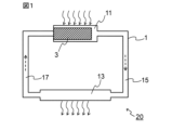
- FIG. 1 is a schematic cross-sectional view of a heat transport device in one embodiment of the present disclosure.
- 1 shows an XRD pattern of the material (TiCO) manufactured in Example 1.
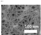
- An FE-SEM image of the material (TiCO) produced in Example 1 is shown.
- wick means a member used for heat transport. More specifically, “wick” refers to a member capable of transporting a working fluid in a liquid state by capillary force.
- the wick includes a material containing nanofibers and/or a two-dimensional substance.
- the term “material” simply means "a material containing nanofibers and/or a two-dimensional substance” (in other words, a material containing at least one of nanofibers and a two-dimensional substance).
- the material containing nanofibers and/or two-dimensional substances typically means a material that is solid and does not contain a binder or the like (for example, a polymer).
- a material containing nanofibers and/or a two-dimensional substance is, in a narrow sense, a material that essentially consists of at least one of nanofibers and a two-dimensional substance (including other objects or impurities that may be unavoidably mixed). good).
- materials including nanofibers and/or two-dimensional substances are not limited thereto.
- the material contained in the wick of this embodiment is a nanofiber (or nanofilament, hereinafter the same) of a predetermined material (substance) and/or a two-dimensional substance.
- the predetermined material that can be used in this embodiment is represented by the following formula (1).
- MQ a O b ...(1) (wherein, M is at least one element selected from the group consisting of groups 3, 4, 5, 6 and 7, and includes so-called early transition metals, such as Sc, Ti, Zr, Hf, V, Nb , Ta, Cr, Mo and Mn, preferably at least one element selected from the group consisting of Ti, V, Cr, Mo and Mn.
- Gain, Q is at least one element selected from the group consisting of Groups 12, 13, 14, 15 and 16 (excluding O), for example consisting of B, C, N, Si, P and S. may contain at least one element selected from the group; a is 0 or more and 2 or less, b is greater than 0 and less than or equal to 2)
- MQO predetermined material
- MQOs include materials represented by the formulas TiO 2 , TiCO, TiCON, VO 2 , VCO, VCON, CrO 2 , CrCO, CrCON, MoO 2 , MoCO, MoCON, MnO 2 , MnCO, MnCON, etc. It will be done.
- the M may be Ti and the Q may be C.
- a may be other than 0.
- the above-mentioned predetermined material may have a peak in the diffraction angle 2 ⁇ in the range of 2° or more and 10° or less in an X-ray diffraction (XRD) pattern.
- XRD X-ray diffraction
- MQO has a crystal structure different from a hexagonal system.
- the crystal structure of MQO can be considered to be anatase type, lepidocrocite type, or a mixture thereof at present.
- the crystal structure of MQO may be lepidocrocite type.
- MQO can be produced using the first raw material and the second raw material, for example, as follows.
- the first raw material contains at least the above M
- the second raw material contains at least the above Q
- the first raw material and the second raw material can react in a protic solvent to generate MQO.
- a material represented by the following formula (2) may be used as the first raw material.
- M c A 1 d ...(2) (In the formula, M is as above, A1 is at least one element selected from the group consisting of Groups 12, 13, 14, 15 and 16, for example selected from the group consisting of B, C, N, O, Si, P and S. may contain at least one element, c and d are each independently from 1 to 5)
- the material represented by formula (2) needs to be different from the MQO of the product.
- the material represented by formula (2) typically does not have a peak in the diffraction angle 2 ⁇ of 2° or more and 10° or less in an X-ray diffraction (XRD) pattern.
- XRD X-ray diffraction
- Examples of the first raw material represented by formula (2) include TiB 2 , TiB, TiC, TiN, TiO 2 , Ti 5 Si 3 , Ti 2 SbP, VO 2 , V 2 O 4 , NbC, Nb 2 O 5 , MoO 2 , MoO 3 , MoS 2 , MnO 2 , Mn 3 O 4 , MnCO 3 and the like.
- a material represented by the following formula (3) may be used as the first raw material.
- M m A 2 X n ...(3) (In the formula, M is as above, X is at least one element selected from the group consisting of C and N, n is 1 or more and 4 or less, m is greater than n and less than or equal to 5, A 2 is at least one element selected from the group consisting of Groups 12, 13, 14, 15 and 16, usually a Group A element, typically Group IIIA and Group IVA, and more details may contain at least one selected from the group consisting of Al, Ga, In, Tl, Si, Ge, Sn, Pb, P, As, S and Cd, preferably Al)
- the MAX phase has a layer composed of two A atoms located between two layers represented by M m X n (which may have a crystal lattice in which each X is located in an octahed
- a 2 atomic layer a layer of A 2 atoms
- the MAX phase is not limited to this.
- Examples of the first raw material represented by formula (3) include Ti 3 AlC 2 , Ti 3 GaC 2 , Ti 3 SiC 2 and the like.
- the material represented by formula (2) and the material represented by formula (3) may be used together (for example, as a mixture).
- An ion-binding substance having a carbon-containing group may be used as the second raw material.
- the ion-binding substance having a carbon-containing group contains C.
- Examples of the ion-binding substance include ammonium salts, phosphates, sulfates, and the like.
- a quaternary ammonium salt may be used as the second raw material.
- quaternary ammonium salts include tetramethylammonium hydroxide (TMAH), tetraethylammonium hydroxide (TEAH), tetrapropylammonium hydroxide (TPAH), tetrabutylammonium hydroxide (TBAH or TBAOH), benzyltrimethylammonium Hydroxide, Tetrabutylammonium Fluoride (TBAF), Tetrabutylammonium Chloride (TBACl), Tetrabutylammonium Bromide (TBAB), Tetrabutylammonium Iodide (TBAI), Benzyltriethylammonium Chloride (BTEAC), Hexadecyltrimethylammonium Bromide , cetyltrimethylammonium bromide (CTAB), benzethonium chloride, benzalkonium chloride, cetylpyridin
- ion-binding substances containing P and/or S may be used as the second raw material.
- the protic solvent may be any solvent as long as it can at least partially dissolve the first raw material and the second raw material, and in particular may be an aqueous solvent.
- aqueous solvent water, alcohol (eg, ethanol, 1-propanol, isopropanol), carboxylic acid (eg, acetic acid, formic acid), etc. are used.
- the aqueous solvent may be composed of water and optionally a liquid substance that is compatible with water (eg, a protic solvent other than water), and is preferably water.
- the first raw material and the second raw material are reacted in a protic solvent.
- the second raw material may be added to the protic solvent in advance.
- the proportion of the second raw material to the total of the protic solvent and the second raw material can be, for example, 5% by mass or more, especially 20% by mass or more, and/or can be, for example, 80% by mass or less, especially 50% by mass or less.
- the first raw material may be further added to the protic solvent to which the second raw material has been added and mixed. In such a mixture, the reaction that produces MQO proceeds.
- the temperature of the mixture (which may contain reaction products) (reaction temperature) may be, for example, 15° C. or higher, especially 40° C. or higher, and/or for example 100° C.
- the mixing time may be, for example, one or more days, especially two or more days, and/or it may be, for example, no more than 10 days, especially no more than 7 days.
- Mixing can be carried out, for example, by rotating and stirring a magnetic stirrer placed in a container while maintaining the reaction temperature with a hot plate stirrer and a hot water bath.
- the treatment operations and conditions that allow the reaction to proceed are not limited to those described above, and may be appropriately selected depending on the first raw material, second raw material, protic solvent, etc. to be used.
- MQO MQO
- the resulting MQO nanofibers can be in the form of nanoribbons extending in nanoscale width.
- a plurality of MQO nanofibers may be bonded and/or integrated with each other to grow into two-dimensionally extending nanoflakes.
- a plurality of MQO nanoflakes may overlap each other (eg, due to van der Waals forces) to form a laminate.
- the generation and growth of such MQO may be considered to be due to a bottom-up synthetic reaction (see, for example, Non-Patent Document 1).
- MQO is solid content.
- MQOs may typically be particles (or powders).
- the mixture after the reaction may be subjected to post-treatment as appropriate.
- post-treatments include, for example, washing, impact application (including application of shear force), drying (for example, freeze drying, heat drying), pulverization, and the like.
- Washing may be performed using a protic solvent. Similar explanations as above may apply for protic solvents, which may be washed with water or alcohol, for example. After washing, separation operations (centrifugation and/or decantation) may be performed. The washing and separation operations can be repeated until the pH of the supernatant after centrifugation becomes, for example, 8 or less.
- cleaning may be performed using an aqueous solution of a metal salt.
- the metal salt can be, for example, a halide (fluoride, chloride, bromide, iodide) of an alkali metal (Li, Na, K, etc.), typically LiCl, NaCl, KCl, etc.
- cleaning may be carried out using, for example, an aqueous metal salt solution having a concentration of 1 to 10 molar.
- separation operations centrifugation and/or decantation
- the washing and separation operations can be repeated as necessary until the pH of the supernatant after centrifugation becomes, for example, 8 or less.
- Shocks such as vibration and/or ultrasound may be applied during and/or after cleaning. This can promote the dispersion of MQO particles (for example, nanofibers/nanoflakes, hereinafter the same). If the MQO particles are aggregated, they can be disintegrated. Such an effect is significantly obtained when impact is applied during cleaning using an aqueous solution of a metal salt (it is thought that the metal cations derived from the metal salt can enter the gaps between the aggregates and disintegrate them). Shock can be applied using, for example, one or more of a handshake, an automatic shaker, a mechanical shaker, a vortex mixer, a homogenizer, an ultrasonic bath, and the like.
- a separation operation can be performed at any appropriate timing to remove unnecessary liquid components if present.
- a drying operation typically freeze-drying or thermal drying, may be carried out. Freeze-drying can be performed, for example, by freezing a mixture containing particles of MQO and a liquid component at any suitable temperature (eg, ⁇ 40° C.) and then drying it under a reduced pressure atmosphere. Thermal drying can be carried out, for example, by drying a mixture containing MQO particles and a liquid component at a temperature of 25° C. or higher (for example, 200° C. or lower) under normal pressure or a reduced pressure atmosphere.
- the pulverization can be carried out using, for example, a mortar and pestle combination, an IKA mill, etc., but is not particularly limited. Grinding may be carried out after drying.
- particles of MQO can be obtained as a material containing MQO.
- MQO particles for example, nanofibers (and in some cases, aggregates of MQO nanofibers, such as MQO nanoflakes, which are also collectively referred to as "MQO nanofibers, etc.") can be obtained.
- MQO is represented by formula (1)
- the material containing MQO does not need to consist only of the constituent elements of formula (1).
- the MQO-containing material may optionally include protons and/or metal cations.
- the MQO-containing material may optionally have a modification or termination T present on its surface selected from the group consisting of hydroxyl groups, chlorine atoms, oxygen atoms, and hydrogen and nitrogen atoms. It may have at least one kind.
- a material containing MQO may have two or more layers between which ammonium ions (e.g., quaternary ammonium cations) and metal cations ( For example, at least one selected from the group consisting of alkali metal ions and alkaline earth metal ions may be present.
- ammonium ions e.g., quaternary ammonium cations
- metal cations For example, at least one selected from the group consisting of alkali metal ions and alkaline earth metal ions may be present.
- Materials containing MQO may contain unreacted first raw materials and/or second raw materials as impurities, and may also contain substances derived from the first raw materials, second raw materials, and/or protic solvents. may include.
- N may exist (remain) in any form in the material containing MQO, such as MQO nanofibers.
- the material containing MQO may include ammonium ions and tetramethylammonium ions.
- the material containing MQO contains a relatively small amount of residual A atoms, for example, 10% by mass or less with respect to the original A atoms. Good too.
- the residual amount of A atoms may be preferably 8% by mass or less, more preferably 6% by mass or less. However, even if the residual amount of A atoms exceeds 10% by mass, there may be no problem depending on the usage conditions.
- Such a supernatant liquid can be made into a slurry containing MQO particles such as MQO nanofibers by directly diluting it with a liquid medium, or by mixing it with a liquid medium after drying.
- the wick of this embodiment can be manufactured by shaping (molding, cutting, etc.) a material containing MQO, such as MQO nanofibers, into a desired shape and size using any appropriate method.
- the wick of this embodiment may be a fibrous structure formed using MQO nanofibers or the like.
- Such fibrous structures can be produced, for example, by applying a slurry containing nanofibers of MQO onto a substrate by any suitable method (e.g., filtration, spraying, bar coating, spin coating, dipping, etc.), drying, and then It can be manufactured by removing the base material.
- the liquid medium contained in the slurry can be selected as appropriate, and includes, for example, protic solvents (the same explanations as above apply), aprotic solvents (such as tetrahydrofuran, methylene chloride, acetonitrile, acetone, N, N- (dimethylformamide, dimethyl sulfoxide, etc.), nonpolar solvents (eg, hexane, benzene, toluene, diethyl ether, chloroform, ethyl acetate), and the like.
- protic solvents such as tetrahydrofuran, methylene chloride, acetonitrile, acetone, N, N- (dimethylformamide, dimethyl sulfoxide, etc.
- nonpolar solvents eg, hexane, benzene, toluene, diethyl ether, chloroform, ethyl acetate
- the wick of this embodiment is obtained.
- the shape and dimensions of the wick of this embodiment can be appropriately selected depending on the desired use.
- a material containing MQO typically has a peak in the diffraction angle 2 ⁇ of 2° or more and 10° or less in an X-ray diffraction (XRD) pattern.
- XRD X-ray diffraction
- a c-axis oriented MQO membrane is installed in the XRD analyzer (for example, as in the example described later, the filter is removed after suction filtration). It is preferable to measure the self-supporting membrane obtained by arranging the surface that was in contact with the filter on the lower side.
- the material of this embodiment (more specifically, MQO) has a Raman shift of at least 275 to 295 cm -1 , 435 to 295 cm -1 in a Raman spectrum using a laser with a wavelength of 514 nm, although this embodiment is not limited to It may have peaks at 455 cm ⁇ 1 and 665 to 745 cm ⁇ 1 .
- the material of this embodiment (more specifically, MQO) has a Raman shift of 140 to 160 cm -1 and 275 to 295 cm in a Raman spectrum using a laser with a wavelength of 514 nm. -1 , 435-455 cm -1 , and 665-745 cm -1 .
- 140 to 160 cm ⁇ 1 is an anatase type peak.
- the material of this embodiment (more specifically, MQO) has a crystal structure of anatase type, lepidocrocite type, or a mixture of these, although the present embodiment is not limited thereto. More preferably, it has a lepidocrocite crystal structure.
- the material of this embodiment (more specifically, MQO) has a Raman shift of at least 275 to 295 cm -1 , 435 to 295 cm -1 in a Raman spectrum using a laser with a wavelength of 514 nm, although this embodiment is not limited to It may have peaks at 455 cm -1 and 665 to 745 cm -1 , and when the intensity of each peak is X, Y, and Z, X is the largest.
- the material of this embodiment (more specifically, MQO) has a Raman shift of at least 180 to 200 cm ⁇ 1 in a Raman spectrum using a laser with a wavelength of 514 nm,
- a Raman shift of at least 180 to 200 cm ⁇ 1 in a Raman spectrum using a laser with a wavelength of 514 nm When there are peaks at the positions of 275 to 295 cm -1 , 375 to 395 cm -1 , 435 to 455 cm -1 , and 665 to 745 cm -1 and the intensities of each peak are V, X, Y, Z, and W. It may take the form that X is the largest.
- the Raman spectrum is measured with a Raman spectrometer using a laser beam with a wavelength of 514 nm as an excitation light source (the vertical axis is intensity and the horizontal axis is Raman shift). Peaks in a Raman spectrum can be identified visually or using software used with a Raman spectrometer.
- the particle size of the particles of MQO can be, for example, 0.01 nm or more, especially 0.1 nm or more, even 1 nm or more, and/or can be, for example, less than 1000 nm, especially 100 nm or less, and even 50 nm or less. Such particles may also be referred to as nanoparticles.
- the particle morphology of MQO is nanofibers and/or two-dimensional materials.
- the two-dimensional material includes one or more of nanoflakes and laminates of nanoflakes. In this embodiment, the two-dimensional material is not limited to only nanoflakes and a laminate of nanoflakes.
- a material comprising MQO typically particles (e.g. nanofibers/nanoflakes) of MQO, e.g. nanofibers of MQO (and optionally aggregates of nanofibers of MQO, e.g. nanoflakes of MQO) ) is provided.
- MQO nanofibers have a hydrophilic surface and have nano-order cross-sectional dimensions.
- a wick containing such MQO nanofibers has a large ability to attract (e.g., suck up) a working fluid in a liquid state by capillary action, and therefore can transfer (e.g., suck up) a working fluid in a liquid state at a high speed. .
- the reason for this is that due to the nano-order cross-sectional dimensions, the volume density of the nanofibers in the wick is high, and the gaps between the nanofibers form a narrow space (flow path for the working fluid).
- the total surface area of the nanofibers obtained is large, and the hydrophilic surface makes it easier for a working fluid in a liquid state (typically, but not limited to, water) to wet and spread on the surface of the MQO nanofibers. This may be possible.
- nanofiber of MQO is a solid substance extending in the longitudinal direction, and the external dimensions of a cross section perpendicular to the longitudinal direction (cross-sectional external dimensions) are nano-order (i.e., 1 nm or more and 1000 nm or more). (less than 1 nm) or smaller than that (less than 1 nm, for example, 0.1 nm or more and less than 1 nm).
- the length of the MQO nanofibers in the longitudinal direction is not particularly limited. That is, the length of the nanofiber in the longitudinal direction is not limited to nano-order (ie, 1 nm or more and less than 1000 nm), but may be micron-order (1 ⁇ m or more and less than 1000 ⁇ m).
- the cross-sectional dimensions of the nanofibers can be, for example, 0.1 nm or more, especially 1 nm or more, and for example 100 nm or less, especially 50 nm or less, preferably 15 nm or less.
- a wick including MQO nanofibers or the like having such a small cross-sectional dimension can transport a working fluid in a liquid state at a higher velocity.
- MQO nanofibers having such small cross-sectional dimensions can be realized.
- the cross-sectional external dimensions of the MQO nanofibers mean the shortest distance passing through the center in a cross section that traverses the longitudinal direction of the MQO nanofibers.
- the shape of the cross section of the MQO nanofiber is not particularly limited, but may be approximated by, for example, a rectangle (rectangle, square, etc.) or an ellipse (oblate circle, perfect circle, etc.).
- the MQO nanofiber is in the form of a nanoribbon
- its cross-sectional shape can be approximated by a rectangle
- the cross-sectional external dimension can correspond to the short side length of the rectangle.
- the MQO nanofiber is in the form of a nanofilament
- its cross-sectional shape can be approximated by a flat circle
- the cross-sectional external dimensions can correspond to the short axis length of the flat circle.
- the BET specific surface area of a material containing MQO such as MQO nanofibers is not particularly limited, but may be, for example, 10 m 2 /g or more and 500 m 2 /g or less.
- BET specific surface area is the isothermal adsorption curve of nitrogen gas or other gases mentioned above under liquid nitrogen temperature (77 K) by an adsorption method using nitrogen gas or other suitable gas (e.g. krypton (Kr) gas, etc.). It is calculated using the BET formula.
- a "two-dimensional substance” has a two-dimensionally extending surface (also referred to as a plane or two-dimensional sheet surface), and the maximum dimension of the surface (which may correspond to the "in-plane dimension" of a particle) ), the thickness of which is nano-order (i.e., 1 nm or more and less than 1000 nm) or smaller sub-nano order (less than 1 nm, e.g. 0.1 nm or more and less than 1 nm). mean something
- the in-plane dimension is not limited to nano-order (ie, 1 nm or more and less than 1000 nm), but may be micron-order (1 ⁇ m or more and less than 1000 ⁇ m).
- the two-dimensional material includes one or more of nanoflakes and nanoflake stacks, as described above. Nanoflakes may also be referred to as nanosheets or two-dimensional (nano)sheets.
- the thickness of one layer of nanoflakes can be, for example, 0.01 nm or more, especially 0.8 nm or more, and eg 20 nm or less, especially 3 nm or less.
- the in-plane dimensions of the nanoflakes may be, for example, 0.1 ⁇ m or more, especially 1 ⁇ m or more, and for example 200 ⁇ m or less, especially 40 ⁇ m or less. Nanoflakes can be constructed by aggregating nanofibers.
- a stack of nanoflakes may also be referred to as a multilayer MQO.
- the distance (interlayer distance or void size) between two adjacent nanoflakes (or two adjacent layers of MQO) is not particularly limited.
- the above-mentioned dimensions are calculated using a scanning electron microscope (SEM), a transmission electron microscope (TEM), or an atomic force microscope (processed by a method such as a focused ion beam (FIB), if necessary).
- SEM scanning electron microscope
- TEM transmission electron microscope
- FIB focused ion beam
- real space calculated from the number average dimension (number average of at least 40) based on photographs observed with AFM) or the position on the reciprocal lattice space of the (002) plane measured by X-ray diffraction (XRD) method. It can be determined as a distance.
- XRD X-ray diffraction
- the cross-sectional external dimensions of MQO nanofibers are determined by exposing the cross-section of a wick containing MQO nanofibers using a method such as a focused ion beam (FIB), and then using a scanning electron microscope (SEM) or a transmission electron microscope (SEM) to examine the exposed cross-section. Take an image using a TEM, extract at least 40 MQO nanofibers in which a cross section crossing the longitudinal direction appears, and calculate the number average of their cross-sectional external dimensions. is required.
- FIB focused ion beam
- SEM scanning electron microscope
- SEM transmission electron microscope
- MQO is not limited to the above forms, but may have any suitable form.
- a heat transport device refers to a device that transports heat using a phase change of a working fluid.
- Phase change of the working fluid refers to evaporation and condensation.
- the heat transport device 20 of the present embodiment includes: A housing 1 having a space inside; A wick 3 disposed within the housing 1; A working fluid (not shown) sealed in the housing 1 in a state where it can come into contact with the wick 3; including.
- a working fluid (not shown) sealed in the housing 1 in a state where it can come into contact with the wick 3; including.
- the wick 3 the one described above in the first embodiment is used.
- FIG. 1 exemplarily shows a case where the heat transport device 20 is a loop-type heat pipe.
- the housing 1 includes an evaporator 11, a condenser 13, and a gas flow path 15 and a liquid flow path 17 that connect these, respectively.
- the passage 15 and the liquid flow passage 17 integrally constitute the internal space of the housing 1 .
- the wick 3 is placed within the evaporator 11.
- a working fluid (not shown) is sealed in the internal space of the housing 1 .
- the housing 1 is made of a thermally conductive material (for example, metal) at least in the evaporator 11 and the condenser 13.
- the working fluid is evaporated in the evaporator 11 (relatively high temperature part) to which heat is supplied from the outside (heat source), and the working fluid in a gaseous state moves in the gas flow path 15,
- the condenser 13 a relatively low-temperature part
- heat is released to the outside, and the working fluid, which has become a liquid, passes through the liquid flow path 17 to the evaporator 11 due to the capillary force of the wick 3. be transported (returned).
- the working fluid circulates within the housing 1 while changing its phase.
- the flow of the working fluid is schematically shown by dotted line arrows
- the supply of heat from the outside (heat input) and the radiation of heat to the outside (thermal output) are schematically shown by dotted line arrows.
- the working fluid in the liquid state can be transported at a high speed, and high heat transport performance can be obtained. , the maximum heat transport amount of the heat transport device 20 is improved.
- FIG. 1 shows a case where the heat transport device 20 is a loop-type heat pipe, but the heat transport device of this embodiment uses no wick except for using the wick 3 described above in Embodiment 1.
- the structure of a known heat transport device for example, a tubular heat pipe, a vapor chamber, etc. may be applied.
- the wick and the heat transport device in an embodiment of the present disclosure have been described above in detail, the present disclosure can be modified in various ways. Note that the wick of the present disclosure may be manufactured by a method different from the manufacturing method in the embodiments described above.
- Example 1 relates to the wick of Embodiment 1, which uses TiCO nanofibers.
- ⁇ Preparation of slurry containing TiCO nanofibers First, in a container (100 mL Eyeboy), 1 g of titanium diboride (TiB 2 , manufactured by Alfa Aesar) and 30 mL of a 25% by mass tetramethylammonium hydroxide (TMAH) aqueous solution (Tokyo (manufactured by Kasei Kogyo Co., Ltd.). A stirrer tip with a length approximately the same size (35 mm) as the inner diameter of the circular bottom of the container was placed there. While keeping the container at 50° C. in a water bath, the mixture in the container was stirred with a stirrer tip and maintained for 120 hours, thereby allowing the reaction to proceed.
- TMAH tetramethylammonium hydroxide
- the reaction mixture in the container was then transferred to a 50 mL centrifuge tube with a stainless steel spatula (without adding any liquid medium such as ethanol or water). Centrifugation was performed using a centrifuge at 3500 G for 5 minutes to sediment the solid content. (i) After centrifugation, discard the supernatant, (ii) add 40 mL of ethanol (manufactured by Fujifilm Wako Pure Chemical Industries, Ltd.) to the remaining sediment in the centrifuge tube, and handshake for 5 minutes (reslurry). (iii) Centrifugation was performed under the same conditions as above. These operations (i) to (iii) were repeated until the pH of the supernatant liquid became 8 or less.
- the pH of the supernatant liquid became 8 or less, so the supernatant liquid was discarded and the repeating operation was completed.
- 40 mL of pure water was added to the remaining sediment in the centrifuge tube, and the mixture was shaken and stirred for 15 minutes using an automatic shaker. Thereafter, centrifugation was performed using a centrifuge at 3500 G for 30 minutes, and the supernatant was collected as a sample slurry.
- the sample slurry obtained corresponds to a slurry containing TiCO nanofibers (see analysis results below).
- the wick sample prepared above was placed in a petri dish filled with water with the WT surface (1 cm x 100 ⁇ m) vertically placed on the top and bottom surfaces, and placed at a depth of about 1 mm. When it was soaked in water, water was sucked up to the top surface at a speed of 4 mm/s. From this result, the volume of water sucked up by the wick sample per unit area per unit time is 4 ⁇ 10 -3 m 3 /(m 2 s), and therefore the mass of water sucked up per unit area per unit time is , 4 kg/(m 2 ⁇ s) (specific gravity of water: 1000 kg/m 3 ). Since the heat of evaporation of water per unit mass at 25° C.
- the amount of heat that this wick sample can take away by evaporating water at 25° C. is calculated to be 9768 kW/m 2 . That is, in the wick sample of Example 1, the water transport speed was 4 mm/s, and the water heat transport performance at 25° C. was about 10 4 kW/m 2 .
- FIG. 3 shows an FE-SEM image. As can be seen from Figure 3, this material had a cross-sectional profile of approximately 5 nm.
- Comparative Example 1 relates to a wick using particles of MXene, which is a type of two-dimensional material.
- MAX particles precursor of MXene particles
- TiC powder, Ti powder, and Al powder all manufactured by Kojundo Kagaku Kenkyusho Co., Ltd.
- Al powder all manufactured by Kojundo Kagaku Kenkyusho Co., Ltd.
- the mixture was added and mixed for 24 hours.
- the obtained mixed powder was fired at 1350° C. for 2 hours in an Ar atmosphere.
- the fired body (block) thus obtained was ground with an end mill to a maximum size of 40 ⁇ m or less.
- Ti 3 AlC 2 particles were obtained as MAX particles.
- etching was performed under the following etching conditions to obtain a solid-liquid mixture (slurry) containing a solid component derived from the Ti 3 AlC 2 powder.
- Etching conditions ⁇ Precursor: Ti 3 AlC 2 (passed through a 45 ⁇ m sieve) ⁇ Etching solution composition: 49%HF 6mL 18 mL H2O HCl (12M) 36mL ⁇ Precursor input amount: 3.0g ⁇ Etching container: 100mL Eye Boy ⁇ Etching temperature: 35°C ⁇ Etching time: 24h ⁇ Stirrer rotation speed: 400 rpm
- the slurry was divided into two parts, inserted into two 50 mL centrifuge tubes, centrifuged at 3500 G using a centrifuge, and then the supernatant liquid was discarded.
- the operation of adding 40 mL of pure water to the remaining precipitate in each centrifuge tube, performing centrifugation again at 3500 G, and separating and removing the supernatant liquid was repeated 11 times. After the final centrifugation, the supernatant was discarded and the Ti 3 C 2 T x -water medium clay was obtained.
- this supernatant liquid was centrifuged using a centrifuge at 4300G for 2 hours, the supernatant liquid was discarded, and a single-layer/poor-layer MXene-containing clay was prepared as a mono-layer/poor-layer MXene-containing sample. I got it.
- the wick sample prepared above was placed in a petri dish filled with water with the WT surface (1 cm x 100 ⁇ m) vertically placed on the top and bottom surfaces, and placed at a depth of about 1 mm. When it was soaked in water, it was unable to absorb water at all (the suction height was 0 mm).
- Comparative Example 2 relates to a wick using a sintered body (porous metal sintered body) of metal powder (copper powder).
- wick Copper powder with an average particle size D50 of 50 ⁇ m was used as the metal powder, and acrylic resin (binder) and copper powder were mixed at a volume ratio of 1:1.
- the resulting mixture was heat treated at 400° C. for 1 hour to burn off the acrylic resin and obtain a porous metal sintered body.
- the obtained porous metal sintered body was cut to obtain a wick sample having a width (W) of 1 cm, a length (L) of 2 cm, and a thickness (T) of 100 ⁇ m.
- wick sample prepared above was placed in a petri dish filled with water with the WT surface (1 cm x 100 ⁇ m) vertically placed on the top and bottom surfaces, and placed at a depth of about 1 mm. When it was soaked in water, water was sucked up to the top surface at a speed of 0.5 mm/s. From this result, the wick sample of Comparative Example 2 has a water transfer rate of 0.5 mm/s, and according to the same calculation as Example 1, the water heat transfer performance at 25°C is approximately 10 3 kW/m. It was 2 .
- Comparative Example 3 relates to a wick using a sintered body (porous metal sintered body) of metal powder (titanium powder).
- the wick of the present disclosure can be used in a heat transport device that utilizes phase change of a working fluid to transport the working fluid by capillary force.
- the heat transport device of the present disclosure can be incorporated into an electronic device and used to release (remove) heat from a heat source of the electronic device.
- the wick and heat transport device of the present disclosure can be used not only in these applications but also in any suitable application.
- a wick used for heat transport The formula below: MQ a O b (wherein M is at least one element selected from the group consisting of Groups 3, 4, 5, 6, and 7; Q is at least one element selected from the group consisting of Groups 12, 13, 14, 15 and 16 (excluding O), a is 0 or more and 2 or less, b is greater than 0 and less than or equal to 2)
- a heat transport device that utilizes phase change of a working fluid A housing having a space inside; The wick according to any one of ⁇ 1> to ⁇ 3>, disposed within the housing; a working fluid sealed within the housing so as to be in contact with the wick; heat transport equipment, including
Landscapes
- Engineering & Computer Science (AREA)
- Life Sciences & Earth Sciences (AREA)
- Sustainable Development (AREA)
- Physics & Mathematics (AREA)
- Thermal Sciences (AREA)
- Mechanical Engineering (AREA)
- General Engineering & Computer Science (AREA)
- Chemical & Material Sciences (AREA)
- Chemical Kinetics & Catalysis (AREA)
- General Chemical & Material Sciences (AREA)
- Textile Engineering (AREA)
- Physical Or Chemical Processes And Apparatus (AREA)
Abstract
Provided is a wick used to transport heat, the wick containing materials including nanofibers and/or a two-dimensional substance of a material represented by the formula MQaOb (wherein M is at least one element selected from the group consisting of Groups 3, 4, 5, 6, and 7, Q is at least one element (excluding O) selected from the group consisting of Groups 12, 13, 14, 15, and 16, a is 0 or more and 2 or less, and b is greater than 0 and 2 or less).
Description
本開示は、ウィックおよび熱輸送装置に関し、より詳細には、熱輸送のために使用されるウィック、および作動流体の相変化を利用した熱輸送装置に関する。
The present disclosure relates to a wick and a heat transport device, and more particularly to a wick used for heat transport and a heat transport device that utilizes a phase change of a working fluid.
従来、ヒートパイプやベーパーチャンバー等の、作動流体の相変化(より詳細には、蒸発および凝縮)を利用した熱輸送装置が知られている。かかる熱輸送装置においては、液体状態の作動流体を毛細管力(毛細管現象による吸引力)により移送するウィックが使用されている。
Conventionally, heat transport devices such as heat pipes and vapor chambers that utilize phase change (more specifically, evaporation and condensation) of a working fluid are known. Such a heat transport device uses a wick that transports a working fluid in a liquid state by capillary force (suction force due to capillary action).
例えば、特許文献1には、平均粒径が20μm以上200μm以下の金属粒子の焼結体をウィックとして用いることが記載されている。また例えば、特許文献2には、炭素繊維および/または酸化繊維を含む繊維構造体の少なくとも一部に炭素質多孔体が充填された繊維含有多孔体であって、炭素質多孔体の細孔径分布において細孔径10μm以下の領域に少なくとも1つのピークを有する繊維含有多孔体をウィックとして用いることが記載されている。
For example, Patent Document 1 describes that a sintered body of metal particles having an average particle diameter of 20 μm or more and 200 μm or less is used as a wick. For example, Patent Document 2 discloses a fiber-containing porous body in which at least a portion of a fibrous structure containing carbon fibers and/or oxidized fibers is filled with a carbonaceous porous body, the pore size distribution of the carbonaceous porous body being describes the use of a fiber-containing porous material having at least one peak in a region with a pore diameter of 10 μm or less as a wick.
上述したような熱輸送装置は、熱伝導性を少なくとも部分的に有する筐体を用い、筐体内にウィックが配置されるとともに作動流体が封入された構成を有する。筐体内では、外部から熱が供給される比較的高温の部分において作動流体が蒸発し、気体状態になった作動流体は筐体内を移動し、比較的低温の部分において凝縮することで熱を外部へ放出し、液体状態になった作動流体は比較的高温の部分へとウィックの毛細管力により移送される(戻される)。
The heat transport device as described above uses a casing that at least partially has thermal conductivity, and has a configuration in which a wick is disposed within the casing and a working fluid is sealed therein. Inside the housing, the working fluid evaporates in relatively high-temperature areas where heat is supplied from the outside, and the working fluid in a gaseous state moves inside the housing and condenses in relatively low-temperature areas, transferring heat to the outside. The working fluid in a liquid state is transferred (returned) to a relatively high temperature area by the capillary force of the wick.
近年、熱輸送装置が組み込まれ得る電子機器の小型化等により、熱輸送装置には熱輸送性能の一層の向上が求められている。従来一般的に、気体状態の作動流体が筐体内を移動する速度より、液体状態の作動流体がウィックの毛細管力により移送される速度のほうが小さく、熱輸送装置の熱輸送性能は、液体状態の作動流体がウィックの毛細管力により移送される速度により制限され得る。熱輸送装置の熱輸送性能を向上させるためには、ウィックにおける液体状態の作動流体の移送速度は、より大きいほうが望ましい。
In recent years, due to the miniaturization of electronic devices into which heat transport devices can be incorporated, further improvements in heat transport performance have been required of heat transport devices. Conventionally, the speed at which a working fluid in a liquid state is transferred by the capillary force of a wick is generally smaller than the speed at which a working fluid in a gaseous state moves within a housing, and the heat transport performance of a heat transport device is The speed at which the working fluid is transported by capillary forces in the wick may be limited. In order to improve the heat transport performance of the heat transport device, it is desirable that the transfer speed of the liquid working fluid in the wick be higher.
本開示の目的は、液体状態の作動流体の移送速度が大きい、新規なウィックを提供することにある。本開示の更なる目的は、かかるウィックを用いた新規な熱輸送装置を提供することにある。
An object of the present disclosure is to provide a novel wick that has a high transfer rate of working fluid in a liquid state. A further object of the present disclosure is to provide a novel heat transport device using such a wick.
本開示の1つの要旨によれば、熱輸送のために使用されるウィックであって、
以下の式:
MQaOb
(式中、Mは、第3、4、5、6および7族からなる群より選択される少なくとも1種の元素であり、
Qは、第12、13、14、15および16族からなる群より選択される少なくとも1種の元素(但し、Oを除く)であり、
aは、0以上2以下であり、
bは、0より大きく、2以下である)
で表されるナノファイバーおよび/または2次元物質を含む材料
を含む、ウィックが提供される。 According to one aspect of the present disclosure, a wick used for heat transport, comprising:
The formula below:
MQ a O b
(wherein M is at least one element selected from the group consisting of Groups 3, 4, 5, 6, and 7;
Q is at least one element selected from the group consisting of Groups 12, 13, 14, 15 and 16 (excluding O),
a is 0 or more and 2 or less,
b is greater than 0 and less than or equal to 2)
A wick is provided that includes a material including nanofibers and/or two-dimensional materials represented by
以下の式:
MQaOb
(式中、Mは、第3、4、5、6および7族からなる群より選択される少なくとも1種の元素であり、
Qは、第12、13、14、15および16族からなる群より選択される少なくとも1種の元素(但し、Oを除く)であり、
aは、0以上2以下であり、
bは、0より大きく、2以下である)
で表されるナノファイバーおよび/または2次元物質を含む材料
を含む、ウィックが提供される。 According to one aspect of the present disclosure, a wick used for heat transport, comprising:
The formula below:
MQ a O b
(wherein M is at least one element selected from the group consisting of
Q is at least one element selected from the group consisting of
a is 0 or more and 2 or less,
b is greater than 0 and less than or equal to 2)
A wick is provided that includes a material including nanofibers and/or two-dimensional materials represented by
本開示のもう1つの要旨によれば、作動流体の相変化を利用した熱輸送装置であって、
内部に空間を有する筐体と、
前記筐体内に配置された、前記ウィックと、
前記ウィックと接触可能な状態で、前記筐体内に封入された作動流体と、
を含む、熱輸送装置が提供される。 According to another gist of the present disclosure, there is provided a heat transport device using phase change of a working fluid, comprising:
A housing having a space inside;
the wick disposed within the housing;
a working fluid sealed within the housing so as to be in contact with the wick;
A heat transport device is provided.
本開示によれば、液体状態の作動流体の移送速度が大きい、新規なウィックが提供される。更に、本開示によれば、かかるウィックを用いた新規な熱輸送装置が提供される。
According to the present disclosure, a novel wick is provided that has a high transfer rate of working fluid in a liquid state. Furthermore, according to the present disclosure, a novel heat transport device using such a wick is provided.
以下、本開示の実施形態におけるウィックおよび熱輸送装置について詳述するが、本開示はこれら実施形態に限定されるものではない。
Hereinafter, the wick and the heat transport device in the embodiments of the present disclosure will be described in detail, but the present disclosure is not limited to these embodiments.
(実施形態1:ウィック)
本実施形態は、ウィックに関する。本開示において、「ウィック」は、熱輸送のために使用される部材を意味する。より詳細には、「ウィック」は、液体状態の作動流体を毛細管力により移送可能な部材を意味する。 (Embodiment 1: Wick)
This embodiment relates to a wick. In this disclosure, "wick" means a member used for heat transport. More specifically, "wick" refers to a member capable of transporting a working fluid in a liquid state by capillary force.
本実施形態において、ウィックは、ナノファイバーおよび/または2次元物質を含む材料、を含む。本開示において、単に「材料」という場合、「ナノファイバーおよび/または2次元物質を含む材料」(換言すれば、ナノファイバーおよび2次元物質の少なくともいずれかを含む材料)を意味するものとする。本実施形態において、ナノファイバーおよび/または2次元物質を含む材料は、代表的には、固形分であり、かつ、バインダー等(例えばポリマー)を含まない材料を意味する。ナノファイバーおよび/または2次元物質を含む材料は、狭義には、ナノファイバーおよび2次元物質の少なくともいずれかから実質的に成る材料(不可避的に混入し得る他の物体や不純物等を含んでいてよい)を意味し得る。しかしながら、ナノファイバーおよび/または2次元物質を含む材料は、これらに限定されない。
In this embodiment, the wick includes a material containing nanofibers and/or a two-dimensional substance. In the present disclosure, the term "material" simply means "a material containing nanofibers and/or a two-dimensional substance" (in other words, a material containing at least one of nanofibers and a two-dimensional substance). In this embodiment, the material containing nanofibers and/or two-dimensional substances typically means a material that is solid and does not contain a binder or the like (for example, a polymer). A material containing nanofibers and/or a two-dimensional substance is, in a narrow sense, a material that essentially consists of at least one of nanofibers and a two-dimensional substance (including other objects or impurities that may be unavoidably mixed). good). However, materials including nanofibers and/or two-dimensional substances are not limited thereto.
本実施形態のウィックに含まれる材料は、所定の材料(物質)のナノファイバー(またはナノフィラメント、以下も同様)および/または2次元物質である。本実施形態において使用可能な所定の材料は、以下の式(1)で表されるものである。
MQaOb ・・・(1)
(式中、Mは、第3、4、5、6および7族からなる群より選択される少なくとも1種の元素であり、いわゆる早期遷移金属、例えばSc、Ti、Zr、Hf、V、Nb、Ta、Cr、MoおよびMnからなる群より選択される少なくとも1種の元素を含み得、好ましくは、Ti、V、Cr、MoおよびMnからなる群より選択される少なくとも1種の元素を含み得、
Qは、第12、13、14、15および16族からなる群より選択される少なくとも1種の元素(但し、Oを除く)であり、例えばB、C、N、Si、PおよびSからなる群より選択される少なくとも1種の元素を含み得、
aは、0以上2以下であり、
bは、0より大きく、2以下である) The material contained in the wick of this embodiment is a nanofiber (or nanofilament, hereinafter the same) of a predetermined material (substance) and/or a two-dimensional substance. The predetermined material that can be used in this embodiment is represented by the following formula (1).
MQ a O b ...(1)
(wherein, M is at least one element selected from the group consisting of groups 3, 4, 5, 6 and 7, and includes so-called early transition metals, such as Sc, Ti, Zr, Hf, V, Nb , Ta, Cr, Mo and Mn, preferably at least one element selected from the group consisting of Ti, V, Cr, Mo and Mn. Gain,
Q is at least one element selected from the group consisting of Groups 12, 13, 14, 15 and 16 (excluding O), for example consisting of B, C, N, Si, P and S. may contain at least one element selected from the group;
a is 0 or more and 2 or less,
b is greater than 0 and less than or equal to 2)
MQaOb ・・・(1)
(式中、Mは、第3、4、5、6および7族からなる群より選択される少なくとも1種の元素であり、いわゆる早期遷移金属、例えばSc、Ti、Zr、Hf、V、Nb、Ta、Cr、MoおよびMnからなる群より選択される少なくとも1種の元素を含み得、好ましくは、Ti、V、Cr、MoおよびMnからなる群より選択される少なくとも1種の元素を含み得、
Qは、第12、13、14、15および16族からなる群より選択される少なくとも1種の元素(但し、Oを除く)であり、例えばB、C、N、Si、PおよびSからなる群より選択される少なくとも1種の元素を含み得、
aは、0以上2以下であり、
bは、0より大きく、2以下である) The material contained in the wick of this embodiment is a nanofiber (or nanofilament, hereinafter the same) of a predetermined material (substance) and/or a two-dimensional substance. The predetermined material that can be used in this embodiment is represented by the following formula (1).
MQ a O b ...(1)
(wherein, M is at least one element selected from the group consisting of
Q is at least one element selected from the group consisting of
a is 0 or more and 2 or less,
b is greater than 0 and less than or equal to 2)
上記所定の材料を、以下、単に「MQO」とも称する。MQOの例としては、TiO2、TiCO、TiCON、VO2、VCO、VCON、CrO2、CrCO、CrCON、MoO2、MoCO、MoCON、MnO2、MnCO、MnCONなどの式で表される材料が含まれる。例えば、式(1)において、前記MがTiであり、前記QがCであってよい。また例えば、式(1)において、前記aが0でないものであってよい。
The above-mentioned predetermined material is also simply referred to as "MQO" hereinafter. Examples of MQOs include materials represented by the formulas TiO 2 , TiCO, TiCON, VO 2 , VCO, VCON, CrO 2 , CrCO, CrCON, MoO 2 , MoCO, MoCON, MnO 2 , MnCO, MnCON, etc. It will be done. For example, in formula (1), the M may be Ti and the Q may be C. Further, for example, in formula (1), a may be other than 0.
上記所定の材料は、代表的には、X線回折(XRD)パターンにおいて回折角2θが2°以上10°以下の範囲にピークを有し得る。
Typically, the above-mentioned predetermined material may have a peak in the diffraction angle 2θ in the range of 2° or more and 10° or less in an X-ray diffraction (XRD) pattern.
MQOは、六方晶系とは異なる結晶構造を有する。本実施形態はいかなる理論によっても拘束されないが、MQOの結晶構造は、現時点では、アナターゼ型またはレピドクロサイト型あるいはこれらが混在したものであると考えられ得る。例えば、MQOの結晶構造は、レピドクロサイト型であってよい。
MQO has a crystal structure different from a hexagonal system. Although this embodiment is not bound by any theory, the crystal structure of MQO can be considered to be anatase type, lepidocrocite type, or a mixture thereof at present. For example, the crystal structure of MQO may be lepidocrocite type.
MQOは、例えば次のようにして、第1原料および第2原料を用いて製造可能である。第1原料は、少なくとも上記Mを含有し、第2原料は、少なくとも上記Qを含有し、第1原料および第2原料は、プロトン性溶媒中で反応してMQOを生成させ得るものである。
MQO can be produced using the first raw material and the second raw material, for example, as follows. The first raw material contains at least the above M, the second raw material contains at least the above Q, and the first raw material and the second raw material can react in a protic solvent to generate MQO.
第1原料として、以下の式(2)で表される材料が使用され得る。
McA1 d ・・・(2)
(式中、Mは、上記の通りであり、
A1は、第12、13、14、15および16族からなる群より選択される少なくとも1種の元素であり、例えばB、C、N、O、Si、PおよびSからなる群より選択される少なくとも1種の元素を含み得、
cおよびdは、それぞれ互いに独立して、1以上5以下である)
但し、式(2)で表される材料は、生成物のMQOと相違することを要する。式(2)で表される材料は、代表的には、X線回折(XRD)パターンにおいて回折角2θが2°以上10°以下の範囲にピークを有しないものであり得る。 As the first raw material, a material represented by the following formula (2) may be used.
M c A 1 d ...(2)
(In the formula, M is as above,
A1 is at least one element selected from the group consisting of Groups 12, 13, 14, 15 and 16, for example selected from the group consisting of B, C, N, O, Si, P and S. may contain at least one element,
c and d are each independently from 1 to 5)
However, the material represented by formula (2) needs to be different from the MQO of the product. The material represented by formula (2) typically does not have a peak in the diffraction angle 2θ of 2° or more and 10° or less in an X-ray diffraction (XRD) pattern.
McA1 d ・・・(2)
(式中、Mは、上記の通りであり、
A1は、第12、13、14、15および16族からなる群より選択される少なくとも1種の元素であり、例えばB、C、N、O、Si、PおよびSからなる群より選択される少なくとも1種の元素を含み得、
cおよびdは、それぞれ互いに独立して、1以上5以下である)
但し、式(2)で表される材料は、生成物のMQOと相違することを要する。式(2)で表される材料は、代表的には、X線回折(XRD)パターンにおいて回折角2θが2°以上10°以下の範囲にピークを有しないものであり得る。 As the first raw material, a material represented by the following formula (2) may be used.
M c A 1 d ...(2)
(In the formula, M is as above,
A1 is at least one element selected from the group consisting of
c and d are each independently from 1 to 5)
However, the material represented by formula (2) needs to be different from the MQO of the product. The material represented by formula (2) typically does not have a peak in the diffraction angle 2θ of 2° or more and 10° or less in an X-ray diffraction (XRD) pattern.
式(2)で表される第1原料の例には、TiB2、TiB、TiC、TiN、TiO2、Ti5Si3、Ti2SbP、VO2、V2O4、NbC、Nb2O5、MoO2、MoO3、MoS2、MnO2、Mn3O4、MnCO3などが含まれる。第1原料として使用可能なMnO2は、XRDパターンにおいて、2θ=13°付近にピークを有し、2θが2°以上10°以下の範囲にピークを有しない。
Examples of the first raw material represented by formula (2) include TiB 2 , TiB, TiC, TiN, TiO 2 , Ti 5 Si 3 , Ti 2 SbP, VO 2 , V 2 O 4 , NbC, Nb 2 O 5 , MoO 2 , MoO 3 , MoS 2 , MnO 2 , Mn 3 O 4 , MnCO 3 and the like. MnO 2 that can be used as the first raw material has a peak in the vicinity of 2θ=13° in the XRD pattern, and does not have a peak in the range where 2θ is 2° or more and 10° or less.
あるいは、または上記に加えて、第1原料として、以下の式(3)で表される材料(以下、単に「MAX相」または「MAX原料」とも言う)が使用され得る。
MmA2Xn ・・・(3)
(式中、Mは、上記の通りであり、
Xは、CおよびNからなる群より選択される少なくとも1種の元素であり、
nは、1以上4以下であり、
mは、nより大きく、5以下であり、
A2は、第12、13、14、15および16族からなる群より選択される少なくとも1種の元素であり、通常はA族元素、代表的にはIIIA族およびIVA族であり、より詳細にはAl、Ga、In、Tl、Si、Ge、Sn、Pb、P、As、SおよびCdからなる群より選択される少なくとも1種を含み得、好ましくはAlである)
MAX相は、MmXnで表される2つの層(各XがMの八面体アレイ内に位置する結晶格子を有し得る)の間に、A2原子により構成される層が位置した結晶構造を有する。MAX相は、代表的にm=n+1の場合、n+1層のM原子の層の各間にX原子の層が1層ずつ配置され(これらを合わせて「MmXn層」とも称する)、n+1番目のM原子の層の次の層としてA2原子の層(「A2原子層」)が配置された繰り返し単位を有する。しかしながら、MAX相はこれに限定されない。 Alternatively, or in addition to the above, a material represented by the following formula (3) (hereinafter also simply referred to as "MAX phase" or "MAX raw material") may be used as the first raw material.
M m A 2 X n ...(3)
(In the formula, M is as above,
X is at least one element selected from the group consisting of C and N,
n is 1 or more and 4 or less,
m is greater than n and less than or equal to 5,
A 2 is at least one element selected from the group consisting of Groups 12, 13, 14, 15 and 16, usually a Group A element, typically Group IIIA and Group IVA, and more details may contain at least one selected from the group consisting of Al, Ga, In, Tl, Si, Ge, Sn, Pb, P, As, S and Cd, preferably Al)
The MAX phase has a layer composed of two A atoms located between two layers represented by M m X n (which may have a crystal lattice in which each X is located in an octahedral array of It has a crystal structure. Typically, in the MAX phase, when m=n+1, one layer of X atoms is arranged between each of the n+1 layers of M atoms (these are also collectively referred to as "M m X n layers"), It has a repeating unit in which a layer of A 2 atoms (“A 2 atomic layer”) is arranged as the next layer of the n+1-th layer of M atoms. However, the MAX phase is not limited to this.
MmA2Xn ・・・(3)
(式中、Mは、上記の通りであり、
Xは、CおよびNからなる群より選択される少なくとも1種の元素であり、
nは、1以上4以下であり、
mは、nより大きく、5以下であり、
A2は、第12、13、14、15および16族からなる群より選択される少なくとも1種の元素であり、通常はA族元素、代表的にはIIIA族およびIVA族であり、より詳細にはAl、Ga、In、Tl、Si、Ge、Sn、Pb、P、As、SおよびCdからなる群より選択される少なくとも1種を含み得、好ましくはAlである)
MAX相は、MmXnで表される2つの層(各XがMの八面体アレイ内に位置する結晶格子を有し得る)の間に、A2原子により構成される層が位置した結晶構造を有する。MAX相は、代表的にm=n+1の場合、n+1層のM原子の層の各間にX原子の層が1層ずつ配置され(これらを合わせて「MmXn層」とも称する)、n+1番目のM原子の層の次の層としてA2原子の層(「A2原子層」)が配置された繰り返し単位を有する。しかしながら、MAX相はこれに限定されない。 Alternatively, or in addition to the above, a material represented by the following formula (3) (hereinafter also simply referred to as "MAX phase" or "MAX raw material") may be used as the first raw material.
M m A 2 X n ...(3)
(In the formula, M is as above,
X is at least one element selected from the group consisting of C and N,
n is 1 or more and 4 or less,
m is greater than n and less than or equal to 5,
A 2 is at least one element selected from the group consisting of
The MAX phase has a layer composed of two A atoms located between two layers represented by M m X n (which may have a crystal lattice in which each X is located in an octahedral array of It has a crystal structure. Typically, in the MAX phase, when m=n+1, one layer of X atoms is arranged between each of the n+1 layers of M atoms (these are also collectively referred to as "M m X n layers"), It has a repeating unit in which a layer of A 2 atoms (“A 2 atomic layer”) is arranged as the next layer of the n+1-th layer of M atoms. However, the MAX phase is not limited to this.
式(3)で表される第1原料の例には、Ti3AlC2、Ti3GaC2、Ti3SiC2などが含まれる。
Examples of the first raw material represented by formula (3) include Ti 3 AlC 2 , Ti 3 GaC 2 , Ti 3 SiC 2 and the like.
第1原料として、式(2)で表される材料と、式(3)で表される材料とが一緒に(例えば混合物として)使用されてもよい。
As the first raw material, the material represented by formula (2) and the material represented by formula (3) may be used together (for example, as a mixture).
第2原料として、炭素含有基を有するイオン結合性物質が使用され得る。炭素含有基を有するイオン結合性物質は、Cを含有する。イオン結合性物質は、例えばアンモニウム塩、リン酸塩、硫酸塩等が挙げられる。
An ion-binding substance having a carbon-containing group may be used as the second raw material. The ion-binding substance having a carbon-containing group contains C. Examples of the ion-binding substance include ammonium salts, phosphates, sulfates, and the like.
より詳細には、第2原料として、第四級アンモニウム塩が使用され得る。第四級アンモニウム塩の例には、テトラメチルアンモニウムヒドロキシド(TMAH)、テトラエチルアンモニウムヒドロキシド(TEAH)、テトラプロピルアンモニウムヒドロキシド(TPAH)、テトラブチルアンモニウムヒドロキシド(TBAHまたはTBAOH)、ベンジルトリメチルアンモニウムヒドロキシド、テトラブチルアンモニウムフルオリド(TBAF)、テトラブチルアンモニウムクロリド(TBACl)、テトラブチルアンモニウムブロミド(TBAB)、テトラブチルアンモニウムヨージド(TBAI)、ベンジルトリエチルアンモニウムクロリド(BTEAC)、ヘキサデシルトリメチルアンモニウムブロミド、セチルトリメチルアンモニウムブロミド(CTAB)、ベンゼトニウムクロリド、ベンザルコニウムクロリド、セチルピリジニウムクロリド(CPC)などが含まれる。なかでも、TMAH、TBAOHが好ましい。
More specifically, a quaternary ammonium salt may be used as the second raw material. Examples of quaternary ammonium salts include tetramethylammonium hydroxide (TMAH), tetraethylammonium hydroxide (TEAH), tetrapropylammonium hydroxide (TPAH), tetrabutylammonium hydroxide (TBAH or TBAOH), benzyltrimethylammonium Hydroxide, Tetrabutylammonium Fluoride (TBAF), Tetrabutylammonium Chloride (TBACl), Tetrabutylammonium Bromide (TBAB), Tetrabutylammonium Iodide (TBAI), Benzyltriethylammonium Chloride (BTEAC), Hexadecyltrimethylammonium Bromide , cetyltrimethylammonium bromide (CTAB), benzethonium chloride, benzalkonium chloride, cetylpyridinium chloride (CPC), and the like. Among them, TMAH and TBAOH are preferred.
あるいは、または上記に加えて、第2原料として、Pおよび/またはS等を含有する他のイオン結合性物質が使用され得る。
Alternatively, or in addition to the above, other ion-binding substances containing P and/or S may be used as the second raw material.
プロトン性溶媒は、第1原料および第2原料を少なくとも部分的に溶解させ得るものであればよく、特に水性溶媒であり得る。プロトン性溶媒としては、水、アルコール(例えばエタノール、1-プロパノール、イソプロパノール)、カルボン酸(例えば酢酸、ギ酸)などが用いられる。水性溶媒は、水および場合により水と相溶性の液状物質(例えば水以外のプロトン性溶媒)から構成され得、好ましくは水である。
The protic solvent may be any solvent as long as it can at least partially dissolve the first raw material and the second raw material, and in particular may be an aqueous solvent. As the protic solvent, water, alcohol (eg, ethanol, 1-propanol, isopropanol), carboxylic acid (eg, acetic acid, formic acid), etc. are used. The aqueous solvent may be composed of water and optionally a liquid substance that is compatible with water (eg, a protic solvent other than water), and is preferably water.
第1原料と第2原料とをプロトン性溶媒中にて反応させる。第2原料は、予めプロトン性溶媒に対して添加され得る。プロトン性溶媒および第2原料の合計に対する第2原料の割合は、例えば5質量%以上、特に20質量%以上であり得、および/または、例えば80質量%以下、特に50質量%以下であり得る。第2原料が添加されたプロトン性溶媒に、更に第1原料が添加されて、混合され得る。かかる混合物において、MQOを生成する反応が進行する。混合物(反応生成物を含み得る)の温度(反応温度)は、例えば15℃以上、特に40℃以上であり、および/または、例えば100℃以下、特に80℃以下であり得る。混合時間(反応時間)は、例えば1日以上、特に2日以上であり得、および/または、例えば10日以下、特に7日以下であり得る。混合は、例えば、ホットプレートスターラーと温水浴により反応温度を保ちながら、容器中に投入した磁気攪拌子を、マグネティックスターラーを用いて回転撹拌することで実施され得る。しかしながら、反応を進行させ得る処理操作および条件(温度、時間等)は、上記に限定されず、使用する第1原料、第2原料およびプロトン性溶媒等に応じて適宜選択してよい。
The first raw material and the second raw material are reacted in a protic solvent. The second raw material may be added to the protic solvent in advance. The proportion of the second raw material to the total of the protic solvent and the second raw material can be, for example, 5% by mass or more, especially 20% by mass or more, and/or can be, for example, 80% by mass or less, especially 50% by mass or less. . The first raw material may be further added to the protic solvent to which the second raw material has been added and mixed. In such a mixture, the reaction that produces MQO proceeds. The temperature of the mixture (which may contain reaction products) (reaction temperature) may be, for example, 15° C. or higher, especially 40° C. or higher, and/or for example 100° C. or lower, especially 80° C. or lower. The mixing time (reaction time) may be, for example, one or more days, especially two or more days, and/or it may be, for example, no more than 10 days, especially no more than 7 days. Mixing can be carried out, for example, by rotating and stirring a magnetic stirrer placed in a container while maintaining the reaction temperature with a hot plate stirrer and a hot water bath. However, the treatment operations and conditions (temperature, time, etc.) that allow the reaction to proceed are not limited to those described above, and may be appropriately selected depending on the first raw material, second raw material, protic solvent, etc. to be used.
上記反応により、MQOが生成し、やがてMQOのナノファイバーに、更にはMQOのナノフレークに成長し得る。本開示を限定するものではないが、得られるMQOのナノファイバーは、ナノスケールの幅で延在するナノリボンの形態であり得る。また、複数のMQOのナノファイバー(例えばナノリボン)が、互いに結合および/または一体化して2次元状に延在するナノフレークに成長していてもよい。また、複数のMQOのナノフレークが、(例えばファンデルワールス力により)互いに重なり合って積層体を構成していてもよい。本開示はいかなる理論によっても拘束されないが、かかるMQOの生成および成長は、ボトムアップ型の合成反応によるものと考えられ得る(例えば非特許文献1を参照のこと)。
The above reaction produces MQO, which can eventually grow into MQO nanofibers and further into MQO nanoflakes. Without limiting the present disclosure, the resulting MQO nanofibers can be in the form of nanoribbons extending in nanoscale width. Further, a plurality of MQO nanofibers (for example, nanoribbons) may be bonded and/or integrated with each other to grow into two-dimensionally extending nanoflakes. Further, a plurality of MQO nanoflakes may overlap each other (eg, due to van der Waals forces) to form a laminate. Although the present disclosure is not bound by any theory, the generation and growth of such MQO may be considered to be due to a bottom-up synthetic reaction (see, for example, Non-Patent Document 1).
本開示において、MQOは、固形分である。MQOは、代表的には粒子(または粉末)であり得る。
In the present disclosure, MQO is solid content. MQOs may typically be particles (or powders).
反応後の混合物(反応混合物とも言う)は、適宜、後処理に付してよい。かかる後処理として、例えば洗浄、衝撃付与(せん断力付与も含まれる)、乾燥(例えばフリーズドライ、熱乾燥)、粉砕等が挙げられる。
The mixture after the reaction (also referred to as reaction mixture) may be subjected to post-treatment as appropriate. Such post-treatments include, for example, washing, impact application (including application of shear force), drying (for example, freeze drying, heat drying), pulverization, and the like.
洗浄は、プロトン性溶媒を使用して実施されてよい。プロトン性溶媒について、上述と同様の説明が当て嵌まり得、プロトン性溶媒は、例えば、水またはアルコールで洗浄されてよい。洗浄後、分離操作(遠心分離および/またはデカンテーション)を行い得る。遠心分離した後の上澄み液のpHが、例えば8以下になるまで、洗浄および分離操作を繰返し実施し得る。
Washing may be performed using a protic solvent. Similar explanations as above may apply for protic solvents, which may be washed with water or alcohol, for example. After washing, separation operations (centrifugation and/or decantation) may be performed. The washing and separation operations can be repeated until the pH of the supernatant after centrifugation becomes, for example, 8 or less.
場合により、上記洗浄に代えて、または加えて、金属塩の水溶液を使用して洗浄を実施してよい。金属塩は、例えば、アルカリ金属(Li、Na、K等)のハロゲン化物(フッ化物、塩化物、臭化物、ヨウ化物)、代表的には、LiCl、NaCl、KClなどであり得る。具体的には、例えば、1~10モル濃度の金属塩水溶液を使用して洗浄を実施してよい。洗浄後、分離操作(遠心分離および/またはデカンテーション)を行い得る。この場合にも、遠心分離した後の上澄み液のpHが、例えば8以下になるまで、洗浄および分離操作を必要に応じて繰返し実施し得る。
Optionally, instead of or in addition to the above cleaning, cleaning may be performed using an aqueous solution of a metal salt. The metal salt can be, for example, a halide (fluoride, chloride, bromide, iodide) of an alkali metal (Li, Na, K, etc.), typically LiCl, NaCl, KCl, etc. Specifically, cleaning may be carried out using, for example, an aqueous metal salt solution having a concentration of 1 to 10 molar. After washing, separation operations (centrifugation and/or decantation) may be performed. In this case as well, the washing and separation operations can be repeated as necessary until the pH of the supernatant after centrifugation becomes, for example, 8 or less.
洗浄の間および/またはその後に、振動および/または超音波などの衝撃を付与してよい。これにより、MQOの粒子(例えばナノファイバー/ナノフレーク、以下同様)の分散等を促進することができる。MQOの粒子が凝集していた場合には、これを解砕することができる。かかる効果は、金属塩の水溶液を用いて洗浄する間に衝撃を加える場合に顕著に得られる(金属塩に由来する金属カチオンが凝集体の隙間に入り込んで解砕できると考えらえる)。衝撃は、例えばハンドシェイク、オートマチックシェイカー、機械式振とう機、ボルテックスミキサー、ホモジナイザーおよび超音波バス等のいずれか1つ以上を使用して付与することができる。
Shocks such as vibration and/or ultrasound may be applied during and/or after cleaning. This can promote the dispersion of MQO particles (for example, nanofibers/nanoflakes, hereinafter the same). If the MQO particles are aggregated, they can be disintegrated. Such an effect is significantly obtained when impact is applied during cleaning using an aqueous solution of a metal salt (it is thought that the metal cations derived from the metal salt can enter the gaps between the aggregates and disintegrate them). Shock can be applied using, for example, one or more of a handshake, an automatic shaker, a mechanical shaker, a vortex mixer, a homogenizer, an ultrasonic bath, and the like.
MQOの粒子は固形分であるので、存在する場合に不要な液体成分を除去するために、任意の適切なタイミングで分離操作を実施し得る。最後の分離操作として、例えば、乾燥操作、代表的には、フリーズドライまたは熱乾燥を実施してよい。フリーズドライは、例えば、MQOの粒子と液体成分を含む混合物を任意の適切な温度(例えば-40℃)で凍結させ、その後、減圧雰囲気下で乾燥させることにより、実施され得る。熱乾燥は、例えば、MQOの粒子と液体成分を含む混合物を常圧または減圧雰囲気下で、25℃以上(例えば200℃以下)の温度で乾燥させることにより、実施され得る。粉砕は、特に限定されないが、例えば乳鉢と乳棒の組み合わせ、あるいはIKAミル等を用いて実施され得る。乾燥後に粉砕を実施してもよい。
Since the particles of MQO are solid, a separation operation can be performed at any appropriate timing to remove unnecessary liquid components if present. As a final separation operation, for example a drying operation, typically freeze-drying or thermal drying, may be carried out. Freeze-drying can be performed, for example, by freezing a mixture containing particles of MQO and a liquid component at any suitable temperature (eg, −40° C.) and then drying it under a reduced pressure atmosphere. Thermal drying can be carried out, for example, by drying a mixture containing MQO particles and a liquid component at a temperature of 25° C. or higher (for example, 200° C. or lower) under normal pressure or a reduced pressure atmosphere. The pulverization can be carried out using, for example, a mortar and pestle combination, an IKA mill, etc., but is not particularly limited. Grinding may be carried out after drying.
以上により、MQOを含む材料として、MQOの粒子を得ることができる。MQOの粒子として、例えばナノファイバー(および場合によりMQOのナノファイバーの集合体、例えばMQOのナノフレーク、これらを総称して「MQOのナノファイバー等」とも言う)を得ることができる。
Through the above steps, particles of MQO can be obtained as a material containing MQO. As the MQO particles, for example, nanofibers (and in some cases, aggregates of MQO nanofibers, such as MQO nanoflakes, which are also collectively referred to as "MQO nanofibers, etc.") can be obtained.
MQOは、式(1)で表されるが、MQOを含む材料(代表的には、MQOの粒子)は、式(1)の構成元素のみから成ることを要するものではない。本開示を限定するものではないが、MQOを含む材料は、場合により、プロトンおよび/または金属カチオンを含んでいてもよい。また、本開示を限定するものではないが、MQOを含む材料は、場合により、その表面に存在する修飾または終端Tとして、水酸基、塩素原子、酸素原子および水素原子および窒素原子からなる群より選択される少なくとも1種を有していてよい。また、MQOを含む材料(代表的には、MQOの粒子)は、2つ以上の層を有していてよく、これら層の間に、アンモニウムイオン(例えば第四級アンモニウムカチオン)および金属カチオン(例えばアルカリ金属イオン、アルカリ土類金属イオン)からなる群より選択される少なくとも1種が存在していてよい。
Although MQO is represented by formula (1), the material containing MQO (typically, MQO particles) does not need to consist only of the constituent elements of formula (1). Without limiting this disclosure, the MQO-containing material may optionally include protons and/or metal cations. Additionally, without limiting the present disclosure, the MQO-containing material may optionally have a modification or termination T present on its surface selected from the group consisting of hydroxyl groups, chlorine atoms, oxygen atoms, and hydrogen and nitrogen atoms. It may have at least one kind. Additionally, a material containing MQO (typically, particles of MQO) may have two or more layers between which ammonium ions (e.g., quaternary ammonium cations) and metal cations ( For example, at least one selected from the group consisting of alkali metal ions and alkaline earth metal ions may be present.
MQOのナノファイバー等のMQOを含む材料は、不純物として、未反応の第1原料および/または第2原料を含み得、また、第1原料、第2原料および/またはプロトン性溶媒に由来する物質を含み得る。例えば、第2原料として第四級アンモニウム塩を使用した場合、MQOのナノファイバー等のMQOを含む材料に、Nが任意の形態で存在(残留)していてもよい。本実施形態を限定するものではないが、MQOを含む材料は、アンモニウムイオン、テトラメチルアンモニウムイオンを含んでいてよい。また例えば、第1原料として、MAX原料を使用した場合、本開示において、MQOを含む材料は、残留するA原子を比較的少量、例えば元のA原子に対して10質量%以下で含んでいてもよい。A原子の残留量は、好ましくは8質量%以下、より好ましくは6質量%以下であり得る。しかしながら、A原子の残留量は、10質量%を超えていたとしても、使用条件等によっては問題がない場合もあり得る。
Materials containing MQO, such as MQO nanofibers, may contain unreacted first raw materials and/or second raw materials as impurities, and may also contain substances derived from the first raw materials, second raw materials, and/or protic solvents. may include. For example, when a quaternary ammonium salt is used as the second raw material, N may exist (remain) in any form in the material containing MQO, such as MQO nanofibers. Although not limiting to this embodiment, the material containing MQO may include ammonium ions and tetramethylammonium ions. For example, when a MAX raw material is used as the first raw material, in the present disclosure, the material containing MQO contains a relatively small amount of residual A atoms, for example, 10% by mass or less with respect to the original A atoms. Good too. The residual amount of A atoms may be preferably 8% by mass or less, more preferably 6% by mass or less. However, even if the residual amount of A atoms exceeds 10% by mass, there may be no problem depending on the usage conditions.
MQOのナノファイバー等のMQOを含む材料をより高い純度で得るためには、洗浄および遠心分離を複数回繰返し、最終の遠心分離後に上澄み液を回収することが好ましい。かかる上澄み液は、そのままで、または液状媒体で適宜希釈して、あるいは乾燥後に液状媒体と混合して、MQOのナノファイバー等のMQOの粒子を含むスラリーとすることができる。
In order to obtain MQO-containing materials such as MQO nanofibers with higher purity, it is preferable to repeat washing and centrifugation multiple times and collect the supernatant after the final centrifugation. Such a supernatant liquid can be made into a slurry containing MQO particles such as MQO nanofibers by directly diluting it with a liquid medium, or by mixing it with a liquid medium after drying.
本実施形態のウィックは、MQOのナノファイバー等のMQOを含む材料を、任意の適切な方法で所望の形状および寸法に造形(成形、切断等)することにより製造され得る。代表的には、本実施形態のウィックは、MQOのナノファイバー等を用いて形成される繊維構造体であってよい。かかる繊維構造体は、例えば、MQOのナノファイバーを含むスラリーを、任意の適切な方法(例えばろ過、スプレー、バーコート、スピンコート、浸漬など)で基材上に適用し、乾燥させ、その後、基材を除去することにより製造され得る。上記スラリーに含まれる液状媒体は、適宜選択可能であり、例えばプロトン性溶媒(上述と同様の説明が当て嵌まり得る)、非プロトン性溶媒(例えばテトラヒドロフラン、塩化メチレン、アセトニトリル、アセトン、N,N-ジメチルホルムアミド、ジメチルスルホキシドなど)、非極性溶媒(例えばヘキサン、ベンゼン、トルエン、ジエチルエーテル、クロロホルム、酢酸エチル)などが用いられ得る。
The wick of this embodiment can be manufactured by shaping (molding, cutting, etc.) a material containing MQO, such as MQO nanofibers, into a desired shape and size using any appropriate method. Typically, the wick of this embodiment may be a fibrous structure formed using MQO nanofibers or the like. Such fibrous structures can be produced, for example, by applying a slurry containing nanofibers of MQO onto a substrate by any suitable method (e.g., filtration, spraying, bar coating, spin coating, dipping, etc.), drying, and then It can be manufactured by removing the base material. The liquid medium contained in the slurry can be selected as appropriate, and includes, for example, protic solvents (the same explanations as above apply), aprotic solvents (such as tetrahydrofuran, methylene chloride, acetonitrile, acetone, N, N- (dimethylformamide, dimethyl sulfoxide, etc.), nonpolar solvents (eg, hexane, benzene, toluene, diethyl ether, chloroform, ethyl acetate), and the like.
以上により、本実施形態のウィックが得られる。本実施形態のウィックの形状および寸法は、所望される用途に応じて適宜選択され得る。
Through the above steps, the wick of this embodiment is obtained. The shape and dimensions of the wick of this embodiment can be appropriately selected depending on the desired use.
上述のように、MQOを含む材料は、代表的には、X線回折(XRD)パターンにおいて回折角2θが2°以上10°以下の範囲にピークを有し得る。本開示はいかなる理論によっても拘束されないが、MQOを含む材料が、XRDパターンにおいて2θ=2°以上10°以下の範囲にピークを有することは、かかるMQOが、周知の金属酸化物とは異なる結晶構造を有することを意味していると考えられる。
As described above, a material containing MQO typically has a peak in the diffraction angle 2θ of 2° or more and 10° or less in an X-ray diffraction (XRD) pattern. Although the present disclosure is not bound by any theory, the fact that the material containing MQO has a peak in the range of 2θ = 2° or more and 10° or less in the XRD pattern indicates that such MQO is a crystal that is different from known metal oxides. This is thought to mean that it has a structure.
なお、本開示において、XRDパターンは、特性X線としてCuKα線(=約1.54Å)を使用して、XRD分析装置にてθ軸方向スキャンにより得られるパターン(縦軸が強度で、横軸が2θ)であり、「XRDプロファイル」とも称され得る。XRDパターンにおけるピークは、目視により、またはXRD分析装置と共に使用されるソフトウェアを用いて認定可能である。2θの低角度域においてXRDパターンをできるだけ正確に測定するには、XRD分析装置に、c軸配向したMQOの膜を設置して(例えば、後述する実施例のように、吸引ろ過後にフィルターを除去して得られる自立膜を、フィルターと接していた面を下側に配置して)測定することが好ましい。
Note that in this disclosure, the XRD pattern is a pattern obtained by scanning in the θ-axis direction with an XRD analyzer using CuKα rays (= about 1.54 Å) as characteristic X-rays (the vertical axis is the intensity, and the horizontal axis is the 2θ) and can also be referred to as an “XRD profile”. Peaks in the XRD pattern can be identified visually or using software used with an XRD analyzer. In order to measure the XRD pattern as accurately as possible in the low angle region of 2θ, a c-axis oriented MQO membrane is installed in the XRD analyzer (for example, as in the example described later, the filter is removed after suction filtration). It is preferable to measure the self-supporting membrane obtained by arranging the surface that was in contact with the filter on the lower side.
本実施形態を限定するものではないが、例えば、本実施形態の材料(より詳細にはMQO)は、波長514nmのレーザーを用いたラマンスペクトルにおいて、ラマンシフトが少なくとも275~295cm-1、435~455cm-1、および665~745cm-1の位置にピークを有し得る。
For example, the material of this embodiment (more specifically, MQO) has a Raman shift of at least 275 to 295 cm -1 , 435 to 295 cm -1 in a Raman spectrum using a laser with a wavelength of 514 nm, although this embodiment is not limited to It may have peaks at 455 cm −1 and 665 to 745 cm −1 .
本実施形態を限定するものではないが、例えば、本実施形態の材料(より詳細にはMQO)は、波長514nmのレーザーを用いたラマンスペクトルにおいて、ラマンシフトが140~160cm-1、275~295cm-1、435~455cm-1、および665~745cm-1の位置にピークを有し得る。なお、140~160cm-1はアナターゼ型のピークである。
Although this embodiment is not limited, for example, the material of this embodiment (more specifically, MQO) has a Raman shift of 140 to 160 cm -1 and 275 to 295 cm in a Raman spectrum using a laser with a wavelength of 514 nm. -1 , 435-455 cm -1 , and 665-745 cm -1 . Note that 140 to 160 cm −1 is an anatase type peak.
本実施形態を限定するものではないが、例えば、本実施形態の材料(より詳細にはMQO)は、アナターゼ型またはレピドクロサイト型あるいはこれらが混在した結晶構造を有する。より好ましくは、レピドクロサイト型の結晶構造を有する。
For example, the material of this embodiment (more specifically, MQO) has a crystal structure of anatase type, lepidocrocite type, or a mixture of these, although the present embodiment is not limited thereto. More preferably, it has a lepidocrocite crystal structure.
本実施形態を限定するものではないが、例えば、本実施形態の材料(より詳細にはMQO)は、波長514nmのレーザーを用いたラマンスペクトルにおいて、ラマンシフトが少なくとも275~295cm-1、435~455cm-1、および665~745cm-1の位置にピークを有し、それぞれのピークの強度をX、Y、Zとした場合にXが最も大きい、との態様を取り得る。
For example, the material of this embodiment (more specifically, MQO) has a Raman shift of at least 275 to 295 cm -1 , 435 to 295 cm -1 in a Raman spectrum using a laser with a wavelength of 514 nm, although this embodiment is not limited to It may have peaks at 455 cm -1 and 665 to 745 cm -1 , and when the intensity of each peak is X, Y, and Z, X is the largest.
本実施形態を限定するものではないが、さらに好ましくは、本実施形態の材料(より詳細にはMQO)は、波長514nmのレーザーを用いたラマンスペクトルにおいて、ラマンシフトが少なくとも180~200cm-1、275~295cm-1、375~395cm-1、435~455cm-1、および665~745cm-1の位置にピークを有し、それぞれのピークの強度をV、X、Y、Z、Wとした場合にXが最も大きい、との態様を取り得る。
Although this embodiment is not limited, more preferably, the material of this embodiment (more specifically, MQO) has a Raman shift of at least 180 to 200 cm −1 in a Raman spectrum using a laser with a wavelength of 514 nm, When there are peaks at the positions of 275 to 295 cm -1 , 375 to 395 cm -1 , 435 to 455 cm -1 , and 665 to 745 cm -1 and the intensities of each peak are V, X, Y, Z, and W. It may take the form that X is the largest.
なお、本開示において、ラマンスペクトルは、励起光源として波長514nmのレーザー光を使用して、ラマン分光分析装置にて測定されるもの(縦軸が強度で、横軸がラマンシフト)である。ラマンスペクトルにおけるピークは、目視により、またはラマン分光分析装置と共に使用されるソフトウェアを用いて認定可能である。
Note that in the present disclosure, the Raman spectrum is measured with a Raman spectrometer using a laser beam with a wavelength of 514 nm as an excitation light source (the vertical axis is intensity and the horizontal axis is Raman shift). Peaks in a Raman spectrum can be identified visually or using software used with a Raman spectrometer.
MQOの粒子の粒径は、例えば0.01nm以上、特に0.1nm以上、更に1nm以上であり得、および/または、例えば1000nm未満、特に100nm以下、更に50nm以下であり得る。かかる粒子は、ナノ粒子とも称され得る。
The particle size of the particles of MQO can be, for example, 0.01 nm or more, especially 0.1 nm or more, even 1 nm or more, and/or can be, for example, less than 1000 nm, especially 100 nm or less, and even 50 nm or less. Such particles may also be referred to as nanoparticles.
MQOの粒子の形態は、ナノファイバーおよび/または2次元物質である。2次元物質には、ナノフレークおよびナノフレークの積層体のうちの1以上が包含される。本実施形態において、2次元物質は、ナノフレークおよびナノフレークの積層体のみに限定されない。
The particle morphology of MQO is nanofibers and/or two-dimensional materials. The two-dimensional material includes one or more of nanoflakes and laminates of nanoflakes. In this embodiment, the two-dimensional material is not limited to only nanoflakes and a laminate of nanoflakes.
本実施形態によれば、MQOを含む材料、代表的にはMQOの粒子(例えばナノファイバー/ナノフレーク)、例えばMQOのナノファイバー(および場合によりMQOのナノファイバーの集合体、例えばMQOのナノフレーク)を含むウィックが提供される。例えばMQOのナノファイバーは、親水性表面を有し、かつ、ナノオーダーの断面外形寸法を有する。かかるMQOのナノファイバーを含むウィックは、液体状態の作動流体を毛細管現象により吸引する力(例えば吸い上げる力)が大きく、よって、液体状態の作動流体を大きい速度で移送する(例えば吸い上げる)ことができる。その理由は、ナノオーダーの断面外形寸法により、ウィックにおけるナノファイバーの体積密度が高く、ナノファイバーの隙間により狭い空間(作動流体の流路)が形成されるとともに、液体状態の作動流体と接触し得るナノファイバーの全表面積が大きくなること、親水性表面により、液体状態の作動流体(代表的には水であるが、これに限定されない)がMQOのナノファイバーの表面に対して濡れ広がり易くなることによると考えられる。
According to this embodiment, a material comprising MQO, typically particles (e.g. nanofibers/nanoflakes) of MQO, e.g. nanofibers of MQO (and optionally aggregates of nanofibers of MQO, e.g. nanoflakes of MQO) ) is provided. For example, MQO nanofibers have a hydrophilic surface and have nano-order cross-sectional dimensions. A wick containing such MQO nanofibers has a large ability to attract (e.g., suck up) a working fluid in a liquid state by capillary action, and therefore can transfer (e.g., suck up) a working fluid in a liquid state at a high speed. . The reason for this is that due to the nano-order cross-sectional dimensions, the volume density of the nanofibers in the wick is high, and the gaps between the nanofibers form a narrow space (flow path for the working fluid). The total surface area of the nanofibers obtained is large, and the hydrophilic surface makes it easier for a working fluid in a liquid state (typically, but not limited to, water) to wet and spread on the surface of the MQO nanofibers. This may be possible.
本開示においてMQOの「ナノファイバー」とは、長手方向に延在した固体物であって、長手方向に対して垂直な断面の外形寸法(断面外形寸法)が、ナノオーダー(即ち、1nm以上1000nm未満)またはそれより小さいサブナノオーダー(1nm未満、例えば0.1nm以上1nm未満)であるものを意味する。MQOのナノファイバーの長手方向の長さは、特に限定されない。すなわち、ナノファイバーの長手方向の長さは、ナノオーダー(即ち、1nm以上1000nm未満)に限定されず、ミクロンオーダー(1μm以上1000μm未満)であってもよい。ナノファイバーの断面外形寸法は、例えば0.1nm以上、特に1nm以上で、例えば100nm以下、特に50nm以下、好ましくは15nm以下であり得る。このように小さい断面外形寸法を有するMQOのナノファイバー等を含むウィックは、液体状態の作動流体をより大きい速度で移送することができる。本実施形態を限定するものではないが、上述した製造方法によれば、このように小さい断面外形寸法を有するMQOのナノファイバーが実現可能である。
In the present disclosure, "nanofiber" of MQO is a solid substance extending in the longitudinal direction, and the external dimensions of a cross section perpendicular to the longitudinal direction (cross-sectional external dimensions) are nano-order (i.e., 1 nm or more and 1000 nm or more). (less than 1 nm) or smaller than that (less than 1 nm, for example, 0.1 nm or more and less than 1 nm). The length of the MQO nanofibers in the longitudinal direction is not particularly limited. That is, the length of the nanofiber in the longitudinal direction is not limited to nano-order (ie, 1 nm or more and less than 1000 nm), but may be micron-order (1 μm or more and less than 1000 μm). The cross-sectional dimensions of the nanofibers can be, for example, 0.1 nm or more, especially 1 nm or more, and for example 100 nm or less, especially 50 nm or less, preferably 15 nm or less. A wick including MQO nanofibers or the like having such a small cross-sectional dimension can transport a working fluid in a liquid state at a higher velocity. Although the present embodiment is not limited to this embodiment, according to the above-described manufacturing method, MQO nanofibers having such small cross-sectional dimensions can be realized.
本開示において、MQOのナノファイバーの断面外形寸法は、MQOのナノファイバーの長手方向を横切る断面において、中心を通る最短距離を意味する。MQOのナノファイバーの断面の形状は、特に限定されないが、例えば矩形(長方形、正方形等)、楕円形(扁平円、真円等)で近似され得る。MQOのナノファイバーが、ナノリボンの形態である場合、その断面の形状は、長方形で近似され得、断面外形寸法は、長方形の短辺長さに相当し得る。MQOのナノファイバーが、ナノフィラメントの形態である場合、その断面の形状は、扁平円で近似され得、断面外形寸法は、扁平円の短径長さに相当し得る。
In the present disclosure, the cross-sectional external dimensions of the MQO nanofibers mean the shortest distance passing through the center in a cross section that traverses the longitudinal direction of the MQO nanofibers. The shape of the cross section of the MQO nanofiber is not particularly limited, but may be approximated by, for example, a rectangle (rectangle, square, etc.) or an ellipse (oblate circle, perfect circle, etc.). When the MQO nanofiber is in the form of a nanoribbon, its cross-sectional shape can be approximated by a rectangle, and the cross-sectional external dimension can correspond to the short side length of the rectangle. When the MQO nanofiber is in the form of a nanofilament, its cross-sectional shape can be approximated by a flat circle, and the cross-sectional external dimensions can correspond to the short axis length of the flat circle.
MQOのナノファイバー等のMQOを含む材料のBET比表面積は、特に限定されないが、例えば10m2/g以上500m2/g以下であり得る。BET比表面積は、窒素ガスまたは他の適切なガス(例えばクリプトン(Kr)ガス等)を用いた吸着法により、液体窒素温度(77K)下での、窒素ガスまたは上記他のガスの等温吸着曲線からBET式を用いて計算される。
The BET specific surface area of a material containing MQO such as MQO nanofibers is not particularly limited, but may be, for example, 10 m 2 /g or more and 500 m 2 /g or less. BET specific surface area is the isothermal adsorption curve of nitrogen gas or other gases mentioned above under liquid nitrogen temperature (77 K) by an adsorption method using nitrogen gas or other suitable gas (e.g. krypton (Kr) gas, etc.). It is calculated using the BET formula.
本開示において「2次元物質」とは、2次元的に延在した表面(平面、2次元シート面ともいう)を有し、該表面の最大寸法(粒子の「面内寸法」に対応し得る)に対して厚さが比較的小さい固体物であって、厚さが、ナノオーダー(即ち、1nm以上1000nm未満)またはそれより小さいサブナノオーダー(1nm未満、例えば0.1nm以上1nm未満)であるものを意味する。前記面内寸法は、ナノオーダー(即ち、1nm以上1000nm未満)に限定されず、ミクロンオーダー(1μm以上1000μm未満)であってもよい。2次元物質には、前述の通りナノフレークおよびナノフレークの積層体のうちの1以上が包含される。ナノフレークは、ナノシートまたは2次元(ナノ)シートとも称され得る。ナノフレークの1層の厚さは、例えば0.01nm以上、特に0.8nm以上で、例えば20nm以下、特に3nm以下であり得る。ナノフレークの面内寸法は、例えば0.1μm以上、特に1μm以上で、例えば200μm以下、特に40μm以下であり得る。ナノフレークは、ナノファイバーが集合することにより構成され得る。
In the present disclosure, a "two-dimensional substance" has a two-dimensionally extending surface (also referred to as a plane or two-dimensional sheet surface), and the maximum dimension of the surface (which may correspond to the "in-plane dimension" of a particle) ), the thickness of which is nano-order (i.e., 1 nm or more and less than 1000 nm) or smaller sub-nano order (less than 1 nm, e.g. 0.1 nm or more and less than 1 nm). mean something The in-plane dimension is not limited to nano-order (ie, 1 nm or more and less than 1000 nm), but may be micron-order (1 μm or more and less than 1000 μm). The two-dimensional material includes one or more of nanoflakes and nanoflake stacks, as described above. Nanoflakes may also be referred to as nanosheets or two-dimensional (nano)sheets. The thickness of one layer of nanoflakes can be, for example, 0.01 nm or more, especially 0.8 nm or more, and eg 20 nm or less, especially 3 nm or less. The in-plane dimensions of the nanoflakes may be, for example, 0.1 μm or more, especially 1 μm or more, and for example 200 μm or less, especially 40 μm or less. Nanoflakes can be constructed by aggregating nanofibers.
ナノフレークの積層体は、多層MQOとも称され得る。隣接する2つのナノフレーク(または隣接する2層のMQO)の間の距離(層間距離または空隙寸法)は、特に限定されない。
A stack of nanoflakes may also be referred to as a multilayer MQO. The distance (interlayer distance or void size) between two adjacent nanoflakes (or two adjacent layers of MQO) is not particularly limited.
なお、上述した各寸法は、(必要な場合には、集束イオンビーム(FIB)などの方法により加工して)走査型電子顕微鏡(SEM)、透過型電子顕微鏡(TEM)または原子間力顕微鏡(AFM)にて観察される写真に基づく数平均寸法(少なくとも40個の数平均)、あるいはX線回折(XRD)法により測定した(002)面の逆格子空間上の位置より計算した実空間における距離として求められ得る。本開示において、例えばMQOのナノファイバーの断面外形寸法は、MQOのナノファイバーを含むウィックの断面を集束イオンビーム(FIB)などの方法により露出させ、露出した断面を走査電子顕微鏡(SEM)や透過型電子顕微鏡(TEM)で撮影し、得られた像において、MQOのナノファイバーの長手方向を横切る断面が現れているものを少なくとも40個抽出し、それらの断面外形寸法の数平均を算出することで求められる。
The above-mentioned dimensions are calculated using a scanning electron microscope (SEM), a transmission electron microscope (TEM), or an atomic force microscope (processed by a method such as a focused ion beam (FIB), if necessary). In real space calculated from the number average dimension (number average of at least 40) based on photographs observed with AFM) or the position on the reciprocal lattice space of the (002) plane measured by X-ray diffraction (XRD) method. It can be determined as a distance. In the present disclosure, for example, the cross-sectional external dimensions of MQO nanofibers are determined by exposing the cross-section of a wick containing MQO nanofibers using a method such as a focused ion beam (FIB), and then using a scanning electron microscope (SEM) or a transmission electron microscope (SEM) to examine the exposed cross-section. Take an image using a TEM, extract at least 40 MQO nanofibers in which a cross section crossing the longitudinal direction appears, and calculate the number average of their cross-sectional external dimensions. is required.
しかしながら、本開示において、MQOは、上記の形態に限定されず、任意の適切な形態を有し得ることに留意されるべきである。
However, it should be noted in this disclosure that the MQO is not limited to the above forms, but may have any suitable form.
(実施形態2:熱輸送装置)
本実施形態は、熱輸送装置に関する。本開示において、「熱輸送装置」は、作動流体の相変化を利用して熱を輸送する装置を意味する。作動流体の相変化は、蒸発および凝縮を意味する。 (Embodiment 2: Heat transport device)
This embodiment relates to a heat transport device. In the present disclosure, a "heat transport device" refers to a device that transports heat using a phase change of a working fluid. Phase change of the working fluid refers to evaporation and condensation.
図1を参照して、本実施形態の熱輸送装置20は、
内部に空間を有する筐体1と、
筐体1内に配置されたウィック3と、
ウィック3と接触可能な状態で、筐体1内に封入された作動流体(図示せず)と、
を含む。ウィック3は、実施形態1にて上述したものを使用する。 Referring to FIG. 1, theheat transport device 20 of the present embodiment includes:
Ahousing 1 having a space inside;
Awick 3 disposed within the housing 1;
A working fluid (not shown) sealed in thehousing 1 in a state where it can come into contact with the wick 3;
including. As thewick 3, the one described above in the first embodiment is used.
内部に空間を有する筐体1と、
筐体1内に配置されたウィック3と、
ウィック3と接触可能な状態で、筐体1内に封入された作動流体(図示せず)と、
を含む。ウィック3は、実施形態1にて上述したものを使用する。 Referring to FIG. 1, the
A
A
A working fluid (not shown) sealed in the
including. As the
本実施形態を限定するものではないが、図1は、熱輸送装置20がループ型ヒートパイプである場合を例示的に示す。図示する例において、筐体1は、蒸発器11と、凝縮器13と、これらの間をそれぞれ連結する気体流路15および液体流路17とを含み、蒸発器11、凝縮器13、気体流路15および液体流路17は、筐体1の内部空間を一体的に構成している。ウィック3は、蒸発器11内に配置される。作動流体(図示せず)は、筐体1の内部空間に封入されている。筐体1は、少なくとも蒸発器11および凝縮器13において、熱伝導性を有する材料(例えば金属)から構成される。
Although not limiting the present embodiment, FIG. 1 exemplarily shows a case where the heat transport device 20 is a loop-type heat pipe. In the illustrated example, the housing 1 includes an evaporator 11, a condenser 13, and a gas flow path 15 and a liquid flow path 17 that connect these, respectively. The passage 15 and the liquid flow passage 17 integrally constitute the internal space of the housing 1 . The wick 3 is placed within the evaporator 11. A working fluid (not shown) is sealed in the internal space of the housing 1 . The housing 1 is made of a thermally conductive material (for example, metal) at least in the evaporator 11 and the condenser 13.
筐体1内では、外部(熱源)から熱が供給される蒸発器11(比較的高温の部分)において作動流体が蒸発し、気体状態になった作動流体は気体流路15内を移動し、凝縮器13(比較的低温の部分)において凝縮することで熱を外部へ放出し、液体状態になった作動流体は、ウィック3の毛細管力により、液体流路17を通って蒸発器11へと移送される(戻される)。これにより、作動流体は、相変化しながら筐体1内にて循環する。図1において、作動流体の流れを点線矢印にて模式的に示し、外部からの熱の供給(熱入力)および外部への放熱(熱出力)を波線矢印にて模式的に示す。
Inside the housing 1, the working fluid is evaporated in the evaporator 11 (relatively high temperature part) to which heat is supplied from the outside (heat source), and the working fluid in a gaseous state moves in the gas flow path 15, By condensing in the condenser 13 (a relatively low-temperature part), heat is released to the outside, and the working fluid, which has become a liquid, passes through the liquid flow path 17 to the evaporator 11 due to the capillary force of the wick 3. be transported (returned). Thereby, the working fluid circulates within the housing 1 while changing its phase. In FIG. 1, the flow of the working fluid is schematically shown by dotted line arrows, and the supply of heat from the outside (heat input) and the radiation of heat to the outside (thermal output) are schematically shown by dotted line arrows.
本実施形態によれば、熱輸送装置20において、実施形態1にて上述したウィック3を用いているので、液体状態の作動流体を大きい速度で移送することができ、高い熱輸送性能が得られ、熱輸送装置20の最大熱輸送量が向上する。
According to this embodiment, since the wick 3 described in Embodiment 1 is used in the heat transport device 20, the working fluid in the liquid state can be transported at a high speed, and high heat transport performance can be obtained. , the maximum heat transport amount of the heat transport device 20 is improved.
図1に示す例では、熱輸送装置20がループ型ヒートパイプである場合を示したが、本実施形態の熱輸送装置は、実施形態1にて上述したウィック3を用いること以外は、ウィックを備える既知の熱輸送装置(例えば管型ヒートパイプ、ベーパーチャンバーなど)の構成を適用したものであってよい。
The example shown in FIG. 1 shows a case where the heat transport device 20 is a loop-type heat pipe, but the heat transport device of this embodiment uses no wick except for using the wick 3 described above in Embodiment 1. The structure of a known heat transport device (for example, a tubular heat pipe, a vapor chamber, etc.) may be applied.
以上、本開示のある実施形態におけるウィックおよび熱輸送装置について詳述したが、本開示は種々の改変が可能である。なお、本開示のウィックは、上述の実施形態における製造方法とは異なる方法によって製造されてもよいことに留意されたい。
Although the wick and the heat transport device in an embodiment of the present disclosure have been described above in detail, the present disclosure can be modified in various ways. Note that the wick of the present disclosure may be manufactured by a method different from the manufacturing method in the embodiments described above.
(実施例1)
実施例1は、実施形態1のウィックであって、TiCOのナノファイバーを使用したウィックに関する。 (Example 1)
Example 1 relates to the wick ofEmbodiment 1, which uses TiCO nanofibers.
実施例1は、実施形態1のウィックであって、TiCOのナノファイバーを使用したウィックに関する。 (Example 1)
Example 1 relates to the wick of
・TiCOナノファイバーを含むスラリーの調製
まず、容器(100mLアイボーイ)に、二ホウ化チタン(TiB2、Alfa Aesar社製)1gと、25質量%のテトラメチルアンモニウムヒドロキシド(TMAH)水溶液30mL(東京化成工業株式会社製)とを投入した。そこに、容器の円形底面の内径とほぼ同じサイズ(35mm)の長さのスターラーチップを入れた。容器を水浴で50℃に保ちながら、容器内の混合物をスターラーチップで攪拌し120時間維持し、これにより反応を進行させた。次に、容器内の反応混合物を(エタノールや水等の液状媒体を添加することなく)ステンレス製スパチュラで50mL遠沈管に移した。遠心分離機を用いて3500Gおよび5分間の条件で遠心分離を行って固形分を沈降させた。(i)遠心分離後、上澄み液を廃棄し、(ii)遠沈管中の残りの沈降物にエタノール(富士フイルム和光純薬株式会社製)40mLを加え、ハンドシェイクを5分間行い(リスラリー)、(iii)上記と同条件で遠心分離を行った。この(i)~(iii)の操作を、上澄み液のpHが8以下になるまで繰り返した。3回繰り返したところで上澄み液のpHが8以下になったので、この上澄み液を廃棄して、繰返し操作を終了とした。遠沈管中の残りの沈降物に純水40mLを加え、オートマチックシェイカーを用いて15分間振とう攪拌した。その後、遠心分離機を用いて3500Gおよび30分間の条件で遠心分離を行って、上澄み液をサンプルスラリーとして回収した。得られたサンプルスラリーが、TiCOナノファイバーを含むスラリーに該当する(下記の分析結果を参照のこと)。 ・Preparation of slurry containing TiCO nanofibers First, in a container (100 mL Eyeboy), 1 g of titanium diboride (TiB 2 , manufactured by Alfa Aesar) and 30 mL of a 25% by mass tetramethylammonium hydroxide (TMAH) aqueous solution (Tokyo (manufactured by Kasei Kogyo Co., Ltd.). A stirrer tip with a length approximately the same size (35 mm) as the inner diameter of the circular bottom of the container was placed there. While keeping the container at 50° C. in a water bath, the mixture in the container was stirred with a stirrer tip and maintained for 120 hours, thereby allowing the reaction to proceed. The reaction mixture in the container was then transferred to a 50 mL centrifuge tube with a stainless steel spatula (without adding any liquid medium such as ethanol or water). Centrifugation was performed using a centrifuge at 3500 G for 5 minutes to sediment the solid content. (i) After centrifugation, discard the supernatant, (ii) add 40 mL of ethanol (manufactured by Fujifilm Wako Pure Chemical Industries, Ltd.) to the remaining sediment in the centrifuge tube, and handshake for 5 minutes (reslurry). (iii) Centrifugation was performed under the same conditions as above. These operations (i) to (iii) were repeated until the pH of the supernatant liquid became 8 or less. After repeating the procedure three times, the pH of the supernatant liquid became 8 or less, so the supernatant liquid was discarded and the repeating operation was completed. 40 mL of pure water was added to the remaining sediment in the centrifuge tube, and the mixture was shaken and stirred for 15 minutes using an automatic shaker. Thereafter, centrifugation was performed using a centrifuge at 3500 G for 30 minutes, and the supernatant was collected as a sample slurry. The sample slurry obtained corresponds to a slurry containing TiCO nanofibers (see analysis results below).
まず、容器(100mLアイボーイ)に、二ホウ化チタン(TiB2、Alfa Aesar社製)1gと、25質量%のテトラメチルアンモニウムヒドロキシド(TMAH)水溶液30mL(東京化成工業株式会社製)とを投入した。そこに、容器の円形底面の内径とほぼ同じサイズ(35mm)の長さのスターラーチップを入れた。容器を水浴で50℃に保ちながら、容器内の混合物をスターラーチップで攪拌し120時間維持し、これにより反応を進行させた。次に、容器内の反応混合物を(エタノールや水等の液状媒体を添加することなく)ステンレス製スパチュラで50mL遠沈管に移した。遠心分離機を用いて3500Gおよび5分間の条件で遠心分離を行って固形分を沈降させた。(i)遠心分離後、上澄み液を廃棄し、(ii)遠沈管中の残りの沈降物にエタノール(富士フイルム和光純薬株式会社製)40mLを加え、ハンドシェイクを5分間行い(リスラリー)、(iii)上記と同条件で遠心分離を行った。この(i)~(iii)の操作を、上澄み液のpHが8以下になるまで繰り返した。3回繰り返したところで上澄み液のpHが8以下になったので、この上澄み液を廃棄して、繰返し操作を終了とした。遠沈管中の残りの沈降物に純水40mLを加え、オートマチックシェイカーを用いて15分間振とう攪拌した。その後、遠心分離機を用いて3500Gおよび30分間の条件で遠心分離を行って、上澄み液をサンプルスラリーとして回収した。得られたサンプルスラリーが、TiCOナノファイバーを含むスラリーに該当する(下記の分析結果を参照のこと)。 ・Preparation of slurry containing TiCO nanofibers First, in a container (100 mL Eyeboy), 1 g of titanium diboride (TiB 2 , manufactured by Alfa Aesar) and 30 mL of a 25% by mass tetramethylammonium hydroxide (TMAH) aqueous solution (Tokyo (manufactured by Kasei Kogyo Co., Ltd.). A stirrer tip with a length approximately the same size (35 mm) as the inner diameter of the circular bottom of the container was placed there. While keeping the container at 50° C. in a water bath, the mixture in the container was stirred with a stirrer tip and maintained for 120 hours, thereby allowing the reaction to proceed. The reaction mixture in the container was then transferred to a 50 mL centrifuge tube with a stainless steel spatula (without adding any liquid medium such as ethanol or water). Centrifugation was performed using a centrifuge at 3500 G for 5 minutes to sediment the solid content. (i) After centrifugation, discard the supernatant, (ii) add 40 mL of ethanol (manufactured by Fujifilm Wako Pure Chemical Industries, Ltd.) to the remaining sediment in the centrifuge tube, and handshake for 5 minutes (reslurry). (iii) Centrifugation was performed under the same conditions as above. These operations (i) to (iii) were repeated until the pH of the supernatant liquid became 8 or less. After repeating the procedure three times, the pH of the supernatant liquid became 8 or less, so the supernatant liquid was discarded and the repeating operation was completed. 40 mL of pure water was added to the remaining sediment in the centrifuge tube, and the mixture was shaken and stirred for 15 minutes using an automatic shaker. Thereafter, centrifugation was performed using a centrifuge at 3500 G for 30 minutes, and the supernatant was collected as a sample slurry. The sample slurry obtained corresponds to a slurry containing TiCO nanofibers (see analysis results below).
・ウィックの作製
上記で調製したサンプルスラリーを、ヌッチェを用いて一晩吸引ろ過した。吸引ろ過のフィルターには、メンブレンフィルター(デュラポア、孔径0.45μm、メルク株式会社製)を用いた。吸引ろ過後、フィルター上の前駆体膜を真空オーブンで80℃にて一晩乾燥させ、フィルターを除去して、自立膜を得た。得られた自立膜を長方形に切断して、幅(W)1cm、長さ(L)2cm、厚さ(T)100μmのウィックサンプルを得た。 - Preparation of wick The sample slurry prepared above was suction-filtered overnight using a Nutsche filter. A membrane filter (Durapore, pore size 0.45 μm, manufactured by Merck Co., Ltd.) was used as a filter for suction filtration. After suction filtration, the precursor film on the filter was dried in a vacuum oven at 80° C. overnight, and the filter was removed to obtain a self-supporting film. The obtained self-supporting membrane was cut into a rectangular shape to obtain a wick sample having a width (W) of 1 cm, a length (L) of 2 cm, and a thickness (T) of 100 μm.
上記で調製したサンプルスラリーを、ヌッチェを用いて一晩吸引ろ過した。吸引ろ過のフィルターには、メンブレンフィルター(デュラポア、孔径0.45μm、メルク株式会社製)を用いた。吸引ろ過後、フィルター上の前駆体膜を真空オーブンで80℃にて一晩乾燥させ、フィルターを除去して、自立膜を得た。得られた自立膜を長方形に切断して、幅(W)1cm、長さ(L)2cm、厚さ(T)100μmのウィックサンプルを得た。 - Preparation of wick The sample slurry prepared above was suction-filtered overnight using a Nutsche filter. A membrane filter (Durapore, pore size 0.45 μm, manufactured by Merck Co., Ltd.) was used as a filter for suction filtration. After suction filtration, the precursor film on the filter was dried in a vacuum oven at 80° C. overnight, and the filter was removed to obtain a self-supporting film. The obtained self-supporting membrane was cut into a rectangular shape to obtain a wick sample having a width (W) of 1 cm, a length (L) of 2 cm, and a thickness (T) of 100 μm.
・ウィックの評価
上記で作製したウィックサンプルを、WT面(1cm×100μm)が上端面および下端面になるように垂直に立てた状態で、水を入れたシャーレに配置して、約1mmの深さで水に漬けたところ、水を上端面まで4mm/sの速度で吸い上げた。この結果から、ウィックサンプルが、単位時間単位面積あたりの吸い上げる水の体積は、4×10-3m3/(m2・s)であり、よって、単位時間単位面積あたりの吸い上げる水の質量は、4kg/(m2・s)となる(水の比重:1000kg/m3)。25℃における単位質量あたりの水の蒸発熱は、2442kJ/kgであることから、このウィックサンプルが、25℃における水の蒸発による奪える熱量は、9768kW/m2と計算される。すなわち、実施例1のウィックサンプルは、水の移送速度が4mm/sであり、25℃での水の熱輸送性能が約104kW/m2であった。 ・Wick evaluation The wick sample prepared above was placed in a petri dish filled with water with the WT surface (1 cm x 100 μm) vertically placed on the top and bottom surfaces, and placed at a depth of about 1 mm. When it was soaked in water, water was sucked up to the top surface at a speed of 4 mm/s. From this result, the volume of water sucked up by the wick sample per unit area per unit time is 4×10 -3 m 3 /(m 2 s), and therefore the mass of water sucked up per unit area per unit time is , 4 kg/(m 2 ·s) (specific gravity of water: 1000 kg/m 3 ). Since the heat of evaporation of water per unit mass at 25° C. is 2442 kJ/kg, the amount of heat that this wick sample can take away by evaporating water at 25° C. is calculated to be 9768 kW/m 2 . That is, in the wick sample of Example 1, the water transport speed was 4 mm/s, and the water heat transport performance at 25° C. was about 10 4 kW/m 2 .
上記で作製したウィックサンプルを、WT面(1cm×100μm)が上端面および下端面になるように垂直に立てた状態で、水を入れたシャーレに配置して、約1mmの深さで水に漬けたところ、水を上端面まで4mm/sの速度で吸い上げた。この結果から、ウィックサンプルが、単位時間単位面積あたりの吸い上げる水の体積は、4×10-3m3/(m2・s)であり、よって、単位時間単位面積あたりの吸い上げる水の質量は、4kg/(m2・s)となる(水の比重:1000kg/m3)。25℃における単位質量あたりの水の蒸発熱は、2442kJ/kgであることから、このウィックサンプルが、25℃における水の蒸発による奪える熱量は、9768kW/m2と計算される。すなわち、実施例1のウィックサンプルは、水の移送速度が4mm/sであり、25℃での水の熱輸送性能が約104kW/m2であった。 ・Wick evaluation The wick sample prepared above was placed in a petri dish filled with water with the WT surface (1 cm x 100 μm) vertically placed on the top and bottom surfaces, and placed at a depth of about 1 mm. When it was soaked in water, water was sucked up to the top surface at a speed of 4 mm/s. From this result, the volume of water sucked up by the wick sample per unit area per unit time is 4×10 -3 m 3 /(m 2 s), and therefore the mass of water sucked up per unit area per unit time is , 4 kg/(m 2 ·s) (specific gravity of water: 1000 kg/m 3 ). Since the heat of evaporation of water per unit mass at 25° C. is 2442 kJ/kg, the amount of heat that this wick sample can take away by evaporating water at 25° C. is calculated to be 9768 kW/m 2 . That is, in the wick sample of Example 1, the water transport speed was 4 mm/s, and the water heat transport performance at 25° C. was about 10 4 kW/m 2 .
・分析
上記と同様にして得られた自立膜をX線光電子分光法(XPS)で分析しところ、得られたXPSスペクトルにおいて、Ti 2p、C 1s、O 1s、N 1sに対応するピークが認められ、よって、Ti、C、O、Nが検出された。Nは、原料のTMAHの残留分であると考えられことから、自立膜の材料は、Ti、C、Oから構成されると考えられる。
また、上記と同様にして得られた自立膜について、XRD装置(株式会社リガク製、MiniFlex)を用いてXRDプロファイルを測定した(特性X線:CuKα=1.54Å)。得られたXRDパターンを図2に示す。図2から理解されるとおり、この材料は、2θ=7.26°にピークを有していた。 ・Analysis When the free-standing film obtained in the same manner as above was analyzed by X-ray photoelectron spectroscopy (XPS), peaks corresponding to Ti 2p, C 1s, O 1s, and N 1s were observed in the obtained XPS spectrum. Therefore, Ti, C, O, and N were detected. Since N is considered to be a residual component of the raw material TMAH, the material of the self-supporting film is considered to be composed of Ti, C, and O.
Furthermore, the XRD profile of the self-supporting film obtained in the same manner as above was measured using an XRD device (MiniFlex, manufactured by Rigaku Corporation) (characteristic X-ray: CuKα = 1.54 Å). The obtained XRD pattern is shown in FIG. As understood from FIG. 2, this material had a peak at 2θ=7.26°.
また、遠沈管に上記と同様にして得られたTiCOナノファイバーを含むスラリー0.01gと純水1gを加えてオートマチックシェイカーを用いて5分間振とう攪拌し、得られたスラリーをアルミナ多孔質基板(Cytiva社製)に滴下し、FE-SEM(S-4800、株式会社日立ハイテク製)を使用してTiCOナノファイバーを観察した。図3としてFE-SEM像を示す。図3から理解される通り、この材料は約5nmの断面外形寸法を有していた。
In addition, 0.01 g of the slurry containing TiCO nanofibers obtained in the same manner as above and 1 g of pure water were added to a centrifuge tube, and the mixture was shaken and stirred for 5 minutes using an automatic shaker. (manufactured by Cytiva), and the TiCO nanofibers were observed using FE-SEM (S-4800, manufactured by Hitachi High-Tech Corporation). FIG. 3 shows an FE-SEM image. As can be seen from Figure 3, this material had a cross-sectional profile of approximately 5 nm.
(比較例1)
比較例1は、二次元材料の1種であるMXeneの粒子を使用したウィックに関する。 (Comparative example 1)
Comparative Example 1 relates to a wick using particles of MXene, which is a type of two-dimensional material.
比較例1は、二次元材料の1種であるMXeneの粒子を使用したウィックに関する。 (Comparative example 1)
Comparative Example 1 relates to a wick using particles of MXene, which is a type of two-dimensional material.
・MAX粒子(MXene粒子の前駆体)の調製
TiC粉末、Ti粉末およびAl粉末(いずれも株式会社高純度化学研究所製)を2:1:1のモル比で、ジルコニアボールを入れたボールミルに投入して24時間混合した。得られた混合粉末をAr雰囲気下にて1350℃で2時間焼成した。これにより得られた焼成体(ブロック)をエンドミルで最大寸法40μm以下まで粉砕した。これにより、MAX粒子としてTi3AlC2粒子を得た。 ・Preparation of MAX particles (precursor of MXene particles) TiC powder, Ti powder, and Al powder (all manufactured by Kojundo Kagaku Kenkyusho Co., Ltd.) at a molar ratio of 2:1:1 were placed in a ball mill containing zirconia balls. The mixture was added and mixed for 24 hours. The obtained mixed powder was fired at 1350° C. for 2 hours in an Ar atmosphere. The fired body (block) thus obtained was ground with an end mill to a maximum size of 40 μm or less. As a result, Ti 3 AlC 2 particles were obtained as MAX particles.
TiC粉末、Ti粉末およびAl粉末(いずれも株式会社高純度化学研究所製)を2:1:1のモル比で、ジルコニアボールを入れたボールミルに投入して24時間混合した。得られた混合粉末をAr雰囲気下にて1350℃で2時間焼成した。これにより得られた焼成体(ブロック)をエンドミルで最大寸法40μm以下まで粉砕した。これにより、MAX粒子としてTi3AlC2粒子を得た。 ・Preparation of MAX particles (precursor of MXene particles) TiC powder, Ti powder, and Al powder (all manufactured by Kojundo Kagaku Kenkyusho Co., Ltd.) at a molar ratio of 2:1:1 were placed in a ball mill containing zirconia balls. The mixture was added and mixed for 24 hours. The obtained mixed powder was fired at 1350° C. for 2 hours in an Ar atmosphere. The fired body (block) thus obtained was ground with an end mill to a maximum size of 40 μm or less. As a result, Ti 3 AlC 2 particles were obtained as MAX particles.
・前駆体のエッチング(ACID法)
上記方法で調製したTi3AlC2粒子(粉末)を用い、下記エッチング条件でエッチングを行って、Ti3AlC2粉末に由来する固体成分を含む固液混合物(スラリー)を得た。
(エッチング条件)
・前駆体:Ti3AlC2(目開き45μmふるい通し)
・エッチング液組成:49%HF 6mL
H2O 18mL
HCl(12M) 36mL
・前駆体投入量:3.0g
・エッチング容器:100mLアイボーイ
・エッチング温度:35℃
・エッチング時間:24h
・スターラー回転数:400rpm ・Precursor etching (ACID method)
Using the Ti 3 AlC 2 particles (powder) prepared by the above method, etching was performed under the following etching conditions to obtain a solid-liquid mixture (slurry) containing a solid component derived from the Ti 3 AlC 2 powder.
(Etching conditions)
・Precursor: Ti 3 AlC 2 (passed through a 45 μm sieve)
・Etching solution composition: 49%HF 6mL
18 mL H2O
HCl (12M) 36mL
・Precursor input amount: 3.0g
・Etching container: 100mL Eye Boy ・Etching temperature: 35℃
・Etching time: 24h
・Stirrer rotation speed: 400 rpm
・エッチング後の洗浄
上記スラリーを2分割して、50mL遠沈管2本にそれぞれ挿入し、遠心分離機を用いて3500Gの条件で遠心分離を行った後、上澄み液を廃棄した。各遠沈管中の残りの沈殿物に純水40mLを追加し、再度3500Gで遠心分離を行って上澄み液を分離除去する操作を11回繰り返した。最終遠心分離後に、上澄み液を廃棄し、Ti3C2Tx-水分媒体クレイを得た。 - Washing after etching The slurry was divided into two parts, inserted into two 50 mL centrifuge tubes, centrifuged at 3500 G using a centrifuge, and then the supernatant liquid was discarded. The operation of adding 40 mL of pure water to the remaining precipitate in each centrifuge tube, performing centrifugation again at 3500 G, and separating and removing the supernatant liquid was repeated 11 times. After the final centrifugation, the supernatant was discarded and the Ti 3 C 2 T x -water medium clay was obtained.
上記スラリーを2分割して、50mL遠沈管2本にそれぞれ挿入し、遠心分離機を用いて3500Gの条件で遠心分離を行った後、上澄み液を廃棄した。各遠沈管中の残りの沈殿物に純水40mLを追加し、再度3500Gで遠心分離を行って上澄み液を分離除去する操作を11回繰り返した。最終遠心分離後に、上澄み液を廃棄し、Ti3C2Tx-水分媒体クレイを得た。 - Washing after etching The slurry was divided into two parts, inserted into two 50 mL centrifuge tubes, centrifuged at 3500 G using a centrifuge, and then the supernatant liquid was discarded. The operation of adding 40 mL of pure water to the remaining precipitate in each centrifuge tube, performing centrifugation again at 3500 G, and separating and removing the supernatant liquid was repeated 11 times. After the final centrifugation, the supernatant was discarded and the Ti 3 C 2 T x -water medium clay was obtained.
・Liインターカレーション
上記方法で調製したTi3C2Tx-水分媒体クレイに対し、下記条件の通り、Li含有化合物としてLiClを用い、20℃以上25℃以下で12時間撹拌して、Liインターカレーションを行った。
(Liのインターカレーションの条件)
・Ti3C2Tx-水分媒体クレイ(洗浄後MXene):固形分0.75g
・LiCl:0.75g
・インターカレーション容器:100mLアイボーイ
・温度:20℃以上25℃以下(室温)
・時間:10h
・スターラー回転数:800rpm ・Li intercalation The Ti 3 C 2 T Intercalation was performed.
(Li intercalation conditions)
・Ti 3 C 2 T x - Water medium clay (MXene after washing): Solid content 0.75 g
・LiCl: 0.75g
・Intercalation container: 100mL Eyeboy ・Temperature: 20℃ or higher and 25℃ or lower (room temperature)
・Time: 10h
・Stirrer rotation speed: 800 rpm
・デラミネーション
上記Ti3C2Tx-水分媒体クレイに(i)純水40mLを追加してからシェーカーで15分間撹拌後に、(ii)3500Gで遠心分離し、(iii)上澄み液を単層MXene含有液として回収した。この(i)~(iii)の操作を、合計4回繰り返して、単層MXene含有上澄み液を得た。さらに、この上澄み液を、遠心分離機を用いて4300G、2時間の条件で遠心分離を行った後、上澄み液を廃棄し、単層・少層MXene含有試料として単層・少層MXene含有クレイを得た。 ・Delamination: (i) Add 40 mL of pure water to the above Ti 3 C 2 T x -water medium clay, stir for 15 minutes in a shaker, (ii) centrifuge at 3500G, and (iii) convert the supernatant into a single layer. It was recovered as a liquid containing MXene. These operations (i) to (iii) were repeated a total of four times to obtain a supernatant containing monolayer MXene. Furthermore, this supernatant liquid was centrifuged using a centrifuge at 4300G for 2 hours, the supernatant liquid was discarded, and a single-layer/poor-layer MXene-containing clay was prepared as a mono-layer/poor-layer MXene-containing sample. I got it.
上記Ti3C2Tx-水分媒体クレイに(i)純水40mLを追加してからシェーカーで15分間撹拌後に、(ii)3500Gで遠心分離し、(iii)上澄み液を単層MXene含有液として回収した。この(i)~(iii)の操作を、合計4回繰り返して、単層MXene含有上澄み液を得た。さらに、この上澄み液を、遠心分離機を用いて4300G、2時間の条件で遠心分離を行った後、上澄み液を廃棄し、単層・少層MXene含有試料として単層・少層MXene含有クレイを得た。 ・Delamination: (i) Add 40 mL of pure water to the above Ti 3 C 2 T x -water medium clay, stir for 15 minutes in a shaker, (ii) centrifuge at 3500G, and (iii) convert the supernatant into a single layer. It was recovered as a liquid containing MXene. These operations (i) to (iii) were repeated a total of four times to obtain a supernatant containing monolayer MXene. Furthermore, this supernatant liquid was centrifuged using a centrifuge at 4300G for 2 hours, the supernatant liquid was discarded, and a single-layer/poor-layer MXene-containing clay was prepared as a mono-layer/poor-layer MXene-containing sample. I got it.
・MXene粒子を含むスラリーの調製
このMXene含有クレイと純水とを適切な量で混合して、固形分濃度(MXene粒子濃度)が34mg/mLのサンプルスラリーを準備した。得られたサンプルスラリーが、MXene粒子を含むスラリー(MXene-水分散体)に該当する。 - Preparation of slurry containing MXene particles This MXene-containing clay and pure water were mixed in appropriate amounts to prepare a sample slurry having a solid content concentration (MXene particle concentration) of 34 mg/mL. The obtained sample slurry corresponds to a slurry containing MXene particles (MXene-water dispersion).
このMXene含有クレイと純水とを適切な量で混合して、固形分濃度(MXene粒子濃度)が34mg/mLのサンプルスラリーを準備した。得られたサンプルスラリーが、MXene粒子を含むスラリー(MXene-水分散体)に該当する。 - Preparation of slurry containing MXene particles This MXene-containing clay and pure water were mixed in appropriate amounts to prepare a sample slurry having a solid content concentration (MXene particle concentration) of 34 mg/mL. The obtained sample slurry corresponds to a slurry containing MXene particles (MXene-water dispersion).
・ウィックの作製
上記で調製したサンプルスラリーを用いたこと以外は、実施例1と同様にして、幅(W)1cm、長さ(L)2cm、厚さ(T)100μmのウィックサンプルを得た。 - Production of wick A wick sample with a width (W) of 1 cm, a length (L) of 2 cm, and a thickness (T) of 100 μm was obtained in the same manner as in Example 1, except that the sample slurry prepared above was used. .
上記で調製したサンプルスラリーを用いたこと以外は、実施例1と同様にして、幅(W)1cm、長さ(L)2cm、厚さ(T)100μmのウィックサンプルを得た。 - Production of wick A wick sample with a width (W) of 1 cm, a length (L) of 2 cm, and a thickness (T) of 100 μm was obtained in the same manner as in Example 1, except that the sample slurry prepared above was used. .
・ウィックの評価
上記で作製したウィックサンプルを、WT面(1cm×100μm)が上端面および下端面になるように垂直に立てた状態で、水を入れたシャーレに配置して、約1mmの深さで水に漬けたところ、水を吸い上げることは全くできなかった(吸い上げ高さゼロmm)。 ・Wick evaluation The wick sample prepared above was placed in a petri dish filled with water with the WT surface (1 cm x 100 μm) vertically placed on the top and bottom surfaces, and placed at a depth of about 1 mm. When it was soaked in water, it was unable to absorb water at all (the suction height was 0 mm).
上記で作製したウィックサンプルを、WT面(1cm×100μm)が上端面および下端面になるように垂直に立てた状態で、水を入れたシャーレに配置して、約1mmの深さで水に漬けたところ、水を吸い上げることは全くできなかった(吸い上げ高さゼロmm)。 ・Wick evaluation The wick sample prepared above was placed in a petri dish filled with water with the WT surface (1 cm x 100 μm) vertically placed on the top and bottom surfaces, and placed at a depth of about 1 mm. When it was soaked in water, it was unable to absorb water at all (the suction height was 0 mm).
(比較例2)
比較例2は、金属粉(銅粉)の焼結体(多孔質金属焼結体)を使用したウィックに関する。 (Comparative example 2)
Comparative Example 2 relates to a wick using a sintered body (porous metal sintered body) of metal powder (copper powder).
比較例2は、金属粉(銅粉)の焼結体(多孔質金属焼結体)を使用したウィックに関する。 (Comparative example 2)
Comparative Example 2 relates to a wick using a sintered body (porous metal sintered body) of metal powder (copper powder).
・ウィックの作製
金属粉として、平均粒径D50が50μmの銅粉を用い、アクリル樹脂(バインダー)と銅粉とを体積比1:1で混合した。得られた混合物を400℃で1時間の熱処理に付して、アクリル樹脂を燃焼除去して、多孔質金属焼結体を得た。得られた多孔質金属焼結体を切断して、幅(W)1cm、長さ(L)2cm、厚さ(T)100μmのウィックサンプルを得た。 - Preparation of wick Copper powder with an average particle size D50 of 50 μm was used as the metal powder, and acrylic resin (binder) and copper powder were mixed at a volume ratio of 1:1. The resulting mixture was heat treated at 400° C. for 1 hour to burn off the acrylic resin and obtain a porous metal sintered body. The obtained porous metal sintered body was cut to obtain a wick sample having a width (W) of 1 cm, a length (L) of 2 cm, and a thickness (T) of 100 μm.
金属粉として、平均粒径D50が50μmの銅粉を用い、アクリル樹脂(バインダー)と銅粉とを体積比1:1で混合した。得られた混合物を400℃で1時間の熱処理に付して、アクリル樹脂を燃焼除去して、多孔質金属焼結体を得た。得られた多孔質金属焼結体を切断して、幅(W)1cm、長さ(L)2cm、厚さ(T)100μmのウィックサンプルを得た。 - Preparation of wick Copper powder with an average particle size D50 of 50 μm was used as the metal powder, and acrylic resin (binder) and copper powder were mixed at a volume ratio of 1:1. The resulting mixture was heat treated at 400° C. for 1 hour to burn off the acrylic resin and obtain a porous metal sintered body. The obtained porous metal sintered body was cut to obtain a wick sample having a width (W) of 1 cm, a length (L) of 2 cm, and a thickness (T) of 100 μm.
・ウィックの評価
上記で作製したウィックサンプルを、WT面(1cm×100μm)が上端面および下端面になるように垂直に立てた状態で、水を入れたシャーレに配置して、約1mmの深さで水に漬けたところ、水を上端面まで0.5mm/sの速度で吸い上げた。この結果から、比較例2のウィックサンプルは、水の移送速度が0.5mm/sであり、実施例1と同様の計算により、25℃での水の熱輸送性能が約103kW/m2であった。 ・Wick evaluation The wick sample prepared above was placed in a petri dish filled with water with the WT surface (1 cm x 100 μm) vertically placed on the top and bottom surfaces, and placed at a depth of about 1 mm. When it was soaked in water, water was sucked up to the top surface at a speed of 0.5 mm/s. From this result, the wick sample of Comparative Example 2 has a water transfer rate of 0.5 mm/s, and according to the same calculation as Example 1, the water heat transfer performance at 25°C is approximately 10 3 kW/m. It was 2 .
上記で作製したウィックサンプルを、WT面(1cm×100μm)が上端面および下端面になるように垂直に立てた状態で、水を入れたシャーレに配置して、約1mmの深さで水に漬けたところ、水を上端面まで0.5mm/sの速度で吸い上げた。この結果から、比較例2のウィックサンプルは、水の移送速度が0.5mm/sであり、実施例1と同様の計算により、25℃での水の熱輸送性能が約103kW/m2であった。 ・Wick evaluation The wick sample prepared above was placed in a petri dish filled with water with the WT surface (1 cm x 100 μm) vertically placed on the top and bottom surfaces, and placed at a depth of about 1 mm. When it was soaked in water, water was sucked up to the top surface at a speed of 0.5 mm/s. From this result, the wick sample of Comparative Example 2 has a water transfer rate of 0.5 mm/s, and according to the same calculation as Example 1, the water heat transfer performance at 25°C is approximately 10 3 kW/m. It was 2 .
(比較例3)
比較例3は、金属粉(チタン粉)の焼結体(多孔質金属焼結体)を使用したウィックに関する。 (Comparative example 3)
Comparative Example 3 relates to a wick using a sintered body (porous metal sintered body) of metal powder (titanium powder).
比較例3は、金属粉(チタン粉)の焼結体(多孔質金属焼結体)を使用したウィックに関する。 (Comparative example 3)
Comparative Example 3 relates to a wick using a sintered body (porous metal sintered body) of metal powder (titanium powder).
・ウィックの作製
金属粉として、平均粒径D50が50μmのチタン粉を用いたこと以外は、比較例2と同様にして、幅(W)1cm、長さ(L)2cm、厚さ(T)100μmのウィックサンプルを得た。 ・Production of wick Width (W) 1 cm, length (L) 2 cm, thickness (T) in the same manner as Comparative Example 2 except that titanium powder with an average particle size D50 of 50 μm was used as the metal powder. A 100 μm wick sample was obtained.
金属粉として、平均粒径D50が50μmのチタン粉を用いたこと以外は、比較例2と同様にして、幅(W)1cm、長さ(L)2cm、厚さ(T)100μmのウィックサンプルを得た。 ・Production of wick Width (W) 1 cm, length (L) 2 cm, thickness (T) in the same manner as Comparative Example 2 except that titanium powder with an average particle size D50 of 50 μm was used as the metal powder. A 100 μm wick sample was obtained.
・ウィックの評価
上記で作製したウィックサンプルを、比較例2と同様に評価したところ、水を上端面まで0.5mm/sの速度で吸い上げた。この結果から、比較例3のウィックサンプルは、水の移送速度が0.5mm/sであり、25℃での水の熱輸送性能が約103kW/m2であった。 -Evaluation of Wick The wick sample prepared above was evaluated in the same manner as Comparative Example 2, and water was sucked up to the upper end surface at a speed of 0.5 mm/s. From these results, the wick sample of Comparative Example 3 had a water transfer rate of 0.5 mm/s and a water heat transfer performance of about 10 3 kW/m 2 at 25°C.
上記で作製したウィックサンプルを、比較例2と同様に評価したところ、水を上端面まで0.5mm/sの速度で吸い上げた。この結果から、比較例3のウィックサンプルは、水の移送速度が0.5mm/sであり、25℃での水の熱輸送性能が約103kW/m2であった。 -Evaluation of Wick The wick sample prepared above was evaluated in the same manner as Comparative Example 2, and water was sucked up to the upper end surface at a speed of 0.5 mm/s. From these results, the wick sample of Comparative Example 3 had a water transfer rate of 0.5 mm/s and a water heat transfer performance of about 10 3 kW/m 2 at 25°C.
本開示のウィックは、作動流体の相変化を利用した熱輸送装置において、作動流体を毛細管力により移送するために使用され得る。本開示の熱輸送装置は、電子機器に組み込まれて、電子機器の熱源からの熱を放出(除熱)するために使用され得る。しかしながら、本開示のウィックおよび熱輸送装置は、これらのみならず、任意の適切な用途に利用可能である。
The wick of the present disclosure can be used in a heat transport device that utilizes phase change of a working fluid to transport the working fluid by capillary force. The heat transport device of the present disclosure can be incorporated into an electronic device and used to release (remove) heat from a heat source of the electronic device. However, the wick and heat transport device of the present disclosure can be used not only in these applications but also in any suitable application.
<1>
熱輸送のために使用されるウィックであって、
以下の式:
MQaOb
(式中、Mは、第3、4、5、6および7族からなる群より選択される少なくとも1種の元素であり、
Qは、第12、13、14、15および16族からなる群より選択される少なくとも1種の元素(但し、Oを除く)であり、
aは、0以上2以下であり、
bは、0より大きく、2以下である)
で表される材料のナノファイバー
を含む、ウィック。
<2>
前記ナノファイバーの前記材料が、X線回折パターンにおいて回折角2θが2°以上10°以下の範囲にピークを有する、<1>に記載のウィック。
<3>
前記ナノファイバーが、1nm以上15nm以下の断面外形寸法を有する、<1>または<2>に記載のウィック。
<4>
作動流体の相変化を利用した熱輸送装置であって、
内部に空間を有する筐体と、
前記筐体内に配置された、<1>~<3>のいずれかに記載のウィックと、
前記ウィックと接触可能な状態で、前記筐体内に封入された作動流体と、
を含む、熱輸送装置。 <1>
A wick used for heat transport,
The formula below:
MQ a O b
(wherein M is at least one element selected from the group consisting of Groups 3, 4, 5, 6, and 7;
Q is at least one element selected from the group consisting of Groups 12, 13, 14, 15 and 16 (excluding O),
a is 0 or more and 2 or less,
b is greater than 0 and less than or equal to 2)
Wick containing nanofibers of material represented by.
<2>
The wick according to <1>, wherein the material of the nanofiber has a peak in a diffraction angle 2θ in a range of 2° or more and 10° or less in an X-ray diffraction pattern.
<3>
The wick according to <1> or <2>, wherein the nanofiber has a cross-sectional external dimension of 1 nm or more and 15 nm or less.
<4>
A heat transport device that utilizes phase change of a working fluid,
A housing having a space inside;
The wick according to any one of <1> to <3>, disposed within the housing;
a working fluid sealed within the housing so as to be in contact with the wick;
heat transport equipment, including
熱輸送のために使用されるウィックであって、
以下の式:
MQaOb
(式中、Mは、第3、4、5、6および7族からなる群より選択される少なくとも1種の元素であり、
Qは、第12、13、14、15および16族からなる群より選択される少なくとも1種の元素(但し、Oを除く)であり、
aは、0以上2以下であり、
bは、0より大きく、2以下である)
で表される材料のナノファイバー
を含む、ウィック。
<2>
前記ナノファイバーの前記材料が、X線回折パターンにおいて回折角2θが2°以上10°以下の範囲にピークを有する、<1>に記載のウィック。
<3>
前記ナノファイバーが、1nm以上15nm以下の断面外形寸法を有する、<1>または<2>に記載のウィック。
<4>
作動流体の相変化を利用した熱輸送装置であって、
内部に空間を有する筐体と、
前記筐体内に配置された、<1>~<3>のいずれかに記載のウィックと、
前記ウィックと接触可能な状態で、前記筐体内に封入された作動流体と、
を含む、熱輸送装置。 <1>
A wick used for heat transport,
The formula below:
MQ a O b
(wherein M is at least one element selected from the group consisting of
Q is at least one element selected from the group consisting of
a is 0 or more and 2 or less,
b is greater than 0 and less than or equal to 2)
Wick containing nanofibers of material represented by.
<2>
The wick according to <1>, wherein the material of the nanofiber has a peak in a diffraction angle 2θ in a range of 2° or more and 10° or less in an X-ray diffraction pattern.
<3>
The wick according to <1> or <2>, wherein the nanofiber has a cross-sectional external dimension of 1 nm or more and 15 nm or less.
<4>
A heat transport device that utilizes phase change of a working fluid,
A housing having a space inside;
The wick according to any one of <1> to <3>, disposed within the housing;
a working fluid sealed within the housing so as to be in contact with the wick;
heat transport equipment, including
本出願は、日本国特許出願である特願2022-079566号を基礎出願とする優先権主張を伴う。特願2022-079566号は参照することにより本明細書に取り込まれる。
This application claims priority to Japanese Patent Application No. 2022-079566, which is a Japanese patent application, as the basic application. Japanese Patent Application No. 2022-079566 is incorporated herein by reference.
1 筐体
3 ウィック
11 蒸発器
13 凝縮器
15 気体流路
17 液体流路
20 熱輸送装置 1Housing 3 Wick 11 Evaporator 13 Condenser 15 Gas flow path 17 Liquid flow path 20 Heat transport device
3 ウィック
11 蒸発器
13 凝縮器
15 気体流路
17 液体流路
20 熱輸送装置 1
Claims (8)
- 熱輸送のために使用されるウィックであって、
以下の式:
MQaOb
(式中、Mは、第3、4、5、6および7族からなる群より選択される少なくとも1種の元素であり、
Qは、第12、13、14、15および16族からなる群より選択される少なくとも1種の元素(但し、Oを除く)であり、
aは、0以上2以下であり、
bは、0より大きく、2以下である)
で表されるナノファイバーおよび/または2次元物質を含む材料
を含む、ウィック。 A wick used for heat transport,
The formula below:
MQ a O b
(wherein M is at least one element selected from the group consisting of Groups 3, 4, 5, 6, and 7;
Q is at least one element selected from the group consisting of Groups 12, 13, 14, 15 and 16 (excluding O),
a is 0 or more and 2 or less,
b is greater than 0 and less than or equal to 2)
A wick comprising a material containing nanofibers and/or a two-dimensional substance represented by: - 前記ナノファイバーおよび/または2次元物質を含む材料が、X線回折パターンにおいて回折角2θが2°以上10°以下の範囲にピークを有する、請求項1に記載のウィック。 The wick according to claim 1, wherein the material containing the nanofibers and/or the two-dimensional substance has a peak in a diffraction angle 2θ in a range of 2° or more and 10° or less in an X-ray diffraction pattern.
- 前記ナノファイバーおよび/または2次元物質を含む材料が、波長514nmのレーザーを用いたラマンスペクトルにおいて、ラマンシフトが140~160cm-1、275~295cm-1、435~455cm-1、および665~745cm-1の位置にピークを有する、請求項1または2に記載のウィック。 The material containing nanofibers and/or two-dimensional substances has Raman shifts of 140 to 160 cm -1 , 275 to 295 cm -1 , 435 to 455 cm -1 , and 665 to 745 cm in a Raman spectrum using a laser with a wavelength of 514 nm. The wick according to claim 1 or 2, having a peak at the -1 position.
- 前記ナノファイバーおよび/または2次元物質を含む材料が、アナターゼ型またはレピドクロサイト型、もしくはこれらが混在した結晶構造を有する、請求項1~3のいずれかに記載のウィック。 The wick according to any one of claims 1 to 3, wherein the material containing the nanofibers and/or the two-dimensional substance has a crystal structure of anatase type, lepidocrocite type, or a mixture thereof.
- 前記ナノファイバーおよび/または2次元物質を含む材料が、レピドクロサイト型の結晶構造を有する、請求項1~4のいずれかに記載のウィック。 The wick according to any one of claims 1 to 4, wherein the material containing the nanofibers and/or the two-dimensional substance has a lepidocrocite crystal structure.
- 前記ナノファイバーおよび/または2次元物質を含む材料が、波長514nmのレーザーを用いたラマンスペクトルにおいて、ラマンシフトが少なくとも180~200cm-1、275~295cm-1、375~395cm-1、435~455cm-1、および665~745cm-1の位置にピークを有し、それぞれのピークの強度をV、X、Y、Z、Wとした場合にXが最も大きい、請求項1~5のいずれかに記載のウィック。 The material containing nanofibers and/or two-dimensional substances has a Raman shift of at least 180 to 200 cm -1 , 275 to 295 cm -1 , 375 to 395 cm -1 , 435 to 455 cm in a Raman spectrum using a laser with a wavelength of 514 nm. -1 , and has a peak at a position of 665 to 745 cm -1 , and when the intensity of each peak is V, X, Y, Z, W, X is the largest, according to any one of claims 1 to 5. Wick as described.
- 前記ナノファイバーが、1nm以上15nm以下の断面外形寸法を有する、請求項1~6のいずれかに記載のウィック。 The wick according to any one of claims 1 to 6, wherein the nanofiber has a cross-sectional external dimension of 1 nm or more and 15 nm or less.
- 作動流体の相変化を利用した熱輸送装置であって、
内部に空間を有する筐体と、
前記筐体内に配置された、請求項1~7のいずれかに記載のウィックと、
前記ウィックと接触可能な状態で、前記筐体内に封入された作動流体と、
を含む、熱輸送装置。 A heat transport device that utilizes phase change of a working fluid,
A housing having a space inside;
The wick according to any one of claims 1 to 7, disposed within the housing;
a working fluid sealed within the housing so as to be in contact with the wick;
heat transport equipment, including.
Applications Claiming Priority (2)
| Application Number | Priority Date | Filing Date | Title |
|---|---|---|---|
| JP2022-079566 | 2022-05-13 | ||
| JP2022079566 | 2022-05-13 |
Publications (1)
| Publication Number | Publication Date |
|---|---|
| WO2023219168A1 true WO2023219168A1 (en) | 2023-11-16 |
Family
ID=88730395
Family Applications (1)
| Application Number | Title | Priority Date | Filing Date |
|---|---|---|---|
| PCT/JP2023/017973 WO2023219168A1 (en) | 2022-05-13 | 2023-05-12 | Wick and heat transport device |
Country Status (1)
| Country | Link |
|---|---|
| WO (1) | WO2023219168A1 (en) |
Citations (7)
| Publication number | Priority date | Publication date | Assignee | Title |
|---|---|---|---|---|
| JPS53145471U (en) * | 1977-04-19 | 1978-11-16 | ||
| US20060151153A1 (en) * | 2005-01-07 | 2006-07-13 | Hon Hai Precision Industry Co., Ltd. | Heat dissipation system |
| JP2006348346A (en) * | 2005-06-16 | 2006-12-28 | Nissan Motor Co Ltd | Water absorbent material, heat conducting member, and its production method |
| US20100200199A1 (en) * | 2006-03-03 | 2010-08-12 | Illuminex Corporation | Heat Pipe with Nanostructured Wick |
| JP2015169411A (en) * | 2014-03-10 | 2015-09-28 | 富士通株式会社 | Heat transport device and method of manufacturing thereof, and electronic equipment |
| US20200149820A1 (en) * | 2014-11-04 | 2020-05-14 | Roccor, Llc | Conformal thermal ground planes |
| US20200340756A1 (en) * | 2019-04-26 | 2020-10-29 | Nanotek Instruments, Inc. | Graphene-enhanced vapor-based heat transfer device |
-
2023
- 2023-05-12 WO PCT/JP2023/017973 patent/WO2023219168A1/en unknown
Patent Citations (7)
| Publication number | Priority date | Publication date | Assignee | Title |
|---|---|---|---|---|
| JPS53145471U (en) * | 1977-04-19 | 1978-11-16 | ||
| US20060151153A1 (en) * | 2005-01-07 | 2006-07-13 | Hon Hai Precision Industry Co., Ltd. | Heat dissipation system |
| JP2006348346A (en) * | 2005-06-16 | 2006-12-28 | Nissan Motor Co Ltd | Water absorbent material, heat conducting member, and its production method |
| US20100200199A1 (en) * | 2006-03-03 | 2010-08-12 | Illuminex Corporation | Heat Pipe with Nanostructured Wick |
| JP2015169411A (en) * | 2014-03-10 | 2015-09-28 | 富士通株式会社 | Heat transport device and method of manufacturing thereof, and electronic equipment |
| US20200149820A1 (en) * | 2014-11-04 | 2020-05-14 | Roccor, Llc | Conformal thermal ground planes |
| US20200340756A1 (en) * | 2019-04-26 | 2020-10-29 | Nanotek Instruments, Inc. | Graphene-enhanced vapor-based heat transfer device |
Similar Documents
| Publication | Publication Date | Title |
|---|---|---|
| Lambert et al. | Synthesis and characterization of titania− graphene nanocomposites | |
| US11139473B2 (en) | Porous silicon compositions and devices and methods thereof | |
| JP6209641B2 (en) | Flaky graphite crystal aggregate | |
| Moghaddam et al. | Preparation, characterization, and rheological properties of graphene–glycerol nanofluids | |
| JP6858175B2 (en) | Silicon-carbon composite particle material | |
| von Treifeldt et al. | The effect of Ti3AlC2 MAX phase synthetic history on the structure and electrochemical properties of resultant Ti3C2 MXenes | |
| Zhang et al. | N-Doped hierarchically porous carbon derived from heterogeneous core–shell ZIF-L (Zn)@ ZIF-67 for supercapacitor application | |
| Ai et al. | Formation of graphene oxide gel via the π-stacked supramolecular self-assembly | |
| JP5763741B2 (en) | Self-assembled complex of graphene oxide and tetravalent vanadium oxohydroxide | |
| JP6724242B2 (en) | Production of Si/C composite particles | |
| US10629900B2 (en) | Porous silicon compositions and devices and methods thereof | |
| US20230242407A1 (en) | Conductive two-dimensional particle and method for producing same, conductive film, conductive composite material, and conductive paste | |
| Wu et al. | Hemicellulose-triggered high-yield synthesis of carbon dots from biomass | |
| Jia et al. | Electrochemical probing of carbon quantum dots: not suitable for a single electrode material | |
| Roy et al. | Investigating suitable medium for the long-duration storage of Ti2CTx MXene | |
| WO2023219168A1 (en) | Wick and heat transport device | |
| WO2022050114A1 (en) | Electroconductive two-dimensional particles and method for manufacturing same | |
| US20170214039A1 (en) | Method for carbon coating on electrode active material of lithium ion battery | |
| Wang et al. | A bio-inspired MXene/quaternary chitosan membrane with a “brick-and-mortar” structure towards high-performance photothermal conversion | |
| Naboka et al. | Practical Approach to Enhance Compatibility in Silicon/Graphite Composites to Enable High-Capacity Li-Ion Battery Anodes | |
| Keshari et al. | Amorphous MnO x Nanostructure/Multiwalled Carbon Nanotube Composites as Electrode Materials for Supercapacitor Applications | |
| EP2755259A1 (en) | Self-assembled composite of graphene oxide and H4V3O8 | |
| Kim et al. | Stacking‐Controlled Assembly of Cabbage‐Like Graphene Microsphere for Charge Storage Applications | |
| WO2024053514A1 (en) | Material containing nano-flakes of two-dimensional substance and method for producing same | |
| Hasegawa et al. | Thermogravimetric evolved gas analysis and microscopic elemental mapping of the solid electrolyte interphase on silicon incorporated in free-standing porous carbon electrodes |
Legal Events
| Date | Code | Title | Description |
|---|---|---|---|
| 121 | Ep: the epo has been informed by wipo that ep was designated in this application |
Ref document number: 23803642 Country of ref document: EP Kind code of ref document: A1 |