WO2023219168A1 - ウィックおよび熱輸送装置 - Google Patents
ウィックおよび熱輸送装置 Download PDFInfo
- Publication number
- WO2023219168A1 WO2023219168A1 PCT/JP2023/017973 JP2023017973W WO2023219168A1 WO 2023219168 A1 WO2023219168 A1 WO 2023219168A1 JP 2023017973 W JP2023017973 W JP 2023017973W WO 2023219168 A1 WO2023219168 A1 WO 2023219168A1
- Authority
- WO
- WIPO (PCT)
- Prior art keywords
- wick
- mqo
- nanofibers
- less
- heat transport
- Prior art date
- Legal status (The legal status is an assumption and is not a legal conclusion. Google has not performed a legal analysis and makes no representation as to the accuracy of the status listed.)
- Ceased
Links
Images

Classifications
-
- F—MECHANICAL ENGINEERING; LIGHTING; HEATING; WEAPONS; BLASTING
- F28—HEAT EXCHANGE IN GENERAL
- F28D—HEAT-EXCHANGE APPARATUS, NOT PROVIDED FOR IN ANOTHER SUBCLASS, IN WHICH THE HEAT-EXCHANGE MEDIA DO NOT COME INTO DIRECT CONTACT
- F28D15/00—Heat-exchange apparatus with the intermediate heat-transfer medium in closed tubes passing into or through the conduit walls ; Heat-exchange apparatus employing intermediate heat-transfer medium or bodies
- F28D15/02—Heat-exchange apparatus with the intermediate heat-transfer medium in closed tubes passing into or through the conduit walls ; Heat-exchange apparatus employing intermediate heat-transfer medium or bodies in which the medium condenses and evaporates, e.g. heat pipes
- F28D15/04—Heat-exchange apparatus with the intermediate heat-transfer medium in closed tubes passing into or through the conduit walls ; Heat-exchange apparatus employing intermediate heat-transfer medium or bodies in which the medium condenses and evaporates, e.g. heat pipes with tubes having a capillary structure
- F28D15/046—Heat-exchange apparatus with the intermediate heat-transfer medium in closed tubes passing into or through the conduit walls ; Heat-exchange apparatus employing intermediate heat-transfer medium or bodies in which the medium condenses and evaporates, e.g. heat pipes with tubes having a capillary structure characterised by the material or the construction of the capillary structure
-
- D—TEXTILES; PAPER
- D01—NATURAL OR MAN-MADE THREADS OR FIBRES; SPINNING
- D01F—CHEMICAL FEATURES IN THE MANUFACTURE OF ARTIFICIAL FILAMENTS, THREADS, FIBRES, BRISTLES OR RIBBONS; APPARATUS SPECIALLY ADAPTED FOR THE MANUFACTURE OF CARBON FILAMENTS
- D01F9/00—Artificial filaments or the like of other substances; Manufacture thereof; Apparatus specially adapted for the manufacture of carbon filaments
- D01F9/08—Artificial filaments or the like of other substances; Manufacture thereof; Apparatus specially adapted for the manufacture of carbon filaments of inorganic material
Definitions
- the present disclosure relates to a wick and a heat transport device, and more particularly to a wick used for heat transport and a heat transport device that utilizes a phase change of a working fluid.
- heat transport devices such as heat pipes and vapor chambers that utilize phase change (more specifically, evaporation and condensation) of a working fluid are known.
- Such a heat transport device uses a wick that transports a working fluid in a liquid state by capillary force (suction force due to capillary action).
- Patent Document 1 describes that a sintered body of metal particles having an average particle diameter of 20 ⁇ m or more and 200 ⁇ m or less is used as a wick.
- Patent Document 2 discloses a fiber-containing porous body in which at least a portion of a fibrous structure containing carbon fibers and/or oxidized fibers is filled with a carbonaceous porous body, the pore size distribution of the carbonaceous porous body being describes the use of a fiber-containing porous material having at least one peak in a region with a pore diameter of 10 ⁇ m or less as a wick.
- JP2022-27310A Japanese Patent Application Publication No. 2020-112326
- the heat transport device as described above uses a casing that at least partially has thermal conductivity, and has a configuration in which a wick is disposed within the casing and a working fluid is sealed therein.
- the working fluid evaporates in relatively high-temperature areas where heat is supplied from the outside, and the working fluid in a gaseous state moves inside the housing and condenses in relatively low-temperature areas, transferring heat to the outside.
- the working fluid in a liquid state is transferred (returned) to a relatively high temperature area by the capillary force of the wick.
- the speed at which a working fluid in a liquid state is transferred by the capillary force of a wick is generally smaller than the speed at which a working fluid in a gaseous state moves within a housing, and the heat transport performance of a heat transport device is The speed at which the working fluid is transported by capillary forces in the wick may be limited. In order to improve the heat transport performance of the heat transport device, it is desirable that the transfer speed of the liquid working fluid in the wick be higher.
- An object of the present disclosure is to provide a novel wick that has a high transfer rate of working fluid in a liquid state.
- a further object of the present disclosure is to provide a novel heat transport device using such a wick.
- a wick used for heat transport comprising: The formula below: MQ a O b (wherein M is at least one element selected from the group consisting of Groups 3, 4, 5, 6, and 7; Q is at least one element selected from the group consisting of Groups 12, 13, 14, 15 and 16 (excluding O), a is 0 or more and 2 or less, b is greater than 0 and less than or equal to 2)
- a wick is provided that includes a material including nanofibers and/or two-dimensional materials represented by
- a heat transport device using phase change of a working fluid comprising: A housing having a space inside; the wick disposed within the housing; a working fluid sealed within the housing so as to be in contact with the wick; A heat transport device is provided.
- a novel wick that has a high transfer rate of working fluid in a liquid state. Furthermore, according to the present disclosure, a novel heat transport device using such a wick is provided.
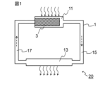
- FIG. 1 is a schematic cross-sectional view of a heat transport device in one embodiment of the present disclosure.
- 1 shows an XRD pattern of the material (TiCO) manufactured in Example 1.
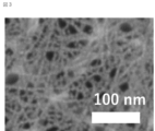
- An FE-SEM image of the material (TiCO) produced in Example 1 is shown.
- wick means a member used for heat transport. More specifically, “wick” refers to a member capable of transporting a working fluid in a liquid state by capillary force.
- the wick includes a material containing nanofibers and/or a two-dimensional substance.
- the term “material” simply means "a material containing nanofibers and/or a two-dimensional substance” (in other words, a material containing at least one of nanofibers and a two-dimensional substance).
- the material containing nanofibers and/or two-dimensional substances typically means a material that is solid and does not contain a binder or the like (for example, a polymer).
- a material containing nanofibers and/or a two-dimensional substance is, in a narrow sense, a material that essentially consists of at least one of nanofibers and a two-dimensional substance (including other objects or impurities that may be unavoidably mixed). good).
- materials including nanofibers and/or two-dimensional substances are not limited thereto.
- the material contained in the wick of this embodiment is a nanofiber (or nanofilament, hereinafter the same) of a predetermined material (substance) and/or a two-dimensional substance.
- the predetermined material that can be used in this embodiment is represented by the following formula (1).
- MQ a O b ...(1) (wherein, M is at least one element selected from the group consisting of groups 3, 4, 5, 6 and 7, and includes so-called early transition metals, such as Sc, Ti, Zr, Hf, V, Nb , Ta, Cr, Mo and Mn, preferably at least one element selected from the group consisting of Ti, V, Cr, Mo and Mn.
- Gain, Q is at least one element selected from the group consisting of Groups 12, 13, 14, 15 and 16 (excluding O), for example consisting of B, C, N, Si, P and S. may contain at least one element selected from the group; a is 0 or more and 2 or less, b is greater than 0 and less than or equal to 2)
- MQO predetermined material
- MQOs include materials represented by the formulas TiO 2 , TiCO, TiCON, VO 2 , VCO, VCON, CrO 2 , CrCO, CrCON, MoO 2 , MoCO, MoCON, MnO 2 , MnCO, MnCON, etc. It will be done.
- the M may be Ti and the Q may be C.
- a may be other than 0.
- the above-mentioned predetermined material may have a peak in the diffraction angle 2 ⁇ in the range of 2° or more and 10° or less in an X-ray diffraction (XRD) pattern.
- XRD X-ray diffraction
- MQO has a crystal structure different from a hexagonal system.
- the crystal structure of MQO can be considered to be anatase type, lepidocrocite type, or a mixture thereof at present.
- the crystal structure of MQO may be lepidocrocite type.
- MQO can be produced using the first raw material and the second raw material, for example, as follows.
- the first raw material contains at least the above M
- the second raw material contains at least the above Q
- the first raw material and the second raw material can react in a protic solvent to generate MQO.
- a material represented by the following formula (2) may be used as the first raw material.
- M c A 1 d ...(2) (In the formula, M is as above, A1 is at least one element selected from the group consisting of Groups 12, 13, 14, 15 and 16, for example selected from the group consisting of B, C, N, O, Si, P and S. may contain at least one element, c and d are each independently from 1 to 5)
- the material represented by formula (2) needs to be different from the MQO of the product.
- the material represented by formula (2) typically does not have a peak in the diffraction angle 2 ⁇ of 2° or more and 10° or less in an X-ray diffraction (XRD) pattern.
- XRD X-ray diffraction
- Examples of the first raw material represented by formula (2) include TiB 2 , TiB, TiC, TiN, TiO 2 , Ti 5 Si 3 , Ti 2 SbP, VO 2 , V 2 O 4 , NbC, Nb 2 O 5 , MoO 2 , MoO 3 , MoS 2 , MnO 2 , Mn 3 O 4 , MnCO 3 and the like.
- a material represented by the following formula (3) may be used as the first raw material.
- M m A 2 X n ...(3) (In the formula, M is as above, X is at least one element selected from the group consisting of C and N, n is 1 or more and 4 or less, m is greater than n and less than or equal to 5, A 2 is at least one element selected from the group consisting of Groups 12, 13, 14, 15 and 16, usually a Group A element, typically Group IIIA and Group IVA, and more details may contain at least one selected from the group consisting of Al, Ga, In, Tl, Si, Ge, Sn, Pb, P, As, S and Cd, preferably Al)
- the MAX phase has a layer composed of two A atoms located between two layers represented by M m X n (which may have a crystal lattice in which each X is located in an octahed
- a 2 atomic layer a layer of A 2 atoms
- the MAX phase is not limited to this.
- Examples of the first raw material represented by formula (3) include Ti 3 AlC 2 , Ti 3 GaC 2 , Ti 3 SiC 2 and the like.
- the material represented by formula (2) and the material represented by formula (3) may be used together (for example, as a mixture).
- An ion-binding substance having a carbon-containing group may be used as the second raw material.
- the ion-binding substance having a carbon-containing group contains C.
- Examples of the ion-binding substance include ammonium salts, phosphates, sulfates, and the like.
- a quaternary ammonium salt may be used as the second raw material.
- quaternary ammonium salts include tetramethylammonium hydroxide (TMAH), tetraethylammonium hydroxide (TEAH), tetrapropylammonium hydroxide (TPAH), tetrabutylammonium hydroxide (TBAH or TBAOH), benzyltrimethylammonium Hydroxide, Tetrabutylammonium Fluoride (TBAF), Tetrabutylammonium Chloride (TBACl), Tetrabutylammonium Bromide (TBAB), Tetrabutylammonium Iodide (TBAI), Benzyltriethylammonium Chloride (BTEAC), Hexadecyltrimethylammonium Bromide , cetyltrimethylammonium bromide (CTAB), benzethonium chloride, benzalkonium chloride, cetylpyridin
- ion-binding substances containing P and/or S may be used as the second raw material.
- the protic solvent may be any solvent as long as it can at least partially dissolve the first raw material and the second raw material, and in particular may be an aqueous solvent.
- aqueous solvent water, alcohol (eg, ethanol, 1-propanol, isopropanol), carboxylic acid (eg, acetic acid, formic acid), etc. are used.
- the aqueous solvent may be composed of water and optionally a liquid substance that is compatible with water (eg, a protic solvent other than water), and is preferably water.
- the first raw material and the second raw material are reacted in a protic solvent.
- the second raw material may be added to the protic solvent in advance.
- the proportion of the second raw material to the total of the protic solvent and the second raw material can be, for example, 5% by mass or more, especially 20% by mass or more, and/or can be, for example, 80% by mass or less, especially 50% by mass or less.
- the first raw material may be further added to the protic solvent to which the second raw material has been added and mixed. In such a mixture, the reaction that produces MQO proceeds.
- the temperature of the mixture (which may contain reaction products) (reaction temperature) may be, for example, 15° C. or higher, especially 40° C. or higher, and/or for example 100° C.
- the mixing time may be, for example, one or more days, especially two or more days, and/or it may be, for example, no more than 10 days, especially no more than 7 days.
- Mixing can be carried out, for example, by rotating and stirring a magnetic stirrer placed in a container while maintaining the reaction temperature with a hot plate stirrer and a hot water bath.
- the treatment operations and conditions that allow the reaction to proceed are not limited to those described above, and may be appropriately selected depending on the first raw material, second raw material, protic solvent, etc. to be used.
- MQO MQO
- the resulting MQO nanofibers can be in the form of nanoribbons extending in nanoscale width.
- a plurality of MQO nanofibers may be bonded and/or integrated with each other to grow into two-dimensionally extending nanoflakes.
- a plurality of MQO nanoflakes may overlap each other (eg, due to van der Waals forces) to form a laminate.
- the generation and growth of such MQO may be considered to be due to a bottom-up synthetic reaction (see, for example, Non-Patent Document 1).
- MQO is solid content.
- MQOs may typically be particles (or powders).
- the mixture after the reaction may be subjected to post-treatment as appropriate.
- post-treatments include, for example, washing, impact application (including application of shear force), drying (for example, freeze drying, heat drying), pulverization, and the like.
- Washing may be performed using a protic solvent. Similar explanations as above may apply for protic solvents, which may be washed with water or alcohol, for example. After washing, separation operations (centrifugation and/or decantation) may be performed. The washing and separation operations can be repeated until the pH of the supernatant after centrifugation becomes, for example, 8 or less.
- cleaning may be performed using an aqueous solution of a metal salt.
- the metal salt can be, for example, a halide (fluoride, chloride, bromide, iodide) of an alkali metal (Li, Na, K, etc.), typically LiCl, NaCl, KCl, etc.
- cleaning may be carried out using, for example, an aqueous metal salt solution having a concentration of 1 to 10 molar.
- separation operations centrifugation and/or decantation
- the washing and separation operations can be repeated as necessary until the pH of the supernatant after centrifugation becomes, for example, 8 or less.
- Shocks such as vibration and/or ultrasound may be applied during and/or after cleaning. This can promote the dispersion of MQO particles (for example, nanofibers/nanoflakes, hereinafter the same). If the MQO particles are aggregated, they can be disintegrated. Such an effect is significantly obtained when impact is applied during cleaning using an aqueous solution of a metal salt (it is thought that the metal cations derived from the metal salt can enter the gaps between the aggregates and disintegrate them). Shock can be applied using, for example, one or more of a handshake, an automatic shaker, a mechanical shaker, a vortex mixer, a homogenizer, an ultrasonic bath, and the like.
- a separation operation can be performed at any appropriate timing to remove unnecessary liquid components if present.
- a drying operation typically freeze-drying or thermal drying, may be carried out. Freeze-drying can be performed, for example, by freezing a mixture containing particles of MQO and a liquid component at any suitable temperature (eg, ⁇ 40° C.) and then drying it under a reduced pressure atmosphere. Thermal drying can be carried out, for example, by drying a mixture containing MQO particles and a liquid component at a temperature of 25° C. or higher (for example, 200° C. or lower) under normal pressure or a reduced pressure atmosphere.
- the pulverization can be carried out using, for example, a mortar and pestle combination, an IKA mill, etc., but is not particularly limited. Grinding may be carried out after drying.
- particles of MQO can be obtained as a material containing MQO.
- MQO particles for example, nanofibers (and in some cases, aggregates of MQO nanofibers, such as MQO nanoflakes, which are also collectively referred to as "MQO nanofibers, etc.") can be obtained.
- MQO is represented by formula (1)
- the material containing MQO does not need to consist only of the constituent elements of formula (1).
- the MQO-containing material may optionally include protons and/or metal cations.
- the MQO-containing material may optionally have a modification or termination T present on its surface selected from the group consisting of hydroxyl groups, chlorine atoms, oxygen atoms, and hydrogen and nitrogen atoms. It may have at least one kind.
- a material containing MQO may have two or more layers between which ammonium ions (e.g., quaternary ammonium cations) and metal cations ( For example, at least one selected from the group consisting of alkali metal ions and alkaline earth metal ions may be present.
- ammonium ions e.g., quaternary ammonium cations
- metal cations For example, at least one selected from the group consisting of alkali metal ions and alkaline earth metal ions may be present.
- Materials containing MQO may contain unreacted first raw materials and/or second raw materials as impurities, and may also contain substances derived from the first raw materials, second raw materials, and/or protic solvents. may include.
- N may exist (remain) in any form in the material containing MQO, such as MQO nanofibers.
- the material containing MQO may include ammonium ions and tetramethylammonium ions.
- the material containing MQO contains a relatively small amount of residual A atoms, for example, 10% by mass or less with respect to the original A atoms. Good too.
- the residual amount of A atoms may be preferably 8% by mass or less, more preferably 6% by mass or less. However, even if the residual amount of A atoms exceeds 10% by mass, there may be no problem depending on the usage conditions.
- Such a supernatant liquid can be made into a slurry containing MQO particles such as MQO nanofibers by directly diluting it with a liquid medium, or by mixing it with a liquid medium after drying.
- the wick of this embodiment can be manufactured by shaping (molding, cutting, etc.) a material containing MQO, such as MQO nanofibers, into a desired shape and size using any appropriate method.
- the wick of this embodiment may be a fibrous structure formed using MQO nanofibers or the like.
- Such fibrous structures can be produced, for example, by applying a slurry containing nanofibers of MQO onto a substrate by any suitable method (e.g., filtration, spraying, bar coating, spin coating, dipping, etc.), drying, and then It can be manufactured by removing the base material.
- the liquid medium contained in the slurry can be selected as appropriate, and includes, for example, protic solvents (the same explanations as above apply), aprotic solvents (such as tetrahydrofuran, methylene chloride, acetonitrile, acetone, N, N- (dimethylformamide, dimethyl sulfoxide, etc.), nonpolar solvents (eg, hexane, benzene, toluene, diethyl ether, chloroform, ethyl acetate), and the like.
- protic solvents such as tetrahydrofuran, methylene chloride, acetonitrile, acetone, N, N- (dimethylformamide, dimethyl sulfoxide, etc.
- nonpolar solvents eg, hexane, benzene, toluene, diethyl ether, chloroform, ethyl acetate
- the wick of this embodiment is obtained.
- the shape and dimensions of the wick of this embodiment can be appropriately selected depending on the desired use.
- a material containing MQO typically has a peak in the diffraction angle 2 ⁇ of 2° or more and 10° or less in an X-ray diffraction (XRD) pattern.
- XRD X-ray diffraction
- a c-axis oriented MQO membrane is installed in the XRD analyzer (for example, as in the example described later, the filter is removed after suction filtration). It is preferable to measure the self-supporting membrane obtained by arranging the surface that was in contact with the filter on the lower side.
- the material of this embodiment (more specifically, MQO) has a Raman shift of at least 275 to 295 cm -1 , 435 to 295 cm -1 in a Raman spectrum using a laser with a wavelength of 514 nm, although this embodiment is not limited to It may have peaks at 455 cm ⁇ 1 and 665 to 745 cm ⁇ 1 .
- the material of this embodiment (more specifically, MQO) has a Raman shift of 140 to 160 cm -1 and 275 to 295 cm in a Raman spectrum using a laser with a wavelength of 514 nm. -1 , 435-455 cm -1 , and 665-745 cm -1 .
- 140 to 160 cm ⁇ 1 is an anatase type peak.
- the material of this embodiment (more specifically, MQO) has a crystal structure of anatase type, lepidocrocite type, or a mixture of these, although the present embodiment is not limited thereto. More preferably, it has a lepidocrocite crystal structure.
- the material of this embodiment (more specifically, MQO) has a Raman shift of at least 275 to 295 cm -1 , 435 to 295 cm -1 in a Raman spectrum using a laser with a wavelength of 514 nm, although this embodiment is not limited to It may have peaks at 455 cm -1 and 665 to 745 cm -1 , and when the intensity of each peak is X, Y, and Z, X is the largest.
- the material of this embodiment (more specifically, MQO) has a Raman shift of at least 180 to 200 cm ⁇ 1 in a Raman spectrum using a laser with a wavelength of 514 nm,
- a Raman shift of at least 180 to 200 cm ⁇ 1 in a Raman spectrum using a laser with a wavelength of 514 nm When there are peaks at the positions of 275 to 295 cm -1 , 375 to 395 cm -1 , 435 to 455 cm -1 , and 665 to 745 cm -1 and the intensities of each peak are V, X, Y, Z, and W. It may take the form that X is the largest.
- the Raman spectrum is measured with a Raman spectrometer using a laser beam with a wavelength of 514 nm as an excitation light source (the vertical axis is intensity and the horizontal axis is Raman shift). Peaks in a Raman spectrum can be identified visually or using software used with a Raman spectrometer.
- the particle size of the particles of MQO can be, for example, 0.01 nm or more, especially 0.1 nm or more, even 1 nm or more, and/or can be, for example, less than 1000 nm, especially 100 nm or less, and even 50 nm or less. Such particles may also be referred to as nanoparticles.
- the particle morphology of MQO is nanofibers and/or two-dimensional materials.
- the two-dimensional material includes one or more of nanoflakes and laminates of nanoflakes. In this embodiment, the two-dimensional material is not limited to only nanoflakes and a laminate of nanoflakes.
- a material comprising MQO typically particles (e.g. nanofibers/nanoflakes) of MQO, e.g. nanofibers of MQO (and optionally aggregates of nanofibers of MQO, e.g. nanoflakes of MQO) ) is provided.
- MQO nanofibers have a hydrophilic surface and have nano-order cross-sectional dimensions.
- a wick containing such MQO nanofibers has a large ability to attract (e.g., suck up) a working fluid in a liquid state by capillary action, and therefore can transfer (e.g., suck up) a working fluid in a liquid state at a high speed. .
- the reason for this is that due to the nano-order cross-sectional dimensions, the volume density of the nanofibers in the wick is high, and the gaps between the nanofibers form a narrow space (flow path for the working fluid).
- the total surface area of the nanofibers obtained is large, and the hydrophilic surface makes it easier for a working fluid in a liquid state (typically, but not limited to, water) to wet and spread on the surface of the MQO nanofibers. This may be possible.
- nanofiber of MQO is a solid substance extending in the longitudinal direction, and the external dimensions of a cross section perpendicular to the longitudinal direction (cross-sectional external dimensions) are nano-order (i.e., 1 nm or more and 1000 nm or more). (less than 1 nm) or smaller than that (less than 1 nm, for example, 0.1 nm or more and less than 1 nm).
- the length of the MQO nanofibers in the longitudinal direction is not particularly limited. That is, the length of the nanofiber in the longitudinal direction is not limited to nano-order (ie, 1 nm or more and less than 1000 nm), but may be micron-order (1 ⁇ m or more and less than 1000 ⁇ m).
- the cross-sectional dimensions of the nanofibers can be, for example, 0.1 nm or more, especially 1 nm or more, and for example 100 nm or less, especially 50 nm or less, preferably 15 nm or less.
- a wick including MQO nanofibers or the like having such a small cross-sectional dimension can transport a working fluid in a liquid state at a higher velocity.
- MQO nanofibers having such small cross-sectional dimensions can be realized.
- the cross-sectional external dimensions of the MQO nanofibers mean the shortest distance passing through the center in a cross section that traverses the longitudinal direction of the MQO nanofibers.
- the shape of the cross section of the MQO nanofiber is not particularly limited, but may be approximated by, for example, a rectangle (rectangle, square, etc.) or an ellipse (oblate circle, perfect circle, etc.).
- the MQO nanofiber is in the form of a nanoribbon
- its cross-sectional shape can be approximated by a rectangle
- the cross-sectional external dimension can correspond to the short side length of the rectangle.
- the MQO nanofiber is in the form of a nanofilament
- its cross-sectional shape can be approximated by a flat circle
- the cross-sectional external dimensions can correspond to the short axis length of the flat circle.
- the BET specific surface area of a material containing MQO such as MQO nanofibers is not particularly limited, but may be, for example, 10 m 2 /g or more and 500 m 2 /g or less.
- BET specific surface area is the isothermal adsorption curve of nitrogen gas or other gases mentioned above under liquid nitrogen temperature (77 K) by an adsorption method using nitrogen gas or other suitable gas (e.g. krypton (Kr) gas, etc.). It is calculated using the BET formula.
- a "two-dimensional substance” has a two-dimensionally extending surface (also referred to as a plane or two-dimensional sheet surface), and the maximum dimension of the surface (which may correspond to the "in-plane dimension" of a particle) ), the thickness of which is nano-order (i.e., 1 nm or more and less than 1000 nm) or smaller sub-nano order (less than 1 nm, e.g. 0.1 nm or more and less than 1 nm). mean something
- the in-plane dimension is not limited to nano-order (ie, 1 nm or more and less than 1000 nm), but may be micron-order (1 ⁇ m or more and less than 1000 ⁇ m).
- the two-dimensional material includes one or more of nanoflakes and nanoflake stacks, as described above. Nanoflakes may also be referred to as nanosheets or two-dimensional (nano)sheets.
- the thickness of one layer of nanoflakes can be, for example, 0.01 nm or more, especially 0.8 nm or more, and eg 20 nm or less, especially 3 nm or less.
- the in-plane dimensions of the nanoflakes may be, for example, 0.1 ⁇ m or more, especially 1 ⁇ m or more, and for example 200 ⁇ m or less, especially 40 ⁇ m or less. Nanoflakes can be constructed by aggregating nanofibers.
- a stack of nanoflakes may also be referred to as a multilayer MQO.
- the distance (interlayer distance or void size) between two adjacent nanoflakes (or two adjacent layers of MQO) is not particularly limited.
- the above-mentioned dimensions are calculated using a scanning electron microscope (SEM), a transmission electron microscope (TEM), or an atomic force microscope (processed by a method such as a focused ion beam (FIB), if necessary).
- SEM scanning electron microscope
- TEM transmission electron microscope
- FIB focused ion beam
- real space calculated from the number average dimension (number average of at least 40) based on photographs observed with AFM) or the position on the reciprocal lattice space of the (002) plane measured by X-ray diffraction (XRD) method. It can be determined as a distance.
- XRD X-ray diffraction
- the cross-sectional external dimensions of MQO nanofibers are determined by exposing the cross-section of a wick containing MQO nanofibers using a method such as a focused ion beam (FIB), and then using a scanning electron microscope (SEM) or a transmission electron microscope (SEM) to examine the exposed cross-section. Take an image using a TEM, extract at least 40 MQO nanofibers in which a cross section crossing the longitudinal direction appears, and calculate the number average of their cross-sectional external dimensions. is required.
- FIB focused ion beam
- SEM scanning electron microscope
- SEM transmission electron microscope
- MQO is not limited to the above forms, but may have any suitable form.
- a heat transport device refers to a device that transports heat using a phase change of a working fluid.
- Phase change of the working fluid refers to evaporation and condensation.
- the heat transport device 20 of the present embodiment includes: A housing 1 having a space inside; A wick 3 disposed within the housing 1; A working fluid (not shown) sealed in the housing 1 in a state where it can come into contact with the wick 3; including.
- a working fluid (not shown) sealed in the housing 1 in a state where it can come into contact with the wick 3; including.
- the wick 3 the one described above in the first embodiment is used.
- FIG. 1 exemplarily shows a case where the heat transport device 20 is a loop-type heat pipe.
- the housing 1 includes an evaporator 11, a condenser 13, and a gas flow path 15 and a liquid flow path 17 that connect these, respectively.
- the passage 15 and the liquid flow passage 17 integrally constitute the internal space of the housing 1 .
- the wick 3 is placed within the evaporator 11.
- a working fluid (not shown) is sealed in the internal space of the housing 1 .
- the housing 1 is made of a thermally conductive material (for example, metal) at least in the evaporator 11 and the condenser 13.
- the working fluid is evaporated in the evaporator 11 (relatively high temperature part) to which heat is supplied from the outside (heat source), and the working fluid in a gaseous state moves in the gas flow path 15,
- the condenser 13 a relatively low-temperature part
- heat is released to the outside, and the working fluid, which has become a liquid, passes through the liquid flow path 17 to the evaporator 11 due to the capillary force of the wick 3. be transported (returned).
- the working fluid circulates within the housing 1 while changing its phase.
- the flow of the working fluid is schematically shown by dotted line arrows
- the supply of heat from the outside (heat input) and the radiation of heat to the outside (thermal output) are schematically shown by dotted line arrows.
- the working fluid in the liquid state can be transported at a high speed, and high heat transport performance can be obtained. , the maximum heat transport amount of the heat transport device 20 is improved.
- FIG. 1 shows a case where the heat transport device 20 is a loop-type heat pipe, but the heat transport device of this embodiment uses no wick except for using the wick 3 described above in Embodiment 1.
- the structure of a known heat transport device for example, a tubular heat pipe, a vapor chamber, etc. may be applied.
- the wick and the heat transport device in an embodiment of the present disclosure have been described above in detail, the present disclosure can be modified in various ways. Note that the wick of the present disclosure may be manufactured by a method different from the manufacturing method in the embodiments described above.
- Example 1 relates to the wick of Embodiment 1, which uses TiCO nanofibers.
- ⁇ Preparation of slurry containing TiCO nanofibers First, in a container (100 mL Eyeboy), 1 g of titanium diboride (TiB 2 , manufactured by Alfa Aesar) and 30 mL of a 25% by mass tetramethylammonium hydroxide (TMAH) aqueous solution (Tokyo (manufactured by Kasei Kogyo Co., Ltd.). A stirrer tip with a length approximately the same size (35 mm) as the inner diameter of the circular bottom of the container was placed there. While keeping the container at 50° C. in a water bath, the mixture in the container was stirred with a stirrer tip and maintained for 120 hours, thereby allowing the reaction to proceed.
- TMAH tetramethylammonium hydroxide
- the reaction mixture in the container was then transferred to a 50 mL centrifuge tube with a stainless steel spatula (without adding any liquid medium such as ethanol or water). Centrifugation was performed using a centrifuge at 3500 G for 5 minutes to sediment the solid content. (i) After centrifugation, discard the supernatant, (ii) add 40 mL of ethanol (manufactured by Fujifilm Wako Pure Chemical Industries, Ltd.) to the remaining sediment in the centrifuge tube, and handshake for 5 minutes (reslurry). (iii) Centrifugation was performed under the same conditions as above. These operations (i) to (iii) were repeated until the pH of the supernatant liquid became 8 or less.
- the pH of the supernatant liquid became 8 or less, so the supernatant liquid was discarded and the repeating operation was completed.
- 40 mL of pure water was added to the remaining sediment in the centrifuge tube, and the mixture was shaken and stirred for 15 minutes using an automatic shaker. Thereafter, centrifugation was performed using a centrifuge at 3500 G for 30 minutes, and the supernatant was collected as a sample slurry.
- the sample slurry obtained corresponds to a slurry containing TiCO nanofibers (see analysis results below).
- the wick sample prepared above was placed in a petri dish filled with water with the WT surface (1 cm x 100 ⁇ m) vertically placed on the top and bottom surfaces, and placed at a depth of about 1 mm. When it was soaked in water, water was sucked up to the top surface at a speed of 4 mm/s. From this result, the volume of water sucked up by the wick sample per unit area per unit time is 4 ⁇ 10 -3 m 3 /(m 2 s), and therefore the mass of water sucked up per unit area per unit time is , 4 kg/(m 2 ⁇ s) (specific gravity of water: 1000 kg/m 3 ). Since the heat of evaporation of water per unit mass at 25° C.
- the amount of heat that this wick sample can take away by evaporating water at 25° C. is calculated to be 9768 kW/m 2 . That is, in the wick sample of Example 1, the water transport speed was 4 mm/s, and the water heat transport performance at 25° C. was about 10 4 kW/m 2 .
- FIG. 3 shows an FE-SEM image. As can be seen from Figure 3, this material had a cross-sectional profile of approximately 5 nm.
- Comparative Example 1 relates to a wick using particles of MXene, which is a type of two-dimensional material.
- MAX particles precursor of MXene particles
- TiC powder, Ti powder, and Al powder all manufactured by Kojundo Kagaku Kenkyusho Co., Ltd.
- Al powder all manufactured by Kojundo Kagaku Kenkyusho Co., Ltd.
- the mixture was added and mixed for 24 hours.
- the obtained mixed powder was fired at 1350° C. for 2 hours in an Ar atmosphere.
- the fired body (block) thus obtained was ground with an end mill to a maximum size of 40 ⁇ m or less.
- Ti 3 AlC 2 particles were obtained as MAX particles.
- etching was performed under the following etching conditions to obtain a solid-liquid mixture (slurry) containing a solid component derived from the Ti 3 AlC 2 powder.
- Etching conditions ⁇ Precursor: Ti 3 AlC 2 (passed through a 45 ⁇ m sieve) ⁇ Etching solution composition: 49%HF 6mL 18 mL H2O HCl (12M) 36mL ⁇ Precursor input amount: 3.0g ⁇ Etching container: 100mL Eye Boy ⁇ Etching temperature: 35°C ⁇ Etching time: 24h ⁇ Stirrer rotation speed: 400 rpm
- the slurry was divided into two parts, inserted into two 50 mL centrifuge tubes, centrifuged at 3500 G using a centrifuge, and then the supernatant liquid was discarded.
- the operation of adding 40 mL of pure water to the remaining precipitate in each centrifuge tube, performing centrifugation again at 3500 G, and separating and removing the supernatant liquid was repeated 11 times. After the final centrifugation, the supernatant was discarded and the Ti 3 C 2 T x -water medium clay was obtained.
- this supernatant liquid was centrifuged using a centrifuge at 4300G for 2 hours, the supernatant liquid was discarded, and a single-layer/poor-layer MXene-containing clay was prepared as a mono-layer/poor-layer MXene-containing sample. I got it.
- the wick sample prepared above was placed in a petri dish filled with water with the WT surface (1 cm x 100 ⁇ m) vertically placed on the top and bottom surfaces, and placed at a depth of about 1 mm. When it was soaked in water, it was unable to absorb water at all (the suction height was 0 mm).
- Comparative Example 2 relates to a wick using a sintered body (porous metal sintered body) of metal powder (copper powder).
- wick Copper powder with an average particle size D50 of 50 ⁇ m was used as the metal powder, and acrylic resin (binder) and copper powder were mixed at a volume ratio of 1:1.
- the resulting mixture was heat treated at 400° C. for 1 hour to burn off the acrylic resin and obtain a porous metal sintered body.
- the obtained porous metal sintered body was cut to obtain a wick sample having a width (W) of 1 cm, a length (L) of 2 cm, and a thickness (T) of 100 ⁇ m.
- wick sample prepared above was placed in a petri dish filled with water with the WT surface (1 cm x 100 ⁇ m) vertically placed on the top and bottom surfaces, and placed at a depth of about 1 mm. When it was soaked in water, water was sucked up to the top surface at a speed of 0.5 mm/s. From this result, the wick sample of Comparative Example 2 has a water transfer rate of 0.5 mm/s, and according to the same calculation as Example 1, the water heat transfer performance at 25°C is approximately 10 3 kW/m. It was 2 .
- Comparative Example 3 relates to a wick using a sintered body (porous metal sintered body) of metal powder (titanium powder).
- the wick of the present disclosure can be used in a heat transport device that utilizes phase change of a working fluid to transport the working fluid by capillary force.
- the heat transport device of the present disclosure can be incorporated into an electronic device and used to release (remove) heat from a heat source of the electronic device.
- the wick and heat transport device of the present disclosure can be used not only in these applications but also in any suitable application.
- a wick used for heat transport The formula below: MQ a O b (wherein M is at least one element selected from the group consisting of Groups 3, 4, 5, 6, and 7; Q is at least one element selected from the group consisting of Groups 12, 13, 14, 15 and 16 (excluding O), a is 0 or more and 2 or less, b is greater than 0 and less than or equal to 2)
- a heat transport device that utilizes phase change of a working fluid A housing having a space inside; The wick according to any one of ⁇ 1> to ⁇ 3>, disposed within the housing; a working fluid sealed within the housing so as to be in contact with the wick; heat transport equipment, including
Landscapes
- Engineering & Computer Science (AREA)
- Life Sciences & Earth Sciences (AREA)
- Sustainable Development (AREA)
- Physics & Mathematics (AREA)
- Thermal Sciences (AREA)
- Mechanical Engineering (AREA)
- General Engineering & Computer Science (AREA)
- Chemical & Material Sciences (AREA)
- Chemical Kinetics & Catalysis (AREA)
- General Chemical & Material Sciences (AREA)
- Textile Engineering (AREA)
- Physical Or Chemical Processes And Apparatus (AREA)
Abstract
Description
以下の式:
MQaOb
(式中、Mは、第3、4、5、6および7族からなる群より選択される少なくとも1種の元素であり、
Qは、第12、13、14、15および16族からなる群より選択される少なくとも1種の元素(但し、Oを除く)であり、
aは、0以上2以下であり、
bは、0より大きく、2以下である)
で表されるナノファイバーおよび/または2次元物質を含む材料
を含む、ウィックが提供される。
内部に空間を有する筐体と、
前記筐体内に配置された、前記ウィックと、
前記ウィックと接触可能な状態で、前記筐体内に封入された作動流体と、
を含む、熱輸送装置が提供される。
本実施形態は、ウィックに関する。本開示において、「ウィック」は、熱輸送のために使用される部材を意味する。より詳細には、「ウィック」は、液体状態の作動流体を毛細管力により移送可能な部材を意味する。
MQaOb ・・・(1)
(式中、Mは、第3、4、5、6および7族からなる群より選択される少なくとも1種の元素であり、いわゆる早期遷移金属、例えばSc、Ti、Zr、Hf、V、Nb、Ta、Cr、MoおよびMnからなる群より選択される少なくとも1種の元素を含み得、好ましくは、Ti、V、Cr、MoおよびMnからなる群より選択される少なくとも1種の元素を含み得、
Qは、第12、13、14、15および16族からなる群より選択される少なくとも1種の元素(但し、Oを除く)であり、例えばB、C、N、Si、PおよびSからなる群より選択される少なくとも1種の元素を含み得、
aは、0以上2以下であり、
bは、0より大きく、2以下である)
McA1 d ・・・(2)
(式中、Mは、上記の通りであり、
A1は、第12、13、14、15および16族からなる群より選択される少なくとも1種の元素であり、例えばB、C、N、O、Si、PおよびSからなる群より選択される少なくとも1種の元素を含み得、
cおよびdは、それぞれ互いに独立して、1以上5以下である)
但し、式(2)で表される材料は、生成物のMQOと相違することを要する。式(2)で表される材料は、代表的には、X線回折(XRD)パターンにおいて回折角2θが2°以上10°以下の範囲にピークを有しないものであり得る。
MmA2Xn ・・・(3)
(式中、Mは、上記の通りであり、
Xは、CおよびNからなる群より選択される少なくとも1種の元素であり、
nは、1以上4以下であり、
mは、nより大きく、5以下であり、
A2は、第12、13、14、15および16族からなる群より選択される少なくとも1種の元素であり、通常はA族元素、代表的にはIIIA族およびIVA族であり、より詳細にはAl、Ga、In、Tl、Si、Ge、Sn、Pb、P、As、SおよびCdからなる群より選択される少なくとも1種を含み得、好ましくはAlである)
MAX相は、MmXnで表される2つの層(各XがMの八面体アレイ内に位置する結晶格子を有し得る)の間に、A2原子により構成される層が位置した結晶構造を有する。MAX相は、代表的にm=n+1の場合、n+1層のM原子の層の各間にX原子の層が1層ずつ配置され(これらを合わせて「MmXn層」とも称する)、n+1番目のM原子の層の次の層としてA2原子の層(「A2原子層」)が配置された繰り返し単位を有する。しかしながら、MAX相はこれに限定されない。
本実施形態は、熱輸送装置に関する。本開示において、「熱輸送装置」は、作動流体の相変化を利用して熱を輸送する装置を意味する。作動流体の相変化は、蒸発および凝縮を意味する。
内部に空間を有する筐体1と、
筐体1内に配置されたウィック3と、
ウィック3と接触可能な状態で、筐体1内に封入された作動流体(図示せず)と、
を含む。ウィック3は、実施形態1にて上述したものを使用する。
実施例1は、実施形態1のウィックであって、TiCOのナノファイバーを使用したウィックに関する。
まず、容器(100mLアイボーイ)に、二ホウ化チタン(TiB2、Alfa Aesar社製)1gと、25質量%のテトラメチルアンモニウムヒドロキシド(TMAH)水溶液30mL(東京化成工業株式会社製)とを投入した。そこに、容器の円形底面の内径とほぼ同じサイズ(35mm)の長さのスターラーチップを入れた。容器を水浴で50℃に保ちながら、容器内の混合物をスターラーチップで攪拌し120時間維持し、これにより反応を進行させた。次に、容器内の反応混合物を(エタノールや水等の液状媒体を添加することなく)ステンレス製スパチュラで50mL遠沈管に移した。遠心分離機を用いて3500Gおよび5分間の条件で遠心分離を行って固形分を沈降させた。(i)遠心分離後、上澄み液を廃棄し、(ii)遠沈管中の残りの沈降物にエタノール(富士フイルム和光純薬株式会社製)40mLを加え、ハンドシェイクを5分間行い(リスラリー)、(iii)上記と同条件で遠心分離を行った。この(i)~(iii)の操作を、上澄み液のpHが8以下になるまで繰り返した。3回繰り返したところで上澄み液のpHが8以下になったので、この上澄み液を廃棄して、繰返し操作を終了とした。遠沈管中の残りの沈降物に純水40mLを加え、オートマチックシェイカーを用いて15分間振とう攪拌した。その後、遠心分離機を用いて3500Gおよび30分間の条件で遠心分離を行って、上澄み液をサンプルスラリーとして回収した。得られたサンプルスラリーが、TiCOナノファイバーを含むスラリーに該当する(下記の分析結果を参照のこと)。
上記で調製したサンプルスラリーを、ヌッチェを用いて一晩吸引ろ過した。吸引ろ過のフィルターには、メンブレンフィルター(デュラポア、孔径0.45μm、メルク株式会社製)を用いた。吸引ろ過後、フィルター上の前駆体膜を真空オーブンで80℃にて一晩乾燥させ、フィルターを除去して、自立膜を得た。得られた自立膜を長方形に切断して、幅(W)1cm、長さ(L)2cm、厚さ(T)100μmのウィックサンプルを得た。
上記で作製したウィックサンプルを、WT面(1cm×100μm)が上端面および下端面になるように垂直に立てた状態で、水を入れたシャーレに配置して、約1mmの深さで水に漬けたところ、水を上端面まで4mm/sの速度で吸い上げた。この結果から、ウィックサンプルが、単位時間単位面積あたりの吸い上げる水の体積は、4×10-3m3/(m2・s)であり、よって、単位時間単位面積あたりの吸い上げる水の質量は、4kg/(m2・s)となる(水の比重:1000kg/m3)。25℃における単位質量あたりの水の蒸発熱は、2442kJ/kgであることから、このウィックサンプルが、25℃における水の蒸発による奪える熱量は、9768kW/m2と計算される。すなわち、実施例1のウィックサンプルは、水の移送速度が4mm/sであり、25℃での水の熱輸送性能が約104kW/m2であった。
上記と同様にして得られた自立膜をX線光電子分光法(XPS)で分析しところ、得られたXPSスペクトルにおいて、Ti 2p、C 1s、O 1s、N 1sに対応するピークが認められ、よって、Ti、C、O、Nが検出された。Nは、原料のTMAHの残留分であると考えられことから、自立膜の材料は、Ti、C、Oから構成されると考えられる。
また、上記と同様にして得られた自立膜について、XRD装置(株式会社リガク製、MiniFlex)を用いてXRDプロファイルを測定した(特性X線:CuKα=1.54Å)。得られたXRDパターンを図2に示す。図2から理解されるとおり、この材料は、2θ=7.26°にピークを有していた。
比較例1は、二次元材料の1種であるMXeneの粒子を使用したウィックに関する。
TiC粉末、Ti粉末およびAl粉末(いずれも株式会社高純度化学研究所製)を2:1:1のモル比で、ジルコニアボールを入れたボールミルに投入して24時間混合した。得られた混合粉末をAr雰囲気下にて1350℃で2時間焼成した。これにより得られた焼成体(ブロック)をエンドミルで最大寸法40μm以下まで粉砕した。これにより、MAX粒子としてTi3AlC2粒子を得た。
上記方法で調製したTi3AlC2粒子(粉末)を用い、下記エッチング条件でエッチングを行って、Ti3AlC2粉末に由来する固体成分を含む固液混合物(スラリー)を得た。
(エッチング条件)
・前駆体:Ti3AlC2(目開き45μmふるい通し)
・エッチング液組成:49%HF 6mL
H2O 18mL
HCl(12M) 36mL
・前駆体投入量:3.0g
・エッチング容器:100mLアイボーイ
・エッチング温度:35℃
・エッチング時間:24h
・スターラー回転数:400rpm
上記スラリーを2分割して、50mL遠沈管2本にそれぞれ挿入し、遠心分離機を用いて3500Gの条件で遠心分離を行った後、上澄み液を廃棄した。各遠沈管中の残りの沈殿物に純水40mLを追加し、再度3500Gで遠心分離を行って上澄み液を分離除去する操作を11回繰り返した。最終遠心分離後に、上澄み液を廃棄し、Ti3C2Tx-水分媒体クレイを得た。
上記方法で調製したTi3C2Tx-水分媒体クレイに対し、下記条件の通り、Li含有化合物としてLiClを用い、20℃以上25℃以下で12時間撹拌して、Liインターカレーションを行った。
(Liのインターカレーションの条件)
・Ti3C2Tx-水分媒体クレイ(洗浄後MXene):固形分0.75g
・LiCl:0.75g
・インターカレーション容器:100mLアイボーイ
・温度:20℃以上25℃以下(室温)
・時間:10h
・スターラー回転数:800rpm
上記Ti3C2Tx-水分媒体クレイに(i)純水40mLを追加してからシェーカーで15分間撹拌後に、(ii)3500Gで遠心分離し、(iii)上澄み液を単層MXene含有液として回収した。この(i)~(iii)の操作を、合計4回繰り返して、単層MXene含有上澄み液を得た。さらに、この上澄み液を、遠心分離機を用いて4300G、2時間の条件で遠心分離を行った後、上澄み液を廃棄し、単層・少層MXene含有試料として単層・少層MXene含有クレイを得た。
このMXene含有クレイと純水とを適切な量で混合して、固形分濃度(MXene粒子濃度)が34mg/mLのサンプルスラリーを準備した。得られたサンプルスラリーが、MXene粒子を含むスラリー(MXene-水分散体)に該当する。
上記で調製したサンプルスラリーを用いたこと以外は、実施例1と同様にして、幅(W)1cm、長さ(L)2cm、厚さ(T)100μmのウィックサンプルを得た。
上記で作製したウィックサンプルを、WT面(1cm×100μm)が上端面および下端面になるように垂直に立てた状態で、水を入れたシャーレに配置して、約1mmの深さで水に漬けたところ、水を吸い上げることは全くできなかった(吸い上げ高さゼロmm)。
比較例2は、金属粉(銅粉)の焼結体(多孔質金属焼結体)を使用したウィックに関する。
金属粉として、平均粒径D50が50μmの銅粉を用い、アクリル樹脂(バインダー)と銅粉とを体積比1:1で混合した。得られた混合物を400℃で1時間の熱処理に付して、アクリル樹脂を燃焼除去して、多孔質金属焼結体を得た。得られた多孔質金属焼結体を切断して、幅(W)1cm、長さ(L)2cm、厚さ(T)100μmのウィックサンプルを得た。
上記で作製したウィックサンプルを、WT面(1cm×100μm)が上端面および下端面になるように垂直に立てた状態で、水を入れたシャーレに配置して、約1mmの深さで水に漬けたところ、水を上端面まで0.5mm/sの速度で吸い上げた。この結果から、比較例2のウィックサンプルは、水の移送速度が0.5mm/sであり、実施例1と同様の計算により、25℃での水の熱輸送性能が約103kW/m2であった。
比較例3は、金属粉(チタン粉)の焼結体(多孔質金属焼結体)を使用したウィックに関する。
金属粉として、平均粒径D50が50μmのチタン粉を用いたこと以外は、比較例2と同様にして、幅(W)1cm、長さ(L)2cm、厚さ(T)100μmのウィックサンプルを得た。
上記で作製したウィックサンプルを、比較例2と同様に評価したところ、水を上端面まで0.5mm/sの速度で吸い上げた。この結果から、比較例3のウィックサンプルは、水の移送速度が0.5mm/sであり、25℃での水の熱輸送性能が約103kW/m2であった。
熱輸送のために使用されるウィックであって、
以下の式:
MQaOb
(式中、Mは、第3、4、5、6および7族からなる群より選択される少なくとも1種の元素であり、
Qは、第12、13、14、15および16族からなる群より選択される少なくとも1種の元素(但し、Oを除く)であり、
aは、0以上2以下であり、
bは、0より大きく、2以下である)
で表される材料のナノファイバー
を含む、ウィック。
<2>
前記ナノファイバーの前記材料が、X線回折パターンにおいて回折角2θが2°以上10°以下の範囲にピークを有する、<1>に記載のウィック。
<3>
前記ナノファイバーが、1nm以上15nm以下の断面外形寸法を有する、<1>または<2>に記載のウィック。
<4>
作動流体の相変化を利用した熱輸送装置であって、
内部に空間を有する筐体と、
前記筐体内に配置された、<1>~<3>のいずれかに記載のウィックと、
前記ウィックと接触可能な状態で、前記筐体内に封入された作動流体と、
を含む、熱輸送装置。
3 ウィック
11 蒸発器
13 凝縮器
15 気体流路
17 液体流路
20 熱輸送装置
Claims (8)
- 熱輸送のために使用されるウィックであって、
以下の式:
MQaOb
(式中、Mは、第3、4、5、6および7族からなる群より選択される少なくとも1種の元素であり、
Qは、第12、13、14、15および16族からなる群より選択される少なくとも1種の元素(但し、Oを除く)であり、
aは、0以上2以下であり、
bは、0より大きく、2以下である)
で表されるナノファイバーおよび/または2次元物質を含む材料
を含む、ウィック。 - 前記ナノファイバーおよび/または2次元物質を含む材料が、X線回折パターンにおいて回折角2θが2°以上10°以下の範囲にピークを有する、請求項1に記載のウィック。
- 前記ナノファイバーおよび/または2次元物質を含む材料が、波長514nmのレーザーを用いたラマンスペクトルにおいて、ラマンシフトが140~160cm-1、275~295cm-1、435~455cm-1、および665~745cm-1の位置にピークを有する、請求項1または2に記載のウィック。
- 前記ナノファイバーおよび/または2次元物質を含む材料が、アナターゼ型またはレピドクロサイト型、もしくはこれらが混在した結晶構造を有する、請求項1~3のいずれかに記載のウィック。
- 前記ナノファイバーおよび/または2次元物質を含む材料が、レピドクロサイト型の結晶構造を有する、請求項1~4のいずれかに記載のウィック。
- 前記ナノファイバーおよび/または2次元物質を含む材料が、波長514nmのレーザーを用いたラマンスペクトルにおいて、ラマンシフトが少なくとも180~200cm-1、275~295cm-1、375~395cm-1、435~455cm-1、および665~745cm-1の位置にピークを有し、それぞれのピークの強度をV、X、Y、Z、Wとした場合にXが最も大きい、請求項1~5のいずれかに記載のウィック。
- 前記ナノファイバーが、1nm以上15nm以下の断面外形寸法を有する、請求項1~6のいずれかに記載のウィック。
- 作動流体の相変化を利用した熱輸送装置であって、
内部に空間を有する筐体と、
前記筐体内に配置された、請求項1~7のいずれかに記載のウィックと、
前記ウィックと接触可能な状態で、前記筐体内に封入された作動流体と、
を含む、熱輸送装置。
Priority Applications (2)
| Application Number | Priority Date | Filing Date | Title |
|---|---|---|---|
| CN202380039461.7A CN119096108A (zh) | 2022-05-13 | 2023-05-12 | 芯体和热传输装置 |
| JP2024520505A JPWO2023219168A1 (ja) | 2022-05-13 | 2023-05-12 |
Applications Claiming Priority (2)
| Application Number | Priority Date | Filing Date | Title |
|---|---|---|---|
| JP2022-079566 | 2022-05-13 | ||
| JP2022079566 | 2022-05-13 |
Publications (1)
| Publication Number | Publication Date |
|---|---|
| WO2023219168A1 true WO2023219168A1 (ja) | 2023-11-16 |
Family
ID=88730395
Family Applications (1)
| Application Number | Title | Priority Date | Filing Date |
|---|---|---|---|
| PCT/JP2023/017973 Ceased WO2023219168A1 (ja) | 2022-05-13 | 2023-05-12 | ウィックおよび熱輸送装置 |
Country Status (4)
| Country | Link |
|---|---|
| US (1) | US20250067521A1 (ja) |
| JP (1) | JPWO2023219168A1 (ja) |
| CN (1) | CN119096108A (ja) |
| WO (1) | WO2023219168A1 (ja) |
Cited By (1)
| Publication number | Priority date | Publication date | Assignee | Title |
|---|---|---|---|---|
| WO2025127031A1 (ja) * | 2023-12-13 | 2025-06-19 | 株式会社村田製作所 | 熱伝導材料 |
Citations (7)
| Publication number | Priority date | Publication date | Assignee | Title |
|---|---|---|---|---|
| JPS53145471U (ja) * | 1977-04-19 | 1978-11-16 | ||
| US20060151153A1 (en) * | 2005-01-07 | 2006-07-13 | Hon Hai Precision Industry Co., Ltd. | Heat dissipation system |
| JP2006348346A (ja) * | 2005-06-16 | 2006-12-28 | Nissan Motor Co Ltd | 吸水材、熱伝導部材、及びその製造方法 |
| US20100200199A1 (en) * | 2006-03-03 | 2010-08-12 | Illuminex Corporation | Heat Pipe with Nanostructured Wick |
| JP2015169411A (ja) * | 2014-03-10 | 2015-09-28 | 富士通株式会社 | 熱輸送デバイスとその製造方法、及び電子機器 |
| US20200149820A1 (en) * | 2014-11-04 | 2020-05-14 | Roccor, Llc | Conformal thermal ground planes |
| US20200340756A1 (en) * | 2019-04-26 | 2020-10-29 | Nanotek Instruments, Inc. | Graphene-enhanced vapor-based heat transfer device |
-
2023
- 2023-05-12 JP JP2024520505A patent/JPWO2023219168A1/ja active Pending
- 2023-05-12 WO PCT/JP2023/017973 patent/WO2023219168A1/ja not_active Ceased
- 2023-05-12 CN CN202380039461.7A patent/CN119096108A/zh not_active Withdrawn
-
2024
- 2024-11-12 US US18/944,213 patent/US20250067521A1/en active Pending
Patent Citations (7)
| Publication number | Priority date | Publication date | Assignee | Title |
|---|---|---|---|---|
| JPS53145471U (ja) * | 1977-04-19 | 1978-11-16 | ||
| US20060151153A1 (en) * | 2005-01-07 | 2006-07-13 | Hon Hai Precision Industry Co., Ltd. | Heat dissipation system |
| JP2006348346A (ja) * | 2005-06-16 | 2006-12-28 | Nissan Motor Co Ltd | 吸水材、熱伝導部材、及びその製造方法 |
| US20100200199A1 (en) * | 2006-03-03 | 2010-08-12 | Illuminex Corporation | Heat Pipe with Nanostructured Wick |
| JP2015169411A (ja) * | 2014-03-10 | 2015-09-28 | 富士通株式会社 | 熱輸送デバイスとその製造方法、及び電子機器 |
| US20200149820A1 (en) * | 2014-11-04 | 2020-05-14 | Roccor, Llc | Conformal thermal ground planes |
| US20200340756A1 (en) * | 2019-04-26 | 2020-10-29 | Nanotek Instruments, Inc. | Graphene-enhanced vapor-based heat transfer device |
Cited By (1)
| Publication number | Priority date | Publication date | Assignee | Title |
|---|---|---|---|---|
| WO2025127031A1 (ja) * | 2023-12-13 | 2025-06-19 | 株式会社村田製作所 | 熱伝導材料 |
Also Published As
| Publication number | Publication date |
|---|---|
| US20250067521A1 (en) | 2025-02-27 |
| JPWO2023219168A1 (ja) | 2023-11-16 |
| CN119096108A (zh) | 2024-12-06 |
Similar Documents
| Publication | Publication Date | Title |
|---|---|---|
| Anwer et al. | Nature-inspired, graphene-wrapped 3D MoS2 ultrathin microflower architecture as a high-performance anode material for sodium-ion batteries | |
| Lambert et al. | Synthesis and characterization of titania− graphene nanocomposites | |
| Guo et al. | Tunable synthesis of yolk–shell porous silicon@ carbon for optimizing Si/C-based anode of lithium-ion batteries | |
| JP5937653B2 (ja) | 炭素材料及びその製造方法 | |
| US20200220170A1 (en) | Porous silicon compositions and devices and methods thereof | |
| Zhang et al. | N-Doped hierarchically porous carbon derived from heterogeneous core–shell ZIF-L (Zn)@ ZIF-67 for supercapacitor application | |
| Wu et al. | Hemicellulose-triggered high-yield synthesis of carbon dots from biomass | |
| WO2024053514A1 (ja) | 2次元物質のナノフレークを含む材料およびその製造方法 | |
| US20230242407A1 (en) | Conductive two-dimensional particle and method for producing same, conductive film, conductive composite material, and conductive paste | |
| WO2012165753A1 (en) | The method for producing graphene by chemical exfoliation | |
| CN103911151B (zh) | 一种荧光性能可调的硫磷氮共掺杂碳点及其制备方法 | |
| JP2014123564A (ja) | 酸化グラフェンおよび四価バナジウムオキソ水酸化物の自己組織化複合体 | |
| Ai et al. | Formation of graphene oxide gel via the π-stacked supramolecular self-assembly | |
| US20250067521A1 (en) | Wick and heat transport device | |
| Duraia et al. | Humic acid-derived graphene–SnO2 nanocomposites for high capacity lithium-ion battery anodes | |
| WO2022050114A1 (ja) | 導電性2次元粒子およびその製造方法 | |
| US20240296969A1 (en) | Two-dimensional particle, conductive film, conductive paste, and method for producing two-dimensional particle | |
| US20250388740A1 (en) | Two-dimensional particle-containing composition and production method for two-dimensional particle-containing composition | |
| WO2024135617A1 (ja) | 水素吸着材および水素吸着装置 | |
| EP2755259A1 (en) | Self-assembled composite of graphene oxide and H4V3O8 | |
| WO2025084249A1 (ja) | Voc吸着材およびvoc吸着装置 | |
| Qi et al. | A facile non-hydrothermal fabrication of uniform α-MoO3 nanowires in high yield | |
| WO2024237308A1 (en) | Carbon dioxide/nitrogen/argon adsorbent and carbon dioxide/nitrogen/argon adsorption apparatus | |
| JPH08133716A (ja) | カーボンナノカプセル及びその製造方法 | |
| WO2024237307A1 (ja) | メタン吸着材およびメタン吸着装置 |
Legal Events
| Date | Code | Title | Description |
|---|---|---|---|
| 121 | Ep: the epo has been informed by wipo that ep was designated in this application |
Ref document number: 23803642 Country of ref document: EP Kind code of ref document: A1 |
|
| WWE | Wipo information: entry into national phase |
Ref document number: 2024520505 Country of ref document: JP |
|
| WWE | Wipo information: entry into national phase |
Ref document number: 202380039461.7 Country of ref document: CN |
|
| NENP | Non-entry into the national phase |
Ref country code: DE |
|
| 122 | Ep: pct application non-entry in european phase |
Ref document number: 23803642 Country of ref document: EP Kind code of ref document: A1 |