WO2023219093A1 - 垂直放射型rf送信機 - Google Patents
垂直放射型rf送信機 Download PDFInfo
- Publication number
- WO2023219093A1 WO2023219093A1 PCT/JP2023/017520 JP2023017520W WO2023219093A1 WO 2023219093 A1 WO2023219093 A1 WO 2023219093A1 JP 2023017520 W JP2023017520 W JP 2023017520W WO 2023219093 A1 WO2023219093 A1 WO 2023219093A1
- Authority
- WO
- WIPO (PCT)
- Prior art keywords
- antenna
- section
- transmitter
- housing
- board
- Prior art date
- Legal status (The legal status is an assumption and is not a legal conclusion. Google has not performed a legal analysis and makes no representation as to the accuracy of the status listed.)
- Ceased
Links
Images



Classifications
-
- H—ELECTRICITY
- H04—ELECTRIC COMMUNICATION TECHNIQUE
- H04B—TRANSMISSION
- H04B1/00—Details of transmission systems, not covered by a single one of groups H04B3/00 - H04B13/00; Details of transmission systems not characterised by the medium used for transmission
- H04B1/02—Transmitters
- H04B1/03—Constructional details, e.g. casings, housings
-
- H—ELECTRICITY
- H01—ELECTRIC ELEMENTS
- H01Q—ANTENNAS, i.e. RADIO AERIALS
- H01Q1/00—Details of, or arrangements associated with, antennas
- H01Q1/12—Supports; Mounting means
- H01Q1/22—Supports; Mounting means by structural association with other equipment or articles
- H01Q1/24—Supports; Mounting means by structural association with other equipment or articles with receiving set
-
- H—ELECTRICITY
- H01—ELECTRIC ELEMENTS
- H01Q—ANTENNAS, i.e. RADIO AERIALS
- H01Q1/00—Details of, or arrangements associated with, antennas
- H01Q1/02—Arrangements for de-icing; Arrangements for drying-out ; Arrangements for cooling; Arrangements for preventing corrosion
-
- H—ELECTRICITY
- H01—ELECTRIC ELEMENTS
- H01Q—ANTENNAS, i.e. RADIO AERIALS
- H01Q1/00—Details of, or arrangements associated with, antennas
- H01Q1/12—Supports; Mounting means
- H01Q1/22—Supports; Mounting means by structural association with other equipment or articles
- H01Q1/24—Supports; Mounting means by structural association with other equipment or articles with receiving set
- H01Q1/248—Supports; Mounting means by structural association with other equipment or articles with receiving set provided with an AC/DC converting device, e.g. rectennas
-
- H—ELECTRICITY
- H01—ELECTRIC ELEMENTS
- H01Q—ANTENNAS, i.e. RADIO AERIALS
- H01Q1/00—Details of, or arrangements associated with, antennas
- H01Q1/52—Means for reducing coupling between antennas; Means for reducing coupling between an antenna and another structure
- H01Q1/526—Electromagnetic shields
-
- H—ELECTRICITY
- H01—ELECTRIC ELEMENTS
- H01Q—ANTENNAS, i.e. RADIO AERIALS
- H01Q19/00—Combinations of primary active antenna elements and units with secondary devices, e.g. with quasi-optical devices, for giving the antenna a desired directional characteristic
- H01Q19/10—Combinations of primary active antenna elements and units with secondary devices, e.g. with quasi-optical devices, for giving the antenna a desired directional characteristic using reflecting surfaces
- H01Q19/104—Combinations of primary active antenna elements and units with secondary devices, e.g. with quasi-optical devices, for giving the antenna a desired directional characteristic using reflecting surfaces using a substantially flat reflector for deflecting the radiated beam, e.g. periscopic antennas
-
- H—ELECTRICITY
- H01—ELECTRIC ELEMENTS
- H01Q—ANTENNAS, i.e. RADIO AERIALS
- H01Q19/00—Combinations of primary active antenna elements and units with secondary devices, e.g. with quasi-optical devices, for giving the antenna a desired directional characteristic
- H01Q19/10—Combinations of primary active antenna elements and units with secondary devices, e.g. with quasi-optical devices, for giving the antenna a desired directional characteristic using reflecting surfaces
- H01Q19/108—Combination of a dipole with a plane reflecting surface
-
- H—ELECTRICITY
- H01—ELECTRIC ELEMENTS
- H01Q—ANTENNAS, i.e. RADIO AERIALS
- H01Q21/00—Antenna arrays or systems
- H01Q21/24—Combinations of antenna units polarised in different directions for transmitting or receiving circularly and elliptically polarised waves or waves linearly polarised in any direction
-
- H—ELECTRICITY
- H01—ELECTRIC ELEMENTS
- H01Q—ANTENNAS, i.e. RADIO AERIALS
- H01Q21/00—Antenna arrays or systems
- H01Q21/24—Combinations of antenna units polarised in different directions for transmitting or receiving circularly and elliptically polarised waves or waves linearly polarised in any direction
- H01Q21/26—Turnstile or like antennas comprising arrangements of three or more elongated elements disposed radially and symmetrically in a horizontal plane about a common centre
-
- H—ELECTRICITY
- H01—ELECTRIC ELEMENTS
- H01Q—ANTENNAS, i.e. RADIO AERIALS
- H01Q21/00—Antenna arrays or systems
- H01Q21/28—Combinations of substantially independent non-interacting antenna units or systems
-
- H—ELECTRICITY
- H01—ELECTRIC ELEMENTS
- H01Q—ANTENNAS, i.e. RADIO AERIALS
- H01Q9/00—Electrically-short antennas having dimensions not more than twice the operating wavelength and consisting of conductive active radiating elements
- H01Q9/04—Resonant antennas
- H01Q9/30—Resonant antennas with feed to end of elongated active element, e.g. unipole
- H01Q9/42—Resonant antennas with feed to end of elongated active element, e.g. unipole with folded element, the folded parts being spaced apart a small fraction of the operating wavelength
-
- H—ELECTRICITY
- H01—ELECTRIC ELEMENTS
- H01Q—ANTENNAS, i.e. RADIO AERIALS
- H01Q9/00—Electrically-short antennas having dimensions not more than twice the operating wavelength and consisting of conductive active radiating elements
- H01Q9/04—Resonant antennas
- H01Q9/44—Resonant antennas with a plurality of divergent straight elements, e.g. V-dipole, X-antenna; with a plurality of elements having mutually inclined substantially straight portions
-
- H—ELECTRICITY
- H01—ELECTRIC ELEMENTS
- H01Q—ANTENNAS, i.e. RADIO AERIALS
- H01Q1/00—Details of, or arrangements associated with, antennas
- H01Q1/12—Supports; Mounting means
- H01Q1/22—Supports; Mounting means by structural association with other equipment or articles
- H01Q1/2208—Supports; Mounting means by structural association with other equipment or articles associated with components used in interrogation type services, i.e. in systems for information exchange between an interrogator/reader and a tag/transponder, e.g. in Radio Frequency Identification [RFID] systems
- H01Q1/2216—Supports; Mounting means by structural association with other equipment or articles associated with components used in interrogation type services, i.e. in systems for information exchange between an interrogator/reader and a tag/transponder, e.g. in Radio Frequency Identification [RFID] systems used in interrogator/reader equipment
Definitions
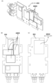
- FIG. 8 is an example of an explanatory diagram illustrating the housing 400 that houses the holding section 600, the first antenna substrate 20, and the like.
- FIG. 9 is an example of an explanatory diagram illustrating the spatial positional relationship of the main board 10, the first antenna board 20, and the second antenna board 30 housed in the casing 400 of FIG.
- FIG. 10 is an example of an explanatory diagram illustrating the configuration of the reflection section 300.
- FIG. 11 is an example of an explanatory diagram illustrating the reflection section 300 on which the main substrate 10 is stacked.
- FIG. 12 is an example of an explanatory diagram illustrating a second embodiment of the transmitter 1.
- FIG. 13 is an example of an explanatory diagram illustrating a plurality of different embodiments of the transmitter 1.
- FIG. 14 is an example of an explanatory diagram for explaining the radiation direction of electromagnetic waves.
- FIG. 15 is an example of an explanatory diagram illustrating the radiation direction of electromagnetic waves in the transmitter 1 of FIG. 12.
- FIG. 16 is an example of an explanatory diagram illustrating the performance of the transmitter 1 according to the second embodiment shown in FIG. 12.
- FIG. 17 is an example of an explanatory diagram illustrating another configuration example of the transmitter 1.
- FIG. 18 is an example of an explanatory diagram illustrating the performance of the transmitter 1 shown in FIG. 17.
- FIG. 19 is an example of an explanatory diagram illustrating still another configuration example of the transmitter 1.
- FIG. 20 is an example of an explanatory diagram illustrating the performance of the transmitter 1 shown in FIG. 18.
- FIG. 20 is an example of an explanatory diagram illustrating the performance of the transmitter 1 shown in FIG. 18.
- FIG. 21 is an example of an explanatory diagram illustrating another example of the configuration of the transmitter 1.
- FIG. 22 is an example of an explanatory diagram illustrating the performance of the transmitter 1 shown in FIG. 21.
- FIG. 23 is an example of an explanatory diagram illustrating the radiation direction of electromagnetic waves in the transmitter 1 shown in FIG. 21.
- FIG. 24 is an example of an explanatory diagram illustrating a comparison when using various antennas.
- the first electronic devices 2A are, for example, sensors 2a, 2b, 2c, 2d, . . . .
- the sensors 2a, 2b, 2c, and 2d are, for example, a light sensor, a temperature sensor, an audio sensor (e.g., a microphone), an optical sensor (e.g., a camera, a visible light sensor, an invisible light sensor, etc.), a proximity sensor, a touch sensor, a force sensor, It can be a vibration sensor, a direction sensor, a motion sensor (eg an accelerometer or speed sensor), a thermal sensor, a resistive sensor, a magnetic sensor, a millimeter wave sensor, a CO2 sensor, etc.
- the electronic devices 2 (2A, 2B) are connected to a management server 3, a management terminal 4, an air conditioner 6, a lighting device 7, etc. via a network 5, for example, so that data can be communicated, and in particular, so that data can be communicated with each other. has been done.
- the electronic device 2 may be fixed in position within the space in which the transmitter 1 is attached, but it may be configured to be movable within the space, for example, together with a larger device to which an actuator is attached. It's okay.
- power transmission targets include mobile phones, PDAs (personal digital assistants), wireless microphones, wireless USB, wireless theaters, wireless televisions, wireless cameras, wireless headphones, wireless mice, wireless keyboards, wireless Other electronic devices such as routers, wireless printers, etc. may also be used.
- the transceiver 206 transmits the status of the power management unit 203, the status of the functional unit or drive unit 208, information acquired by the functional unit such as a sensor or the drive unit 208, etc. to an external transmitter via the transmitting/receiving antenna unit 205. Send to 1.
- the transmitting/receiving antenna section 205 is preferably configured as an inverted F-type antenna, for example.
- the transmitting/receiving antenna section 205 configured as an inverted F-type antenna is configured to function as a 2.4 GHz band data communication antenna, for example.
- FIG. 4 is an example of an explanatory diagram illustrating the components of the transmitter 1. As shown in FIG. FIG. 4(A) is a sectional view of the transmitter 1 according to the first embodiment. FIG. 4(B) is an exploded view of the transmitter 1 according to the first embodiment.
- FIG. 4 It can be seen from FIG. 4 that a plurality of components of the transmitter 1 are housed within the housing 400.
- the accommodation space of the casing 400 that accommodates the plurality of components of the transmitter 1 is closed by the reflection section 300 as if it were a lid.
- the electromagnetic waves emitted from the first antenna section 21 and the electromagnetic waves emitted from the first antenna section 21 and reflected by the reflecting section 300 are overlapped and directed from the first antenna section 21 toward the housing 400. radiated to.
- the distance from the first antenna section 21 to the reflecting section 300 is about 25 mm.
- the distance from the first antenna section 21 to the reflecting section 300 can be in the range of ⁇ /16 to ⁇ /4. Even if the distance between the first antenna section 21 and the reflection section 300 is set to about ⁇ /16, it is possible to maintain antenna efficiency of 90% or more. Spacing is optimal. However, considering the heights of the input section 15 and output section 16, which are power/communication connectors, ⁇ /13 is selected in the configuration of FIG. 4.
- the interval between the first antenna section 21 and the reflecting section 300 is set to about ⁇ /4, so that the phase of the radio wave from the first antenna section 21 and the phase of the radio wave reflected from the reflecting section 300 are in the same phase. By doing so, antenna efficiency can be maximized.
- the housing 400 includes, in its housing space, a main board 10 having a shielding part 17 and a heat conducting part 18, a first antenna board 20 connected to the main board 10 via a cable 22, and a cable 32.
- the second antenna board 30 connected to the main board 10 via the main board 10, a holding part 600 for holding the first antenna board 20 on the inner surface of the housing 400, and the like are accommodated.
- FIG. 5(B) is an explanatory diagram illustrating an example in which the cable 22 is guided along a route different from that in FIG. 5(A).
- the cable 22 extends in the attitude direction of the transmitter 1 along the boss 410, but in the embodiment of FIG. 5(B), the cable 22 extends along the boss 410. extends along the long side of.
- the first antenna board 20 is connected to the main board 10 via the first cable 22, the first antenna board 20 has a substantially rectangular shape, and the first cable 22 has a substantially rectangular shape. It is guided from the long side to the first antenna substrate 20 and connected to the first antenna section 21 .
- the configuration of the first antenna section 21 provided on the first antenna substrate 20 is not limited to the above-described configuration.
- the first antenna section 21 includes a first antenna element 21a and a second antenna element 21b, the first antenna element 21a has a common shape with the second antenna element 21b, The first antenna element 21a further includes an additional path section, and the first antenna element 21a outputs an electromagnetic wave having a phase different from that of the electromagnetic wave output from the second antenna element.
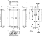
- FIG. 10 is an example of an explanatory diagram illustrating the configuration of the reflection section 300.
- FIG. 10A is an example of an explanatory diagram illustrating the inner surface 310 of the reflecting portion 300.
- FIG. 10(B) is an example of an explanatory diagram illustrating the reflection section outer surface 320 of the reflection section 300.
- a reflective section inner surface 310 of the reflective section 300 shown in FIG. 10(A) is a surface that faces the housing 400 and comes into contact with the housing 400.
- a recess 311, such as a groove or a notch, into which the sealing part 330 can be fitted is formed around the inner surface 310 of the reflecting part.
- the reflecting section 300 can be manufactured at low cost if it is manufactured from metal having the same composition by casting or die casting. However, each part of the reflective section 300 may be manufactured using a metal having a different composition, for example, by a lamination method (3D printing) or the like.
- a fixing device 324 such as a screw, is inserted into the fixing device insertion hole 323, and the fixing device 324 is further inserted into a boss 410 provided on the housing 400 to fix the reflecting part 300 and the housing 400. Connect to.
- the mounting structure 322 may be configured to be able to fix an additional fixture, such as a DIN rail fixture, using screws or the like. Further, the mounting structure 322 preferably has a structure that allows the transmitter 1 to be mounted by selecting the orientation thereof, for example, a structure that allows the transmitter 1 to be mounted either vertically or horizontally.
- the antenna can be installed on the back side of the case lid (non-metallic case) 1210 of the case 1200 (inner side facing the case lower part 1220). Further, in the transmitter 1, it is preferable that the lower part (metal housing) 1220 of the housing 1200 is made of a metal body.
- the lower part 1220 of the casing which serves as a heat sink and a reflective part, is preferably made of metal such as aluminum. Such a configuration is good because the lower housing 1220 can be made lighter, easier to process, and lower in price.
- the housing lid (non-metallic housing) 1210 and the housing lower part (metallic housing) 1220 are arranged substantially parallel to each other.
- the transmitter 1 has a low profile structure in the radiation direction Dr.
- the transmitter 1 has a main radiation direction Dr of electromagnetic waves in the normal direction of mutually parallel surfaces of a housing lid (non-metallic housing) 1210 and a housing lower part (metallic housing) 1220 (FIGS. 14 and 15). have.
- FIG. 13 is an example of an explanatory diagram illustrating a plurality of different configuration examples of the transmitter 1.
- the nonmetallic housing 1210 has a substantially cylindrical shape, and has a space therein for accommodating a substrate, an antenna, and the like.
- the metal housing 1220 has a substantially disk shape and is configured to cover the non-metal housing 1210.
- the non-metallic housing 1210 and the metal housing 1220 are configured to form a substantially cylindrical shape by combining them. Furthermore, the non-metal casing 1210 and the metal casing 1220 are each formed hollow, and accommodate a common substrate, antenna, etc. inside these hollow spaces.
- FIG. 13B shows a configuration in which the non-metallic housing 1210 and the metallic housing 1220 are each divided into halves of a cylindrical body, the ratio of division can be arbitrarily designed. It is possible.
- the non-metal casing 1210 and the metal casing 1220 are configured to form a substantially rectangular parallelepiped shape by combining them. Further, a hollow portion exists inside the substantially rectangular parallelepiped formed by the non-metallic casing 1210 and the metal casing 1220, and a common substrate, antenna, etc. can be accommodated in the hollow portion.
- the shape of the present transmitter 1, particularly the shape of the housing 1200 of the present transmitter 1, can be formed in various shapes such as a box shape, a spherical shape, a cylindrical shape, a cylindrical shape, and a polygonal shape.
- the transmitter may have a structure in which the antenna is wound around a cylinder or a prism, or a structure in which the shape of the casing of the present transmitter has a circular or triangular cross-sectional shape.
- the non-metallic housing 1210 is located closer to the front of the page in the radiation direction Dr than the metal housing (casing and antenna reflector) 1220.
- the metal housing (housing and antenna reflection plate) 1220 is located on the upstream side in the traveling direction of the radiation direction Dr
- the non-metallic housing 1210 is located on the downstream side in the traveling direction of the radiation direction Dr. .
- FIG. 14(B) shows that, like the transmitter 1 in FIG. 13(B), a non-metallic housing 1210 and a metal housing 1220 are lined up when viewed in the radiation direction Dr of electromagnetic waves radiated from the antenna 1400.
- 1 illustrates a transmitter 1 arranged;
- antenna 1450 is directly connected to signal generation board 1460.
- antenna 1450 may be formed on signal generation substrate 1460.
- a configuration may also be adopted in which a hollow space is provided between the antenna 1450 and the signal generation board 1460, and the antenna 1450 and the signal generation board 1460 are connected by a cable as shown in FIG.
- the electromagnetic waves emitted from the antenna 1400 directly pass through the non-metallic housing 1210 and are radiated out of the transmitter 1 in the radiation direction Dr in the top view.
- the electromagnetic waves radiated from the antenna 1400 in the direction of the metal housing 1220 are reflected by the metal housing 1220 that functions as a reflecting section, and are radiated in the radiation direction Dr in the top view.
- the electromagnetic waves directly radiated from the antenna 1400 in the Dr direction and the electromagnetic waves reflected by the metal casing 1220 and radiated in the Dr direction overlap and pass through the non-metal casing 1210. Then, it is radiated.
- These overlapping electromagnetic waves are radiated in the radiation direction Dr, that is, in the side view, in the depth direction of the plane of the paper.
- the radiation direction Dr of the transmitter 1 is perpendicular to the outer surfaces of the non-metallic housing 1210 and the metal housing 1220 that are substantially parallel to each other, and The direction is from 1220 to non-metallic housing 1210 .
- FIG. 16 is an example of an explanatory diagram illustrating the performance of the transmitter 1 according to the second embodiment shown in FIG. 12.
- FIG. 16 shows the results of a simulation performed by the applicant on a computer using a mathematical model for the transmitter 1.
- FIG. 16(A) is an example of an explanatory diagram illustrating the radiation efficiency of the transmitter 1 according to the second embodiment shown in FIG. 12.
- FIG. 16(B) is an example of an explanatory diagram illustrating the directivity (absolute gain ratio) of the transmitter 1 according to the second embodiment shown in FIG. 12.
- the transmitter 1 according to the second example has good radiation efficiency in the 920 MHz band, and in particular at 918 MHz, it has a radiation efficiency of 97.8%. There is. Moreover, as can be seen from FIG. 16(B), the transmitter 1 according to the second example has a directivity of about 6.1 dBi at 918 MHz.
- the appearance of the transmitter 1 shown in FIG. 17 is similar to the transmitter 1 according to the configuration examples shown in FIGS. 12 and 15.
- the transmitter 1 according to this configuration example has a dipole antenna 1250 similar to the configuration example of FIG. 15, and further includes a loop antenna 1700.
- FIG. 18 is an example of an explanatory diagram illustrating the performance of the transmitter 1 shown in FIG. 17.
- FIG. 18 shows the results of a simulation performed by the applicant on a computer using a mathematical model for the transmitter 1.
- FIG. 18(A) is an example of an explanatory diagram illustrating the radiation efficiency of the transmitter 1 shown in FIG. 17.
- 18(B) and 18(C) are examples of explanatory diagrams illustrating the directivity (absolute gain ratio) of dipole antenna 1250 and loop antenna 1700 of transmitter 1 shown in FIG. 17, respectively.
- Transmitter 1 has a dipole antenna similar to dipole antenna 1250 in FIGS. 15 and 17.
- the transmitter 1 has a polarization rotating cross dipole antenna 1900 configured by combining the pair of dipole antennas described above.
- the transmitter 1 according to this configuration example can radiate rotatable polarized waves as described below using a polarization rotating cross dipole antenna 1900.
- the phase adjustment section 1930 is preferably arranged in a region near the center of the substrate 1240. Further, the phase adjustment section 1930 may be configured such that the dipole antenna consisting of the second antenna section 1920 and the phase adjustment section 1930 is out of phase with respect to the dipole antenna consisting of the first antenna section 1910.
- the above-mentioned phase shift caused by the phase adjustment section 1930 is preferably about ⁇ /4, for example. Based on such a phase shift, the transmitter 1 shown in FIG. 19 can radiate rotatably polarized waves.
- FIG. 20(A) is an example of an explanatory diagram illustrating the radiation efficiency of the transmitter 1 according to this configuration example.
- FIG. 20(B) is an example of an explanatory diagram illustrating the directivity (absolute gain ratio) of the transmitter 1 shown in FIG. 19.
- FIG. 20C is an example of an explanatory diagram illustrating the rotatability of the transmitter 1 shown in FIG. 19.
- the polarization rotating cross dipole antenna 1900 has directivity in the normal direction of the substrate 1240 and in the direction from the metal housing 1220 to the non-metal housing 1210. can be confirmed.
- the heat sink 2100 is preferably exposed to the outside of the housing 1200 through the heat sink opening 2120.
- the heat sink 2100 is preferably exposed to the outside of the housing 1200 through the heat sink opening 2120. It is better if it is exposed to the outside.
- the control device may be, for example, a single board computer equipped with a processor.
- the control device may be, for example, Raspberry Pi.
- the control device can also be realized by edge computing implemented using Python (registered trademark) or the like on a Raspberry Pi.
- the control device can also be realized by a microcomputer, an ASIC (application specific integrated circuit), or a PLC (programmable logic controller).
Landscapes
- Engineering & Computer Science (AREA)
- Computer Networks & Wireless Communication (AREA)
- Signal Processing (AREA)
- Physics & Mathematics (AREA)
- Electromagnetism (AREA)
- Transmitters (AREA)
Priority Applications (4)
| Application Number | Priority Date | Filing Date | Title |
|---|---|---|---|
| EP23803568.7A EP4525315A4 (en) | 2022-05-10 | 2023-05-10 | VERTICAL RADIATING RF TRANSMITTER |
| JP2024520463A JPWO2023219093A1 (cg-RX-API-DMAC7.html) | 2022-05-10 | 2023-05-10 | |
| CN202380034997.XA CN119054205A (zh) | 2022-05-10 | 2023-05-10 | 垂直放射型rf发送器 |
| US18/864,072 US20250329915A1 (en) | 2022-05-10 | 2023-05-10 | Vertical-emitting rf transmitter |
Applications Claiming Priority (2)
| Application Number | Priority Date | Filing Date | Title |
|---|---|---|---|
| JP2022-077719 | 2022-05-10 | ||
| JP2022077719 | 2022-05-10 |
Publications (1)
| Publication Number | Publication Date |
|---|---|
| WO2023219093A1 true WO2023219093A1 (ja) | 2023-11-16 |
Family
ID=88730228
Family Applications (1)
| Application Number | Title | Priority Date | Filing Date |
|---|---|---|---|
| PCT/JP2023/017520 Ceased WO2023219093A1 (ja) | 2022-05-10 | 2023-05-10 | 垂直放射型rf送信機 |
Country Status (5)
| Country | Link |
|---|---|
| US (1) | US20250329915A1 (cg-RX-API-DMAC7.html) |
| EP (1) | EP4525315A4 (cg-RX-API-DMAC7.html) |
| JP (1) | JPWO2023219093A1 (cg-RX-API-DMAC7.html) |
| CN (1) | CN119054205A (cg-RX-API-DMAC7.html) |
| WO (1) | WO2023219093A1 (cg-RX-API-DMAC7.html) |
Cited By (1)
| Publication number | Priority date | Publication date | Assignee | Title |
|---|---|---|---|---|
| WO2026121249A1 (ja) * | 2024-12-03 | 2026-06-11 | エイターリンク株式会社 | 送信機の取付構造 |
Citations (3)
| Publication number | Priority date | Publication date | Assignee | Title |
|---|---|---|---|---|
| WO2020084841A1 (ja) | 2018-10-24 | 2020-04-30 | 住友電気工業株式会社 | アンテナモジュール、及び車両 |
| JP2022007184A (ja) * | 2020-06-25 | 2022-01-13 | 加賀Fei株式会社 | 通信装置 |
| JP2022077719A (ja) | 2020-11-12 | 2022-05-24 | キヤノン株式会社 | トナー |
Family Cites Families (4)
| Publication number | Priority date | Publication date | Assignee | Title |
|---|---|---|---|---|
| US6329954B1 (en) * | 2000-04-14 | 2001-12-11 | Receptec L.L.C. | Dual-antenna system for single-frequency band |
| SE530103C2 (sv) * | 2006-07-06 | 2008-03-04 | Cbg Holding Ab | Antennlåda för till exempel TV-mottagning och ett förfarande för tillverkning av sagda antennlåda |
| CN101715617B (zh) * | 2007-06-04 | 2013-08-07 | 皮雷利&C.有限公司 | 包括极化和空间分集天线系统的无线网络装置 |
| SE537623C2 (sv) * | 2012-07-20 | 2015-08-11 | Cbg Holding Ab | Antennbox och metod för att producera densamma |
-
2023
- 2023-05-10 EP EP23803568.7A patent/EP4525315A4/en active Pending
- 2023-05-10 JP JP2024520463A patent/JPWO2023219093A1/ja active Pending
- 2023-05-10 US US18/864,072 patent/US20250329915A1/en active Pending
- 2023-05-10 CN CN202380034997.XA patent/CN119054205A/zh active Pending
- 2023-05-10 WO PCT/JP2023/017520 patent/WO2023219093A1/ja not_active Ceased
Patent Citations (3)
| Publication number | Priority date | Publication date | Assignee | Title |
|---|---|---|---|---|
| WO2020084841A1 (ja) | 2018-10-24 | 2020-04-30 | 住友電気工業株式会社 | アンテナモジュール、及び車両 |
| JP2022007184A (ja) * | 2020-06-25 | 2022-01-13 | 加賀Fei株式会社 | 通信装置 |
| JP2022077719A (ja) | 2020-11-12 | 2022-05-24 | キヤノン株式会社 | トナー |
Non-Patent Citations (4)
| Title |
|---|
| ANONYMOUS: "Building Management. Environmental sensors with low maintenance costs", AETERLINK HOMEPAGE, 24 January 2022 (2022-01-24), XP093107216, Retrieved from the Internet <URL:https://web.archive.org/web/20220124224336/https://aeterlink.com/services/building_management/> [retrieved on 20231130] * |
| See also references of EP4525315A4 |
| TANABE YUJI; CHANG TAMMY; YEH ALEXANDER J.; POON ADA S. Y.: "A Small Dual-Band Asymmetric Dipole Antenna for 13.56 MHz Power and 2.45 GHz Data Transmission", IEEE ANTENNAS AND WIRELESS PROPAGATION LETTERS, IEEE, PISCATAWAY, NJ, US, vol. 13, 1 January 1900 (1900-01-01), US , pages 1120 - 1123, XP011551917, ISSN: 1536-1225, DOI: 10.1109/LAWP.2014.2330496 * |
| VERMA SHALIN; RANO DINESH; MALHOTRA SAMBHAV; HASHMI MOHAMMAD S.: "Measurements and Characterization of a Newly Developed Novel Miniature WIPT System", IEEE TRANSACTIONS ON INSTRUMENTATION AND MEASUREMENT, IEEE, USA, vol. 70, 3 May 2021 (2021-05-03), USA, pages 1 - 11, XP011855237, ISSN: 0018-9456, DOI: 10.1109/TIM.2021.3075537 * |
Cited By (1)
| Publication number | Priority date | Publication date | Assignee | Title |
|---|---|---|---|---|
| WO2026121249A1 (ja) * | 2024-12-03 | 2026-06-11 | エイターリンク株式会社 | 送信機の取付構造 |
Also Published As
| Publication number | Publication date |
|---|---|
| CN119054205A (zh) | 2024-11-29 |
| US20250329915A1 (en) | 2025-10-23 |
| EP4525315A4 (en) | 2026-05-13 |
| JPWO2023219093A1 (cg-RX-API-DMAC7.html) | 2023-11-16 |
| EP4525315A1 (en) | 2025-03-19 |
Similar Documents
| Publication | Publication Date | Title |
|---|---|---|
| KR102639492B1 (ko) | 안테나 모듈 및 이를 포함하는 전자 장치 | |
| KR102639423B1 (ko) | 안테나 장치 및 이를 포함하는 전자 장치 | |
| KR102612938B1 (ko) | 안테나 모듈을 포함하는 전자 장치 | |
| TW201431176A (zh) | 電子裝置及其天線單元 | |
| JP2012231266A (ja) | アンテナ装置 | |
| KR20210056000A (ko) | 안테나 및 그것을 포함하는 전자 장치 | |
| US12206190B2 (en) | Antenna, wireless communication device, and antenna forming method | |
| KR20220163658A (ko) | 안테나를 포함하는 전자 장치 | |
| KR20240071958A (ko) | 안테나를 포함하는 전자 장치 | |
| EP4525315A1 (en) | Vertical radiation-type rf transmitter | |
| KR102930431B1 (ko) | 안테나를 포함하는 전자 장치 | |
| KR20230048913A (ko) | 안테나를 포함하는 전자 장치 | |
| EP1950831A1 (en) | Dipole array directional antenna | |
| KR20240043629A (ko) | 안테나를 포함하는 전자 장치 | |
| KR20230109048A (ko) | 안테나를 포함하는 전자 장치 | |
| KR20230041534A (ko) | 안테나를 포함하는 전자 장치 | |
| KR20230026738A (ko) | 안테나를 포함하는 전자 장치 | |
| KR20230046910A (ko) | 안테나를 포함하는 전자 장치 | |
| KR20240133491A (ko) | 안테나를 포함하는 전자 장치 | |
| JP7803604B1 (ja) | 垂直放射型rf送信機 | |
| TWI501463B (zh) | 無線收發裝置及其天線模組 | |
| JP2004320075A (ja) | チップアンテナ、アンテナユニットおよびそれを用いた無線通信カード | |
| CN113140889A (zh) | 移动装置 | |
| KR20220046416A (ko) | 안테나 장치 및 그를 포함하는 전자 장치 | |
| CN117650360B (zh) | 一种天线结构和电子设备 |
Legal Events
| Date | Code | Title | Description |
|---|---|---|---|
| 121 | Ep: the epo has been informed by wipo that ep was designated in this application |
Ref document number: 23803568 Country of ref document: EP Kind code of ref document: A1 |
|
| WWE | Wipo information: entry into national phase |
Ref document number: 2024520463 Country of ref document: JP |
|
| WWE | Wipo information: entry into national phase |
Ref document number: 202380034997.X Country of ref document: CN |
|
| WWE | Wipo information: entry into national phase |
Ref document number: 18864072 Country of ref document: US |
|
| WWE | Wipo information: entry into national phase |
Ref document number: 2023803568 Country of ref document: EP |
|
| NENP | Non-entry into the national phase |
Ref country code: DE |
|
| ENP | Entry into the national phase |
Ref document number: 2023803568 Country of ref document: EP Effective date: 20241210 |
|
| WWP | Wipo information: published in national office |
Ref document number: 18864072 Country of ref document: US |