WO2023219041A1 - インタラクション装置 - Google Patents
インタラクション装置 Download PDFInfo
- Publication number
- WO2023219041A1 WO2023219041A1 PCT/JP2023/017156 JP2023017156W WO2023219041A1 WO 2023219041 A1 WO2023219041 A1 WO 2023219041A1 JP 2023017156 W JP2023017156 W JP 2023017156W WO 2023219041 A1 WO2023219041 A1 WO 2023219041A1
- Authority
- WO
- WIPO (PCT)
- Prior art keywords
- electrode
- interaction device
- outer shell
- user
- sensor
- Prior art date
- Legal status (The legal status is an assumption and is not a legal conclusion. Google has not performed a legal analysis and makes no representation as to the accuracy of the status listed.)
- Ceased
Links
Images



Classifications
-
- A—HUMAN NECESSITIES
- A63—SPORTS; GAMES; AMUSEMENTS
- A63H—TOYS, e.g. TOPS, DOLLS, HOOPS OR BUILDING BLOCKS
- A63H9/00—Special methods or compositions for the manufacture of dolls, toy animals, toy figures, or parts thereof
-
- A—HUMAN NECESSITIES
- A63—SPORTS; GAMES; AMUSEMENTS
- A63F—CARD, BOARD, OR ROULETTE GAMES; INDOOR GAMES USING SMALL MOVING PLAYING BODIES; VIDEO GAMES; GAMES NOT OTHERWISE PROVIDED FOR
- A63F13/00—Video games, i.e. games using an electronically generated display having two or more dimensions
- A63F13/20—Input arrangements for video game devices
- A63F13/24—Constructional details thereof, e.g. game controllers with detachable joystick handles
-
- G—PHYSICS
- G06—COMPUTING OR CALCULATING; COUNTING
- G06F—ELECTRIC DIGITAL DATA PROCESSING
- G06F3/00—Input arrangements for transferring data to be processed into a form capable of being handled by the computer; Output arrangements for transferring data from processing unit to output unit, e.g. interface arrangements
- G06F3/01—Input arrangements or combined input and output arrangements for interaction between user and computer
-
- G—PHYSICS
- G06—COMPUTING OR CALCULATING; COUNTING
- G06F—ELECTRIC DIGITAL DATA PROCESSING
- G06F3/00—Input arrangements for transferring data to be processed into a form capable of being handled by the computer; Output arrangements for transferring data from processing unit to output unit, e.g. interface arrangements
- G06F3/01—Input arrangements or combined input and output arrangements for interaction between user and computer
- G06F3/03—Arrangements for converting the position or the displacement of a member into a coded form
- G06F3/041—Digitisers, e.g. for touch screens or touch pads, characterised by the transducing means
-
- G—PHYSICS
- G06—COMPUTING OR CALCULATING; COUNTING
- G06F—ELECTRIC DIGITAL DATA PROCESSING
- G06F3/00—Input arrangements for transferring data to be processed into a form capable of being handled by the computer; Output arrangements for transferring data from processing unit to output unit, e.g. interface arrangements
- G06F3/01—Input arrangements or combined input and output arrangements for interaction between user and computer
- G06F3/03—Arrangements for converting the position or the displacement of a member into a coded form
- G06F3/041—Digitisers, e.g. for touch screens or touch pads, characterised by the transducing means
- G06F3/044—Digitisers, e.g. for touch screens or touch pads, characterised by the transducing means by capacitive means
-
- G—PHYSICS
- G06—COMPUTING OR CALCULATING; COUNTING
- G06F—ELECTRIC DIGITAL DATA PROCESSING
- G06F3/00—Input arrangements for transferring data to be processed into a form capable of being handled by the computer; Output arrangements for transferring data from processing unit to output unit, e.g. interface arrangements
- G06F3/01—Input arrangements or combined input and output arrangements for interaction between user and computer
- G06F3/048—Interaction techniques based on graphical user interfaces [GUI]
- G06F3/0487—Interaction techniques based on graphical user interfaces [GUI] using specific features provided by the input device, e.g. functions controlled by the rotation of a mouse with dual sensing arrangements, or of the nature of the input device, e.g. tap gestures based on pressure sensed by a digitiser
-
- A—HUMAN NECESSITIES
- A63—SPORTS; GAMES; AMUSEMENTS
- A63H—TOYS, e.g. TOPS, DOLLS, HOOPS OR BUILDING BLOCKS
- A63H2200/00—Computerized interactive toys, e.g. dolls
-
- G—PHYSICS
- G06—COMPUTING OR CALCULATING; COUNTING
- G06F—ELECTRIC DIGITAL DATA PROCESSING
- G06F2203/00—Indexing scheme relating to G06F3/00 - G06F3/048
- G06F2203/041—Indexing scheme relating to G06F3/041 - G06F3/045
- G06F2203/04105—Pressure sensors for measuring the pressure or force exerted on the touch surface without providing the touch position
Definitions
- the present invention relates to an interaction device.
- interaction devices for controlling information processing devices such as home games have generally been made of a material that is relatively difficult to elastically deform, such as plastic.
- a stuffed toy-like device with an exterior such as fur can be considered as an interaction device.
- the user feels that the user has touched the tip of the hair, but if the contact sensor of the interaction device is placed relatively deep inside the interaction device, the user feels that the tip of the hair has been touched. In some cases, it may not be possible to detect contact that is as strong as the first touch.
- the present invention has been made in view of the above-mentioned circumstances, and one of its objects is to provide an interaction device that can improve the flexibility of the exterior.
- One aspect of the present invention that solves the above-mentioned problems of the conventional example is an interaction device that includes an outer shell made of an elastic material and at least one stationary member disposed near the surface of the outer shell.
- the capacitive sensor includes a substrate portion having elasticity and at least one sensor electrode disposed on the substrate portion.
- the degree of freedom in designing the exterior of the interaction device can be improved.
- FIG. 1 is a schematic explanatory diagram showing a schematic configuration of an interaction device 1 according to an embodiment of the present invention.
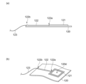
- 1 is a schematic cross-sectional view and a perspective view illustrating an example of a capacitance sensor included in an interaction device 1 according to an embodiment of the present invention.
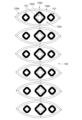
- FIG. 2 is a schematic plan view showing an example of a capacitance sensor included in the interaction device 1 according to the embodiment of the present invention.
- 1 is a configuration block diagram showing an example of a circuit section included in an interaction device 1 according to an embodiment of the present invention.
- FIG. FIG. 2 is a flowchart illustrating an example of the operation of the interaction device 1 according to the embodiment of the present invention.
- FIG. 2 is an explanatory diagram illustrating an example of temporal changes in information sent by the interaction device 1 according to the embodiment of the present invention.
- an interaction device 1 includes a device main body 11, a capacitance sensor 12, and a circuit section 13, and processes information wirelessly or by wire. It is communicably connected to the device 20.
- FIG. 1 is a schematic perspective view showing an outline of an interaction device 1 according to an embodiment of the present invention, and illustrates a cross section of the interaction device 1 with a part thereof cut away.
- the shape, size, ratio of each part, etc. of the interaction device 1 are merely examples, and other shapes, sizes, ratios of sizes of each part, etc. may differ from those exemplified. It doesn't matter if you stay there.
- the device main body 11 includes an outer shell 110 made of a deformable material, for example, an elastically deformable material. Further, in this embodiment, a skeleton body 111 disposed inside the outer shell body 110 is further provided.
- the material of the outer shell 110 may be any material as long as it has elasticity as described above.
- materials for the outer shell 110 include polymer gel materials such as silicone polymer gel materials, urethane gel materials, polystyrene elastomers, olefin elastomers, polyvinyl chloride elastomers, polyurethane elastomers, and polyester elastomers.
- Elastically deformable materials are used, such as various elastomer materials such as polyamide elastomers.
- the skeleton body 111 is preferably formed of a material that is relatively less elastically deformable than the outer shell body 110.
- a resin material such as ABS resin or PLA resin may be used, for example.
- the device main body 11 has a shape in which a head portion 11a and a body portion 11b are connected.
- both the head portion 11a and the body portion 11b are substantially spherical.
- the outer shell 110 is formed in a shape corresponding to the connected head portion 11a and body portion 11b.
- an exterior body 112 made of fabric is disposed outside the surface of this exterior shell body 110.
- This outer shell 112 is made of fabric such as fur, pile fabric, fake fur, or boa, and is attached to the outside of the outer shell 110 .
- This exterior body 112 may be attached to the outer shell body 110 or may be detachably attached to the outer shell body 110.
- the outer shell 110 of the device main body 11 may have a predetermined shape, such as a spherical shape or a rectangular parallelepiped shape, when no external force is applied. Furthermore, when the user applies an external force with a finger or the like, the outer shell 110 elastically changes its shape in response to the external force.
- the capacitance sensor 12 is disposed near the outer shell body 110 and at least outside of the skeleton body 111.
- this capacitance sensor 12 is attached and arranged on the inside surface 110b of the outer shell 110 (at least a part of the inner periphery of the outer shell 110), as illustrated in FIG.
- this is just an example, and it may be arranged outside the surface of the outer shell 110 and between the outer shell 110 and the outer casing 112.
- This capacitance sensor 12 includes a substrate part 120, an electrode 121, a lead part 122, as illustrated in a cross section (FIG. 2(a)) and a perspective view (FIG. 2(b)) in FIG.
- a wiring section 123 is provided.
- the substrate section 120 is a thin film-like member formed using an elastic insulating material (insulating polyimide, liquid crystal polymer, etc.).
- the substrate section 120 is a developed view obtained by developing a three-dimensional shape that can be attached along the inner periphery of the outer shell 110, as shown in an example of a plan view in FIG. It is formed as a member having a shape of .
- This substrate portion 120 may have at least one notch and may have at least one opening.
- the substrate portion 120 may have both a notch and an opening, or may have either one of them.
- the substrate portion 120 includes, for example, a cutout portion 120a and a portion adjacent to the cutout portion 120a that overlaps other portions when formed into a three-dimensional shape (referred to as an overlap portion).
- an opening 120d may be formed in a part of the main body 120c.
- the shape of the opening 120d can be any shape depending on the shape of the outer shell 110, and can be, for example, circular or rectangular. As described above, in one example of the present embodiment, at least one opening or notch is formed in the capacitance sensor 12. Note that in FIG. 3, illustration of the lead portion 122 and the wiring portion 123 is omitted.
- This opening etc. makes it easy to arrange the capacitance sensor 12 along the inner surface of the outer shell 110 which has a three-dimensional shape. Furthermore, the opening or the like increases the flexibility of the capacitance sensor 12, making it easier to deform along the elastic deformation of the exterior body 110 compared to a case where no opening or the like is used.
- the electrode 121 and the lead part 122 are formed on the main body 120c of the substrate part 120, avoiding the opening 120d.
- the electrode 121 is formed by disposing a conductive material at a plurality of locations on the main body 120c of the substrate section 120, as illustrated in FIG.
- This conductive material may also be elastic, in which case a conductive ink material or the like is used, for example.
- the electrode 121 is formed by arranging a conductive material within a predetermined shape, and has an opening in a part (a part without the conductive material). ) is formed.
- the substrate section 120 illustrated in FIG. 3 is arranged, for example, in the hemisphere of the head 11a.
- approximately 18 electrodes 121 are arranged per hemisphere of the head 11a so as not to overlap each other.
- the lead portion 122 has an end portion 122a that is electrically connected to each electrode 121, and is formed in a linear shape with a predetermined width on the main body 120c of the substrate portion 120 using an elastic conductive material.
- the conductive material for forming the lead portion 122 can be, for example, a conductive ink material.
- the wiring portion 123 is provided corresponding to the lead portion 122 arranged corresponding to each electrode 121, and is provided at an end 122b of the corresponding lead portion 122 opposite to the end 122a connected to the electrode 121. One end thereof is electrically connected, and the other end is connected to the circuit section 13.
- This wiring portion 123 is in electrical contact with wiring portions 123 corresponding to other lead portions 122 disposed on the same substrate portion 120 and other wiring portions 123 drawn out from other capacitance sensors 12. It is arranged so that it does not occur.
- the capacitance sensor 12 in this example may be of a self-capacitance type or may be of a mutual capacitance type.
- the Young's modulus of the substrate portion 120 is equal to or lower than the Young's modulus of the outer shell 110 of the device main body 11 (that is, the substrate portion 120 of the capacitive sensor 12 expands and contracts more easily than the outer shell 110). It is desirable that the Young's modulus of the electrode 121 and the lead portion 122 be equal to or lower than the Young's modulus of the substrate portion 120.
- the circuit section 13 is arranged at the center of the device main body 11 of the interaction device 1 (at a position as far away from the surface as possible). Specifically, this circuit section 13 is arranged inside the skeleton body 111.
- this circuit section 13 includes an oscillation circuit section 131, an analog multiplexer (MPX) 132, a capacitance detection circuit section 133, an A/D conversion section 134, a BPF section 135, and a control section 132. 136.
- MPX analog multiplexer
- control unit 136 includes a DSP 1361, a CPU 1362, a storage unit 1363, and a communication unit 1364, and the DSP 1361, CPU 1362, storage unit 1363, and communication unit 1364 are connected to each other via a bus BUS. There is. Further, in this embodiment, this circuit section 13 includes an external force sensor 137 and is connected to a control section 136.
- the oscillation circuit section 131 is an oscillation circuit that oscillates a sine wave of a predetermined frequency f, and transmits the oscillated sine wave signal to an analog multiplexer 132, an A/D conversion section 134, a BPF section 135, and a control section. 136.
- the analog multiplexer 132 sequentially selects one of the plurality of electrodes 121 at a predetermined timing (period t of the sine wave signal).
- the oscillation circuit section 131 outputs the sine wave signal to the selected electrode 121 by switching and selecting it at every predetermined period T>>t) which is sufficiently larger than the above period T>>t).
- the capacitance detection circuit section 133 includes, for example, an LC resonance circuit, and outputs a resonance signal with the sine wave signal output to the electrode 121 of the capacitance sensor 12 selected by the analog multiplexer 132.
- the frequency f' of this signal is determined by the distance from the electrode 121 of the capacitance sensor 12 selected by the analog multiplexer 132 to the user's finger or hand, the pressing force detected by the electrode 121 by the user's finger or hand, It also changes depending on the contact area of the user's finger (via the outer shell 110) with the electrode 121.
- the A/D conversion section 134 converts the signal of frequency f' outputted by the capacitance detection circuit section 133 into a digital signal and outputs the digital signal.
- the BPF section 135 is a digital bandpass filter, and extracts a signal of a predetermined component near a predetermined frequency f0 from the digital signal (representing a signal with a frequency f') output from the A/D conversion section 134.
- the DSP 1361 of the control unit 136 performs predetermined digital signal processing on the signal output from the BPF unit 135 and outputs it to the CPU 1362.
- the CPU 1362 operates according to the program stored in the storage unit 1363, and calculates the difference d between the signal output by the DSP 1361 and the signal of frequency f output by the oscillation circuit unit 131. Further, the CPU 1362 calculates the difference ⁇ between this difference d and a preset output reference value B (initially, it is set to "0", etc.), and uses this difference ⁇ between the electrodes of the capacitance sensor 12. 121 (referred to as proximity contact information). This proximity contact information is used, for example, by the information processing device 20 to estimate the distance between the corresponding electrode 121 and the user's finger or hand, or to estimate the pressing force applied to the electrode 121 by the user's finger or hand. .
- the storage unit 1363 holds programs executed by the CPU 1362. This program is provided stored in a computer-readable non-transitory storage medium, and may be copied and stored in this storage unit 1363. This storage unit 1363 also operates as a work memory for the CPU 1362.
- the communication unit 1364 is a wireless communication interface such as a wireless LAN interface or Bluetooth (registered trademark), and sends information to the information processing device 20 according to instructions input from the CPU 1362.
- the communication unit 1364 also outputs information received from the information processing device 20 to the CPU 1362.
- the CPU 1362 of the interaction device 1 detects the capacitance of each electrode 121 of the capacitance sensor 12 sequentially selected by the analog multiplexer 132, and thereby detects the distance to the user's finger or hand.
- proximity contact information obtained by estimating the pressing force applied to the electrode 121 by the user's finger or hand is output (sent) to the information processing device 20 .
- the CPU 1362 performs initialization processing such as setting an output reference value at a predetermined timing such as when the power is turned on (S11), and (that is, for each of all the electrodes 121 built in the interaction device 1), the next process is executed while sequentially selecting them (S12).
- initialization processing such as setting an output reference value at a predetermined timing such as when the power is turned on (S11), and (that is, for each of all the electrodes 121 built in the interaction device 1), the next process is executed while sequentially selecting them (S12).
- the CPU 1362 estimates the distance from the selected electrode 121 to the user's finger or hand, or the pressing force applied to the selected electrode 121 by the user's finger or hand, and generates proximity contact information about the electrode 121. (S13).
- the CPU 1362 It is determined whether or not it is determined that the user's finger or hand is close to the selected electrode 121, and whether or not the selected electrode 121 is pressed by the user (S14). If it is determined that the selected electrode 121 is pressed or pressed (S14: Yes), the generated proximity contact information and information specifying the selected electrode 121 (electrode specifying information) are sent to the information processing device 20. (S15).
- the electrode identification information may be an identifier determined in advance for each electrode 121.
- step S14 if it is determined that the user's finger or the like is not in close proximity and is not pressed (S14: No), the CPU 1362 does not perform the process in step S15.
- the CPU 1362 selects the next electrode 121 and repeats the processing from steps S13 to S15. Further, after performing steps S13 to S15 for all electrodes 121, the CPU 1362 returns to step S12 and executes steps S13 to S15 again for each electrode 121 of each capacitance sensor 12.
- this CPU 1362 receives input of a signal representing an external force acting on the interaction device 1 from the external force sensor 137. The CPU 1362 then sends a signal representing this external force to the information processing device 20. Further, the CPU 1362 may execute a predetermined external force response process based on a signal representing this external force. The details of this predetermined external force response processing will be described later.
- the external force sensor 137 includes an acceleration sensor, a potentiometer, etc., and detects an external force applied to the interaction device 1 by the user.
- the external force is, for example, a force that moves or rotates the interaction device 1, and is a force that is detected when the user is touching the interaction device 1.
- the CPU 1362 determines whether the user has not touched the sensor when a predetermined time has elapsed since the last time it received input from the external force sensor 137 of a signal representing an external force that exceeds a predetermined threshold. It is also possible to determine that the interaction device 1 is in this state and execute a process of shifting the interaction device 1 to a power saving mode (a mode in which power supply to each part is stopped, etc.) as an external force response process.
- a power saving mode a mode in which power supply to each part is stopped, etc.
- the information processing device 20 is, for example, a home game machine, a personal computer, or another computer device, and is connected to the interaction device 1 so as to be communicable.
- the information processing device 20 connects each of the electrodes 121 of the capacitive sensor 12 disposed on the inner surface of the outer shell 110 of the interaction device 1 and the user's Proximity contact information indicating the distance to the finger or hand or the pressing force applied to the electrode 121 by the user's finger or hand is obtained.
- the information processing device 20 estimates the user's operation on the device body 11 based on the proximity contact information related to each capacitance sensor 12.
- the interaction device 1 of this embodiment has the above configuration and operates as follows.
- the device main body 11 has a shape in which a substantially spherical head portion 11a and a substantially spherical body portion 11b are connected, as illustrated in FIG. That is, it is assumed that the outer shell 110 is formed in a shape corresponding to the connected head portion 11a and body portion 11b. Further, it is assumed that an exterior body 112 made of fake fur fabric or the like is attached to the outside of the outer shell body 110.
- members constituting features such as a face and limbs, such as an eyeball button E, may be further arranged.
- the user places the interaction device 1 on a desk or the like and performs an action of bringing his or her hand close to the exterior body 112, - Action of touching the exterior body 112, ⁇ A movement of stroking the surface of the exterior body 112, ⁇ Operation of pressing the outer shell 110 of the device main body 11 via the outer shell 112; - An operation of pressing and deforming the outer shell 110 of the device main body 11 via the outer casing 112; - Action of hitting the surface of the exterior body 112 - Action of releasing the hand from touching or pressing the surface of the exterior body 112... etc.
- the user may also perform an action of lifting and moving the interaction device 1.
- an electrode 121 of the capacitive sensor 12 disposed directly below the outer shell 110 is moved to a position relatively close to the position where the hand is brought closer.
- the capacitance of the electrode 121 changes.
- the CPU 1362 of the circuit unit 13 detects this change, generates proximity contact information regarding the electrode 121, and sends the generated proximity contact information together with the electrode identification information of the electrode 121 to the information processing device 20. Ru.
- an electrode 121 of the capacitance sensor 12 disposed directly below the outer shell 110 is connected to an electrode 121 located relatively close to the stroked position.
- the capacitance of the electrode 121 changes.
- the CPU 1362 of the circuit unit 13 detects this change, generates proximity contact information regarding the electrode 121, and sends the generated proximity contact information together with the electrode identification information of the electrode 121 to the information processing device 20. Ru.
- the electrode 121 of the capacitive sensor 12 disposed directly under the outer shell 110 is placed close to the user's hand. A certain electrode 121 will detect that the user's hand is in close proximity.
- the substrate portions 120 illustrated in FIG. 3 are disposed for each hemisphere of the head 11a, and therefore about ten or so (18 in the example of FIG. 3) per hemisphere of the head 11a.
- the electrodes 121 (individual) are arranged so as not to overlap each other. In this case, when the user performs the above-mentioned stroking motion, the user's hand moves back and forth between the plurality of electrodes 121 that are different from each other. This means that states approaching each other alternately will be detected. Therefore, the proximity contact information regarding the plurality of electrodes 121 is alternately sent to the information processing device 20 together with the corresponding electrode specifying information.
- the outer shell 110 deforms, and while the user presses the outer shell 110, the outer shell 110 deforms.
- the electrode 121 disposed near the pressed position is also pressed through the outer shell 110.
- the CPU 1362 of the circuit unit 13 detects that the vicinity of the electrode 121 is pressed down, and generates proximity contact information regarding the electrode 121. Then, the generated proximity contact information is sent to the information processing device 20 together with the electrode identification information of the electrode 121 .
- the outer shell 110 deforms immediately after the tapping, and the electrode 121 disposed near the tapped position is pressed through the outer shell 110.
- the state is as follows. Then, the CPU 1362 of the circuit unit 13 detects that the vicinity of the electrode 121 is pressed down, and generates proximity contact information regarding the electrode 121. Then, the generated proximity contact information is sent to the information processing device 20 together with the electrode identification information of the electrode 121 .
- the outer shell 110 is deformed again by the elastic force and returns to its original shape.
- the electrode 121 disposed near the tapped position is already in an unpressed state.
- the CPU 1362 of the circuit unit 13 does not generate proximity contact information regarding the electrode 121 because the vicinity of the electrode 121 is not pressed down. Therefore, the proximity contact information is not sent to the information processing device 20.
- the information processing device 20 When the information processing device 20 receives the electrode identification information and proximity contact information from the interaction device 1, it records the received electrode identification information and proximity contact information in the order in which they were received, and analyzes their contents or changes over time. , the content of the operation performed by the user on the interaction device 1 is estimated.
- the information processing device 20 stores information indicating in which position of the interaction device 1 the electrode 121 specified by the electrode specifying information is placed in association with the electrode specifying information in advance. shall be recorded.
- the information processing device 20 performs the following user operation. Estimate.
- a plurality of threshold values P1 and P2 are set in advance in descending order of proximity contact information (one-dimensional value representing the amount of change in capacitance) regarding each electrode 121a and 121b illustrated in FIG. It is also assumed that when the user's fingers are not in close proximity (when no proximity contact information is received from the interaction device 1), the value represented by the proximity contact information is "0".
- the information processing device 20 determines that when the proximity contact information regarding a certain electrode 121 is not "0" but is below the threshold value P1, the user's hand is close to the exterior body 112 near the electrode 121 but there is no contact. judge that it has not been done.
- the information processing device 20 determines that when the proximity contact information regarding a certain electrode 121 exceeds the threshold value P1 and is below the threshold value P2, the user's hand is in contact with the exterior body 112 near the electrode 121. However, it is determined that the outer shell 110 is not touched.
- the information processing device 20 moves the portion of the outer shell 110 near the electrode 121 to the user with a pressing force corresponding to the magnitude of the value. It is determined that the pressure is being applied.
- Such threshold values P1 and P2 may be determined in advance experimentally, for example, or may be determined dynamically using proximity contact information obtained from the electrodes during operation. Further, the threshold values P1 and P2 may be set differently for each electrode 121. In that case, the information processing device 20 makes the above judgment regarding the proximity contact information regarding each electrode 121 using the threshold values P1 and P2 determined for the corresponding electrode 121.
- the information processing device 20 determines that the user is alternately touching the exterior body 112 that is close to the electrode 121a and the electrode 121b, so the information processing device 20 It is estimated that the user is stroking the area near where the and is placed.
- the proximity contact information related to the electrode 121a exceeds the threshold value P2 for a relatively long period of time, it is estimated that the user is pressing the vicinity of the part where the electrode 121a is arranged.
- period T4 since the proximity contact information related to electrode 121b exceeds threshold value P2 for a relatively short period of time, it is estimated that the user struck near the part where electrode 121b is arranged.
- the CPU 1362 performs a predetermined period of time from the time when it receives input from the external force sensor 137 of the last signal representing an external force exceeding a predetermined threshold. (for example, about 5 to 10 seconds), it is determined that the user is not touching the device, and the detection result of each electrode 121 of the capacitance sensor 12 at that point (for example, the above-mentioned DSP 1361
- the output reference value is reset (for example, the difference d) between the signal output by the oscillation circuit section 131 and the signal of frequency f output by the oscillation circuit section 131 is the corresponding value when the user is not touching the hand. may be set as the output reference value B).
- being resettable means that the CPU 1362 immediately performs a process of resetting the output reference value to a value that is determined to be the corresponding value when the user is not touching it, or it is possible to reset the output reference value.
- the detection results of each electrode 121 of the capacitance sensor 12 at that time for example, the above-mentioned
- the output reference value is reset (for example, the difference d) between the signal output by the DSP 1361 and the signal of frequency f output by the oscillation circuit section 131 is the corresponding value when the user is not touching the hand. d may be reset as the output reference value B).
- the information processing device 20 uses the results of the above estimation to send the contents of the operation performed by the user on the interaction device 1 to the other information processing device 20, and The stimulation applied to the hands of the user may be controlled.
- the information processing device 20 uses the contents of the operations performed by the user on the interaction device 1 in game processing to control parameters (information indicating good mood, etc.) related to the virtual character. Good too.
- the information processing device 20 may perform processing to determine that an attack has been made against the virtual character. At this time, the information processing device 20 may control the type and strength of the attack based on the part of the interaction device 1 hit by the user and the strength of the hit.
- 1 interaction device 11 device main body, 12 capacitance sensor, 13 circuit section, 20 information processing device, 110 shell body, 111 skeleton body, 112 fur, 120 substrate section, 121 electrode, 122 lead section, 123 wiring section, 131 oscillation circuit section, 132 analog multiplexer, 133 capacitance detection circuit section, 134 A/D conversion section, 135 BPF section, 136 control section, 137 external force sensor, 1361 DSP, 1362 CPU, 1363 storage section, 1364 communication section.
Landscapes
- Engineering & Computer Science (AREA)
- General Engineering & Computer Science (AREA)
- Theoretical Computer Science (AREA)
- Human Computer Interaction (AREA)
- Physics & Mathematics (AREA)
- General Physics & Mathematics (AREA)
- Multimedia (AREA)
- Input From Keyboards Or The Like (AREA)
- Switches That Are Operated By Magnetic Or Electric Fields (AREA)
Abstract
Description
本実施の形態のインタラクション装置1は、以上の構成を備えており、次のように動作する。以下の例では、装置本体11が、図1に例示したように実質的に球形の頭部11aと、実質的に球形の胴体部11bとを連結した形状を有しているものとする。つまり、外殻体110は連結された頭部11a及び胴体部11bに対応した形状に形成されているものとする。また外殻体110の外側には、フェイクファー生地などを用いた外装体112が装着されているものとする。
・外装体112に手を近づける動作、
・外装体112に触れる動作、
・外装体112表面を撫でる動作、
・外装体112を介して装置本体11の外殻体110を押圧する動作、
・外装体112を介して装置本体11の外殻体110を押圧して変形させる動作、
・外装体112表面を叩く動作
・外装体112表面に触れ、あるいは押圧している状態から手を離す動作
…
などを行う。またユーザは、インタラクション装置1を、持ち上げて移動する動作を行ってもよい。
さらに本実施の形態のインタラクション装置1では、外装体110表面に外装体112が配されていることから、外装体112の材質によってはユーザが接触したり手を離したりしたときなどに帯電し、静電容量センサ12の検出結果に影響を与えることが考えられる。
情報処理装置20は、以上の推定を行った結果を用いて、ユーザがインタラクション装置1に対して行った操作の内容を、他の情報処理装置20へ送出して、当該他の情報処理装置20を利用するユーザの手などに与える刺激を制御させてもよい。
本発明の実施の形態によれば、例えば毛皮等で被覆したインタラクション装置であっても、毛皮の直下に配した外殻体の内側表面に沿って静電容量センサを配することが可能となる。そこで、毛皮に接触する程度のユーザの手の近接を検出して、毛皮への接触及びその強さや接触箇所を推定させる処理に供することが可能となる。これより、インタラクション装置の外装の自由度を向上できる。
Claims (5)
- 弾性を有する材料で形成された外殻体と、
この外殻体の表面近傍に配される少なくとも一つの静電容量センサと、
を含み、
前記静電容量センサが、弾性を有する基板部と、
前記基板部上に配される少なくとも一つのセンサ電極と、
を備えるインタラクション装置。 - 請求項1に記載のインタラクション装置であって、
前記静電容量センサは、少なくとも一つの開口及び/又は切り欠きを有するインタラクション装置。 - 請求項1または2に記載のインタラクション装置であって、
さらに、前記外殻体内部に配された外力センサと、プロセッサとを備え、
前記外力センサにより外力を検出しない状態が所定の期間継続した場合に、前記プロセッサは前記静電容量センサの出力基準値をリセット可能なインタラクション装置。 - 請求項1に記載のインタラクション装置であって、
前記外殻体表面外部には、ファブリックが配されているインタラクション装置。 - 請求項1に記載のインタラクション装置であって、
プロセッサを備え、
当該プロセッサが、前記静電容量センサの出力により押圧を検出し、当該検出の結果を表す近接接触情報を出力するインタラクション装置。
Priority Applications (2)
| Application Number | Priority Date | Filing Date | Title |
|---|---|---|---|
| US18/864,500 US20250303312A1 (en) | 2022-05-13 | 2023-05-02 | Interaction apparatus |
| JP2024520430A JPWO2023219041A1 (ja) | 2022-05-13 | 2023-05-02 |
Applications Claiming Priority (2)
| Application Number | Priority Date | Filing Date | Title |
|---|---|---|---|
| JP2022-079840 | 2022-05-13 | ||
| JP2022079840 | 2022-05-13 |
Publications (1)
| Publication Number | Publication Date |
|---|---|
| WO2023219041A1 true WO2023219041A1 (ja) | 2023-11-16 |
Family
ID=88730512
Family Applications (1)
| Application Number | Title | Priority Date | Filing Date |
|---|---|---|---|
| PCT/JP2023/017156 Ceased WO2023219041A1 (ja) | 2022-05-13 | 2023-05-02 | インタラクション装置 |
Country Status (3)
| Country | Link |
|---|---|
| US (1) | US20250303312A1 (ja) |
| JP (1) | JPWO2023219041A1 (ja) |
| WO (1) | WO2023219041A1 (ja) |
Citations (6)
| Publication number | Priority date | Publication date | Assignee | Title |
|---|---|---|---|---|
| WO2014054754A1 (ja) * | 2012-10-05 | 2014-04-10 | アルプス電気株式会社 | 入力装置及び前記入力装置を用いた制御方法 |
| JP2018175461A (ja) * | 2017-04-14 | 2018-11-15 | 株式会社国際電気通信基礎技術研究所 | 返答インタフェースおよび対話訓練システム |
| JP2018182009A (ja) * | 2017-04-10 | 2018-11-15 | 三井化学株式会社 | 圧電基材、力センサー、及びアクチュエータ |
| JP2018192559A (ja) * | 2017-05-17 | 2018-12-06 | Groove X株式会社 | 曲面形状のボディに対するタッチを検出する自律行動型ロボット |
| WO2019123503A1 (en) * | 2017-12-20 | 2019-06-27 | Politecnico Di Milano | Capacitive sensor and method to produce said capacitive sensor |
| JP2020192076A (ja) * | 2019-05-28 | 2020-12-03 | 国立大学法人 東京大学 | 健康状態評価システムおよびこれに用いられる健康情報取得装置、健康情報取得方法並びに曲げ認識センサ |
Family Cites Families (2)
| Publication number | Priority date | Publication date | Assignee | Title |
|---|---|---|---|---|
| JP7064054B2 (ja) * | 2019-06-19 | 2022-05-09 | 三井化学株式会社 | 高い全光線透過率を持つポリイミド薄膜上に形成された触覚センサとそれを用いたスイッチングデバイス |
| JP7517676B2 (ja) * | 2020-02-27 | 2024-07-17 | 株式会社国際電気通信基礎技術研究所 | 布型センサ、服型センサおよび服型センサを装着したロボット |
-
2023
- 2023-05-02 US US18/864,500 patent/US20250303312A1/en active Pending
- 2023-05-02 JP JP2024520430A patent/JPWO2023219041A1/ja active Pending
- 2023-05-02 WO PCT/JP2023/017156 patent/WO2023219041A1/ja not_active Ceased
Patent Citations (6)
| Publication number | Priority date | Publication date | Assignee | Title |
|---|---|---|---|---|
| WO2014054754A1 (ja) * | 2012-10-05 | 2014-04-10 | アルプス電気株式会社 | 入力装置及び前記入力装置を用いた制御方法 |
| JP2018182009A (ja) * | 2017-04-10 | 2018-11-15 | 三井化学株式会社 | 圧電基材、力センサー、及びアクチュエータ |
| JP2018175461A (ja) * | 2017-04-14 | 2018-11-15 | 株式会社国際電気通信基礎技術研究所 | 返答インタフェースおよび対話訓練システム |
| JP2018192559A (ja) * | 2017-05-17 | 2018-12-06 | Groove X株式会社 | 曲面形状のボディに対するタッチを検出する自律行動型ロボット |
| WO2019123503A1 (en) * | 2017-12-20 | 2019-06-27 | Politecnico Di Milano | Capacitive sensor and method to produce said capacitive sensor |
| JP2020192076A (ja) * | 2019-05-28 | 2020-12-03 | 国立大学法人 東京大学 | 健康状態評価システムおよびこれに用いられる健康情報取得装置、健康情報取得方法並びに曲げ認識センサ |
Non-Patent Citations (1)
| Title |
|---|
| H. KNIGHT ; R. TOSCANO ; W.D. STIEHL ; A. CHANG ; YI WANG ; C. BREAZEAL: "Real-time social touch gesture recognition for sensate robots", INTELLIGENT ROBOTS AND SYSTEMS, 2009. IROS 2009. IEEE/RSJ INTERNATIONAL CONFERENCE ON, IEEE, PISCATAWAY, NJ, USA, 10 October 2009 (2009-10-10), Piscataway, NJ, USA , pages 3715 - 3720, XP031580529, ISBN: 978-1-4244-3803-7 * |
Also Published As
| Publication number | Publication date |
|---|---|
| JPWO2023219041A1 (ja) | 2023-11-16 |
| US20250303312A1 (en) | 2025-10-02 |
Similar Documents
| Publication | Publication Date | Title |
|---|---|---|
| CN104049795B (zh) | 基于接触物的触觉反馈生成 | |
| JP2019121396A (ja) | ユーザー入力とモバイルデバイス動作とを動的に関連付けるデバイス及び方法 | |
| CN104049748B (zh) | 具有表面触觉感觉的用户接口装置 | |
| CN104679233B (zh) | 用于生成摩擦和振动触感效果的系统和方法 | |
| CN104024989B (zh) | 用于计算机输入设备的触摸滚动板 | |
| US8031172B2 (en) | Method and apparatus for wearable remote interface device | |
| EP3185104B1 (en) | Haptic peripheral having a deformable substrate configured for amplified deformation | |
| US20100277428A1 (en) | Touch panel input assisting device, computer operating method using the device, and tactile sense interlocking program | |
| JP7485756B2 (ja) | コントローラ | |
| CN109313492A (zh) | 人机接口系统 | |
| KR20150029557A (ko) | 전기적 자극 햅틱 피드백 인터페이스 | |
| JP2010086471A (ja) | 操作感提供装置、および操作感フィードバック方法、並びにプログラム | |
| KR20160004202A (ko) | 다중 출력 정전 햅틱 효과를 위한 시스템 및 방법 | |
| CN110291492A (zh) | 用于人机接口连接的系统 | |
| KR20160137378A (ko) | 예측된 접촉에 기초한 햅틱 효과들 | |
| JP2009163484A (ja) | 転動型入力装置と指運動検出プログラム | |
| JP2005293512A (ja) | 指装着型データ入力装置 | |
| US20250303312A1 (en) | Interaction apparatus | |
| EP4502773A1 (en) | Controller device and sensor | |
| WO2025088497A1 (en) | A device, especially for controlling a video game | |
| JP2023172523A (ja) | 触覚呈示装置及び触覚呈示システム | |
| WO2025251160A1 (en) | Haptic device and method of controlling same |
Legal Events
| Date | Code | Title | Description |
|---|---|---|---|
| 121 | Ep: the epo has been informed by wipo that ep was designated in this application |
Ref document number: 23803518 Country of ref document: EP Kind code of ref document: A1 |
|
| WWE | Wipo information: entry into national phase |
Ref document number: 2024520430 Country of ref document: JP |
|
| WWE | Wipo information: entry into national phase |
Ref document number: 18864500 Country of ref document: US |
|
| NENP | Non-entry into the national phase |
Ref country code: DE |
|
| 122 | Ep: pct application non-entry in european phase |
Ref document number: 23803518 Country of ref document: EP Kind code of ref document: A1 |
|
| WWP | Wipo information: published in national office |
Ref document number: 18864500 Country of ref document: US |