WO2023219038A1 - 車両用灯具 - Google Patents
車両用灯具 Download PDFInfo
- Publication number
- WO2023219038A1 WO2023219038A1 PCT/JP2023/017104 JP2023017104W WO2023219038A1 WO 2023219038 A1 WO2023219038 A1 WO 2023219038A1 JP 2023017104 W JP2023017104 W JP 2023017104W WO 2023219038 A1 WO2023219038 A1 WO 2023219038A1
- Authority
- WO
- WIPO (PCT)
- Prior art keywords
- light
- lamp
- light emitting
- elements
- lens
- Prior art date
- Legal status (The legal status is an assumption and is not a legal conclusion. Google has not performed a legal analysis and makes no representation as to the accuracy of the status listed.)
- Ceased
Links
Images






Classifications
-
- F—MECHANICAL ENGINEERING; LIGHTING; HEATING; WEAPONS; BLASTING
- F21—LIGHTING
- F21S—NON-PORTABLE LIGHTING DEVICES; SYSTEMS THEREOF; VEHICLE LIGHTING DEVICES SPECIALLY ADAPTED FOR VEHICLE EXTERIORS
- F21S43/00—Signalling devices specially adapted for vehicle exteriors, e.g. brake lamps, direction indicator lights or reversing lights
- F21S43/20—Signalling devices specially adapted for vehicle exteriors, e.g. brake lamps, direction indicator lights or reversing lights characterised by refractors, transparent cover plates, light guides or filters
-
- F—MECHANICAL ENGINEERING; LIGHTING; HEATING; WEAPONS; BLASTING
- F21—LIGHTING
- F21W—INDEXING SCHEME ASSOCIATED WITH SUBCLASSES F21K, F21L, F21S and F21V, RELATING TO USES OR APPLICATIONS OF LIGHTING DEVICES OR SYSTEMS
- F21W2103/00—Exterior vehicle lighting devices for signalling purposes
-
- F—MECHANICAL ENGINEERING; LIGHTING; HEATING; WEAPONS; BLASTING
- F21—LIGHTING
- F21W—INDEXING SCHEME ASSOCIATED WITH SUBCLASSES F21K, F21L, F21S and F21V, RELATING TO USES OR APPLICATIONS OF LIGHTING DEVICES OR SYSTEMS
- F21W2103/00—Exterior vehicle lighting devices for signalling purposes
- F21W2103/35—Brake lights
-
- F—MECHANICAL ENGINEERING; LIGHTING; HEATING; WEAPONS; BLASTING
- F21—LIGHTING
- F21W—INDEXING SCHEME ASSOCIATED WITH SUBCLASSES F21K, F21L, F21S and F21V, RELATING TO USES OR APPLICATIONS OF LIGHTING DEVICES OR SYSTEMS
- F21W2103/00—Exterior vehicle lighting devices for signalling purposes
- F21W2103/55—Daytime running lights [DRL]
Definitions
- the present invention relates to a vehicle lamp that includes a plurality of light emitting elements and a transparent member.
- a vehicle lamp configured to control transmission of light emitted from a plurality of light emitting elements using a light-transmitting member
- a plurality of light emitting elements are arranged on the front side of the lamp with their light emitting surfaces facing forward. It is known that a light transmitting member including a plurality of transmission control sections is arranged.
- Patent Document 1 and “Patent Document 2”, as a structure of such a vehicle lamp, a plurality of light emitting elements are arranged at intervals from each other in a first direction intersecting the longitudinal direction of the lamp, and It is described that a plurality of transmission control sections are arranged in a line in the first direction.
- each transmission control section is configured to include a central region located in front of the lamp of each light emitting element and a peripheral region located around it, and the central region deflects and controls the light emitted from the light emitting element. It is configured as a lens section. Furthermore, each light emitting element is arranged close to the central region of each transmission control section.
- each light emitting element efficiently enters the central region of each transmission control section, so this central region appears to emit bright light.
- the present invention has been made in view of the above circumstances, and includes a vehicle lamp configured to control transmission of light emitted from a plurality of light emitting elements using a light transmitting member. It is an object of the present invention to provide a vehicle lamp that can improve the appearance of a light-transmitting member even if the positional relationship with the light member is slightly shifted.
- the present invention aims to achieve the above object by devising the structure of the light-transmitting member.
- the vehicle lamp according to the present invention is A vehicle lamp comprising a plurality of light emitting elements and a transparent member disposed on the front side of the lamp of the plurality of light emitting elements,
- the plurality of light emitting elements are arranged at intervals from each other in a first direction intersecting the longitudinal direction of the lamp with the light emitting surfaces facing forward of the lamp
- the light transmitting member includes a plurality of transmission control sections for controlling transmission of light emitted from each of the plurality of light emitting elements,
- the plurality of transmission control units are arranged in a line in the first direction,
- Each of the transmission control sections includes a central region located in front of the lamp of each of the light emitting elements, and a peripheral region located around the central region,
- the central region is configured as a lens portion that deflects and controls the light emitted from the light emitting element,
- the rear surface of the lens portion is configured to refract the light emitted from the light emitting element toward the front of the lamp,
- vehicle lamp is not particularly limited, and for example, a high-mounted stop lamp, a daytime running lamp, a welcome lamp, an indicator lamp that displays the automatic driving state or charging state, etc. can be adopted.
- the type of the above-mentioned "light emitting element” is not particularly limited, and for example, a light emitting diode, a laser diode, etc. can be adopted.
- the above-mentioned "light emitting element” does not necessarily have to be arranged with the light emitting surface facing the front of the lamp, as long as it is placed with the light emitting surface facing the front of the lamp.
- central region and “peripheral region” are not particularly limited.
- the specific refraction angle of the "rear surface of the lens portion” is not particularly limited as long as it is configured to refract the light emitted from the light emitting element toward the front of the lamp.
- multiple lens elements may be formed in the same shape, or may be formed in mutually different shapes.
- each of the plurality of lens elements may be configured to refract at least a part of the light emitted from the light emitting element that enters from the rear surface of the lens part in a direction closer to the front of the lamp.
- the refraction angle is not particularly limited.
- the vehicular lamp according to the present invention transmits and controls the transmission of light emitted from the plurality of light-emitting elements arranged with the light-emitting surfaces facing the front of the lamp by the plurality of transmission control sections forming a light-transmitting member extending in a first direction.
- each transmission control section has a central region located in front of the lamp of each light emitting element and a peripheral region located around it, multiple transmission controls can be performed by lighting multiple light emitting elements.
- Each of the sections can be made to appear to glow in its central and peripheral regions.
- each transmission control section is configured as a lens section that deflects and controls the emitted light from each light emitting element, but the rear surface of this lens section deflects the emitted light from the light emitting element in a direction closer to the front of the lamp.
- a plurality of lens elements are formed on the front surface of this lens section, each of which refracts at least a portion of the light emitted from the light emitting element that enters from the rear surface of the lens section. Since the light is refracted in a direction closer to the front of the lamp, the following effects can be obtained.
- each of the plurality of lens elements formed on the front surface of the lens section constituting this central region emits bright light. It looks like that.
- each transmission control section is configured to refract the emitted light from each light emitting element in two stages at the rear surface and the front surface, so that the lens section that forms the central region of each transmission control section refracts the emitted light from each light emitting element in two stages. Even if the positional relationship between the two lens elements is slightly shifted, it is possible to prevent the state in which each of the plurality of lens elements appears to emit bright light from changing significantly, thereby improving the appearance of the translucent member. can be maintained.
- the positional relationship between the plurality of light emitting elements and the light transmitting member is slightly shifted.
- the appearance of the light-transmitting member can be improved even when the light-transmitting member is used.
- each of the plurality of lens elements has a substantially rectangular outer shape, when the light-transmitting member is observed from the front of the lamp with the plurality of light-emitting elements turned on, they are lined up in the first direction.
- the center area can be made to appear brightly emitted while being divided into approximately rectangular shapes, thereby improving the appearance of the transparent member. can be achieved.
- each of the plurality of lens elements is configured such that the light emitted from the light emitting element that enters from the rear surface of the lens part is emitted toward the front of the lamp, then When viewed, it is possible to make the central regions of each transmission control section appear to emit bright light all at once.
- each transmission control section further includes an entrance surface through which the light emitted from the light emitting element is incident, and a total reflection surface through which the light incident from this entrance surface is totally reflected toward the front of the lamp. , and an output surface that emits the light totally reflected by the total reflection surface toward the front of the lamp, the light emitted from the light source can be used as forward illumination light over a wide range.
- the central region of each transmission control section but also the peripheral region can be made to emit light with a certain level of brightness and appear visible.
- the emission surface of the peripheral area is composed of a plurality of emission elements divided by boundary lines extending in the first and second directions, not only the central area of each transmission control section but also the peripheral area It is also possible to make the light-transmitting member visible by emitting light while being divided into substantially rectangular shapes, thereby further improving the appearance of the light-transmitting member.
- the incident surface and total reflection surface of the peripheral area are divided into a plurality of incident elements and total reflection elements by boundary lines extending concentrically around an axis extending in the longitudinal direction of the lamp, By making the light-transmitting member thinner, the light emitted from the light-emitting element can be used as forward illumination light over a wide range.
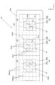
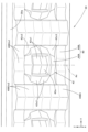
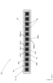
- a front view showing a vehicle lamp according to an embodiment of the present invention II-II cross-sectional view in Figure 1 A detailed view of part III in FIG. 1 showing a part of the light-transmitting member of the above-mentioned vehicle lamp together with a plurality of light emitting elements.
- a rear view showing a part of the above light-transmitting member Cross-sectional view taken along line V-V in Figure 3 A perspective view showing a part of the light-transmitting member as seen from diagonally above the front of the lamp.
- (a) is a diagram showing the operation of the above embodiment, and is a detailed view of the main part of FIG. 2, and
- (b) is a diagram similar to (a), showing a comparative example of the above embodiment.
- FIG. 1 is a front view showing a vehicle lamp 10 according to an embodiment of the present invention. Further, FIG. 2 is a sectional view taken along the line II-II in FIG. 1.
- the vehicle lamp 10 is a high-mounted stop lamp disposed at the rear of the vehicle, and includes a lamp body 12 and a transparent transparent lamp body 12 attached to the front end opening of the lamp body 12.
- a plurality of (specifically, 12) light emitting elements 20 and a light-transmitting member 30 are incorporated into the lamp chamber formed by the light cover 14.
- the plurality of light-emitting elements 20 are arranged at intervals from each other in the left-right direction (specifically, at equal intervals) with their light-emitting surfaces 20a facing toward the front of the lamp (specifically, toward the front of the lamp). There is.
- Each light emitting element 20 is a red light emitting diode, and its light emitting surface 20a has a rectangular outer shape (specifically, a square of about 1 ⁇ 1 mm).
- a plurality of light emitting elements 20 are mounted on a common substrate 22, and this substrate 22 is supported by the lamp body 12.
- the light-transmitting member 30 has a horizontally long rectangular outer shape when viewed from the front of the lamp, and is arranged on the front side of the lamp of the plurality of light emitting elements 20.
- a plurality of (specifically, 12) transmission control sections 40 for controlling transmission of light emitted from each of the plurality of light emitting elements 20 are arranged in a state in which they are lined up in the left-right direction.
- the structure is as follows.
- Each transmission control section 40 has a rectangular outer shape of the same size (specifically, a square of about 10 x 10 mm) when viewed from the front of the lamp.
- the light-transmitting member 30 is constructed as an injection molded product made of colorless and transparent synthetic resin (for example, acrylic resin).
- This light-transmitting member 30 has a flat plate-shaped outer peripheral flange portion 30a formed around the plurality of transmission control portions 40, and a rear surface of the outer peripheral flange portion 30a surrounding the plurality of transmission control portions 40.
- a frame portion 30b is formed so as to extend toward the rear of the lamp.
- the light-transmitting member 30 is supported by the lamp body 12 at its outer peripheral flange portion 30a and frame portion 30b.
- FIG. 3 is a detailed view of section III in FIG. 1 showing a part of the light-transmitting member 30 together with a plurality of light emitting elements 20.
- 4 is a rear view showing a portion of the light-transmitting member 30, and
- FIG. 5 is a sectional view taken along the line VV in FIG. 3.
- FIG. 6 is a perspective view of a portion of the light-transmitting member 30 as viewed diagonally from above and in front of the lamp.
- each transmission control section 40 has an optical axis Ax extending in the front-rear direction of the lamp.
- Each light emitting element 20 is arranged such that its light emission center (that is, the center position of the light emitting surface 20a) is located on the optical axis Ax of each transmission control section 40.
- Each transmission control section 40 includes a central region 40A located in front of the lamp of each light emitting element 20, and a peripheral region 40B located around this central region 40A.
- the central region 40A is configured as a lens section 42 that deflects and controls the light emitted from the light emitting element 20.
- the rear surface 42b of the lens portion 42 is formed to extend planarly along a vertical plane perpendicular to the optical axis Ax, and thereby refracts the light emitted from the light emitting element 20 toward the front of the lamp. It is composed of The rear surface 42b of this lens portion 42 has a circular outer shape centered on the optical axis Ax.
- the front surface 42a of the lens portion 42 has a square outer shape that is slightly larger than the rear surface 42b of the lens portion 42 when viewed from the front of the lamp. As a result, all of the light emitted from the light emitting element 20 that enters from the rear surface 42b of the lens portion 42 reaches the front surface 42a.
- the front surface 42a of the lens section 42 includes a plurality of lens elements 42s1, 42s2, and 42s3, each of which directs the light emitted from the light emitting element 20, which has entered from the rear surface 42b of the lens section 42, toward the front side of the lamp. It is configured to be refracted in the direction.
- the front surface 42a has a plurality of lenses divided into a plurality of segments divided by boundary lines extending in the left-right direction (i.e., a first direction) and the up-down direction (i.e., a second direction orthogonal to the first direction). It has a configuration in which elements 42s1, 42s2, and 42s3 are allocated.
- the plurality of lens elements 42s1, 42s2, and 42s3 include four lens elements 42s1 arranged around the optical axis Ax at the center of the front surface 42a, and 8 lens elements arranged on both left and right sides and upper and lower sides of the four lens elements 42s1. It is composed of one lens element 42s2 and four lens elements 42s3 arranged at four corners.
- the four lens elements 42s1 are all formed in a planar shape and have a substantially square outer shape when viewed from the front of the lamp. At this time, each lens element 42s1 is formed so as to extend in a direction that is inclined toward the rear side of the lamp as the distance from the optical axis Ax increases.
- the angle of inclination of each lens element 42s1 is set to a value such that the light emitted from the light emitting element 20 that enters from the rear surface 42b of the lens portion 42 is emitted toward the front of the lamp.
- the eight lens elements 42s2 are all formed in a planar shape and have an outer shape close to a square when viewed from the front of the lamp. At this time, each lens element 42s2 is formed to extend in a direction that is inclined toward the rear of the lamp as it becomes farther away from the optical axis Ax.
- the inclination angle of each lens element 42s2 is set to a value larger than the inclination angle of each lens element 42s1 so that the light emitted from the light emitting element 20 that enters from the rear surface 42b of the lens section 42 is emitted toward the front of the lamp. has been done.
- the four lens elements 42s3 are all formed in a concave curved shape and have an outer shape close to a square when viewed from the front of the lamp. At this time, the curvature of each lens element 42s3 is configured such that the light emitted from the light emitting element 20 that enters from the rear surface 42b of the lens portion 42 is emitted as diffused light toward the front of the lamp. .
- the peripheral area 40B of each transmission control section 40 includes an entrance surface 40B1 through which light emitted from the light emitting element 20 is incident, a total reflection surface 40B2 through which the light incident from this entrance surface 40B1 is totally reflected toward the front of the lamp, and It includes an output surface 40B3 that outputs the light totally reflected by the total reflection surface 40B2 toward the front of the lamp.
- the entrance surface 40B1 and the total reflection surface 40B2 of the peripheral region 40B are configured as a so-called Fresnel lens type total reflection prism.
- the entrance surface 40B1 and the total reflection surface 40B2 are composed of a plurality of entrance elements 40B1s and total reflection elements 40B2s separated by boundary lines extending concentrically around the optical axis Ax (that is, the axis extending in the longitudinal direction of the lamp). has been done.
- the light emitted from the light emission center of the light emitting element 22 is made incident in such a manner as to be refracted in a direction away from the optical axis Ax, and then directed toward the front of the lamp.
- the light is configured to be guided to the front surface 30a of the lens 30 as parallel light.
- the output surface 40B3 of the peripheral region 40B has a configuration in which a plurality of output elements 40B3s1 and 40B3s2 are allocated to a plurality of segments divided by boundary lines extending in the vertical and horizontal directions.
- the plurality of emitting elements 40B3s1 and 40B3s2 include six emitting elements 40B3s1 arranged side by side in the left-right direction on both upper and lower sides of the central region 40A, and on both left and right sides of the central region 40A and the six emitting elements 40B3s1. It is comprised of 12 output elements 40B3s2 arranged in a line in the vertical direction.
- the six output elements 40B3s1 are all formed in a concave curved shape toward the front of the lamp, and have a square outer shape when viewed from the front of the lamp. At this time, each output element 40B3s1 has its curvature so that the parallel light that has arrived from the plurality of input elements 40B1s and the total reflection element 40B2s is output as light that is somewhat diffused in the vertical and horizontal directions centering on the front direction of the lamp. is configured.
- Each of the twelve output elements 40B3s2 is formed into a concave curved surface that is inclined in the left-right direction from the front direction of the lamp in a direction closer to the optical axis Ax, and has a slightly oblong rectangular outer shape when viewed from the front of the lamp. are doing.
- each output element 40B3s2 outputs the parallel light that has arrived from the plurality of input elements 40B1s and the total reflection element 40B2s as light that is somewhat diffused around the front direction of the lamp in the vertical direction, and also outputs the parallel light that has arrived from the plurality of input elements 40B1s and the total reflection element 40B2s as light that is somewhat diffused with respect to the front direction of the lamp in the horizontal direction.
- the curvature is configured so that the light is emitted as light that is somewhat diffused in directions away from the front direction to both left and right sides.
- FIG. 7 is a front view showing the vehicle lamp 10 in a lit state.
- each of the plurality of transmission control sections 40 that constitute the light transmission member 30 appears to shine.
- each transmission control section 40 the central region 40A appears to shine at a plurality of locations, and the peripheral region 40B appears to shine at a plurality of locations.
- each transmission control section 40 is composed of a plurality of substantially rectangular lens elements 42s1, 42s2, and 42s3, each of them has a substantially rectangular shape. It looks like it's shining with its outline. The entire center region 40A also appears to shine with a substantially rectangular outline.
- each transmission control section 40 also has a light emitting surface 40B3 composed of a plurality of substantially rectangular light emitting elements 40B3s1 and 40B3s2, each of them appears to shine with a substantially rectangular outline.
- the peripheral region 40B as a whole also appears to shine with a substantially rectangular outline.
- the central region 40A is located close to the light emitting surface 20a of the light emitting element 20 and in a direction close to the direction perpendicular to the surface of the light emitting surface 20a, so that the emitted light from the light emitting element 20 enters efficiently. . Therefore, the central region 40A appears to shine brighter than the peripheral region 40B.
- the plurality of lens elements 42s1 and 42s2 located at the center of the central region 40A, above and below, and on both left and right sides direct the light emitted from the light emitting element 20, which has entered from the rear surface 42b of the lens portion 42, toward the front of the lamp. Since it is configured to emit light, it appears to shine brightly with a substantially rectangular outline larger than the lens elements 42s3 located at the four corners of the central region 40A and the plurality of emitting elements 40B3s1 and 40B3s2 located in the peripheral region 40B.
- the plurality of lens elements 42s3 located at the four corners of the central region 40A and the plurality of emission elements 40B3s1 and 40B3s2 located in the peripheral region 40B have a concave surface shape, so that they have a rectangular shape when viewed from the front of the lamp. It appears to be glowing in scattered spots along the outline of the .
- the optical function when the positional relationship between the plurality of light emitting elements 20 and the light-transmitting member 30 is shifted will be described.
- FIG. 8(a) is a detailed view of the main part of FIG. 2, and shows a case where the light emitting element 20 is displaced slightly upward from its original position (the position indicated by the two-dot chain line in the figure) with respect to the transmission control unit 40.
- the optical path of light emitted from the light emitting center of the light emitting element 20 is shown in FIG.
- the optical path shown by the two-dot chain line in FIG. 8(a) is the optical path of the light emitted from the light emission center of the light emitting element 20 at the original position.
- the optical path shown by the solid line in FIG. 8A the light emitted from the light emission center of the light emitting element 20 that has been displaced somewhat upward from its original position (hereinafter simply referred to as "displaced upward") is transmitted to the transmission control unit 40. This is the optical path when the light is incident on the same position as the light beam.
- the light emitted from the light emitting element 20 displaced upward enters the central region 40A of the transmission control section 40 at the same position as the light emitted from the light emitting element 20 in its original position.
- the light emitted from the light emitting element 20 at its original position is deflected downward at the rear surface 42b of the lens section 42, and when the light is emitted from the central region 40A, the light is deflected downward from the original position at the front surface 42a of the lens section 42.
- the light emitted from the light emitting element 20 at the position is deflected downward.
- the downward deflection angle ⁇ 1 of the emitted light from the lens element 42s1 closer to the optical axis Ax becomes a value larger than the downward deflection angle ⁇ 2 of the emitted light from the lens element 42s2 located at a position away from the optical axis Ax.
- the light emitted from the light emitting element 20 displaced upward enters the peripheral region 40B, the light emitted from the light emitting element 20 at the original position is deflected downward in the incident element 40B1s, but after that, the light emitted from the light emitting element 20 displaced upward is deflected downward.
- the reflective element 40B2s By being totally reflected by the reflective element 40B2s, the light is deflected upward compared to the light emitted from the light emitting element 20 at the original position.
- the light emitted from the peripheral region 40B is emitted from the transmission control unit 40 as light that is polarized in the opposite direction from the light emitted from the central region 40A.
- the upward deflection angle ⁇ 3 of the emitted light from the output element 40B3s1 has a smaller value than the downward deflection angles ⁇ 1 and ⁇ 2.
- FIG. 8(b) is a diagram similar to FIG. 8(a), showing a light-transmitting member 30' according to a comparative example of the present embodiment.
- the basic configuration of the light transmitting member 30' according to this comparative example is the same as that of the present embodiment, but the configuration of each transmission control section 40' is different from that of the present embodiment. The case is partially different.
- the transmission control section 40' of this comparative example also has the same peripheral region 40B as the transmission control section 40 of this embodiment, but the configuration of the central region 40A' is different from that of this embodiment. .
- the central region 40A' is configured as a lens section 42', but the rear surface 40b' is formed in a convex spherical shape centered on the optical axis Ax.
- the transmission control section 40' of this comparative example is configured to refract the light emitted from the light emitting element 20 more at the rear surface 40b' of the lens section 42' than in the present embodiment.
- the front surface 42a' of this lens portion 42' has a configuration in which a plurality of lens elements 42s1' and 42s2' are allocated to a plurality of segments divided by boundary lines extending in the vertical and horizontal directions.
- These plurality of lens elements 42s1' and 42s2' are all formed in a planar shape and have a substantially square outer shape when viewed from the front of the lamp. is formed to extend along a vertical plane perpendicular to the optical axis Ax.
- the light emitted from the light emission center of the light emitting element 20 in the original position is made to enter the lens part 42' as parallel light heading toward the front of the lamp from the rear surface 40b' of the lens part 42'.
- the plurality of lens elements 42s1' and 42s2' formed on the front surface 42a' of the lamp 42' emit parallel light directly toward the front of the lamp.
- the light emitted from the upwardly displaced light emitting element 20 is located at the same position as the light emitted from the light emitting element 20 at its original position in the central region 40A' of the transmission control section 40'.
- the light enters the lens portion 42' the light is deflected downward at the rear surface 42b' of the lens portion 42' than the light emitted from the light emitting element 20 at the original position, and when the light exits from the central region 40A', the lens portion 42' At the front surface 42a' of ', the light is deflected downward from the light emitted from the light emitting element 20 at the original position.
- the central region 40A' of the transmission control section 40' refracts the emitted light from the light emitting element 20 more at the rear surface 42b' of the lens section 42' than in the present embodiment, so that the central region 40A' The emitted light is deflected downward to a greater extent than in the present embodiment. That is, the downward deflection angles ⁇ 1' and ⁇ 2' of the emitted light from each lens element 42s1' and 42s2' are larger than the downward deflection angles ⁇ 1 and ⁇ 2 of the emitted light from each lens element 42s1 and 42s2 of this embodiment. becomes.
- the configuration of the peripheral area 40B of the transmission control unit 40' of this comparative example is the same as that of the present embodiment, so that the emitted light from the upwardly displaced light emitting element 20 is transmitted from the output element 40B3s1 of the peripheral area 40B.
- the light is deflected upward compared to the light emitted from the light emitting element 20 in its original position, and the upward deflection angle ⁇ 3 at that time is the same as in the present embodiment.
- the transmission control section 40' of this comparative example converts the light emitted from the light emission center of the light emitting element 20 into parallel light directed toward the front direction of the lamp at the rear surface 40b' of the lens section 42' that constitutes the central region 40A'. Since the light emitting element 20 is configured to be incident, if the positional relationship between the light emitting element 20 and the transmission control section 40' shifts, the direction of the emitted light from the central region 40A' will shift significantly. As a result, the state in which each of the plurality of lens elements 42s1' and 42s2' appears brightly emitted while being divided into substantially rectangular shapes changes greatly.
- the lens section 42 constituting the central region 40A refracts the light emitted from the light emission center of the light emitting element 20 in two stages at the rear surface 40b and the front surface 40a. Since the parallel light is directed toward the front of the lamp, even if the positional relationship between the light emitting element 20 and the transmission control section 40 shifts, the direction of the light emitted from the central region 40A will not shift significantly. do not have. As a result, the state in which each of the plurality of lens elements 42s1 and 42s2 appears to emit bright light while being divided into substantially rectangular shapes does not change significantly.
- the light emitted from the peripheral region 40B is shifted in the opposite direction from the light emitted from the center region 40A.
- the vehicle lamp 10 includes a light-transmitting member 30 that extends in the left-right direction (first direction) to emit light from a plurality of light-emitting elements 20 arranged with the light-emitting surfaces 20a facing forward.
- Transmission control is performed by a plurality of transmission control sections 40, each of which includes a central region 40A located in front of the lamp of each light emitting element 20 and a peripheral region 40B located around the central region 40A. Therefore, by lighting the plurality of light emitting elements 20, each of the plurality of transmission control sections 40 can be made to appear to shine in each of its central region 40A and peripheral region 40B.
- each transmission control section 40 is configured as a lens section 42 that deflects and controls the emitted light from each light emitting element 20, and the rear surface 42b of this lens section 42 is configured to deflect the emitted light from each light emitting element 20.
- a plurality of lens elements 42s1, 42s2, and 42s3 are formed on the front surface 42a of the lens section 42, and each of them is configured to refract the light toward the front of the lamp. Since the light emitted from the light emitting element 20 entering from the rear surface 42b is refracted toward the front of the lamp, the following effects can be obtained.
- each light emitting element 20 since the emitted light from each light emitting element 20 efficiently enters the central region 40A of each transmission control section 40, the plurality of lens elements 42s1 formed on the front surface 42a of the lens section 42 constituting this central region 40A , 42s2, and 42s3 each appear to emit bright light.
- each transmission control section 40 is configured to refract the light emitted from each light emitting element 20 in two stages at the rear surface 42b and the front surface 42a, so that a plurality of light emitting elements can be refracted. Even if the positional relationship between the element 20 and the light-transmitting member 30 is slightly shifted, the state in which each of the plurality of lens elements 42s1, 42s2, and 42s3 appears to emit bright light does not change significantly. This allows the appearance of the light-transmitting member 30 to be maintained.
- the vehicle lamp 10 configured to transmit and control the transmission of light emitted from the plurality of light emitting elements 20 by the light transmitting member 30, the plurality of light emitting elements 20 and the light transmitting member 30 are connected to each other.
- the appearance of the light-transmitting member 30 can be improved even if the positional relationship between the two is slightly shifted.
- the plurality of lens elements 42s1, 42s2, and 42s3 are allocated to a plurality of segments divided by boundary lines extending in the vertical direction (second direction perpendicular to the first direction) and horizontal direction.
- each of the plurality of lens elements 42s1, 42s2, and 42s3 has a substantially rectangular outer shape, when the light-transmitting member 30 is observed from the front of the lamp with the plurality of light-emitting elements 20 turned on, In each of the plurality of transmission control sections 40 arranged in a row in the left-right direction, the central region 40A can be made to appear brightly emitted while being divided into approximately rectangular shapes, thereby allowing the transmission of light. The appearance of the member 30 can be improved.
- the plurality of lens elements 42s1, 42s2, and 42s3 located in the central region 40A are Since the light emitted from the light emitting element 20 entering from the rear surface 42b is configured to be emitted toward the front of the lamp, the main part of the central region 40A of each transmission control section 40 has a substantially rectangular shape when viewed from the front of the lamp. It is possible to make the lights appear to emit bright light all at once, even though they are divided into sections.
- the peripheral region 40B of each transmission control section 40 has an entrance surface 40B1 through which the light emitted from the light emitting element 20 enters, and a light incident from this entrance surface 40B1 toward the front of the lamp.
- the light emitting element 20 is provided with a total reflection surface 40B2 that completely reflects the light towards the lamp, and an output surface 40B3 that emits the light totally reflected by the total reflection surface 40B2 toward the front of the lamp. It can be used as irradiation light.
- the central region 40A of each transmission control section 40 but also the peripheral region 40B can be made to emit light with a certain level of brightness and appear visible.
- the output surface 40B3 of the peripheral area 40B is composed of a plurality of output elements 40B3s1 and 40B3s2 divided by boundary lines extending in the vertical direction and the horizontal direction, only the central area 40A of each transmission control section 40 can be used.
- the peripheral region 40B can also be made to emit light and appear to be divided into approximately rectangular shapes, thereby further improving the appearance of the light-transmitting member 30.
- the incident surface 40B1 and the total reflection surface 40B2 of the peripheral region 40B are defined by boundary lines that extend concentrically around the optical axis Ax (an axis extending in the front-rear direction of the lamp). Since the reflective element 40B2s is divided, the light emitted from the light emitting element 20 can be used as forward illumination light over a wide range while making the light transmitting member 30 thinner.
- the plurality of lens elements 42s1, 42s2, and 42s3 constituting the front surface 42a of the lens section 42 have been described as having mutually different external shapes, but the lens elements 42s1, 42s2, and 42s3 of the same size are divided into vertical and horizontal grids. A configuration having a rectangular outer shape is also possible.
- each of the plurality of lens elements 42s1, 42s2, and 42s3 has been described as having a substantially rectangular outer shape, but the outer shape may have an outer shape other than this (for example, a triangle or a hexagon). It is also possible to have a configuration having a shape.
- the configuration of the peripheral region 44 of each transmission control section 40 is such that the entrance surface 40B1 and the total reflection surface 40B2 of the peripheral region 40B are divided into a plurality of entrance elements 40B1s and total reflection elements 40B2s.
- the plurality of output elements 40B3s1 and 40B3s2 constituting the output surface 40B3 of the peripheral region 44 have been described as having mutually different external shapes.
- the light-transmitting member 30 has been described as having an outer shape of a horizontally long rectangle when viewed from the front of the lamp. It is also possible to have a configuration having a shape, etc.).
- the light transmitting member 30 has been described as having a plurality of transmission control units 40 arranged in a line in the left and right direction, but it is also possible to have a configuration in which these are arranged in multiple stages above and below. .
- the configuration of the vehicle lamp 10 is described as one in which a plurality of light emitting elements 20 and a light transmitting member 30 are incorporated in a lamp chamber formed by a lamp body 12 and a light transmitting cover 14.
- a high-mounted stop lamp or the like disposed at the rear of the vehicle interior, it is also possible to configure the light-transmitting cover 14 not to exist.
- the vehicle lamp 10 is a high-mounted stop lamp disposed at the rear of the vehicle, but the same configuration as in the above embodiment may be adopted regardless of the location or function provided in the vehicle. By doing so, the same effects as those of the above embodiment can be obtained. That is, in addition to the high-mounted stop lamp, for example, tail and stop lamps, rear fog lamps, daytime running lamps, clearance lamps, etc. can be employed. In this case, in addition to red light emitting diodes, white or amber light emitting diodes can be used as the plurality of light emitting elements 20 depending on the function of each lamp.
- FIG. 9 is a diagram similar to FIG. 5, showing the main parts of the vehicle lamp according to this modification.
- the basic configuration of this modification is the same as that of the above embodiment, but the configuration of the light-transmitting member 130 is partially different from that of this embodiment.
- the light-transmitting member 130 of this modification also has a configuration in which a plurality of transmission control sections 140 are arranged side by side in the left-right direction, and each transmission control section 140 is the same as the transmission control section 40 of this embodiment. Although it has a similar peripheral region 40B, the configuration of its central region 140A is different from that of the above embodiment.
- each transmission control section 140 is configured as a lens section 142, but each of the plurality of lens elements 142s1 and 142s2 constituting the front surface 142a is It differs from the above embodiment in that it is formed in a concave curved shape.
- the configuration of the rear surface 142b of the lens portion 142 is the same as in the above embodiment.
- the lens portion 142 constituting the central region 140A of each transmission control portion 140 controls the emitted light from each light-emitting element 20 in two stages on the rear surface 142b and the front surface 142a.
- the structure is such that the beam is refracted.
- each of the plurality of lens elements 142s1 and 142s2 is formed in a concave curved shape, the light emitted from the light emitting element 20 that enters from the rear surface 142b of the lens portion 142 is a diffused light centered in the front direction of the lamp. The light is emitted from each lens element 142s1, 142s2.
- the light-transmitting member 130 of this modification not only appears to emit bright light with the main part of the central region 40A of each transmission control section 40 divided into approximately rectangular shapes when viewed from the front of the lamp; Even if the viewpoint is moved a little from this state, it is possible to maintain the state in which the main part of the central region 40A of each transmission control section 40 appears to be divided into substantially rectangular shapes and emit bright light.
- FIG. 10 is a diagram similar to FIG. 5, showing the main parts of the vehicle lamp according to this modification.
- the basic configuration of this modification is the same as that of the above embodiment, but the configuration of the light-transmitting member 230 is partially different from that of this embodiment.
- the light-transmitting member 230 of this modification also has a configuration in which a plurality of transmission control sections 240 are arranged side by side in the left-right direction, and each transmission control section 240 is the same as the transmission control section 40 of this embodiment. Although it has a similar peripheral region 40B, the configuration of its central region 240A is different from that of the above embodiment.
- each transmission control section 240 is configured as a lens section 242, but the inner region of each of the plurality of lens elements 242s2 forming the front surface 242a is The shape of the peripheral region (that is, the region closer to the optical axis Ax) 242s2a is partially different from that of the above embodiment. That is, each lens element 242s2 is formed such that its inner peripheral edge region 242s2a extends in a direction that is inclined toward the front side of the lamp as the distance from the optical axis Ax increases.
- the arrangement of the plurality of lens elements 242s1 and the external shape of each of them are the same as in the above embodiment, and the general area other than the inner peripheral edge area 242s2a of each of the plurality of lens elements 242s2 is The configuration is the same as in the above embodiment.
- the configuration of the rear surface 242b of the lens portion 242 is the same as in the above embodiment.
- the transmission control section 240 of the present modification the light emitted from the light emitting element 20 that enters from the rear surface 242b of the lens section 242 and reaches each of the plurality of lens elements 242s2 is not transmitted to the lamp in its general area.
- the light is emitted toward the front, and in the inner circumferential edge region 242s2a, the light is emitted in a direction inclined outward from the front direction of the lamp.
- the light-transmitting member 230 of this modification maintains a state where the main part of the center region 40A of each transmission control section 40 appears to emit bright light all at once in a state where the main part of the central region 40A of each transmission control section 40 is divided into approximately rectangular shapes when viewed from the front of the lamp. Even when the viewpoint is greatly moved from the state in which the lamp is viewed from the front, it is possible to produce a state in which the inner circumferential edge region 242s2a of some of the lens elements 242s2 appears to emit bright light.
- Vehicle lamp 12 Lamp body 14 Light-transmitting cover 20 Light-emitting element 20a Light-emitting surface 22 Substrate 30, 130, 230 Light-transmitting member 30a Outer flange portion 30b Frame portion 40, 140, 240 Transmission control portion 40A, 140A, 240A Center region 40B Peripheral area 40B1 Incident surface 40B1s Incident element 40B2 Total reflection surface 40B2s Total reflection element 40B3 Output surface 40B3s1, 40B3s2 Output element 42, 142, 242 Lens section 42a, 142a, 242a Front surface 42b, 142b, 242b Rear surface 42s 1, 42s2, 42s3, 142s1 , 142s2, 242s1, 242s2 Lens element 242s2a Inner peripheral area Ax Optical axis
Landscapes
- Engineering & Computer Science (AREA)
- General Engineering & Computer Science (AREA)
- Non-Portable Lighting Devices Or Systems Thereof (AREA)
Abstract
複数の発光素子からの出射光を透光部材によって透過制御するように構成された車両用灯具において、複数の発光素子と透光部材との位置関係が多少ずれていても透光部材の見映え向上を図る。透光部材(30)として、複数の透過制御部(40)が左右方向に並んだ状態で配置された構成とし、その各々の中心領域(40A)をレンズ部(42)として構成する。そして、レンズ部(42)の後面(42b)および前面(42a)において発光素子(20)からの出射光を2段階で屈折させ、灯具正面方向へ向けて出射させる構成とする。その際、レンズ部(42)の前面(42a)に、略矩形状の外形形状を有する複数のレンズ素子(42s1、42s2、42s3)を形成する。これにより、複数の発光素子(20)を点灯させた状態で透光部材(30)を灯具前方から観察したとき、複数の透過制御部(40)の各々において、その中心領域(40A)が略矩形状に区分けされた状態で明るく発光して見えるようにする
Description
本願発明は、複数の発光素子と透光部材とを備えた車両用灯具に関するものである。
従来より、複数の発光素子からの出射光を透光部材によって透過制御するように構成された車両用灯具として、発光面を灯具前方へ向けた状態で配置された複数の発光素子の灯具前方側に、複数の透過制御部を備えた透光部材が配置されたものが知られている。
「特許文献1」や「特許文献2」には、このような車両用灯具の構成として、複数の発光素子が灯具前後方向と交差する第1の方向に互いに間隔をおいて配置されるとともに、複数の透過制御部が上記第1の方向に並んだ状態で配置されたものが記載されている。
その際、各透過制御部は各発光素子の灯具前方に位置する中心領域とその周囲に位置する周辺領域とを備えた構成となっており、その中心領域は発光素子からの出射光を偏向制御するレンズ部として構成されている。また、各発光素子は各透過制御部の中心領域に近接した状態で配置されている。
このような車両用灯具の透光部材においては、各透過制御部の中心領域に対して各発光素子からの出射光が効率良く入射するので、この中心領域が明るく発光して見える。
しかしながら、このような車両用灯具において、複数の発光素子と透光部材との位置関係が本来の状態からずれてしまうと、各透過制御部において明るく発光して見えるはずの中心領域の発光の仕方が大きく変化してしまい、このため透光部材の見映え向上を図ることができなくなってしまう。
本願発明は、このような事情に鑑みてなされたものであって、複数の発光素子からの出射光を透光部材によって透過制御するように構成された車両用灯具において、複数の発光素子と透光部材との位置関係が多少ずれていても透光部材の見映え向上を図ることができる車両用灯具を提供することを目的とするものである。
本願発明は、透光部材の構成に工夫を施すことにより、上記目的達成を図るようにしたものである。
すなわち、本願発明に係る車両用灯具は、
複数の発光素子と、上記複数の発光素子の灯具前方側に配置された透光部材と、を備えた車両用灯具において、
上記複数の発光素子は、発光面を灯具前方へ向けた状態で灯具前後方向と交差する第1の方向に互いに間隔をおいて配置されており、
上記透光部材は、上記複数の発光素子の各々からの出射光を透過制御するための複数の透過制御部を備えており、
上記複数の透過制御部は、上記第1の方向に並んだ状態で配置されており、
上記各透過制御部は、上記各発光素子の灯具前方に位置する中心領域と、上記中心領域の周囲に位置する周辺領域とを備えており、
上記中心領域は、上記発光素子からの出射光を偏向制御するレンズ部として構成されており、
上記レンズ部の後面は、上記発光素子からの出射光を灯具正面方向寄りの方向へ屈折させるように構成されており、
上記レンズ部の前面に、複数のレンズ素子が形成されており、
上記複数のレンズ素子の各々は、上記レンズ部の後面から入射した上記発光素子からの出射光の少なくとも一部を灯具正面方向寄りの方向へ屈折させるように構成されている、ことを特徴とするものである。
複数の発光素子と、上記複数の発光素子の灯具前方側に配置された透光部材と、を備えた車両用灯具において、
上記複数の発光素子は、発光面を灯具前方へ向けた状態で灯具前後方向と交差する第1の方向に互いに間隔をおいて配置されており、
上記透光部材は、上記複数の発光素子の各々からの出射光を透過制御するための複数の透過制御部を備えており、
上記複数の透過制御部は、上記第1の方向に並んだ状態で配置されており、
上記各透過制御部は、上記各発光素子の灯具前方に位置する中心領域と、上記中心領域の周囲に位置する周辺領域とを備えており、
上記中心領域は、上記発光素子からの出射光を偏向制御するレンズ部として構成されており、
上記レンズ部の後面は、上記発光素子からの出射光を灯具正面方向寄りの方向へ屈折させるように構成されており、
上記レンズ部の前面に、複数のレンズ素子が形成されており、
上記複数のレンズ素子の各々は、上記レンズ部の後面から入射した上記発光素子からの出射光の少なくとも一部を灯具正面方向寄りの方向へ屈折させるように構成されている、ことを特徴とするものである。
上記「車両用灯具」の種類は特に限定されるものではなく、例えばハイマウントストップランプ、デイタイムランニングランプ、ウェルカムランプあるいは自動運転状態や充電状態の表示を行うインジケータランプ等が採用可能である。
上記「発光素子」の種類は特に限定されるものではなく、例えば発光ダイオードやレーザダイオード等が採用可能である。
上記「発光素子」は、発光面を灯具前方へ向けた状態で配置されていれば、必ずしも灯具正面方向へ向けた状態で配置されていなくてもよい。
上記「中心領域」および「周辺領域」の各々の具体的な範囲は特に限定されるものではない。
上記「レンズ部の後面」は、発光素子からの出射光を灯具正面方向寄りの方向へ屈折させるように構成されていれば、その具体的な屈折角度は特に限定されるものではない。
上記「複数のレンズ素子」は、同一の形状で形成されていてもよいし、互いに異なる形状で形成されていてもよい。
上記「複数のレンズ素子の各々」は、レンズ部の後面から入射した発光素子からの出射光の少なくとも一部を灯具正面方向寄りの方向へ屈折させるように構成されていれば、その具体的な屈折角度は特に限定されるものではない。
本願発明に係る車両用灯具は、発光面を灯具前方へ向けて配置された複数の発光素子からの出射光を、第1の方向に延びる透光部材を構成する複数の透過制御部によって透過制御する構成となっているが、各透過制御部は各発光素子の灯具前方に位置する中心領域とその周囲に位置する周辺領域とを備えているので、複数の発光素子の点灯によって複数の透過制御部の各々がその中心領域および周辺領域毎に光って見えるようにすることができる。
その際、各透過制御部の中心領域は各発光素子からの出射光を偏向制御するレンズ部として構成されているが、このレンズ部の後面は発光素子からの出射光を灯具正面方向寄りの方向へ屈折させるように構成されており、また、このレンズ部の前面には複数のレンズ素子が形成されており、その各々がレンズ部の後面から入射した発光素子からの出射光の少なくとも一部を灯具正面方向寄りの方向へ屈折させる構成となっているので、次のような作用効果を得ることができる。
すなわち、各透過制御部の中心領域には各発光素子からの出射光が効率良く入射するので、この中心領域を構成するレンズ部の前面に形成された複数のレンズ素子はその各々が明るく発光して見える。
しかも、各透過制御部の中心領域を構成するレンズ部は、その後面および前面において各発光素子からの出射光を2段階で屈折させる構成となっているので、複数の発光素子と透光部材との位置関係が多少ずれたような場合であっても、複数のレンズ素子の各々が明るく発光して見える状態が大きく変化してしまわないようにすることができ、これにより透光部材の見映えが維持されるようにすることができる。
このように本願発明によれば、複数の発光素子からの出射光を透光部材によって透過制御するように構成された車両用灯具において、複数の発光素子と透光部材との位置関係が多少ずれていても透光部材の見映え向上を図ることができる。
上記構成において、さらに、複数のレンズ素子が、上記第1の方向およびこれと直交する第2の方向に延びる境界線によって区分けされた複数のセグメントに割り付けられた構成とすれば、次のような作用効果を得ることができる。
すなわち、複数のレンズ素子の各々は略矩形状の外形形状を有するものとなるので、複数の発光素子を点灯させた状態で透光部材を灯具前方から観察したとき、上記第1の方向に並んだ状態で配置された複数の透過制御部の各々において、その中心領域が略矩形状に区分けされた状態で明るく発光して見えるようにすることができ、これにより透光部材の見映え向上を図ることができる。
上記構成において、さらに、複数のレンズ素子の各々の構成として、レンズ部の後面から入射した発光素子からの出射光を灯具正面方向へ向けて出射させるように構成されたものとすれば、灯具正面視において各透過制御部の中心領域が一斉に明るく発光して見えるようにすることができる。
上記構成において、さらに、各透過制御部の周辺領域の構成として、発光素子からの出射光を入射させる入射面と、この入射面から入射した光を灯具前方へ向けて全反射させる全反射面と、この全反射面で全反射した光を灯具前方へ向けて出射させる出射面とを備えたものとすれば、光源からの出射光を広範囲にわたって前方照射光として利用することができる。そしてこれにより、各透過制御部の中心領域のみならず周辺領域についても一定程度の明るさで発光して見えるようにすることができる。
その際、周辺領域の出射面が、第1および第2の方向に延びる境界線によって区分けされた複数の出射素子で構成されたものとすれば、各透過制御部の中心領域のみならず周辺領域についても略矩形状に区分けされた状態で発光して見えるようにすることができ、これにより透光部材のさらなる見映え向上を図ることができる。
また、その際、周辺領域の入射面および全反射面が、灯具前後方向に延びる軸線を中心にして同心円状に延びる境界線によって複数の入射素子および全反射素子に区分けされた構成とすれば、透光部材の薄型化を図った上で、発光素子からの出射光を広範囲にわたって前方照射光として利用することができる。
以下、図面を用いて、本願発明の実施の形態について説明する。
図1は、本願発明の一実施形態に係る車両用灯具10を示す正面図である。また、図2は、図1のII-II線断面図である。
図1、2において、Xで示す方向が「灯具前方」(車両としては「後方」)であり、Yで示す方向が「灯具前方」と直交する「右方向」(車両としても「右方向」)であり、Zで示す方向が「上方向」である。なお、図1、2以外の図においても同様である。
図1、2に示すように、本実施形態に係る車両用灯具10は、車両後部に配置されるハイマウントストップランプであって、ランプボディ12とその前端開口部に取り付けられた素通し状の透光カバー14とで形成される灯室内に、複数の(具体的には12個の)発光素子20と透光部材30とが組み込まれた構成となっている。
複数の発光素子20は、その発光面20aを灯具前方(具体的には灯具正面方向)へ向けた状態で左右方向に互いに間隔をおいて(具体的には等間隔をおいて)配置されている。各発光素子20は赤色発光ダイオードであって、その発光面20aは矩形状(具体的には1×1mm程度の正方形)の外形形状を有している。
複数の発光素子20は共通の基板22に搭載されており、この基板22はランプボディ12に支持されている。
透光部材30は、灯具正面視において横長矩形状の外形形状を有しており、複数の発光素子20の灯具前方側に配置されている。この透光部材30は、複数の発光素子20の各々からの出射光を透過制御するための複数の(具体的には12個の)透過制御部40が左右方向に並んだ状態で配置された構成となっている。各透過制御部40は、灯具正面視において同一サイズの矩形状(具体的には10×10mm程度の正方形)の外形形状を有している。
透光部材30は、無色透明の合成樹脂製(例えばアクリル樹脂製)の射出成形品として構成されている。この透光部材30には、複数の透過制御部40の周囲に平板状の外周フランジ部30aが形成されており、また、この外周フランジ部30aの後面には、複数の透過制御部40を囲むようにして灯具後方へ向けて延びるフレーム部30bが形成されている。そして、この透光部材30は、その外周フランジ部30aおよびフレーム部30bにおいてランプボディ12に支持されている。
図3は、透光部材30の一部分を複数の発光素子20と共に示す、図1のIII部詳細図である。また、図4は透光部材30の一部分を示す背面図であり、図5は図3のV-V線断面図である。さらに、図6は透光部材30の一部分を灯具前方斜め上方から見て示す斜視図である。
図3~6にも示すように、各透過制御部40は、灯具前後方向に延びる光軸Axを有している。そして各発光素子20は、その発光中心(すなわち発光面20aの中心位置)が各透過制御部40の光軸Ax上に位置する状態で配置されている。
各透過制御部40は、各発光素子20の灯具前方に位置する中心領域40Aと、この中心領域40Aの周囲に位置する周辺領域40Bとを備えている。
中心領域40Aは、発光素子20からの出射光を偏向制御するレンズ部42として構成されている。
レンズ部42の後面42bは、光軸Axと直交する鉛直面に沿って平面状に延びるように形成されており、これにより発光素子20からの出射光を灯具正面方向寄りの方向へ屈折させるように構成されている。このレンズ部42の後面42bは、光軸Axを中心とする円形の外形形状を有している。
レンズ部42の前面42aは、灯具正面視においてレンズ部42の後面42b外形形状よりもひと回り大きい正方形の外形形状を有している。そしてこれにより、レンズ部42の後面42bから入射した発光素子20からの出射光が全て前面42aに到達するように構成されている。
すなわち、レンズ部42の前面42aは、複数のレンズ素子42s1、42s2、42s3を備えており、その各々において、レンズ部42の後面42bから入射した発光素子20からの出射光を灯具正面方向寄りの方向へ屈折させるように構成されている。その際、この前面42aは、左右方向(すなわち第1の方向)および上下方向(すなわち第1の方向と直交する第2の方向)に延びる境界線によって区分けされた複数のセグメントに、複数のレンズ素子42s1、42s2、42s3が割り付けられた構成となっている。
具体的には、複数のレンズ素子42s1、42s2、42s3は、前面42aの中央部において光軸Axを中心にして配置された4つのレンズ素子42s1と、その左右両側および上下両側に配置された8つのレンズ素子42s2と、4箇所のコーナー部に配置された4つのレンズ素子42s3とで構成されている。
4つのレンズ素子42s1は、いずれも平面状に形成されており、灯具正面視において略正方形の外形形状を有している。その際、各レンズ素子42s1は、光軸Axから離れるに従って灯具後方側へ傾斜する方向に延びるように形成されている。各レンズ素子42s1の傾斜角度は、レンズ部42の後面42bから入射した発光素子20からの出射光が灯具正面方向へ向けて出射するような値に設定されている。
8つのレンズ素子42s2は、いずれも平面状に形成されており、灯具正面視において正方形に近い外形形状を有している。その際、各レンズ素子42s2は、光軸Axから離れるに従って灯具後方側へ傾斜する方向に延びるように形成されている。各レンズ素子42s2の傾斜角度は、レンズ部42の後面42bから入射した発光素子20からの出射光が灯具正面方向へ向けて出射するように、各レンズ素子42s1の傾斜角度よりも大きい値に設定されている。
4つのレンズ素子42s3は、いずれも凹曲面状に形成されており、灯具正面視において正方形に近い外形形状を有している。その際、各レンズ素子42s3は、レンズ部42の後面42bから入射した発光素子20からの出射光が灯具正面方向寄りの方向へ向けて拡散光として出射するように、その曲率が構成されている。
各透過制御部40の周辺領域40Bは、発光素子20からの出射光を入射させる入射面40B1と、この入射面40B1から入射した光を灯具前方へ向けて全反射させる全反射面40B2と、この全反射面40B2で全反射した光を灯具前方へ向けて出射させる出射面40B3とを備えている。
周辺領域40Bの入射面40B1および全反射面40B2は、いわゆるフレネルレンズ型全反射プリズムとして構成されている。
すなわち、入射面40B1および全反射面40B2は、光軸Ax(すなわち灯具前後方向に延びる軸線)を中心にして同心円状に延びる境界線によって区分けされた複数の入射素子40B1sおよび全反射素子40B2sで構成されている。
そして、これら複数の入射素子40B1sおよび全反射素子40B2sの各々において、発光素子22の発光中心からの出射光を、光軸Axから離れる方向へ屈折させる態様で入射させた後、灯具正面方向へ向かう平行光としてレンズ30の前面30aに導くように構成されている。
周辺領域40Bの出射面40B3は、上下方向および左右方向に延びる境界線によって区分けされた複数のセグメントに複数の出射素子40B3s1、40B3s2が割り付けられた構成となっている。
具体的には、複数の出射素子40B3s1、40B3s2は、中心領域40Aの上下両側において左右方向に並んで配置された6つの出射素子40B3s1と、これら中心領域40Aおよび6つの出射素子40B3s1の左右両側において上下方向に並んで配置された12個の出射素子40B3s2とで構成されている。
6つの出射素子40B3s1は、いずれも灯具正面方向へ向けて凹曲面状に形成されており、灯具正面視において正方形の外形形状を有している。その際、各出射素子40B3s1は、複数の入射素子40B1sおよび全反射素子40B2sから到達した平行光を、灯具正面方向を中心にして上下および左右方向に多少拡散する光として出射させるように、その曲率が構成されている。
12個の出射素子40B3s2は、いずれも左右方向に関して灯具正面方向から光軸Ax寄りの方向に傾斜した状態で凹曲面状に形成されており、灯具正面視においてやや横長矩形状の外形形状を有している。その際、各出射素子40B3s2は、複数の入射素子40B1sおよび全反射素子40B2sから到達した平行光を、上下方向に関しては灯具正面方向を中心にして多少拡散する光として出射させるとともに左右方向に関しては灯具正面方向から左右両側へ離れる方向にかけて多少拡散する光として出射させるように、その曲率が構成されている。
図7は、車両用灯具10を点灯状態で示す正面図である。
図7に示すように、複数の発光素子20が同時に点灯すると、透光部材30を構成する複数の透過制御部40の各々が光って見える。
すなわち、各透過制御部40は、中心領域40Aが複数箇所において光って見えるとともに周辺領域40Bが複数箇所において光って見える。
その際、各透過制御部40の中心領域40Aを構成するレンズ部42は、その前面42aが複数の略矩形状のレンズ素子42s1、42s2、42s3で構成されているので、その各々が略矩形状の輪郭で光って見える。そして、中心領域40A全体としても略矩形状の輪郭で光って見える。
また、各透過制御部40の周辺領域40Bも、その出射面40B3が複数の略矩形状の出射素子40B3s1、40B3s2で構成されているので、その各々が略矩形状の輪郭で光って見える。そして、周辺領域40B全体としても略矩形状の輪郭で光って見える。
各透過制御部40において、中心領域40Aは発光素子20の発光面20aに近くかつ発光面20aの面直方向に近い方向に位置しているので、発光素子20からの出射光が効率良く入射する。このため中心領域40Aは周辺領域40Bよりも明るく光って見える。
その際、中心領域40Aの中央部およびその上下および左右両側に位置する複数のレンズ素子42s1、42s2は、レンズ部42の後面42bから入射した発光素子20からの出射光を灯具正面方向へ向けて出射させるように構成されているので、中心領域40Aの四隅に位置するレンズ素子42s3や周辺領域40Bに位置する複数の出射素子40B3s1、40B3s2よりも大きな略矩形状の輪郭で明るく光って見える。
一方、中心領域40Aの四隅に位置する複数のレンズ素子42s3および周辺領域40Bに位置する複数の出射素子40B3s1、40B3s2は、凹曲面状の表面形状を有しているので、灯具正面視において矩形状の輪郭で散点的に光って見える。
次に、本実施形態に係る車両用灯具10において、複数の発光素子20と透光部材30との位置関係がずれてしまった場合の光学的機能について説明する。
図8(a)は、図2の要部詳細図であって、発光素子20が透過制御部40に対して本来の位置(図中2点鎖線で示す位置)から多少上方側に変位した場合における、発光素子20の発光中心からの出射光の光路を示している。
図8(a)において2点鎖線で示す光路は、本来の位置にある発光素子20の発光中心からの出射光の光路である。一方、図8(a)において実線で示す光路は、本来の位置から多少上方側に変位した(以下単に「上方変位した」という)発光素子20の発光中心からの出射光が、透過制御部40に対して同一位置に入射した場合の光路である。
図8(a)において実線で示すように、上方変位した発光素子20からの出射光が、本来の位置にある発光素子20からの出射光と同一位置において透過制御部40の中心領域40Aに入射する際、そのレンズ部42の後面42bにおいて本来の位置にある発光素子20からの出射光よりも下向きに偏向し、また、中心領域40Aから出射する際、そのレンズ部42の前面42aにおいて本来の位置にある発光素子20からの出射光よりも下向きに偏向する。
その際、光軸Ax寄りのレンズ素子42s1からの出射光の下向き偏向角度θ1は、光軸Axから離れた位置にあるレンズ素子42s2からの出射光の下向き偏向角度θ2よりも大きい値となる。
一方、上方変位した発光素子20からの出射光が周辺領域40Bに入射する際、その入射素子40B1sにおいては本来の位置にある発光素子20からの出射光よりも下向きに偏向するが、その後、全反射素子40B2sで全反射することによって本来の位置にある発光素子20からの出射光よりも上向きに偏向する光となる。このため、上方変位した発光素子20からの出射光が周辺領域40Bの出射素子40B3s1から出射する際には、本来の位置にある発光素子20からの出射光よりも上向きに偏向する。
すなわち、周辺領域40Bからの出射光は、中心領域40Aからの出射光とは上下逆向きに偏向する光として透過制御部40から出射することとなる。
その際、出射素子40B3s1からの出射光の上向き偏向角度θ3は、下向き偏向角度θ1、θ2よりも小さい値となる。
図8(b)は、本実施形態の比較例に係る透光部材30´を示す、図8(a)と同様の図である。
図8(b)に示すように、本比較例に係る透光部材30´の基本的な構成は本実施形態の場合と同様であるが、各透過制御部40´の構成が本実施形態の場合と一部異なっている。
すなわち、本比較例の透過制御部40´も、本実施形態の透過制御部40と同様の周辺領域40Bを有しているが、中心領域40A´の構成が本実施形態の場合と異なっている。
具体的には、本比較例の透過制御部40´も、その中心領域40A´がレンズ部42´として構成されているが、その後面40b´は光軸Axを中心とする凸球面状に形成されており、これにより本来の位置にある発光素子20の発光中心からの出射光を灯具正面方向へ向かう平行光として入射させるようになっている。すなわち、本比較例の透過制御部40´においては、発光素子20からの出射光をレンズ部42´の後面40b´において本実施形態の場合よりも大きく屈折させる構成となっている。
また、このレンズ部42´の前面42a´は、上下および左右方向に延びる境界線によって区分けされた複数のセグメントに複数のレンズ素子42s1´、42s2´が割り付けられた構成となっている。
これら複数のレンズ素子42s1´、42s2´は、本実施形態の複数のレンズ素子42s1、42s2と同様、いずれも平面状に形成されており、灯具正面視において略正方形の外形形状を有しているが、光軸Axと直交する鉛直面に沿って延びるように形成されている。
そして、中心領域40A´においては、本来の位置にある発光素子20の発光中心からの出射光を、レンズ部42´の後面40b´から灯具正面方向へ向かう平行光として入射させた後、レンズ部42´の前面42a´に形成された複数のレンズ素子42s1´、42s2´からそのまま灯具正面方向へ向かう平行光として出射させるようになっている。
図8(b)において実線で示すように、上方変位した発光素子20からの出射光が、本来の位置にある発光素子20からの出射光と同一位置において透過制御部40´の中心領域40A´に入射する際、そのレンズ部42´の後面42b´において、本来の位置にある発光素子20からの出射光よりも下向きに偏向し、また、中心領域40A´から出射する際、そのレンズ部42´の前面42a´において、本来の位置にある発光素子20からの出射光よりも下向きに偏向する。
その際、透過制御部40´の中心領域40A´は、そのレンズ部42´の後面42b´において発光素子20からの出射光を本実施形態の場合よりも大きく屈折させるので、その前面42a´からの出射光は本実施形態の場合よりも大きく下向きに偏向するものとなる。すなわち、各レンズ素子42s1´、42s2´からの出射光の下向き偏向角度θ1´、θ2´は、本実施形態の各レンズ素子42s1、42s2からの出射光の下向き偏向角度θ1、θ2よりも大きい値となる。
なお、本比較例の透過制御部40´も、その周辺領域40Bの構成は本実施形態の場合と同様であるので、上方変位した発光素子20からの出射光が周辺領域40Bの出射素子40B3s1から出射する際には、本来の位置にある発光素子20からの出射光よりも上向きに偏向し、その際の上向き偏向角度θ3は本実施形態の場合と同様である。
このように本比較例の透過制御部40´は、中心領域40A´を構成するレンズ部42´の後面40b´において、発光素子20の発光中心からの出射光を灯具正面方向へ向かう平行光として入射させるように構成されているので、発光素子20と透過制御部40´との位置関係がずれると、その中心領域40A´からの出射光の向きが大きくずれてしまう。そしてこれにより、複数のレンズ素子42s1´、42s2´の各々が略矩形状に区分けされた状態で明るく発光して見える状態が大きく変化してしまう。
これに対し、本実施形態の透過制御部40は、中心領域40Aを構成するレンズ部42は、その後面40bおよび前面40aにおいて、発光素子20の発光中心からの出射光を2段階で屈折させて灯具正面方向へ向かう平行光とするようになっているので、発光素子20と透過制御部40との位置関係がずれても、その中心領域40Aからの出射光の向きが大きくずれてしまうことはない。そしてこれにより、複数のレンズ素子42s1、42s2の各々が略矩形状に区分けされた状態で明るく発光して見える状態が大きく変化してしまうことはない。
しかも、発光素子20と透過制御部40との位置関係がずれたとき、周辺領域40Bからの出射光は中心領域40Aからの出射光とは上下逆方向にずれるので、本実施形態のように中心領域40Aからの出射光の向きが大きくずれない構成とすることが透光部材30の見映え向上を図る上で肝要である。
次に、本実施形態の作用効果について説明する。
本実施形態に係る車両用灯具10は、発光面20aを灯具前方へ向けて配置された複数の発光素子20からの出射光を、左右方向(第1の方向)に延びる透光部材30を構成する複数の透過制御部40によって透過制御する構成となっているが、各透過制御部40は各発光素子20の灯具前方に位置する中心領域40Aとその周囲に位置する周辺領域40Bとを備えているので、複数の発光素子20の点灯によって複数の透過制御部40の各々がその中心領域40Aおよび周辺領域40B毎に光って見えるようにすることができる。
その際、各透過制御部40の中心領域40Aは各発光素子20からの出射光を偏向制御するレンズ部42として構成されているが、このレンズ部42の後面42bは発光素子20からの出射光を灯具正面方向寄りの方向へ屈折させるように構成されており、また、このレンズ部42の前面42aには複数のレンズ素子42s1、42s2、42s3が形成されており、その各々がレンズ部42の後面42bから入射した発光素子20からの出射光を灯具正面方向寄りの方向へ屈折させる構成となっているので、次のような作用効果を得ることができる。
すなわち、各透過制御部40の中心領域40Aには各発光素子20からの出射光が効率良く入射するので、この中心領域40Aを構成するレンズ部42の前面42aに形成された複数のレンズ素子42s1、42s2、42s3はその各々が明るく発光して見える。
しかも、各透過制御部40の中心領域40Aを構成するレンズ部42は、その後面42bおよび前面42aにおいて各発光素子20からの出射光を2段階で屈折させる構成となっているので、複数の発光素子20と透光部材30との位置関係が多少ずれたような場合であっても、複数のレンズ素子42s1、42s2、42s3の各々が明るく発光して見える状態が大きく変化してしまわないようにすることができ、これにより透光部材30の見映えが維持されるようにすることができる。
このように本実施形態によれば、複数の発光素子20からの出射光を透光部材30によって透過制御するように構成された車両用灯具10において、複数の発光素子20と透光部材30との位置関係が多少ずれていても透光部材30の見映え向上を図ることができる。
しかも本実施形態においては、複数のレンズ素子42s1、42s2、42s3が、上下方向(第1の方向と直交する第2の方向)および左右方向に延びる境界線によって区分けされた複数のセグメントに割り付けられているので、次のような作用効果を得ることができる。
すなわち、複数のレンズ素子42s1、42s2、42s3の各々は略矩形状の外形形状を有するものとなるので、複数の発光素子20を点灯させた状態で透光部材30を灯具前方から観察したとき、左右方向に並んだ状態で配置された複数の透過制御部40の各々において、その中心領域40Aが略矩形状に区分けされた状態で明るく発光して見えるようにすることができ、これにより透光部材30の見映え向上を図ることができる。
さらに本実施形態においては、中心領域40Aに位置する複数の複数のレンズ素子42s1、42s2、42s3のうち、四隅に位置する複数のレンズ素子42s3以外の複数のレンズ素子42s1、42s2は、レンズ部42の後面42bから入射した発光素子20からの出射光を灯具正面方向へ向けて出射させるように構成されているので、灯具正面視において各透過制御部40の中心領域40Aの主要部分が略矩形状に区分けされた状態で一斉に明るく発光して見えるようにすることができる。
また、本実施形態の透光部材30は、各透過制御部40の周辺領域40Bが、発光素子20からの出射光を入射させる入射面40B1と、この入射面40B1から入射した光を灯具前方へ向けて全反射させる全反射面40B2と、この全反射面40B2で全反射した光を灯具前方へ向けて出射させる出射面40B3とを備えているので、発光素子20からの出射光を広範囲にわたって前方照射光として利用することができる。そしてこれにより、各透過制御部40の中心領域40Aのみならず周辺領域40Bについても一定程度の明るさで発光して見えるようにすることができる。
その際、周辺領域40Bの出射面40B3は、上下方向および左右方向に延びる境界線によって区分けされた複数の出射素子40B3s1、40B3s2で構成されているので、各透過制御部40の中心領域40Aのみならず周辺領域40Bについても略矩形状に区分けされた状態で発光して見えるようにすることができ、これにより透光部材30のさらなる見映え向上を図ることができる。
さらに本実施形態においては、周辺領域40Bの入射面40B1および全反射面40B2が、光軸Ax(灯具前後方向に延びる軸線)を中心にして同心円状に延びる境界線によって複数の入射素子40B1sおよび全反射素子40B2sに区分けされているので、透光部材30の薄型化を図った上で、発光素子20からの出射光を広範囲にわたって前方照射光として利用することができる。
上記実施形態においては、レンズ部42の前面42aを構成する複数のレンズ素子42s1、42s2、42s3が互いに異なる外形形状を有しているものとして説明したが、縦横格子状に区分けされた同一サイズの矩形状の外形形状を有する構成とすることも可能である。
上記実施形態においては、複数のレンズ素子42s1、42s2、42s3の各々が略矩形状の外形形状を有しているものとして説明したが、これ以外の外形形状(例えば三角形や六角形等)の外形形状を有する構成とすることも可能である。
上記実施形態においては、各透過制御部40の周辺領域44の構成として、周辺領域40Bの入射面40B1および全反射面40B2が、複数の入射素子40B1sおよび全反射素子40B2sに区分けされているものとして説明したが、単一の入射面40B1および単一の全反射面40B2で構成されたものとすることも可能である。
上記実施形態においては、周辺領域44の出射面40B3を構成する複数の出射素子40B3s1、40B3s2が互いに異なる外形形状を有するものとして説明したが、縦横格子状に区分けされた同一サイズの矩形状の外形形状を有するものとすることも可能であり、その際、レンズ部42の前面42aを構成する複数のレンズ素子42s1、42s2、42s3と同一サイズの矩形状の外形形状を有する構成とすることも可能である。
上記実施形態においては、透光部材30が灯具正面視において横長矩形状の外形形状を有しているものとして説明したが、これ以外の外形形状(例えば、縦長矩形状や斜め方向に細長く延びる外形形状等)を有する構成とすることも可能である。
上記実施形態においては、透光部材30が複数の透過制御部40が左右方向に一列で配置されているものとして説明したが、これらが上下複数段にわたって配置された構成とすることも可能である。
上記実施形態においては、車両用灯具10の構成として、ランプボディ12と透光カバー14とで形成される灯室内に複数の発光素子20と透光部材30とが組み込まれているものとして説明したが、車室内後部に配置されるハイマウントストップランプ等の場合には透光カバー14が存在しない構成することも可能である。
上記実施形態においては、複数の発光素子20が同時点灯するものとして説明したが、これに代えてあるいはこれに加えて一部の発光素子20が順次点灯する構成とすることも可能である。
上記実施形態においては、車両用灯具10が車両後部に配置されるハイマウントストップランプである場合について説明したが、車両に設けられる箇所や機能にかかわらず、上記実施形態と同様の構成を採用することにより上記実施形態と同様の作用効果を得ることができる。すなわち、ハイマウントストップランプ以外にも、例えば、テール&ストップランプ、リアフォグランプ、デイタイムランニングランプ、クリアランスランプ等が採用可能である。その際、各灯具の機能に合わせて複数の発光素子20として赤色の発光ダイオードの他にも白色やアンバ色の発光ダイオードを使用することが可能である。
次に、上記実施形態の変形例について説明する。
まず、上記実施形態の第1変形例について説明する。
図9は、本変形例に係る車両用灯具の要部を示す、図5と同様の図である。
図9に示すように、本変形例の基本的な構成は上記実施形態の場合と同様であるが、透光部材130の構成が本実施形態の場合と一部異なっている。
すなわち、本変形例の透光部材130も、複数の透過制御部140が左右方向に並んだ状態で配置された構成となっており、各透過制御部140は本実施形態の透過制御部40と同様の周辺領域40Bを有しているが、その中心領域140Aの構成が上記実施形態の場合と異なっている。
具体的には、本変形例の透光部材130も、各透過制御部140の中心領域140Aがレンズ部142として構成されているが、その前面142aを構成する複数のレンズ素子142s1、142s2の各々が凹曲面状に形成されている点で上記実施形態の場合と異なっている。
なお本変形例においても、複数のレンズ素子142s1、142s2の配置およびその各々の外形形状は上記実施形態の場合と同様である。
また本変形例においても、レンズ部142の後面142bの構成は上記実施形態の場合と同様である。
そしてこれにより、本変形例の透光部材130においても、各透過制御部140の中心領域140Aを構成するレンズ部142は、その後面142bおよび前面142aにおいて各発光素子20からの出射光を2段階で屈折させる構成となっている。その際、複数のレンズ素子142s1、142s2の各々は凹曲面状に形成されているので、レンズ部142の後面142bから入射した発光素子20からの出射光は、灯具正面方向を中心とする拡散光として各レンズ素子142s1、142s2から出射することとなる。
したがって、本変形例の透光部材130は、灯具正面視において各透過制御部40の中心領域40Aの主要部分が略矩形状に区分けされた状態で明るく発光して見えるだけでなく、灯具正面視の状態から視点を多少移動させても各透過制御部40の中心領域40Aの主要部分が略矩形状に区分けされた状態で明るく発光して見える状態を維持することができる。
次に、上記実施形態の第2変形例について説明する。
図10は、本変形例に係る車両用灯具の要部を示す、図5と同様の図である。
図10に示すように、本変形例の基本的な構成は上記実施形態の場合と同様であるが、透光部材230の構成が本実施形態の場合と一部異なっている。
すなわち、本変形例の透光部材230も、複数の透過制御部240が左右方向に並んだ状態で配置された構成となっており、各透過制御部240は本実施形態の透過制御部40と同様の周辺領域40Bを有しているが、その中心領域240Aの構成が上記実施形態の場合と異なっている。
具体的には、本変形例の透光部材230も、各透過制御部240の中心領域240Aがレンズ部242として構成されているが、その前面242aを構成する複数のレンズ素子242s2の各々における内周縁領域(すなわち光軸Ax寄りの領域)242s2aの形状が上記実施形態の場合と一部異なっている。すなわち、各レンズ素子242s2は、その内周縁領域242s2aが光軸Axから離れるに従って灯具前方側へ傾斜する方向に延びるように形成されている。
なお本変形例においても、複数のレンズ素子242s1の配置およびその各々の外形形状は上記実施形態の場合と同様であり、また、複数のレンズ素子242s2の各々における内周縁領域242s2a以外の一般領域の構成については上記実施形態の場合と同様である。
また本変形例においても、レンズ部242の後面242bの構成は上記実施形態の場合と同様である。
そしてこれにより、本変形例の透過制御部240においては、レンズ部242の後面242bから入射して複数のレンズ素子242s2の各々に到達した発光素子20からの出射光は、その一般領域においては灯具正面方向へ向けて出射し、その内周縁領域242s2aにおいては灯具正面方向から外側に傾斜した方向へ向けて出射することとなる。
したがって、本変形例の透光部材230は、灯具正面視において各透過制御部40の中心領域40Aの主要部分が略矩形状に区分けされた状態で一斉に明るく発光して見える状態を維持した上で、灯具正面視の状態から視点を大きく移動させたときであっても、一部のレンズ素子242s2の内周縁領域242s2aが明るく発光して見える状態を演出することができる。
なお、上記実施形態およびその変形例において諸元として示した数値は一例にすぎず、これらを適宜異なる値に設定してもよいことはもちろんである。
また、本願発明は、上記実施形態およびその変形例に記載された構成に限定されるものではなく、これ以外の種々の変更を加えた構成が採用可能である。
本国際出願は、2022年5月13日に出願された日本国特許出願である特願2022-079383号に基づく優先権を主張するものであり、当該日本国特許出願である特願2022-079383号の全内容は、本国際出願に援用される。
本発明の特定の実施の形態についての上記説明は、例示を目的として提示したものである。それらは、網羅的であったり、記載した形態そのままに本発明を制限したりすることを意図したものではない。数多くの変形や変更が、上記の記載内容に照らして可能であることは当業者に自明である。
10 車両用灯具
12 ランプボディ
14 透光カバー
20 発光素子
20a 発光面
22 基板
30、130、230 透光部材
30a 外周フランジ部
30b フレーム部
40、140、240 透過制御部
40A、140A、240A 中心領域
40B 周辺領域
40B1 入射面
40B1s 入射素子
40B2 全反射面
40B2s 全反射素子
40B3 出射面
40B3s1、40B3s2 出射素子
42、142、242 レンズ部
42a、142a、242a 前面
42b、142b、242b 後面
42s1、42s2、42s3、142s1、142s2、242s1、242s2 レンズ素子
242s2a 内周縁領域
Ax 光軸
12 ランプボディ
14 透光カバー
20 発光素子
20a 発光面
22 基板
30、130、230 透光部材
30a 外周フランジ部
30b フレーム部
40、140、240 透過制御部
40A、140A、240A 中心領域
40B 周辺領域
40B1 入射面
40B1s 入射素子
40B2 全反射面
40B2s 全反射素子
40B3 出射面
40B3s1、40B3s2 出射素子
42、142、242 レンズ部
42a、142a、242a 前面
42b、142b、242b 後面
42s1、42s2、42s3、142s1、142s2、242s1、242s2 レンズ素子
242s2a 内周縁領域
Ax 光軸
Claims (6)
- 複数の発光素子と、上記複数の発光素子の灯具前方側に配置された透光部材と、を備えた車両用灯具において、
上記複数の発光素子は、発光面を灯具前方へ向けた状態で灯具前後方向と交差する第1の方向に互いに間隔をおいて配置されており、
上記透光部材は、上記複数の発光素子の各々からの出射光を透過制御するための複数の透過制御部を備えており、
上記複数の透過制御部は、上記第1の方向に並んだ状態で配置されており、
上記各透過制御部は、上記各発光素子の灯具前方に位置する中心領域と、上記中心領域の周囲に位置する周辺領域とを備えており、
上記中心領域は、上記発光素子からの出射光を偏向制御するレンズ部として構成されており、
上記レンズ部の後面は、上記発光素子からの出射光を灯具正面方向寄りの方向へ屈折させるように構成されており、
上記レンズ部の前面に、複数のレンズ素子が形成されており、
上記複数のレンズ素子の各々は、上記レンズ部の後面から入射した上記発光素子からの出射光の少なくとも一部を灯具正面方向寄りの方向へ屈折させるように構成されている、ことを特徴とする車両用灯具。 - 上記複数のレンズ素子は、上記第1の方向およびこれと直交する第2の方向に延びる境界線によって区分けされた複数のセグメントに割り付けられている、ことを特徴とする請求項1記載の車両用灯具。
- 上記複数のレンズ素子の各々は、上記レンズ部の後面から入射した上記発光素子からの出射光を灯具正面方向へ向けて出射させるように構成されている、ことを特徴とする請求項1または2記載の車両用灯具。
- 上記周辺領域は、上記発光素子からの出射光を入射させる入射面と、上記入射面から入射した光を灯具前方へ向けて全反射させる全反射面と、上記全反射面で全反射した光を灯具前方へ向けて出射させる出射面とを備えている、ことを特徴とする請求項1または2記載の車両用灯具。
- 上記周辺領域の出射面に、上記第1および第2の方向に延びる境界線によって区分けされた複数の出射素子が形成されている、ことを特徴とする請求項4記載の車両用灯具。
- 上記周辺領域の入射面および全反射面は、灯具前後方向に延びる軸線を中心にして同心円状に延びる境界線によって区分けされた複数の入射素子および全反射素子で構成されている、ことを特徴とする請求項4記載の車両用灯具。
Applications Claiming Priority (2)
| Application Number | Priority Date | Filing Date | Title |
|---|---|---|---|
| JP2022-079383 | 2022-05-13 | ||
| JP2022079383A JP7766002B2 (ja) | 2022-05-13 | 2022-05-13 | 車両用灯具 |
Publications (1)
| Publication Number | Publication Date |
|---|---|
| WO2023219038A1 true WO2023219038A1 (ja) | 2023-11-16 |
Family
ID=88730511
Family Applications (1)
| Application Number | Title | Priority Date | Filing Date |
|---|---|---|---|
| PCT/JP2023/017104 Ceased WO2023219038A1 (ja) | 2022-05-13 | 2023-05-02 | 車両用灯具 |
Country Status (2)
| Country | Link |
|---|---|
| JP (1) | JP7766002B2 (ja) |
| WO (1) | WO2023219038A1 (ja) |
Citations (1)
| Publication number | Priority date | Publication date | Assignee | Title |
|---|---|---|---|---|
| JP2005203111A (ja) * | 2004-01-13 | 2005-07-28 | Koito Mfg Co Ltd | 車両用灯具 |
Family Cites Families (1)
| Publication number | Priority date | Publication date | Assignee | Title |
|---|---|---|---|---|
| JP7458242B2 (ja) * | 2020-05-28 | 2024-03-29 | 株式会社小糸製作所 | 車両用灯具 |
-
2022
- 2022-05-13 JP JP2022079383A patent/JP7766002B2/ja active Active
-
2023
- 2023-05-02 WO PCT/JP2023/017104 patent/WO2023219038A1/ja not_active Ceased
Patent Citations (1)
| Publication number | Priority date | Publication date | Assignee | Title |
|---|---|---|---|---|
| JP2005203111A (ja) * | 2004-01-13 | 2005-07-28 | Koito Mfg Co Ltd | 車両用灯具 |
Also Published As
| Publication number | Publication date |
|---|---|
| JP2023167863A (ja) | 2023-11-24 |
| JP7766002B2 (ja) | 2025-11-07 |
Similar Documents
| Publication | Publication Date | Title |
|---|---|---|
| US8591083B2 (en) | Vehicular lamp | |
| US8480266B2 (en) | Vehicle light unit and vehicle light | |
| JP7081977B2 (ja) | 車両用灯具 | |
| JP4290607B2 (ja) | 車両用灯具 | |
| CN102313222A (zh) | 车辆用灯具 | |
| JP2014089941A (ja) | 車両用灯具 | |
| JP7019403B2 (ja) | 車両用灯具 | |
| WO2020255845A1 (ja) | 車両用灯具 | |
| WO2021241330A1 (ja) | 車両用灯具 | |
| JP7265437B2 (ja) | 車両用灯具 | |
| JP7478030B2 (ja) | 車両用灯具 | |
| US11644174B2 (en) | Vehicle light fixture | |
| WO2024080178A1 (ja) | 車両用灯具 | |
| EP3581846B1 (en) | Vehicular lamp | |
| JP7557337B2 (ja) | 車両用灯具 | |
| WO2023219038A1 (ja) | 車両用灯具 | |
| EP4261455B1 (en) | Lighting device for vehicle | |
| US10837618B2 (en) | Vehicular lamp | |
| JP7584251B2 (ja) | 自動運転標識灯 | |
| JP2013120665A (ja) | 車両用灯具 | |
| CN223975899U (zh) | 导光元件、照明和/或信号指示装置以及车辆 | |
| US12247713B2 (en) | Lighting tool for vehicle | |
| EP3578876A1 (en) | Vehicular lamp | |
| JP7825464B2 (ja) | 車両用灯具 | |
| JP7535000B2 (ja) | 車両用灯具 |
Legal Events
| Date | Code | Title | Description |
|---|---|---|---|
| 121 | Ep: the epo has been informed by wipo that ep was designated in this application |
Ref document number: 23803515 Country of ref document: EP Kind code of ref document: A1 |
|
| NENP | Non-entry into the national phase |
Ref country code: DE |
|
| 122 | Ep: pct application non-entry in european phase |
Ref document number: 23803515 Country of ref document: EP Kind code of ref document: A1 |