WO2023219030A1 - 加熱処理装置、加熱処理方法及びコンピュータ記憶媒体 - Google Patents
加熱処理装置、加熱処理方法及びコンピュータ記憶媒体 Download PDFInfo
- Publication number
- WO2023219030A1 WO2023219030A1 PCT/JP2023/017040 JP2023017040W WO2023219030A1 WO 2023219030 A1 WO2023219030 A1 WO 2023219030A1 JP 2023017040 W JP2023017040 W JP 2023017040W WO 2023219030 A1 WO2023219030 A1 WO 2023219030A1
- Authority
- WO
- WIPO (PCT)
- Prior art keywords
- substrate
- height
- heat treatment
- wafer
- hot plate
- Prior art date
- Legal status (The legal status is an assumption and is not a legal conclusion. Google has not performed a legal analysis and makes no representation as to the accuracy of the status listed.)
- Ceased
Links
Images




Classifications
-
- H—ELECTRICITY
- H10—SEMICONDUCTOR DEVICES; ELECTRIC SOLID-STATE DEVICES NOT OTHERWISE PROVIDED FOR
- H10P—GENERIC PROCESSES OR APPARATUS FOR THE MANUFACTURE OR TREATMENT OF DEVICES COVERED BY CLASS H10
- H10P72/00—Handling or holding of wafers, substrates or devices during manufacture or treatment thereof
- H10P72/04—Apparatus for manufacture or treatment
- H10P72/0431—Apparatus for thermal treatment
-
- B—PERFORMING OPERATIONS; TRANSPORTING
- B05—SPRAYING OR ATOMISING IN GENERAL; APPLYING FLUENT MATERIALS TO SURFACES, IN GENERAL
- B05C—APPARATUS FOR APPLYING FLUENT MATERIALS TO SURFACES, IN GENERAL
- B05C13/00—Means for manipulating or holding work, e.g. for separate articles
-
- B—PERFORMING OPERATIONS; TRANSPORTING
- B05—SPRAYING OR ATOMISING IN GENERAL; APPLYING FLUENT MATERIALS TO SURFACES, IN GENERAL
- B05C—APPARATUS FOR APPLYING FLUENT MATERIALS TO SURFACES, IN GENERAL
- B05C15/00—Enclosures for apparatus; Booths
-
- B—PERFORMING OPERATIONS; TRANSPORTING
- B05—SPRAYING OR ATOMISING IN GENERAL; APPLYING FLUENT MATERIALS TO SURFACES, IN GENERAL
- B05C—APPARATUS FOR APPLYING FLUENT MATERIALS TO SURFACES, IN GENERAL
- B05C9/00—Apparatus or plant for applying liquid or other fluent material to surfaces by means not covered by any preceding group, or in which the means of applying the liquid or other fluent material is not important
- B05C9/08—Apparatus or plant for applying liquid or other fluent material to surfaces by means not covered by any preceding group, or in which the means of applying the liquid or other fluent material is not important for applying liquid or other fluent material and performing an auxiliary operation
- B05C9/14—Apparatus or plant for applying liquid or other fluent material to surfaces by means not covered by any preceding group, or in which the means of applying the liquid or other fluent material is not important for applying liquid or other fluent material and performing an auxiliary operation the auxiliary operation involving heating or cooling
-
- H—ELECTRICITY
- H05—ELECTRIC TECHNIQUES NOT OTHERWISE PROVIDED FOR
- H05B—ELECTRIC HEATING; ELECTRIC LIGHT SOURCES NOT OTHERWISE PROVIDED FOR; CIRCUIT ARRANGEMENTS FOR ELECTRIC LIGHT SOURCES, IN GENERAL
- H05B3/00—Ohmic-resistance heating
-
- H—ELECTRICITY
- H05—ELECTRIC TECHNIQUES NOT OTHERWISE PROVIDED FOR
- H05B—ELECTRIC HEATING; ELECTRIC LIGHT SOURCES NOT OTHERWISE PROVIDED FOR; CIRCUIT ARRANGEMENTS FOR ELECTRIC LIGHT SOURCES, IN GENERAL
- H05B3/00—Ohmic-resistance heating
- H05B3/68—Heating arrangements specially adapted for cooking plates or analogous hot-plates
-
- H—ELECTRICITY
- H10—SEMICONDUCTOR DEVICES; ELECTRIC SOLID-STATE DEVICES NOT OTHERWISE PROVIDED FOR
- H10P—GENERIC PROCESSES OR APPARATUS FOR THE MANUFACTURE OR TREATMENT OF DEVICES COVERED BY CLASS H10
- H10P14/00—Formation of materials, e.g. in the shape of layers or pillars
- H10P14/60—Formation of materials, e.g. in the shape of layers or pillars of insulating materials
-
- H—ELECTRICITY
- H10—SEMICONDUCTOR DEVICES; ELECTRIC SOLID-STATE DEVICES NOT OTHERWISE PROVIDED FOR
- H10P—GENERIC PROCESSES OR APPARATUS FOR THE MANUFACTURE OR TREATMENT OF DEVICES COVERED BY CLASS H10
- H10P72/00—Handling or holding of wafers, substrates or devices during manufacture or treatment thereof
- H10P72/04—Apparatus for manufacture or treatment
- H10P72/0402—Apparatus for fluid treatment
-
- H—ELECTRICITY
- H10—SEMICONDUCTOR DEVICES; ELECTRIC SOLID-STATE DEVICES NOT OTHERWISE PROVIDED FOR
- H10P—GENERIC PROCESSES OR APPARATUS FOR THE MANUFACTURE OR TREATMENT OF DEVICES COVERED BY CLASS H10
- H10P72/00—Handling or holding of wafers, substrates or devices during manufacture or treatment thereof
- H10P72/04—Apparatus for manufacture or treatment
- H10P72/0451—Apparatus for manufacturing or treating in a plurality of work-stations
- H10P72/0468—Apparatus for manufacturing or treating in a plurality of work-stations comprising a chamber adapted to a particular process
-
- H—ELECTRICITY
- H10—SEMICONDUCTOR DEVICES; ELECTRIC SOLID-STATE DEVICES NOT OTHERWISE PROVIDED FOR
- H10P—GENERIC PROCESSES OR APPARATUS FOR THE MANUFACTURE OR TREATMENT OF DEVICES COVERED BY CLASS H10
- H10P72/00—Handling or holding of wafers, substrates or devices during manufacture or treatment thereof
- H10P72/06—Apparatus for monitoring, sorting, marking, testing or measuring
- H10P72/0602—Temperature monitoring
-
- H—ELECTRICITY
- H10—SEMICONDUCTOR DEVICES; ELECTRIC SOLID-STATE DEVICES NOT OTHERWISE PROVIDED FOR
- H10P—GENERIC PROCESSES OR APPARATUS FOR THE MANUFACTURE OR TREATMENT OF DEVICES COVERED BY CLASS H10
- H10P72/00—Handling or holding of wafers, substrates or devices during manufacture or treatment thereof
- H10P72/06—Apparatus for monitoring, sorting, marking, testing or measuring
- H10P72/0604—Process monitoring, e.g. flow or thickness monitoring
-
- H—ELECTRICITY
- H10—SEMICONDUCTOR DEVICES; ELECTRIC SOLID-STATE DEVICES NOT OTHERWISE PROVIDED FOR
- H10P—GENERIC PROCESSES OR APPARATUS FOR THE MANUFACTURE OR TREATMENT OF DEVICES COVERED BY CLASS H10
- H10P72/00—Handling or holding of wafers, substrates or devices during manufacture or treatment thereof
- H10P72/70—Handling or holding of wafers, substrates or devices during manufacture or treatment thereof for supporting or gripping
- H10P72/76—Handling or holding of wafers, substrates or devices during manufacture or treatment thereof for supporting or gripping using mechanical means, e.g. clamps or pinches
- H10P72/7604—Handling or holding of wafers, substrates or devices during manufacture or treatment thereof for supporting or gripping using mechanical means, e.g. clamps or pinches the wafers being placed on a susceptor, stage or support
- H10P72/7612—Handling or holding of wafers, substrates or devices during manufacture or treatment thereof for supporting or gripping using mechanical means, e.g. clamps or pinches the wafers being placed on a susceptor, stage or support characterised by lifting arrangements, e.g. lift pins
Definitions
- the present disclosure relates to a heat treatment apparatus, a heat treatment method, and a computer storage medium.
- the heat treatment apparatus disclosed in Patent Document 1 heats a substrate on which a coating film is formed within a processing container, and includes a mounting section provided in the processing container on which the substrate is placed, and a mounting section. and a heating section for heating the substrate placed on the substrate.
- the processing container has a lid portion that constitutes a ceiling portion, and the lid portion has an exhaust chamber formed between an upper surface portion and a lower surface portion.
- An outer peripheral exhaust port communicating with the exhaust chamber is formed in the peripheral portion of the lower surface of the lid.
- a central exhaust port is formed in the center of the lower surface of the lid surface. The central exhaust port is connected to one end side of a central exhaust pipe provided so as to penetrate the exhaust chamber.
- the technology according to the present disclosure suppresses the occurrence of defects on the substrate due to substances generated in the processing space during heating, without impairing the in-plane uniformity of the coated film after heat treatment.
- One aspect of the present disclosure is a heat treatment apparatus that heats a substrate on which a coating film is formed, which includes a processing container that forms a processing space that accommodates the substrate, and a substrate that is accommodated in the processing space.
- a heating plate having a mounting surface and a heating unit that heats the substrate, an adjustment mechanism that adjusts the height of the substrate with respect to the heating plate, an exhaust unit that exhausts the processing space, and a control unit.
- the control unit includes (A) a step of setting the height of the substrate relative to the hot plate to a predetermined height at a predetermined distance from the hot plate and starting heat treatment of the substrate; and (B) a step of causing the heat treatment to proceed in a predetermined manner.
- the control is performed so as to execute the step of switching to ON.
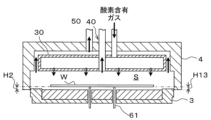
- FIG. 1 is an explanatory diagram schematically showing the configuration of the heat treatment apparatus according to the present embodiment when viewed from the side.
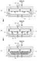
- FIG. 3 is a diagram showing the state of the heat processing apparatus at each step of wafer processing according to the present embodiment.
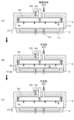
- FIG. 3 is a diagram showing the state of the heat processing apparatus at each step of wafer processing according to the present embodiment.
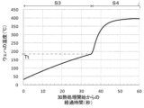
- FIG. 3 is a diagram showing the temperature history of the wafer W during the heat treatment included in the wafer treatment according to the present embodiment.
- FIG. 7 is a diagram illustrating a process space evacuation mode in another example of wafer processing according to the present embodiment.
- FIG. 7 is a diagram showing the state of the processing space in the step of terminating the heat treatment in another example of the wafer processing according to the present embodiment.
- FIG. 7 is an explanatory diagram of effects of another example of wafer processing according to the present embodiment.
- FIG. 7 is an explanatory diagram of effects of another example of wafer processing according to the present embodiment.
- FIG. 7 is a diagram showing the height of the lid member relative to the bottom member in each step of another example of wafer processing according to the present embodiment.
- FIG. 3 is an explanatory diagram of data used to determine whether the heat treatment has reached a predetermined degree of progress.
- processing solutions such as processing solutions for forming an SOC film used as a hard mask
- wafer a substrate such as a semiconductor wafer (hereinafter referred to as "wafer").
- a heat treatment is performed to heat the substrate in a treatment container of a heat treatment apparatus.
- the inside of the processing container is evacuated for the purpose of recovering defect-causing substances generated within the processing container during heating.
- a defect-causing substance is a substance that causes defects when attached to a substrate.
- the defect-causing substances may not be completely recovered.
- increasing the amount of exhaust gas from the processing container or lengthening the exhaust time can recover more defect-causing substances, but this may result in the thickness of the coating film becoming uneven within the plane of the substrate. .
- the technology according to the present disclosure is capable of reducing the amount of heat generated within the processing container (specifically, within the processing space formed by the processing container) during heating without impairing the uniformity of the coated film after heat treatment within the substrate surface. To suppress defects caused by substances from occurring on a substrate.
- FIG. 1 is an explanatory diagram schematically showing the configuration of the heat treatment apparatus according to the present embodiment viewed from the side.
- the heat processing apparatus 1 has a processing container 2 that forms a processing space S that accommodates a wafer W as a substrate.
- This processing container 2 includes a bottom member 3 having a heating plate 11, and a lid member 4 that forms a processing space S between the bottom member 3 and the bottom member 3, including a ceiling portion 4a facing a mounting surface 11a, which will be described later, of the bottom member 3. have.
- the processing container 2 is provided within a housing (not shown).
- the bottom member 3 is supported via a support member 6 on a base 5 of the casing (not shown).
- the bottom member 3 includes a support base 12 made of a flat cylindrical body with a recess formed inside the peripheral edge 12a.
- a hot plate 11 is provided in the recess of the support base 12.
- the upper surface 11a of the hot plate 11 is a mounting surface on which the wafer W is mounted.
- a plurality of gap pins (not shown) that support the lower surface of the wafer W may be provided on the upper surface 11a (hereinafter referred to as the mounting surface 11a) of the hot plate 11.
- a heater 13 serving as a heating section for heating the wafer W is provided inside the hot plate 11 .
- the heater 13 can heat the wafer W by heating the mounting surface 11a. Specifically, the heater 13 heats the wafer W placed on the placement surface 11a by heating the placement surface 11a, and also heats the wafer W located at a distance from the placement surface 11a. Can be heated.
- the heater 13 is controlled by a control section 100, which will be described later.
- the ceiling portion 4a of the lid member 4 is formed into a disk shape having a larger diameter than the bottom member 3. Further, the lid member 4 has a side wall portion 4b that closes the periphery of the gap between the bottom member 3 and the ceiling portion 4a to form a processing space S.
- the side wall portion 4b is formed in an annular shape in plan view.
- This lid member 4 is raised and lowered by a raising and lowering mechanism 20.
- the elevating mechanism 20 has a drive source such as a motor that generates a driving force for raising and lowering the lid member 4, that is, a driving force for adjusting the height of the lid member 4 with respect to the bottom member 3. provided.
- This elevating mechanism 20 is controlled by a control section 100, which will be described later.
- the elevating mechanism 20 can form the processing space S by lowering the lid member 4.
- the elevating mechanism 20 can open the processing space S by raising the lid member 4.
- the elevating mechanism 20 can change the volume of the processing space S by raising and lowering the lid member 4, that is, by adjusting the height of the lid member 4 with respect to the bottom member 3.
- the elevating mechanism 20 constitutes an adjusting mechanism that adjusts the height of the lid member 4 with respect to the bottom member 3, and also constitutes a changing unit that changes the volume of the processing space S.
- a shower head 30 is provided on the ceiling portion 4a of the lid member 4.
- the shower head 30 supplies oxygen-containing gas, that is, oxygen-containing gas, downward from the ceiling portion 4a.
- the oxygen-containing gas supplied by the shower head 30 is, for example, dry air.
- the shower head 30 supplies an inert gas that does not contain oxygen downward from the ceiling portion 4a.
- the inert gas supplied by the shower head 30 is, for example, nitrogen gas.
- the shower head 30 has a plurality of discharge holes 31 and a gas distribution space 32.
- the discharge holes 31 are each formed on the lower surface of the shower head 30.
- the discharge holes 31 are arranged substantially uniformly, for example, in a central portion of the lower surface of the shower head 30, other than the exhaust port 41, which will be described later.
- the plurality of discharge holes 31 include a first discharge hole located above the peripheral edge of the wafer W on the hot plate 11 and a second discharge hole located above the center of the wafer W on the hot plate 11. include.
- the gas distribution space 32 distributes the oxygen-containing gas or inert gas introduced into the shower head 30 and supplies it to each discharge hole 31 .
- An introduction pipe 33 for introducing oxygen-containing gas or inert gas into the shower head 30 is connected to the shower head 30 .
- a gas source 35 that stores oxygen-containing gas is connected to the introduction pipe 33 via a supply pipe 34 .
- the supply pipe 34 is provided with a supply equipment group 36 including an on-off valve, a flow control valve, etc. that control the flow of oxygen-containing gas.
- a gas source 38 for storing inert gas is connected to the introduction pipe 33 via a supply pipe 37 .
- the supply pipe 37 is provided with a supply equipment group 39 including an on-off valve, a flow rate control valve, etc. that control the flow of inert gas.
- the supply equipment groups 36 and 39 are controlled by a control unit 100, which will be described later.
- the shower head 30, the introduction pipe 33, the supply pipe 37, and the supply equipment group 39 constitute a gas supply section that supplies inert gas to the processing space S.
- the supply pipe 34 and the supply equipment group 36 constitute another gas supply unit that supplies oxygen-containing gas to the processing space S.
- the heat treatment apparatus 1 is provided with a central exhaust section 40 and a peripheral exhaust section 50.
- the central exhaust section 40 and the peripheral exhaust section 50 constitute an exhaust section that exhausts the processing space S.
- the central exhaust section 40 exhausts the processing space S from a position above the mounting surface 11a and corresponding to a position near the center of the wafer W on the mounting surface 11a (in the illustrated example, the central position). Exhaust.
- the central exhaust section 40 has an exhaust port 41 .
- the exhaust port 41 is provided at a position near the center of the lower surface of the shower head 30 (in the illustrated example, the central position) and opens downward.
- the central exhaust section 40 exhausts the processing space S through the exhaust port 41.
- the central exhaust section 40 has a central exhaust path 42 formed to extend upward from the exhaust port 41.
- An exhaust device 44 such as a vacuum pump is connected to the central exhaust path 42 via an exhaust pipe 43.
- the exhaust pipe 43 is provided with an exhaust equipment group 45 having valves and the like for adjusting the exhaust amount.
- the exhaust device 44 and the exhaust equipment group 45 are controlled by a control section 100, which will be described later.
- the peripheral edge exhaust part 50 is located above the mounting surface 11a and corresponds to a position near the peripheral edge of the wafer W on the mounting surface 11a (in the illustrated example, a position slightly outside the peripheral edge of the wafer W).
- the processing space S is evacuated from the position.
- the peripheral exhaust part 50 has an exhaust port 51 .
- the exhaust port 51 opens downward from the lower surface of the ceiling portion 4a so as to surround the outer periphery of the shower head 30.
- the exhaust port 51 may be a plurality of exhaust holes arranged along the outer periphery of the shower head 30.
- the peripheral exhaust part 50 exhausts the processing space S through the exhaust port 51.
- the peripheral exhaust section 50 has a peripheral exhaust path 52 that communicates with the exhaust port 51.
- An exhaust device 54 such as a vacuum pump is connected to the peripheral exhaust path 52 via an exhaust pipe 53.
- the exhaust pipe 53 is provided with an exhaust equipment group 55 having valves and the like for adjusting the exhaust amount.
- the exhaust device 54 and the exhaust equipment group 55 are controlled by a control section 100, which will be described later.
- the ceiling portion 4a is configured to be heated.
- the ceiling portion 4a has a built-in heater (not shown) that heats the ceiling portion 4a.
- This heater is controlled by a control section 100, which will be described later, to adjust the temperature of the ceiling section 4a (specifically, for example, the shower head 30) to a predetermined temperature.
- a lifting mechanism 60 for lifting and lowering the wafer W is provided below the bottom member 3.
- the elevating mechanism 60 is configured such that an elevating pin 61 serving as a transfer member for transferring the wafer W to and from a transfer mechanism (not shown) provided outside the processing container 2 passes through the support table 12 and the hot plate 11. It is set in. For example, at least three lifting pins 61 are provided at equal intervals in the circumferential direction of the hot plate 11.
- the elevating pin 61 is moved up and down by the elevating mechanism 62, and is configured to be able to protrude above the hot plate 11 when raised.
- the elevating mechanism 62 has a drive source such as a motor that generates a driving force for elevating the elevating pin 61, and is provided on the base 5, for example.
- This elevating mechanism 62 is controlled by a control section 100, which will be described later.
- the elevating mechanism 60 constitutes an adjusting mechanism that adjusts the height of the wafer W with respect to the hot plate 11.
- the heat treatment apparatus 1 described above includes a control section 100.
- the control unit 100 is, for example, a computer including a processor such as a CPU, a memory, and the like, and has a storage unit 101.
- the storage unit 101 stores, for example, a program including commands for controlling various operations of the heat treatment apparatus 1, which will be described later.
- the above program may be one that has been recorded on a computer-readable storage medium H, and may have been installed in the control unit 100 from the storage medium H.
- the storage medium H may be one for temporary storage or one for non-temporary storage. Further, part or all of the program may be realized by dedicated hardware (circuit board).
- FIGS. 2 and 3 are diagrams each showing the state of the heat processing apparatus 1 at each step of wafer processing according to the present embodiment.
- FIG. 4 is a diagram showing the temperature history of the wafer W during the heat treatment included in the wafer treatment according to the present embodiment. Note that all of the wafer processing according to the present embodiment illustrated below is performed under the control of the control unit 100.
- Step S1 Carrying in wafer W
- a wafer W is loaded into the heat treatment apparatus 1. Specifically, after the lid member 4 is raised, the wafer W on which the SOC film is formed as the coating film is moved to above the hot plate 11 by a transport mechanism (not shown). Thereafter, the lifting pin 61 is lifted, and the wafer W is transferred to the lifting pin 61 as shown in FIG. 2(A), and the height of the wafer W with respect to the hot plate 11 is raised to the transfer height Hd.
- the delivery height Hd is, for example, 30 mm to 50 mm.
- the exhaust from the central exhaust section 40 is turned off.
- the exhaust by the peripheral exhaust section 50 is always turned on during wafer processing.
- the heater 13 is controlled so that the temperature of the mounting surface 11a of the hot plate 11 is, for example, 200 to 450°C. Note that during wafer processing, the heater 13 is controlled so that, for example, the temperature of the mounting surface 11a of the hot plate 11 is constant.
- a heater (not shown) for the ceiling portion 4a is controlled so that, for example, the temperature of the ceiling portion 4a (specifically, the shower head 30) is constant at a predetermined temperature during wafer processing.
- Step S2 Start of heat treatment
- the height of the wafer W with respect to the hot plate 11 is set to a predetermined height that is a predetermined distance away from the hot plate 11, that is, the first height H1, and the heat treatment is started.
- the lid member 4 is lowered to form a processing space S as shown in FIG. 2(B).
- the lifting pin 61 is lowered, and the height of the wafer W with respect to the hot plate 11 is different from the delivery height Hd and is lower than the delivery height Hd.
- the height is assumed to be H1.
- the heat processing begins.
- the first height H1 is, for example, 2 mm to 10 mm, and is set in advance and stored in the storage unit 101. Further, during the heat treatment, the height of the lid member 4 with respect to the bottom member 3, that is, the volume of the processing space S, is constant.
- Step S3 Heating at the first height H1
- the wafer W is heated to the first height H1, and exhaust is performed by the peripheral exhaust section 50 to recover defect-causing substances generated in the processing space S during heating.
- the height of the wafer W with respect to the hot plate 11 is maintained at the first height H1, and the oxygen-containing gas is supplied from the shower head 30 to the processing space S.
- exhaust is performed by the peripheral exhaust section 50, and defect-causing substances in the processing space S, such as defect-causing substances generated from the SOC film during heating, are recovered.
- oxygen-containing gas may be discharged from the shower head 30 before the heating process starts.
- Step S3 is performed until the heat treatment reaches a predetermined degree of progress. Specifically, step S3 is performed until the temperature of the wafer W reaches a predetermined temperature Tt, which is slightly lower than the temperature at which the crosslinking reaction with oxygen in the SOC film starts, as shown in FIG.
- the determination as to whether the heat treatment has reached a predetermined degree of progress is made, for example, when the height of the wafer W with respect to the hot plate 11 is a first height. This is performed based on whether or not the time that has passed since being set to H1 has exceeded a predetermined time T1.
- the control unit 100 determines that a predetermined degree of progress has been reached, that is, the predetermined temperature Tt has been reached.
- the “predetermined time T1” used for this determination varies depending on the type of SOC film, and is set in advance based on user input via an input unit such as a keyboard or touch panel (not shown), and is stored in the storage unit 101. There is.
- Step S4 Lowering the wafer W
- the wafer W is lowered. Specifically, after the heat treatment reaches a predetermined degree of progress, the elevating pins 61 are lowered and the wafer W is placed on the mounting surface 11a of the hot plate 11.
- Step S5 Heating while placed
- the wafer W is heated while being placed on the hot plate 11, and exhaust is performed by the peripheral exhaust section 50 and the central exhaust section 40 to eliminate defect-causing substances generated in the processing space S during heating. Collection takes place.
- the state in which the wafer W is placed on the hot plate 11 is maintained, and the oxygen-containing gas is supplied from the shower head 30 to the processing space S.
- the temperature of the wafer W heated by the hot plate 11 exceeds a certain temperature
- the material in the SOC film on the wafer W undergoes a crosslinking reaction with oxygen in the processing space S and the like due to heat.
- the SOC film becomes hardened, that is, etched resistant, due to a crosslinking reaction occurring in the film.
- the exhaust equipment group 45 is controlled, and the exhaust by the central exhaust part 40 is switched from OFF to ON, and both the exhaust by the peripheral exhaust part 50 and the exhaust by the central exhaust part 40 are performed.
- defect-causing substances in the processing space S such as defect-causing substances generated from the SOC film during heating, are recovered.
- This step S5 is performed until a predetermined time T2 elapses after the wafer W is placed on the hot plate 11.
- the predetermined time T2 (i.e., the heating time when placed on the hot plate 11) is, for example, 30 seconds to 120 seconds, and the predetermined time T1 (i.e., the heating time at the first height H1) is, for example, 30 seconds to 120 seconds. ) is 0.5 to 1.5 times the predetermined time T2.
- the timing at which the exhaust gas by the central exhaust section 40 is switched from OFF to ON is, for example, immediately after the start of heating in step S5 (that is, immediately after the wafer W is placed on the hot plate 11). Further, the timing may be after a predetermined time T3 has elapsed after the heating in step S5 is started (that is, after the wafer W is placed on the hot plate 11). The reason will be explained later.
- the predetermined time T3 is, for example, 2 seconds or more and 10 seconds or less.
- Step S6 End of heat treatment
- the wafer W is separated from the mounting surface 11a by the lifting pin 61, and the lid member 4 is lifted to open the processing space S, and the heat treatment is completed.
- step S5 for example, the supply of oxygen-containing gas from the shower head 30 to the processing space S, the exhaust by the central exhaust part 40, and the exhaust by the peripheral exhaust part 50 are maintained ON, and the elevator is moved up and down.
- the pin 61 and the lid member 4 are raised simultaneously.
- the wafer W rises to the transfer height Hd, and the processing space S is opened.
- Step S7 Carrying out wafer W
- the wafer W is carried out of the heat treatment apparatus 1. Specifically, the elevating pin 61 is lowered, and the wafer W is delivered to a transport mechanism (not shown), and is moved from above the hot plate 11 by the transport mechanism. This completes the wafer processing according to this example.
- wafer processing according to Comparative Examples 1 and 2 below can be considered.
- Comparative Examples 1 and 2 had the following problems. That is, in the wafer processing according to Comparative Example 1, no defects were generated on the surface of the wafer W after the wafer processing, but the thickness of the SOC film after the wafer processing was sometimes thicker at the center of the wafer W. Furthermore, in the wafer processing according to Comparative Example 2, depending on the type of SOC film, it may not be possible to sufficiently recover defect-causing substances in the processing space S, and defects may occur on the surface of the wafer W after wafer processing. In some cases, even if the evacuation time was increased, the above-mentioned defects could not be sufficiently reduced.
- the wafer W is placed on the hot plate 11 after being heated at the first height H1. Therefore, the temperature change of the wafer W immediately after the start of the heat treatment and the temperature change of the wafer W immediately after being placed on the hot plate 11 are relatively gentle. Therefore, according to the wafer processing according to this example, it is possible to suppress the generation of defect-causing substances P that are difficult to recover, which may occur during a period when the temperature of the wafer W is drastically changing. Furthermore, in the heat treatment of the wafer W on which the SOC film is formed, the fluidity of the SOC film is highest in the initial stage, and the film thickness is likely to be influenced by exhaust gas.
- the exhaust by the central exhaust section 40 is in an OFF state. Therefore, by performing central exhaust during the heat treatment, it is possible to suppress the thickness of the SOC film from increasing at the center of the wafer W.
- the height of the wafer W relative to the hot plate 11 during heating in step S5 is the height at which the wafer W is placed on the hot plate 11.
- the present invention is not limited to this, and any height may be used as long as it is closer to the hot plate 11 than the first height H1. The same applies to the following examples.
- the height of the wafer W with respect to the hot plate 11 is set to the first height H1 which is a predetermined distance away from the hot plate 11, and the heat treatment of the wafer W is started.
- step (a) when the heat treatment reaches a predetermined degree of progress, the height of the wafer W with respect to the hot plate 11 is made lower than the first height H1, and the wafer W is placed on the hot plate 11. or a close state, and a step of switching the exhaust gas in the processing space S from OFF to ON. Therefore, the temperature of the wafer W changes relatively slowly over the entire period of the heat treatment.
- the exhaust of the processing space S (specifically, the exhaust by the central exhaust section 40) is turned on in order to improve the recovery efficiency of defect-causing substances in the processing space S. This is after the heat treatment has progressed to a predetermined degree, that is, after the fluidity of the coating film on the wafer W has decreased. Therefore, it is possible to suppress the occurrence of in-plane non-uniformity in film thickness due to exhaustion of the processing space S (specifically, exhaustion by the central exhaust section 40).
- defects caused by substances generated in the processing space S during heating can occur on the wafer W without impairing the uniformity of the coating film on the wafer W surface after the heat treatment. can be suppressed.
- the timing at which the exhaust by the central exhaust section 40 is switched from OFF to ON may be after a predetermined time T3 has elapsed since the heating plate 11 was placed.
- the heating time at the first height H1, etc. heating only at the first height H1 may affect the fluidity of the coating film and the influence of the exhaust from the central exhaust section 40. This is because you may not be able to drop it enough to avoid being affected.
- FIG. 5 is a diagram showing an exhaust form of the processing space S in another example of wafer processing according to the present embodiment.
- the lid member 4 in the process of terminating the heat treatment in step S6, the lid member 4 is raised while the exhaust by the central exhaust section 40 and the exhaust by the peripheral exhaust section 50 are kept ON, and the processing space S is It was open.
- the exhaust by the peripheral exhaust part 50 is turned off while the exhaust by the central exhaust part 40 is maintained ON, and then, After the predetermined time T2 has elapsed, the lid member 4 may be raised and the processing space S may be opened. Thereby, when the processing space S is opened, it is possible to suppress the defect-causing substance from leaking out of the processing container 2 through the gap between the bottom member 3 and the lid member 4.
- FIG. 6 is a diagram showing the state of the processing space S at the step of terminating the heat treatment in step S6 in another example of wafer processing according to the present embodiment.
- the elevating pin 61 is raised, that is, the wafer W is raised while the exhaust by the central exhaust part 40 and the exhaust by the peripheral exhaust part 50 are kept ON.
- the lifting and the lifting of the lid member 4 were performed simultaneously, and the wafer W was raised to the transfer height Hd, and the processing space S was opened.
- the process of terminating the heat treatment in step S6 first, as shown in FIG.
- the lifting pin 61 is Only the raising may be performed, and the height of the wafer W with respect to the hot plate 11 may be set to the second height H2, and the processing space S may remain formed. Thereafter, after a predetermined time T3 has elapsed, the lifting pins 61 are raised again and the lid member 4 is raised simultaneously, and the wafer W is raised to the transfer height Hd, and the processing space S is opened. good.
- the first height H1 and the second height H2 may be the same or different.
- the second height H2 is set in advance and stored in the storage unit 101, for example, like the first height H1. Further, the second height H2 may be calculated and determined in advance by the control unit 100 as described below, and may be stored in the storage unit 101. That is, the control unit 100 obtains the detection result of the amount of warpage of the wafer W to be processed from an external detection device (not shown), calculates and determines the second height H2 in advance based on the detection result, It may be stored in the storage unit 101.
- the external detection device is, for example, a known device that images the wafer W from the side and detects the amount of warpage of the wafer W from the imaged result.
- the second height H2 is calculated and determined by the control unit 100 from the detection result of the amount of warpage of the wafer W to be processed, as described below. That is, the control unit 100 calculates the sum of the obtained warp amount Wp of the wafer W and the default value H20 of the second height H2 stored in the storage unit 101, and the result is used as the actual second height H2.
- the lid member 4 has the height H3 of the peripheral edge of the wafer W with respect to the lower end of the peripheral edge of the lid member 4 is different, when the lifting pin 61 is raised again and the lid member 4 is raised simultaneously and the processing space S is opened, the lid member The airflow passing under the peripheral edge of the wafer W and flowing into the surface of the wafer W also differs. Specifically, when the lifting pin 61 is raised again and the lid member 4 is raised simultaneously to open the processing space S, if the above-mentioned height H3 is large, the airflow flowing to the surface of the wafer W is reduced, and the above-mentioned If the height H3 is small, the amount of air flowing into the surface of the wafer W increases.
- the surface of the wafer W is The airflow flowing in is also approximately constant. As a result, the influence of the amount of warpage of the wafer W on the heat treatment results can be suppressed.
- the exhaust form of the processing space S in the process of terminating the heat treatment in step S6 may be the same as in Example 6 of the wafer processing described above. That is, in the process of terminating the heat treatment in step S6, of the exhaust by the central exhaust part 40 and the exhaust by the peripheral exhaust part 50, only the exhaust by the peripheral exhaust part 50 is turned off before the lid member 4 is raised, and then After the time T3 has elapsed, the lid member 4 may be raised and the processing space S may be opened.
- the supply pipe 37, gas source 38, and supply equipment group 39 used for supplying inert gas to the processing space S may be omitted from the heat processing apparatus 1. can.
- FIGS. 7 and 8 are explanatory diagrams of effects of other examples of wafer processing according to this embodiment.
- the gas supplied to the processing space S during the heat treatment was an oxygen-containing gas, and switching to an inert gas was not particularly performed.
- the gas supplied to the processing space S is switched from an oxygen-containing gas to an inert gas, and the oxygen-containing gas in the processing space S is replaced with the inert gas. That is, in this example, heating in an oxygen-containing gas atmosphere is switched to heating in a low oxygen concentration atmosphere (specifically, heating in an inert gas atmosphere) during the heat treatment.
- the timing at which the gas supplied to the processing space S is switched from an oxygen-containing gas to an inert gas is, for example, during the heating of the wafer W placed on the hot plate 11 in step S5.
- the above-mentioned timing is, for example, during the heating in step S5, when the crosslinking reaction due to the reaction with oxygen in the SOC film on the wafer W reaches a predetermined degree of progress. This is when the predetermined temperature Ts, which is higher than the temperature at which the crosslinking reaction in the SOC film is completed, is reached.
- the control unit 100 determines whether the crosslinking reaction due to the reaction with oxygen in the SOC film has reached a predetermined degree of progress, that is, whether the temperature of the wafer W has reached a predetermined temperature Ts, for example, the wafer W is placed on the hot plate 11. This is performed based on whether the time that has passed since the placement has exceeded a predetermined time T11.
- the control unit 100 determines that a predetermined degree of progress has been reached, that is, the predetermined temperature Ts has been reached.
- the "predetermined time T11" used for this determination varies depending on the type of SOC film, and is set in advance based on user input via an input unit such as a keyboard or touch panel (not shown), and is stored in the storage unit 101. There is.
- defect-causing substances P1 may be scattered from the SOC film, as shown in FIG. 7(A). .
- This scattering of the defect-causing substance P1 will stop as the heat treatment progresses.
- the above-mentioned defect-causing substance P1 is removed from the SOC film on the wafer W, as shown in FIG. 7(B).
- the fine particles P2 of the vaporized material may combine with the oxygen in the processing space S to become another defect-causing substance P3 with a large mass.
- This defect-causing substance P3 not only has a large mass but also is generated in large quantities. Therefore, the exhaust by the central exhaust part 40 and the exhaust by the peripheral exhaust part 50 cannot completely recover the defect-causing substance P3, and as shown in FIG. There are cases where the particles S are filled with the particles and remain attached to the entire surface of the wafer W after wafer processing is completed.
- the gas supplied to the processing space S is Switch from oxygen-containing gas to inert gas. Therefore, even if the relatively large defect-causing substance P1 described above is scattered during a period including immediately after the wafer W is placed on the hot plate 11, the defect-causing substance P1 will be scattered as shown in FIG. 8(A). Since it does not combine with the above-mentioned fine particles P2 and oxygen in the processing space S, it does not change into another defect-causing substance P3 having a large mass (see FIG. 7(B)).
- P4 is the reduced defect-causing substance.
- the reduced defect-causing substance P4 can be easily recovered by exhaust through the central exhaust section 40 and exhaust through the peripheral exhaust section 50, as shown in FIG. 8(B). Therefore, it is possible to suppress the defect-causing substance P3 (see FIG. 2(B)) and other defect-causing substances from filling the processing space S at the end of the heat treatment, and the wafer W after the wafer processing is completed. It is possible to prevent defect-causing substances from remaining attached to the entire surface of the substrate.
- the exhaust by the central exhaust section 40 may be switched from OFF to ON at the same time as the switching.
- the timing at which the gas supplied to the processing space S is switched from an oxygen-containing gas to an inert gas is when heating in step S5 is started, that is, in step S4.
- the wafer W may be lowered to be placed on the hot plate 11.
- FIG. 9 is a diagram showing the height of the lid member 4 with respect to the bottom member 3 in each step of another example of wafer processing according to the present embodiment.
- the height of the lid member 4 with respect to the bottom member 3 that is, the volume of the processing space S
- the volume of the processing space S was constant during the heat treatment.
- the volume of the processing space S may be made smaller than in the heating step in an oxygen-containing gas atmosphere. good.
- the volume of the processing space S may be made larger in the heating step in an inert gas atmosphere than in the replacement step.
- a heating step is performed in an oxygen-containing gas atmosphere with the height of the lid member 4 relative to the bottom member 3 set to a first height H11
- the replacement step may be performed with the height of the lid member 4 relative to the bottom member 3 set to a second height H12 that is lower than the first height H12.
- the heating step in an inert gas atmosphere is performed with the height of the lid member 4 relative to the bottom member 3 set to the third height H13 which is higher than the second height H12. good.
- the third height H13 may be the same as or different from the first height H11.
- the time required to replace the atmosphere in the processing space S with an inert gas can be shortened.
- generation of the aforementioned defect-causing substance P3 having a large mass can be suppressed.
- the heating step in an inert gas atmosphere by increasing the volume of the processing space S as described above, that is, by increasing the height of the lid member 4 with respect to the bottom member 3, it is possible to The airflow can be made more uniform within the wafer plane. Further, it is possible to prevent the lid member 4 (specifically, the shower head 30) from being contaminated by adhesion of defect-causing substances.
- the heating step in an inert gas atmosphere when the volume of the processing space S is made larger than in the replacement step as described above, the flow rate of the inert gas supplied to the processing space S is increased in the replacement step, and the volume of the inert gas is increased in the replacement step. It may be relatively small in the heating process in an atmosphere of This makes it possible to shorten the time required to replace the atmosphere in the processing space S with inert gas in the replacement step, and to suppress the amount of inert gas consumed during the entire heat treatment.
- the determination of whether the heat treatment has reached a predetermined degree of progress is performed using a keyboard, touch panel, etc. (not shown). This is performed based on a predetermined time T1 that is preset based on user input via the input unit.
- the method of determining whether the heat treatment has progressed to a predetermined degree is not limited to this.
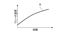
- data D1 indicating a relationship R as shown in FIG. 10 is stored in the storage unit 101 in advance.
- the above relationship R is the temperature of the wafer W when the wafer W is heated with the hot plate 11 at the current set temperature and the height of the wafer W relative to the hot plate 11 set to a preset first height H1. This is the relationship with heating time.
- the predetermined temperature (that is, the target temperature achieved by heating at the first height H1) Tt is received from the user via an input unit such as a keyboard or a touch panel (not shown), and is stored in the storage unit 101 in advance. I'll let you. Then, a determination as to whether the temperature of the wafer W has reached a predetermined temperature Tt may be made based on the data D1 stored in the storage unit 101. Specifically, the control unit 100 calculates and determines the time T21 required to reach the predetermined temperature Tt based on the data D1 stored in the storage unit 101 and the predetermined temperature Tt. Based on the determination of whether or not the time elapsed since the height of the wafer W with respect to 11 was set to the first height H1, the temperature of the wafer W has reached the predetermined temperature Tt. A determination may be made.
- the time T21 required to reach the predetermined temperature Tt is output from an external output such as a display unit (for example, a liquid crystal display) not shown. It may also be output to the outside via the section.
- a display unit for example, a liquid crystal display
- the relationship R between the temperature of the wafer W and the heating time when the wafer W is heated with the height of the wafer W relative to the hot plate 11 as the first height H1 is determined for each temperature of the hot plate 11 and with respect to the hot plate 11.
- the data D2 indicating each height of the wafer W may be stored in the storage unit 101 in advance. Then, it may be determined whether the temperature of the wafer W has reached a predetermined temperature Tt based on the data D2 stored in the storage unit 101.
- the current temperature of the hot plate 11, the predetermined temperature Tt, and the set values of the first height H1 are received from the user via an input unit such as a keyboard or touch panel (not shown), and are stored in the storage unit 101 in advance. I'll let you. Furthermore, the control unit 100 calculates and determines the time T21 required to reach the predetermined temperature Tt based on this information and the data D2. Then, the control unit 100 determines whether or not the time that has elapsed since the height of the wafer W with respect to the hot plate 11 was set to the first height H1 has exceeded the above-mentioned time T21, and the temperature of the wafer W is set to a predetermined value. A determination is made as to whether the temperature Tt has been reached.
- the relationship R between the temperature of the wafer W and the heating time when the wafer W is heated with the height of the wafer W relative to the hot plate 11 as the first height H1 is determined by the set temperature of the hot plate 11 and the heating time relative to the hot plate 11. It is affected not only by the height of the wafer W but also by the set temperature of the lid member 4 (specifically, the shower head 30). Therefore, data D3 indicating the above relationship R for each temperature of the hot plate 11, for each height of the wafer W with respect to the hot plate 11, and for each temperature of the lid member 4 may be stored in the storage unit 101 in advance. Then, a determination as to whether the temperature of the wafer W has reached a predetermined temperature Tt may be made based on the data D3 stored in the storage unit 101.
- set values for the temperature of the lid member 4, the temperature of the hot plate 11, the predetermined temperature Tt, and the first height H1 are received from the user via an input unit such as a keyboard or touch panel (not shown), and It is stored in the storage unit 101. Furthermore, the control unit 100 calculates and determines the time T21 required to reach the predetermined temperature Tt based on this information and the data D2. Then, the control unit 100 determines whether or not the time that has elapsed since the height of the wafer W with respect to the hot plate 11 was set to the first height H1 has exceeded the above-mentioned time T21, and the temperature of the wafer W is set to a predetermined value. A determination is made as to whether the temperature Tt has been reached.
- the temperature of the wafer W reaches the predetermined temperature Tt, which is determined as information used to determine whether the temperature of the wafer W has reached the predetermined temperature Tt.
- the time T21 required to complete the process may be outputted to the outside via an external output unit such as a display unit (for example, a liquid crystal display) not shown.
- candidates for information to be used for determining whether the temperature of the wafer W has reached a predetermined temperature Tt may be determined based on the data D2. For example, the set values of the temperature of the hot plate 11, the predetermined temperature Tt, and the allowable range of the time T21 required to reach the predetermined temperature Tt are entered via an input unit such as a keyboard or touch panel (not shown). It is accepted from the user and stored in the storage unit 101 in advance. Further, the control unit 100 determines a candidate combination of the time T21 and the first height H1 based on this information and the data D2. The determined candidates may be output to the outside via an external output unit such as a display unit (for example, a liquid crystal display) not shown.
- a display unit for example, a liquid crystal display
- candidates for information used to determine whether the temperature of the wafer W has reached a predetermined temperature Tt may be determined based on the data D3.
- the set values of the temperature of the lid member 4, the temperature of the hot plate 11, the predetermined temperature Tt, and the allowable range of the time T21 required to reach the predetermined temperature Tt can be set using a keyboard or touch panel (not shown).
- the information is received from the user via the input unit and stored in the storage unit 101 in advance. Further, the control unit 100 determines a candidate combination of the time T21 and the first height H1 based on this information and the data D3.
- the determined candidates may be output to the outside via an external output unit such as a display unit (for example, a liquid crystal display) not shown.
- the candidate combination of the time T21 and the height H1 determined based on the data D2 or the data D3 is determined based on the detection result of the amount of warpage of the wafer W to be processed as follows. It may be possible to narrow it down. That is, when the shape of the wafer W is convex in side view (the central part protrudes upward) and the amount of warpage of the wafer W is large, the distance from the hot plate 11 at the periphery of the wafer W becomes short. As a result, the amount of heating increases, and as a result, the in-plane uniformity of the film thickness may be impaired.
- the control unit 100 selects the candidate combination of the time T21 and the first height H1 as the first height. It may be possible to narrow down the selection to only those with a length H1 of 3 mm or more.
- the detection result of the amount of warpage of the wafer W to be processed is obtained, for example, from an external detection device (not shown). Further, information other than the amount of warpage of the wafer W, which is necessary for narrowing down the combination candidates, is stored in advance in the storage unit 101, for example.
- the first height H1 may be adjusted as follows based on the detection result of the amount of warpage of the wafer W to be processed. That is, a basic value of the first height H1 is set, and for example, if the wafer W is along a convex shape in side view and the amount of warpage is 500 ⁇ m or more, the first height H1 is larger than the basic value. A value may be applied, otherwise a base value may be applied to the first height H1.
- the height of the lid member 4 with respect to the bottom member 3 was adjusted by raising and lowering the lid member 4, but it may also be adjusted by raising and lowering the lid member 4.
- the height of the wafer W with respect to the hot plate 11 was adjusted by raising and lowering the wafer W in the above description, it may be adjusted by raising and lowering the hot plate 11.
- the SOC film has been cited as an example of the coating film above, the technology according to the present disclosure can also be used for other coating films.
- a heat treatment device that heats a substrate on which a coating film is formed, a processing container forming a processing space that accommodates the substrate; a heating plate having a mounting surface on which the substrate accommodated in the processing space is mounted, and a heating section that heats the substrate; an adjustment mechanism that adjusts the height of the substrate relative to the hot plate; an exhaust section that exhausts the processing space; comprising a control unit;
- the control unit includes: (A) the step of setting the height of the substrate relative to the hot plate to a predetermined height at a predetermined distance from the hot plate and starting heat treatment of the substrate; (B) When the heat treatment reaches a predetermined degree of progress, the height of the substrate relative to the hot plate is lowered than the predetermined height, and the substrate is placed on or close to the hot plate.
- the exhaust section is a central exhaust section that exhausts the processing space from a position above the placement surface and corresponding to a position near the center of the substrate on the placement surface; a peripheral exhaust part that exhausts the processing space from a position above the mounting surface and corresponding to a position near the peripheral edge of the substrate on the mounting surface;
- the control unit includes: Maintaining the exhaust gas by the central exhaust section in the step (A), and switching it from OFF to ON in the step (B);
- the heat treatment apparatus according to Supplementary Note 1, wherein the heat treatment apparatus is controlled so that the exhaust gas by the peripheral edge exhaust part is kept ON from the step (A).
- the processing container is a bottom member including the hot plate; a lid member including a top wall facing the placement surface and forming the processing space with the bottom member; further comprising another adjustment mechanism that adjusts the height of the lid member with respect to the bottom member,
- the control unit includes: (C) At the end of the heat treatment, the exhaust from the peripheral exhaust part is turned off while the exhaust from the central exhaust part is kept ON, and then, after a predetermined period of time has elapsed, the lid member is attached to the bottom member.
- the heat treatment apparatus according to additional note 2, wherein control is performed to further perform the step of increasing the height of the treatment space and opening the treatment space.
- the control unit performs the heat treatment based on data indicating a relationship between the substrate temperature and the heating time when the height of the substrate with respect to the heat plate is the predetermined height at the current set temperature of the heat plate.
- the heat treatment apparatus according to any one of Supplementary Notes 1 to 3, which determines whether or not the progress level has reached the predetermined degree of progress, or determines information used for the determination.
- the control unit determines the predetermined height and performs the heat treatment on the basis of data indicating a relationship between substrate temperature and heating time for each temperature of the hot plate and for each height of the substrate with respect to the hot plate.
- At least one of determining whether a predetermined degree of progress has been reached, determining information used for the determination, or determining candidates for the information is performed. heat treatment equipment.
- the heat treatment apparatus according to Supplementary Note 4 further comprising a storage unit that stores the data.
- the heat treatment apparatus according to Supplementary Note 5 further comprising a storage unit that stores the data.
- [Additional Note 8] further comprising a gas supply unit that supplies an inert gas to the processing space,
- the control unit includes: The heat treatment apparatus according to any one of Supplementary Notes 1 to 7, wherein control is performed to replace oxygen-containing gas in the treatment space with an inert gas during the heat treatment.
- a heat treatment method for heating a substrate on which a coating film is formed (a) The height of the substrate relative to the heating plate having a mounting surface on which the substrate accommodated in the processing space is placed is set to a predetermined height that is a predetermined distance away from the heating plate, and heating processing of the substrate is started. process and (b) When the heat treatment reaches a predetermined degree of progress, the height of the substrate relative to the hot plate is lower than the predetermined height, and the substrate is placed on or close to the hot plate.
- a readable computer storage medium that stores a program that runs on a computer of a control unit that controls a heat treatment device so that the heat treatment device executes a heat treatment method of heating a substrate on which a coating film is formed. There it is, The heat treatment method includes: (a) The step of starting heat treatment of the substrate by setting the height of the substrate with respect to a heating plate having a mounting surface on which the substrate accommodated in the processing space is placed to a predetermined height at a predetermined distance from the heating plate.
- Heat treatment apparatus Processing container 11 Hot plate 11a Placement surface 13 Heater 20 Elevating mechanism 40 Central exhaust section 50 Peripheral exhaust section 60 Elevating mechanism 100 Control section S Processing space W Wafer
Landscapes
- Exposure Of Semiconductors, Excluding Electron Or Ion Beam Exposure (AREA)
- Control Of Resistance Heating (AREA)
- Resistance Heating (AREA)
Abstract
Description
図1は、本実施形態にかかる加熱処理装置の構成を側面から見て模式的に示した説明図である。
また、熱板11内には、ウェハWを加熱する加熱部としてのヒータ13が設けられている。ヒータ13は、載置面11aを加熱することにより、ウェハWを加熱することができる。具体的には、ヒータ13は、載置面11aを加熱することにより、載置面11aに載置されたウェハWを加熱し、また、載置面11aから離間した位置に位置するウェハWを加熱することができる。ヒータ13は後述の制御部100により制御される。
また、蓋部材4は、底部材3と天井部4aとの間の隙間の周囲を塞ぎ処理空間Sを形成する側壁部4bを有する。側壁部4bは平面視円環状に形成されている。
このように、昇降機構20は、底部材3に対する蓋部材4の高さを調整する調整機構を構成すると共に、処理空間Sの容積を変更する変更部を構成する。
シャワーヘッド30は、天井部4aから下方に、酸素を含有するガスすなわち酸素含有ガスを供給する。シャワーヘッド30が供給する酸素含有ガスは例えばドライエアである。
また、シャワーヘッド30は、天井部4aから下方に、酸素を含まない不活性ガスを供給する。シャワーヘッド30が供給する不活性ガスは例えば窒素ガスである。
シャワーヘッド30には、当該シャワーヘッド30に酸素含有ガスまたは不活性ガスを導入する導入管33が接続されている。
また、導入管33には、供給管37を介して、不活性ガスを貯留するガス源38が接続されている。供給管37には、不活性ガスの流通を制御する開閉弁や流量調節弁等を含む供給機器群39が設けられている。
供給機器群36、39は後述の制御部100により制御される。
このように、昇降機構60は、熱板11に対するウェハWの高さを調整する調整機構を構成する。
続いて、加熱処理装置1を用いて行われる加熱処理を含むウェハ処理の、本実施形態にかかる例を説明する。
図2及び図3はそれぞれ、本実施形態にかかるウェハ処理の各工程での加熱処理装置1の状態を示す図である。図4は、本実施形態にかかるウェハ処理に含まれる加熱処理中のウェハWの温度履歴を示す図である。
なお、以下で例示する本実施形態にかかるウェハ処理はいずれも、制御部100の制御の下、行われる。
まず、加熱処理装置1内にウェハWが搬入される。
具体的には、蓋部材4が上昇された後、塗布膜としてSOC膜が形成されたウェハWが、図示しない搬送機構によって、熱板11の上方まで移動される。その後、昇降ピン61が上昇され、ウェハWが図2(A)に示すように昇降ピン61に受け渡され、熱板11に対するウェハWの高さが受け渡し高さHdまで上昇する。受け渡し高さHdは例えば30mm~50mmである。
また、このとき、熱板11の載置面11aの温度が例えば200~450℃となるようにヒータ13が制御されている。なお、ウェハ処理中、ヒータ13は例えば熱板11の載置面11aの温度が一定となるように制御される。また、天井部4aに対する図示しないヒータは、ウェハ処理中、例えば天井部4a(具体的にはシャワーヘッド30)の温度が所定の温度で一定になるように制御される。
続いて、熱板11に対するウェハWの高さが、熱板11から所定の距離離れる所定の高さすなわち第1の高さH1とされ、加熱処理が開始される。
具体的には、蓋部材4が下降されて図2(B)に示すように処理空間Sが形成される。
また、蓋部材4の下降と同時または蓋部材4の下降後、昇降ピン61が下降され、熱板11に対するウェハWの高さが、受け渡し高さHdと異なり受け渡し高さHdより低い第1の高さH1とされる。このように熱板11に対するウェハWの高さが第1の高さH1とされ、処理空間Sが形成されると、加熱処理の開始となる。なお、第1の高さH1は、例えば2mm~10mmであり、予め設定され、記憶部101に記憶されている。
また、加熱処理中、底部材3に対する蓋部材4の高さ、すなわち、処理空間Sの容積は、一定である。
次に、第1の高さH1でウェハWが加熱されると共に、周縁排気部50による排気が行われ加熱中に処理空間Sに生じた欠陥原因物質の回収が行われる。
また、周縁排気部50による排気が行われ、加熱中にSOC膜から生じた欠陥原因物質等、処理空間S内の欠陥原因物質が回収される。
そして、加熱処理が所定の進行度合いになった後は、ウェハWが下降される。
具体的には、加熱処理が所定の進行度合いになった後は、昇降ピン61が下降され、ウェハWが熱板11の載置面11aに載置される。
次に、ウェハWが熱板11に載置された状態で加熱されると共に、周縁排気部50による排気及び中央排気部40による排気が行われ加熱中に処理空間Sに生じた欠陥原因物質の回収が行われる。
このステップS5は、ウェハWが熱板11に載置されてから所定の時間T2が経過するまで行われる。
ステップS5が完了すると、昇降ピン61の上昇によりウェハWが載置面11aから離されると共に、蓋部材4が上昇され処理空間Sが開放され、加熱処理が終了となる。
具体的には、ステップS5の完了後、例えば、シャワーヘッド30から処理空間Sへの酸素含有ガスの供給、中央排気部40による排気及び周縁排気部50による排気がONに維持されたまま、昇降ピン61の上昇と蓋部材4の上昇が同時に行われる。これにより、図3(B)に示すように、ウェハWが受け渡し高さHdまで上昇すると共に、処理空間Sが開放される。
その後、加熱処理装置1外へウェハWが搬出される。
具体的には、昇降ピン61が下降され、ウェハWが、図示しない搬送機構に受け渡され、当該搬送機構によって、熱板11の上方から移動される。
これで、本例にかかるウェハ処理は完了となる。
第1の高さH1でのウェハWの加熱が行われず、熱板11に載置された状態でのウェハWの加熱のみが行われ、加熱の際、最初から中央排気部40による排気及び周縁排気部50による排気の両方がONにされる。
第1の高さH1でのウェハWの加熱が行われず、熱板11に載置された状態でのウェハWの加熱のみが行われ、加熱の際、最初の10~20秒程度、中央排気部40による排気がOFFにされ、周縁排気部50による排気のみがONにされ、その後、50秒程度、中央排気部40による排気及び周縁排気部50による排気の両方がONにされる。
これは、該当する種類のSOC膜では、第1の高さH1でのウェハWの加熱が行われない場合、加熱処理開始直後且つ熱板11に載置された直後というウェハWの温度変化が激しい期間に、中央排気部40による排気を行わないと、その後に中央排気部40による排気を行っても回収することができない欠陥原因物質が生じることが理由と考えられる。
また、SOC膜が形成されたウェハWに対する加熱処理では、初期段階が、SOC膜の流動性が最も高く、排気の影響が膜厚に出やすい。それに対し、本例にかかるウェハ処理では、加熱処理の初期段階にあたる、第1の高さH1でウェハWを加熱する工程において、中央排気部40による排気はOFF状態である。したがって、加熱処理時に中央排気を行うことによりSOC膜の厚さがウェハWの中央部で厚くなるのを抑制することができる。
以上のように、本実施形態にかかる例のウェハ処理は、熱板11に対するウェハWの高さを、熱板11から所定の距離離れる第1の高さH1とし、ウェハWの加熱処理を開始する(a)工程と、加熱処理が所定の進行度合いになった際に、熱板11に対するウェハWの高さを第1の高さH1より低くし、ウェハWを熱板11に載置した状態または近接した状態にすると共に、処理空間S内の排気をOFFからONに切り替える工程と、を含む。そのため、加熱処理の全期間に亘って、ウェハWの温度変化が比較的緩やかである。したがって、ウェハWの温度変化が激しい期間に生じ得る、回収しにくい欠陥原因物質Pが発生するのを抑制することができる。また、本実施形態にかかる例のウェハ処理では、処理空間S中の欠陥原因物質の回収効率を高めるための処理空間Sの排気(具体的には中央排気部40による排気)がONにされるのは、加熱処理が所定の進行度合いになった後、すなわち、ウェハW上の塗布膜の流動性が低下した後である。したがって、上記処理空間Sの排気(具体的には中央排気部40による排気)により膜厚の面内不均一性が生じるのを抑制することができる。
図5は、本実施形態にかかるウェハ処理の他の例における、処理空間Sの排気形態を示す図である。
以上の例では、ステップS6の加熱処理を終了させる工程では、中央排気部40による排気及び周縁排気部50による排気がONに維持されたまま、蓋部材4の上昇が行われ、処理空間Sが開放されていた。これに代えて、ステップS6の加熱処理を終了させる工程では、図5に示すように、中央排気部40による排気がONに維持されたまま、周縁排気部50による排気をOFFにさせ、その後、所定の時間T2経過してから、蓋部材4の上昇が行われ、処理空間Sが開放されてもよい。これにより、処理空間Sが開放されたときに、欠陥原因物質が、底部材3と蓋部材4との間の隙間から、処理容器2外に漏れ出すのを抑制することができる。
図6は、本実施形態にかかるウェハ処理の他の例における、ステップS6の加熱処理を終了させる工程での処理空間Sの状態を示す図である。
上述のウェハ処理の例1等では、ステップS6の加熱処理を終了させる工程、中央排気部40による排気及び周縁排気部50による排気がONに維持されたまま、昇降ピン61の上昇すなわちウェハWの上昇と蓋部材4の上昇とが同時に行われ、ウェハWが受け渡し高さHdまで上昇すると共に、処理空間Sが開放されていた。これに代えて、ステップS6の加熱処理を終了させる工程では、まず、図6に示すように、中央排気部40による排気及び周縁排気部50による排気がONに維持されたまま、昇降ピン61の上昇のみが行われ、熱板11に対するウェハWの高さが第2の高さH2とされ、処理空間Sが形成されたままとしてもよい。そして、その後、所定の時間T3経過してから、昇降ピン61の再上昇と蓋部材4の上昇が同時に行われ、ウェハWが受け渡し高さHdまで上昇すると共に、処理空間Sが開放されてもよい。
なお、第1の高さH1と第2の高さH2は同じであってもよいし、異なってもよい。
また、第2の高さH2は、以下のように制御部100により予め算出され決定され、記憶部101に記憶されていてもよい。すなわち、制御部100により、処理対象のウェハWの反り量の検出結果が、図示しない外部の検出装置から取得され、上記検出結果に基づいて、第2の高さH2が予め算出され決定され、記憶部101に記憶されていてもよい。なお、上記外部の検出装置は、例えば、ウェハWを側方から撮像し撮像結果から当該ウェハWの反り量を検出する、公知の装置である。
すなわち、制御部100により、取得されたウェハWの反り量Wpと記憶部101に記憶されていた第2の高さH2のデフォルト値H20との和が算出され、その結果が実際の第2の高さH2(=Wp+H20)に決定される。これにより、蓋部材4の周縁部の下端に対するウェハWの周縁部の高さH3が、ウェハWの反り量によらず一定となる。
蓋部材4の周縁部の下端に対するウェハWの周縁部の高さH3が異なると、昇降ピン61の再上昇と蓋部材4の上昇が同時に行われ処理空間Sが開放される際に、蓋部材4の周縁部の下を通ってウェハWの表面に流れ込む気流も異なってくる。具体的には、昇降ピン61の再上昇と蓋部材4の上昇が同時に行われ処理空間Sが開放される際、上記高さH3が大きいと、ウェハWの表面に流れ込む気流が少なくなり、上記高さH3が小さいと、ウェハWの表面に流れ込む気流が多くなる。したがって、蓋部材4の周縁部の下端に対するウェハWの周縁部の高さH3をウェハWの反り量によらず一定にすることにより、上述の処理空間Sの開放の際にウェハWの表面に流れ込む気流も略一定となる。その結果、ウェハWの反り量が熱処理結果に与える影響を抑制することができる。
図7及び図8は、本実施形態にかかるウェハ処理の他の例の効果の説明図である。
以上の例では、加熱処理中、処理空間Sに供給されるガスは酸素含有ガスであり不活性ガスへの切り替えは特に行われていなかった。
それに対し、本例では、加熱処理中に、処理空間Sに供給されるガスが、酸素含有ガスから不活性ガスに切り替えられ、処理空間S内の酸素含有ガスが不活性ガスで置換される。すなわち、本例では、加熱処理の途中で、酸素含有ガスの雰囲気での加熱から、低酸素濃度雰囲気での加熱(具体的には不活性ガスの雰囲気での加熱)に切り替えられる。
具体的には、上記タイミングは、例えば、ステップS5の加熱中であって、ウェハW上のSOC膜において酸素との反応による架橋反応が所定の進行度合いになったとき、より具体的には、SOC膜における上記架橋反応が完了する温度以上の所定の温度Tsとなったときである。
図9は、本実施形態にかかるウェハ処理の他の例の各工程における、底部材3に対する蓋部材4の高さを示す図である。
以上の例では、加熱処理中、底部材3に対する蓋部材4の高さすなわち処理空間Sの容積は一定であった。これに代えて、処理空間S内の酸素含有ガスを不活性ガスへ置換する工程(以下、置換工程)において、酸素含有ガスの雰囲気での加熱工程より、処理空間Sの容積を小さくしてもよい。また、この場合、不活性ガスの雰囲気での加熱工程において、上記置換工程より、処理空間Sの容積を大きくしてもよい。
上述のウェハ処理の例1等では、加熱処理が所定の進行度合いになったか否かの判定すなわちウェハWの温度が所定の温度Ttになったか否かの判定が、図示しないキーボードやタッチパネル等の入力部を介したユーザ入力に基づいて予め設定された所定の時間T1に基づいて行われていた。
例えば、図10に示すような関係Rを示すデータD1を予め記憶部101に記憶させておく。上記関係Rは、熱板11を現在の設定温度とし、当該熱板11に対するウェハWの高さを予め設定された第1の高さH1としてウェハWを加熱したときの、ウェハWの温度と加熱時間との関係である。また、上記所定の温度(すなわち、第1の高さH1での加熱による目標到達温度)Ttを、図示しないキーボードやタッチパネル等の入力部を介してユーザから受け付けておき、予め記憶部101に記憶させておく。そして、ウェハWの温度が所定の温度Ttになったか否かの判定が、記憶部101に記憶された上記データD1に基づいて、行われてもよい。具体的には、制御部100により、記憶部101に記憶された上記データD1と所定の温度Ttとに基づいて、所定の温度Ttに到達するまでに要する時間T21が算出され決定され、熱板11に対するウェハWの高さが第1の高さH1とされてから経過した時間が上記時間T21を超えたか否かの判定に基づき、ウェハWの温度が所定の温度Ttになったか否かの判定が行われてもよい。
例えば、熱板11の温度及び上記所定の温度Ttの設定値と、所定の温度Ttに到達するまでに要する時間T21として許容される範囲とを、図示しないキーボードやタッチパネル等の入力部を介してユーザから受け付けておき、予め記憶部101に記憶させておく。また、制御部100により、これらの情報と上記データD2とに基づいて、上記時間T21と第1の高さH1との組み合わせの候補が決定される。決定された候補は、図示しない表示部(例えば液晶ディスプレイ)等の外部出力部を介して外部出力されてもよい。
例えば、蓋部材4の温度、熱板11の温度及び上記所定の温度Ttの設定値と、所定の温度Ttに到達するまでに要する時間T21として許容される範囲とを、図示しないキーボードやタッチパネル等の入力部を介してユーザから受け付けておき、予め記憶部101に記憶させておく。また、制御部100により、これらの情報と上記データD3とに基づいて、上記時間T21と第1の高さH1との組み合わせの候補が決定される。決定された候補は、図示しない表示部(例えば液晶ディスプレイ)等の外部出力部を介して外部出力されてもよい。
すなわち、ウェハWの形状が側面視凸状(中央部が上方にと突出した形状)であり当該ウェハWの反り量が大きい場合、当該ウェハWの周縁部において熱板11との距離が近くなって加熱量が多くなり、その結果、膜厚の面内均一性が損なわれるおそれがある。そのため、例えばウェハWが側面視凸状に沿っておりその反り量が500μm以上の場合は、制御部100により、上記時間T21と第1の高さH1との組み合わせの候補が、第1の高さH1が3mm以上のもののみに絞られるようにしてもよい。
なお、処理対象のウェハWの反り量の検出結果は、例えば図示しない外部の検出装置から取得される。また、上記組み合わせ候補の絞り込みに必要な、ウェハWの反り量以外の情報は、例えば記憶部101に予め記憶されている。
また、以上では、熱板11に対するウェハWの高さを、ウェハWを昇降させることで調整していたが、熱板11を昇降させることで調整してもよい。
[付記項1]
塗布膜が形成された基板を加熱する加熱処理装置であって、
基板を収容する処理空間を形成する処理容器と、
前記処理空間に収容された基板が載置される載置面と、基板を加熱する加熱部と、を有する熱板と、
前記熱板に対する基板の高さを調整する調整機構と、
前記処理空間を排気する排気部と、
制御部と、を備え、
前記制御部は、
(A)前記熱板に対する基板の高さを前記熱板から所定の距離離れる所定の高さとし基板の加熱処理を開始する工程と、
(B)前記加熱処理が所定の進行度合いになった際に、前記熱板に対する基板の高さを前記所定の高さより低くし、基板を前記熱板に載置した状態または近接した状態にすると共に、前記処理空間の排気をOFFからONに切り替える工程と、を実行するよう、制御を行う、加熱処理装置。
[付記項2]
前記排気部は、
前記載置面の上方であって、前記載置面上の基板の中央寄りの位置に相当する位置から、前記処理空間を排気する中央排気部と、
前記載置面の上方であって、前記載置面上の前記基板の周縁部寄りの位置に相当する位置から、前記処理空間を排気する周縁排気部と、を有し、
前記制御部は、
前記中央排気部による排気を、前記(A)工程でOFFに維持し、前記(B)工程でOFFからONに切り替え、
前記周縁排気部による排気を、前記(A)工程からONのまま維持するよう、制御を行う、付記項1に記載の加熱処理装置。
[付記項3]
前記処理容器は、
前記熱板を含む底部材と、
前記載置面に対向する天壁を含み、前記底部材との間で前記処理空間を形成する蓋部材と、を有し、
前記底部材に対する前記蓋部材の高さを調整する別の調整機構をさらに備え、
前記制御部は、
(C)前記加熱処理の終了時に、前記中央排気部による排気をONに維持したまま、前記周縁排気部による排気をOFFにし、その後、所定の時間経過してから、前記底部材に対する前記蓋部材の高さを高くし、前記処理空間を開放する工程をさらに実行するよう、制御を行う、付記項2に記載の加熱処理装置。
[付記項4]
前記制御部は、前記熱板の現在の設定温度における、前記熱板に対する基板の高さが前記所定の高さのときの基板温度と加熱時間との関係を示すデータに基づいて
、前記加熱処理が前記所定の進行度合いになったか否かの判定、または、当該判定に用いられる情報の決定を行う
、付記項1~3のいずれか1項に記載の加熱処理装置。
[付記項5]
前記制御部は、基板温度と加熱時間との関係を前記熱板の温度毎且つ前記熱板に対する基板の高さ毎に示すデータに基づいて 、前記所定の高さの決定、前記加熱処理が前記所定の進行度合いになったか否かの判定、当該判定に用いられる情報の決定、または、当該情報の候補の決定の少なくともいずれか1つを行う、請求項1~3のいずれか1項に記載の加熱処理装置。
[付記項6]
前記データを記憶する記憶部をさらに備える、付記項4に記載の加熱処理装置。
[付記項7]
前記データを記憶する記憶部をさらに備える、付記項5に記載の加熱処理装置。
[付記項8]
前記処理空間に不活性ガスを供給するガス供給部をさらに備え、
前記制御部は、
加熱処理中に前記処理空間内の酸素含有ガスを不活性ガスで置換するよう、制御を行う、付記項1~7のいずれか1項に記載の加熱処理装置。
[付記項9]
前記制御部は、前記(B)工程中に、前記処理空間内の酸素含有ガスを不活性ガスで置換するよう、制御を行う、付記項8に記載の加熱処理装置。
[付記項10]
塗布膜が形成された基板を加熱する加熱処理方法であって、
(a)処理空間に収容された基板が載置される載置面を有する前記熱板に対する基板の高さを、前記熱板から所定の距離離れる所定の高さとし、基板の加熱処理を開始する工程と、
(b)前記加熱処理が所定の進行度合いになった際に、前記熱板に対する基板の高さを前記所定の高さより低くし、基板を前記熱板に載置した状態または近接した状態にすると共に、前記処理空間の排気をOFFからONに切り替える工程と、を含む、加熱処理方法。
[付記項11]
塗布膜が形成された基板を加熱する加熱処理方法を、加熱処理装置によって実行させるように、当該加熱処理装置を制御する制御部のコンピュータ上で動作するプログラムを格納した読み取り可能なコンピュータ記憶媒体であって、
前記加熱処理方法は、
(a)処理空間に収容された基板が載置される載置面を有する熱板に対する基板の高さを、前記熱板から所定の距離離れる所定の高さとし、基板の加熱処理を開始する工程と、
(b)前記加熱処理が所定の進行度合いになった際に、熱板に対する基板の高さを前記所定の高さより低くし、基板を前記熱板に載置した状態または近接した状態にすると共に、前記処理空間の排気をOFFからONに切り替える工程と、を含む、加熱処理方法。
2 処理容器
11 熱板
11a 載置面
13 ヒータ
20 昇降機構
40 中央排気部
50 周縁排気部
60 昇降機構
100 制御部
S 処理空間
W ウェハ
Claims (11)
- 塗布膜が形成された基板を加熱する加熱処理装置であって、
基板を収容する処理空間を形成する処理容器と、
前記処理空間に収容された基板が載置される載置面と、基板を加熱する加熱部と、を有する熱板と、
前記熱板に対する基板の高さを調整する調整機構と、
前記処理空間を排気する排気部と、
制御部と、を備え、
前記制御部は、
(A)前記熱板に対する基板の高さを前記熱板から所定の距離離れる所定の高さとし基板の加熱処理を開始する工程と、
(B)前記加熱処理が所定の進行度合いになった際に、前記熱板に対する基板の高さを前記所定の高さより低くし、基板を前記熱板に載置した状態または近接した状態にすると共に、前記処理空間の排気をOFFからONに切り替える工程と、を実行するよう、制御を行う、加熱処理装置。 - 前記排気部は、
前記載置面の上方であって、前記載置面上の基板の中央寄りの位置に相当する位置から、前記処理空間を排気する中央排気部と、
前記載置面の上方であって、前記載置面上の前記基板の周縁部寄りの位置に相当する位置から、前記処理空間を排気する周縁排気部と、を有し、
前記制御部は、
前記中央排気部による排気を、前記(A)工程でOFFに維持し、前記(B)工程でOFFからONに切り替え、
前記周縁排気部による排気を、前記(A)工程からONのまま維持するよう、制御を行う、請求項1に記載の加熱処理装置。 - 前記処理容器は、
前記熱板を含む底部材と、
前記載置面に対向する天壁を含み、前記底部材との間で前記処理空間を形成する蓋部材と、を有し、
前記底部材に対する前記蓋部材の高さを調整する別の調整機構をさらに備え、
前記制御部は、
(C)前記加熱処理の終了時に、前記中央排気部による排気をONに維持したまま、前記周縁排気部による排気をOFFにし、その後、所定の時間経過してから、前記底部材に対する前記蓋部材の高さを高くし、前記処理空間を開放する工程をさらに実行するよう、制御を行う、請求項2に記載の加熱処理装置。 - 前記制御部は、前記熱板の現在の設定温度における、前記熱板に対する基板の高さが前記所定の高さのときの基板温度と加熱時間との関係を示すデータに基づいて、前記加熱処理が前記所定の進行度合いになったか否かの判定、または、当該判定に用いられる情報の決定を行う、請求項1~3のいずれか1項に記載の加熱処理装置。
- 前記制御部は、基板温度と加熱時間との関係を前記熱板の温度毎且つ前記熱板に対する基板の高さ毎に示すデータに基づいて、前記所定の高さの決定、前記加熱処理が前記所定の進行度合いになったか否かの判定、当該判定に用いられる情報の決定、または、当該情報の候補の決定の少なくともいずれか1つを行う、請求項1~3のいずれか1項に記載の加熱処理装置。
- 前記データを記憶する記憶部をさらに備える、請求項4に記載の加熱処理装置。
- 前記データを記憶する記憶部をさらに備える、請求項5に記載の加熱処理装置。
- 前記処理空間に不活性ガスを供給するガス供給部をさらに備え、
前記制御部は、
加熱処理中に前記処理空間内の酸素含有ガスを不活性ガスで置換するよう、制御を行う、請求項1に記載の加熱処理装置。 - 前記制御部は、前記(B)工程中に、前記処理空間内の酸素含有ガスを不活性ガスで置換するよう、制御を行う、請求項8に記載の加熱処理装置。
- 塗布膜が形成された基板を加熱する加熱処理方法であって、
(a)処理空間に収容された基板が載置される載置面を有する熱板に対する基板の高さを、前記熱板から所定の距離離れる所定の高さとし、基板の加熱処理を開始する工程と、
(b)前記加熱処理が所定の進行度合いになった際に、前記熱板に対する基板の高さを前記所定の高さより低くし、基板を前記熱板に載置した状態または近接した状態にすると共に、前記処理空間の排気をOFFからONに切り替える工程と、を含む、加熱処理方法。 - 塗布膜が形成された基板を加熱する加熱処理方法を、加熱処理装置によって実行させるように、当該加熱処理装置を制御する制御部のコンピュータ上で動作するプログラムを格納した読み取り可能なコンピュータ記憶媒体であって、
前記加熱処理方法は、
(a)処理空間に収容された基板が載置される載置面を有する熱板に対する基板の高さを、前記熱板から所定の距離離れる所定の高さとし、基板の加熱処理を開始する工程と、
(b)前記加熱処理が所定の進行度合いになった際に、前記熱板に対する基板の高さを前記所定の高さより低くし、基板を前記熱板に載置した状態または近接した状態にすると共に、前記処理空間の排気をOFFからONに切り替える工程と、を含む、加熱処理方法。
Priority Applications (3)
| Application Number | Priority Date | Filing Date | Title |
|---|---|---|---|
| US18/864,203 US20250339873A1 (en) | 2022-05-13 | 2023-05-01 | Heating apparatus, heating method, and computer-readable recording medium |
| KR1020247040195A KR20250011636A (ko) | 2022-05-13 | 2023-05-01 | 가열 처리 장치, 가열 처리 방법 및 컴퓨터 기억 매체 |
| CN202380038442.2A CN119156691A (zh) | 2022-05-13 | 2023-05-01 | 加热处理装置、加热处理方法以及计算机存储介质 |
Applications Claiming Priority (2)
| Application Number | Priority Date | Filing Date | Title |
|---|---|---|---|
| JP2022079345A JP2023167845A (ja) | 2022-05-13 | 2022-05-13 | 加熱処理装置、加熱処理方法及びコンピュータ記憶媒体 |
| JP2022-079345 | 2022-05-13 |
Publications (1)
| Publication Number | Publication Date |
|---|---|
| WO2023219030A1 true WO2023219030A1 (ja) | 2023-11-16 |
Family
ID=88730494
Family Applications (1)
| Application Number | Title | Priority Date | Filing Date |
|---|---|---|---|
| PCT/JP2023/017040 Ceased WO2023219030A1 (ja) | 2022-05-13 | 2023-05-01 | 加熱処理装置、加熱処理方法及びコンピュータ記憶媒体 |
Country Status (6)
| Country | Link |
|---|---|
| US (1) | US20250339873A1 (ja) |
| JP (1) | JP2023167845A (ja) |
| KR (1) | KR20250011636A (ja) |
| CN (1) | CN119156691A (ja) |
| TW (1) | TW202401513A (ja) |
| WO (1) | WO2023219030A1 (ja) |
Citations (5)
| Publication number | Priority date | Publication date | Assignee | Title |
|---|---|---|---|---|
| JP2000133647A (ja) * | 1998-10-28 | 2000-05-12 | Tokyo Electron Ltd | 加熱処理方法、加熱処理装置及び処理システム |
| JP2005085993A (ja) * | 2003-09-09 | 2005-03-31 | Dainippon Screen Mfg Co Ltd | 熱処理装置および熱処理方法 |
| JP2016115919A (ja) * | 2014-12-10 | 2016-06-23 | 東京エレクトロン株式会社 | 加熱処理装置、加熱処理方法及び記憶媒体 |
| JP2018029133A (ja) * | 2016-08-18 | 2018-02-22 | 株式会社Screenホールディングス | 熱処理装置、基板処理装置、熱処理方法および基板処理方法 |
| JP2021068886A (ja) * | 2019-10-17 | 2021-04-30 | 東京エレクトロン株式会社 | 基板処理装置、基板処理方法、及び記憶媒体 |
Family Cites Families (1)
| Publication number | Priority date | Publication date | Assignee | Title |
|---|---|---|---|---|
| JP7261675B2 (ja) | 2019-07-01 | 2023-04-20 | 東京エレクトロン株式会社 | 加熱処理装置及び加熱処理方法 |
-
2022
- 2022-05-13 JP JP2022079345A patent/JP2023167845A/ja active Pending
-
2023
- 2023-05-01 KR KR1020247040195A patent/KR20250011636A/ko active Pending
- 2023-05-01 US US18/864,203 patent/US20250339873A1/en active Pending
- 2023-05-01 WO PCT/JP2023/017040 patent/WO2023219030A1/ja not_active Ceased
- 2023-05-01 CN CN202380038442.2A patent/CN119156691A/zh active Pending
- 2023-05-02 TW TW112116212A patent/TW202401513A/zh unknown
Patent Citations (5)
| Publication number | Priority date | Publication date | Assignee | Title |
|---|---|---|---|---|
| JP2000133647A (ja) * | 1998-10-28 | 2000-05-12 | Tokyo Electron Ltd | 加熱処理方法、加熱処理装置及び処理システム |
| JP2005085993A (ja) * | 2003-09-09 | 2005-03-31 | Dainippon Screen Mfg Co Ltd | 熱処理装置および熱処理方法 |
| JP2016115919A (ja) * | 2014-12-10 | 2016-06-23 | 東京エレクトロン株式会社 | 加熱処理装置、加熱処理方法及び記憶媒体 |
| JP2018029133A (ja) * | 2016-08-18 | 2018-02-22 | 株式会社Screenホールディングス | 熱処理装置、基板処理装置、熱処理方法および基板処理方法 |
| JP2021068886A (ja) * | 2019-10-17 | 2021-04-30 | 東京エレクトロン株式会社 | 基板処理装置、基板処理方法、及び記憶媒体 |
Also Published As
| Publication number | Publication date |
|---|---|
| JP2023167845A (ja) | 2023-11-24 |
| KR20250011636A (ko) | 2025-01-21 |
| US20250339873A1 (en) | 2025-11-06 |
| CN119156691A (zh) | 2024-12-17 |
| TW202401513A (zh) | 2024-01-01 |
Similar Documents
| Publication | Publication Date | Title |
|---|---|---|
| TWI766908B (zh) | 載置台及電漿處理裝置 | |
| KR102542777B1 (ko) | 냉매용의 유로를 가지는 부재, 냉매용의 유로를 가지는 부재의 제어 방법 및 기판 처리 장치 | |
| US8394230B2 (en) | Plasma processing apparatus | |
| KR101622666B1 (ko) | 기판 처리 장치, 챔버 덮개 구조, 기판의 생산 방법을 기억한 프로그램 및 기판의 생산 방법 | |
| JP4952610B2 (ja) | 基板処理装置、基板処理方法並びに記憶媒体 | |
| CN112447484A (zh) | 等离子体处理装置、处理方法及上部电极构造 | |
| CN110931388A (zh) | 载置单元和处理装置 | |
| US8821741B2 (en) | Substrate processing method and substrate processing apparatus | |
| CN111378959A (zh) | 成膜装置和成膜处理方法 | |
| JP2026069592A (ja) | 加熱装置及び加熱方法 | |
| CN107546154A (zh) | 基板处理装置和基板处理方法 | |
| WO2019221023A1 (ja) | 部品の形成方法及び基板処理システム | |
| WO2023219030A1 (ja) | 加熱処理装置、加熱処理方法及びコンピュータ記憶媒体 | |
| JP2019210522A (ja) | 成膜方法及び成膜装置 | |
| JP2023167835A (ja) | 加熱処理装置、加熱処理方法及びコンピュータ記憶媒体 | |
| JP2023554113A (ja) | 基板処理方法及び基板処理装置 | |
| CN115083955A (zh) | 用于处理基板的方法及设备 | |
| TWI690011B (zh) | 密著強化處理裝置及密著強化處理方法 | |
| JP4934060B2 (ja) | 基板の処理方法、プログラム、コンピュータ記憶媒体及び塗布処理システム | |
| US20230393483A1 (en) | Heat treatment apparatus, heat treatment method, and recording medium | |
| CN108389812B (zh) | 平版印刷用模板的制造方法、记录介质及衬底处理装置 | |
| JP2004134769A (ja) | フォトレジスト除去方法 | |
| KR102904320B1 (ko) | 기판 처리 방법, 기판 처리 장치 | |
| JP7770157B2 (ja) | 被処理体の搬送方法および処理装置 | |
| JP2001237155A (ja) | 加熱処理方法及び加熱処理装置 |
Legal Events
| Date | Code | Title | Description |
|---|---|---|---|
| 121 | Ep: the epo has been informed by wipo that ep was designated in this application |
Ref document number: 23803507 Country of ref document: EP Kind code of ref document: A1 |
|
| WWE | Wipo information: entry into national phase |
Ref document number: 202380038442.2 Country of ref document: CN |
|
| WWE | Wipo information: entry into national phase |
Ref document number: 18864203 Country of ref document: US |
|
| ENP | Entry into the national phase |
Ref document number: 20247040195 Country of ref document: KR Kind code of ref document: A |
|
| WWE | Wipo information: entry into national phase |
Ref document number: 1020247040195 Country of ref document: KR |
|
| NENP | Non-entry into the national phase |
Ref country code: DE |
|
| 122 | Ep: pct application non-entry in european phase |
Ref document number: 23803507 Country of ref document: EP Kind code of ref document: A1 |
|
| WWP | Wipo information: published in national office |
Ref document number: 18864203 Country of ref document: US |