WO2023218923A1 - 電子機器 - Google Patents
電子機器 Download PDFInfo
- Publication number
- WO2023218923A1 WO2023218923A1 PCT/JP2023/016069 JP2023016069W WO2023218923A1 WO 2023218923 A1 WO2023218923 A1 WO 2023218923A1 JP 2023016069 W JP2023016069 W JP 2023016069W WO 2023218923 A1 WO2023218923 A1 WO 2023218923A1
- Authority
- WO
- WIPO (PCT)
- Prior art keywords
- space
- section
- electronic device
- main board
- antenna section
- Prior art date
- Legal status (The legal status is an assumption and is not a legal conclusion. Google has not performed a legal analysis and makes no representation as to the accuracy of the status listed.)
- Ceased
Links
Images



Classifications
-
- H—ELECTRICITY
- H01—ELECTRIC ELEMENTS
- H01Q—ANTENNAS, i.e. RADIO AERIALS
- H01Q1/00—Details of, or arrangements associated with, antennas
- H01Q1/12—Supports; Mounting means
- H01Q1/22—Supports; Mounting means by structural association with other equipment or articles
- H01Q1/24—Supports; Mounting means by structural association with other equipment or articles with receiving set
-
- H—ELECTRICITY
- H01—ELECTRIC ELEMENTS
- H01Q—ANTENNAS, i.e. RADIO AERIALS
- H01Q1/00—Details of, or arrangements associated with, antennas
- H01Q1/52—Means for reducing coupling between antennas; Means for reducing coupling between an antenna and another structure
-
- H—ELECTRICITY
- H01—ELECTRIC ELEMENTS
- H01Q—ANTENNAS, i.e. RADIO AERIALS
- H01Q21/00—Antenna arrays or systems
- H01Q21/28—Combinations of substantially independent non-interacting antenna units or systems
-
- H—ELECTRICITY
- H04—ELECTRIC COMMUNICATION TECHNIQUE
- H04M—TELEPHONIC COMMUNICATION
- H04M1/00—Substation equipment, e.g. for use by subscribers
- H04M1/02—Constructional features of telephone sets
Definitions
- the present disclosure relates to an electronic device, and particularly to an electronic device that allows components to be more appropriately arranged.
- millimeter waves such as 28 GHz and 39 GHz
- millimeter waves can increase the amount of information transmitted compared to ultra-high frequency waves, they have high straightness and have a narrow angular range in which communication can be performed. Therefore, electronic devices that perform communication using millimeter waves may support multiple directions by being equipped with a plurality of millimeter wave antenna modules.
- the present disclosure has been made in view of this situation, and is intended to enable components to be more appropriately arranged.
- An electronic device communicates using millimeter waves with a main board disposed in a second space that is a space on a side different from a first space on a side where a battery section is disposed in a housing.
- a first antenna section for vibrating the housing; and a vibration section for vibrating the housing, the first antenna section being arranged in a straight line in a first direction on the same plane as the main board in the second space.
- the first antenna section, the vibrating section, and other components other than the first antenna section and the vibrating section are arranged in the first direction.
- These electronic devices are arranged side by side in a second orthogonal direction.
- a main board disposed in a second space that is a space on a side different from the first space on the side where the battery section is disposed in the housing, and a communication device using millimeter waves.
- a first antenna section for performing this and a vibration section for vibrating the housing are provided.
- the first antenna section is arranged linearly in a first direction on the same plane as the main board in the second space, and the first antenna section and The vibrating section, the first antenna section, and other components other than the vibrating section are arranged side by side in a second direction orthogonal to the first direction.
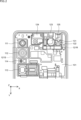
- FIG. 1 is a diagram illustrating an example of an internal configuration of an embodiment of an electronic device to which the present disclosure is applied.
- FIG. 2 is a diagram showing a detailed arrangement example of an upper space of the internal configuration of the electronic device shown in FIG. 1;
- FIG. 3 is a diagram showing an example of a cross-sectional configuration around the vibrating section in FIG. 2; 3 is a diagram showing an example of a cross-sectional configuration of the audio jack of FIG. 2.
- FIG. FIG. 6 is a diagram illustrating positioning in the XY directions in the upper space.
- FIG. 6 is a diagram illustrating positioning in the Z direction in the upper space. It is a figure explaining the details of the positioning of a vibrating part in the XY direction.
- FIG. 1 is a diagram illustrating an example of an internal configuration of an embodiment of an electronic device to which the present disclosure is applied.
- FIG. 2 is a diagram showing a detailed arrangement example of an upper space of the internal configuration of the electronic device shown in FIG. 1;
- FIG. 6 is a diagram illustrating details of positioning of the vibrating unit and the front camera in the Z direction. It is a figure which shows the example of arrangement
- 3 is a diagram showing an example of a cross-sectional configuration in the X direction including the rear camera and millimeter wave antenna section of FIG. 2.
- FIG. 1 is a diagram illustrating an example of the internal configuration of an embodiment of an electronic device to which the present disclosure is applied.
- the electronic device 10 is an electronic device such as a smartphone.
- the surface on which the display is installed is referred to as the "front”
- the surface opposite to the front is referred to as the "rear”.
- the rear side is referred to as the "front”.
- Figure 1 shows the internal structure of the housing as seen from the front.
- a main board 101 that is electrically connected to each part and a battery part 102 that supplies power to each part are arranged inside the casing of the electronic device 10.
- the space on the upper surface side within the housing (hereinafter also referred to as upper space) is referred to as the "upper surface”.
- the main board 101 is arranged in a space below the upper space within the housing (hereinafter also referred to as a lower space).
- the upper space can be said to be a space on the upper body side of the electronic device 10
- the lower space can be said to be a space on the lower body side of the electronic device 10.
- Various parts such as rear cameras 111 to 113, ranging sensor 114, millimeter wave antenna parts 121R and 121S, vibration part 122, front camera 123, top speaker 124, and audio jack 125 are arranged in the upper space inside the housing. , are connected to the main board 101.
- the rear cameras 111 to 113 are cameras provided on the back of the electronic device 10.
- the rear cameras 111 to 113 capture still images and videos.
- the rear camera 111 is configured with an ultra-wide-angle camera
- the rear camera 112 is configured with a wide-angle camera
- the rear camera 113 is configured with a telephoto camera.
- the distance sensor 114 is a sensor provided on the back of the electronic device 10.
- the ranging sensor 114 is configured with a ToF (Time of Flight) sensor.
- the millimeter wave antenna section 121R and the millimeter wave antenna section 121S are each configured with a millimeter wave module (millimeter wave antenna module) including an antenna for communicating using millimeter waves (MMW).
- the millimeter wave antenna section 121R is provided on the back surface of the electronic device 10.
- the millimeter wave antenna section 121S is located on the side surface of the electronic device 10 (the left side surface when the back surface is the reference surface). provided.
- the electronic device 10 is provided with a plurality of millimeter wave antennas arranged linearly in a predetermined direction, thereby increasing the reception sensitivity of communication using millimeter waves.
- the vibration unit 122 vibrates (the housing of) the electronic device 10.
- the vibrating section 122 is composed of a linear resonant actuator (LRA). By causing the vibration unit 122 to vibrate the housing, it is possible to notify the user of incoming calls, notifications, and the like.
- LRA linear resonant actuator
- the front camera 123 is a camera provided on the front of the electronic device 10.
- the front camera 123 allows the user using the electronic device 10 to take a picture of himself/herself.
- the top speaker 124 is a speaker provided on the top side of the electronic device 10.
- the top speaker 124 outputs sounds when playing content such as music and videos, a ringtone, the voice of the other party during a call, and the like.
- the audio jack 125 is a jack into which a plug at the end of a cable connected to earphones or headphones is inserted.
- the earphones or the like output the sound of content such as music or videos played by the electronic device 10 via a cable.
- an external card such as a SIM (Subscriber Identity Module) card or a memory card is attached to a card tray and connected.
- SIM Subscriber Identity Module
- One or more types of external cards can be connected to the connector 126.
- the electronic device 10 can read data from the external card and write data to the external card.
- the vibrating section 122 can be arranged in the upper space. That is, when adopting a configuration in which the connector 126 is mounted on the main board 101 and placed in the upper space within the housing of the electronic device 10 as an internal configuration different from the internal configuration shown in FIG. A configuration in which the vibrating section 122 is arranged in the lower space instead of the upper space is assumed.
- the connector 126 in order to maximize the mounting area of the main board 101, the connector 126 is moved to the lower space and the shape of the vibrating part 122 is appropriately shaped.
- the portion 122 can be placed in the upper space.
- FIG. 2 is a diagram showing a detailed example of the arrangement of the upper space of the internal configuration of the electronic device 10 of FIG. 1.
- the millimeter wave antenna section 121R, the vibration section 122, the front camera 123, the top speaker 124, and the audio jack 125 are arranged together at predetermined intervals. densely arranged.
- the vibrating section 122 and the front camera 123 side by side in the Y direction (vertical direction in the figure)
- the vibrating section 122, the front camera 123, the top speaker 124, and the audio jack 125 can be arranged in the Y direction.
- the sizes of the parts are approximately the same, and the arrangement of the five parts mentioned above is realized.
- the five components mentioned above are the millimeter wave antenna section 121R, the vibration section 122, the front camera 123, the top speaker 124, and the audio jack 125.
- a flexible printed circuit (FPC) 131 of the front camera 123 passes through the top surface of the vibrating unit 122 and is connected to the main board 101.
- the flexible substrate 131 has a substantially L-shape (inverted L-shape) extending from the Y direction to the X direction, and is connected to the main substrate 101 near the vibrating section 122 (on the left side in the figure).
- the flexible substrate 131 substantially L-shaped and connecting it near the vibrating section 122, components can be arranged closely.
- the vibrating section 122 can be placed close to the front camera 123. In order to bring the distance between the vibrating section 122 and the front camera 123 as close as possible, it is desirable to increase the angle at which the front camera 123 is installed.
- the position of the millimeter wave antenna section 121R can be brought as close as possible to the vibrating section 122.
- the shape of the flexible substrate 131 is such that it avoids the millimeter wave antenna section 121R.
- FIG. 3 is a diagram showing an example of a cross-sectional configuration around the vibrating section 122 shown in FIG. 2.
- the main housing 151, the main board 101, and the frame rear 152 are stacked and fixed with screws 161.
- the main board 101, the main casing 151, and the frame rear 152 each have a predetermined shape, and by stacking them, a space is formed within the casing, and the vibrating section 122 is fixed in the space.
- Frame rear 152 is configured as a part of the housing.
- a flexible board 131 of the front camera 123 passes through the top surface of the vibrating unit 122, and a buffer member 153 and a buffer member 154 are provided so as to sandwich a portion of the approximately L-shaped flexible board 131.
- the buffer member 153 is made of a cushioning material attached to the vibrating section 122 or the like.
- the buffer member 154 is made of a cushioning material attached to the frame rear 152.
- the flexible substrate 131 By sandwiching the flexible substrate 131 in the Z direction between the buffer members 153 and 154, the flexible substrate 131 can be vibrated in a configuration in which the vibration unit 122 and the front camera 123 are arranged side by side in the Y direction as shown in FIG. Even when passing through the top surface of the vibrating portion 122, the vibration by the vibrating portion 122 can be effectively transmitted.
- FIG. 4 is a diagram showing an example of the cross-sectional configuration of the audio jack 125 shown in FIG. 2. As shown in FIG. 4, the flexible board 132 of the audio jack 125 is connected to the front side of the main board 101.
- the space in which components can be placed on the back side of the main board 101 can be increased. Can be done. As a result, a space for arranging the millimeter-wave antenna section 121R is secured on the back side of the main board 101, and the millimeter-wave antenna section 121R is crowded together with the vibration section 122, front camera 123, top speaker 124, and audio jack 125. It can be placed as follows.
- the vibrating section 122 is attached to the main housing 151 with an adhesive tape 155, and then suppressed by the frame rear 152.
- the flexible substrate 131 of the front camera 123 passes through the top surface of the vibrating section 122, and the structure is such that the flexible substrate 131 of the front camera 123 is buffered and suppressed in the Z direction by the buffer members 153 and 154.
- the buffer member 154 is attached to the frame rear 152 with an adhesive tape 156.
- the front camera 123 is fixed to the frame rear 152 via a buffer member 157 such as a gasket.
- the rear cameras 111 to 113 and the distance measurement sensor 114 are arranged in the Y direction on the back side in the upper space of the housing, and the distance measurement sensor 114 is arranged on the left side in the Y direction. It has a configuration in which a millimeter wave antenna section 121S provided in a straight line is arranged adjacent to each other. These components (modules) generate a large amount of heat and are laid out with large heat sources adjacent to each other, so it is necessary to optimize the heat dissipation structure.
- FIG. 9 is a diagram showing an example of the arrangement of heat dissipation sheets in the upper space of the internal configuration of the electronic device 10.
- FIG. 9 shows the internal configuration of the electronic device 10, with parts such as the main board 101, rear cameras 111 to 113, ranging sensor 114, and millimeter wave antenna section 121S removed, and the position where the heat dissipation sheet 181 is placed. ing. As shown by the dotted area in the figure, one heat dissipation sheet 181 is arranged in a substantially L-shape from the left side surface to the bottom surface within the housing.
- the bottom surface here is a surface on which components such as the main board 101, rear cameras 111 to 113, and distance measurement sensor 114 are arranged.
- FIG. 10 is a diagram showing an example of a cross-sectional configuration in the X direction including the rear camera 112 and the millimeter wave antenna section 121S shown in FIGS. 1 and 2.
- a heat dissipation sheet 181 having a substantially L-shape is arranged for the rear camera 112 provided on the back side and the millimeter wave antenna section 121S provided on the left side.
- the heat dissipation structure is completed by one heat dissipation sheet 181 by serving not only the heat dissipation structure of the rear camera 112 but also the heat dissipation structure of the adjacent rear camera 112.
- the cross-sectional configuration example in FIG. 10 shows a cross-sectional configuration example of the rear camera 112 and the millimeter wave antenna section 121S, but as shown in FIG. and distance measuring sensor 114. That is, one heat dissipation sheet 181 serves not only as a heat dissipation structure for the millimeter wave antenna section 121S but also for the rear camera 111, the rear camera 112, and the distance measurement sensor 114. Note that in the configurations shown in FIGS. 9 and 10, the rear camera 113 adopts a heat dissipation structure different from the heat dissipation structure using the heat dissipation sheet 181 due to its structure. , depending on the structure of other cameras, it may be included in the heat dissipation structure using the heat dissipation sheet 181.
- the millimeter wave antenna section 121S is arranged on the side surface of the lower space instead of the side surface of the upper space as an internal configuration different from the internal configuration shown in FIG.
- the degree of freedom in the size and arrangement of the battery section 102 is limited.
- the degree of freedom in the size and arrangement of the battery section 102 can be increased in the lower space.
- the capacity of the battery section 102 can be increased by increasing its size.
- the electronic device 10 communicates using millimeter waves with the main board 101 located in the upper space, which is a space on a side different from the lower space on the side where the battery section 102 is arranged in the housing.
- a millimeter wave antenna section 121R is provided, a vibration section 122 for vibrating the housing, and a front camera 123 on the front side are provided.
- the millimeter wave antenna section 121R, the vibration section 122, and the front camera 123 are arranged in a line in the Y direction in the upper space.
- the millimeter wave antenna section 121R, the vibration section 122, the front camera 123, the top speaker 124, and the audio jack 125 are arranged together at predetermined intervals.
- the electronic device 10 in order to maximize the mounting area of the main board 101, the position of the connector 126 is moved from the main board 101 in the upper space to the lower space, and the millimeter wave antenna section 121R and The vibrating section 122, the front camera 123, the top speaker 124, and the audio jack 125 are arranged efficiently in the upper space.
- the electronic device 10 adopts a layout in which the vibrating section 122 and the front camera 123 are arranged side by side in the Y direction (vertical direction), which contributes to improving the efficiency of the layout. In this way, in the electronic device 10, components can be arranged more appropriately.
- the millimeter wave antenna section 121R, the vibration section 122, and the front camera 123 are arranged side by side in the Y direction in the upper space of the housing.
- Other parts may be placed instead. That is, in the upper space, the millimeter wave antenna section 121R, the vibrating section 122, and other components are arranged side by side in the Y direction.
- the other components include top speaker 124 or audio jack 125.
- the Y direction is a direction perpendicular to the X direction, where the direction in which the millimeter wave antenna section 121R is linearly arranged is the X direction.
- each of the rear cameras 111 to 113 and the ranging sensor 114 is an example of a sensor section, and in the electronic device 10, one or more sensor sections can be provided on the back side.
- the heat dissipation sheet 181 is arranged for at least some of the sensor sections together with the millimeter wave antenna section 121S on the left side.
- the vibrating section 122 has been described as being composed of a linear resonant actuator (LRA), other methods such as an eccentric motor (ERM) or a method using a piezo element may be adopted. do not have.
- LRA linear resonant actuator
- ELM eccentric motor
- piezo element a method using a piezo element
- the electronic device 10 is not limited to a smartphone, but may be a small portable device such as a tablet terminal, a mobile phone, a wearable device, or a notebook PC. Furthermore, the electronic device 10 may be an independent device or an internal block constituting one device.
- connection means electrical connection.
- component refers to a module (module component) that combines several parts into one according to function and location, so “component” described in this specification may be read as “module”. I don't mind.
- the present disclosure can have the following configuration.
- a main board disposed in a second space that is a space on a side different from the first space on the side where the battery section is disposed within the casing; a first antenna section for communicating using millimeter waves; a vibrating section that vibrates the housing;
- the first antenna section is arranged linearly in a first direction on the same plane as the main board in the second space, In the second space, the first antenna section, the vibrating section, and other parts excluding the first antenna section and the vibrating section are arranged in a second direction perpendicular to the first direction.
- Electronic devices arranged side by side.
- the first antenna section, the vibration section, the front camera, the speaker, and the audio jack are arranged at predetermined intervals.
- the electronic device according to (1) above which is arranged as follows. (3) The other component is the front camera, The electronic device according to (2), wherein the first antenna section, the vibration section, and the front camera are arranged in this order in the second direction, which is the direction away from the battery section. (4) The electronic device according to (3), wherein the flexible board of the front camera passes through the top surface of the vibrating section and is connected to the main board.
- the flexible board has a substantially L-shape extending from the second direction to the first direction on the same plane as the main board, and is connected to the main board near the vibrating section.
- the flexible substrate is sandwiched between buffer members on the top surface of the vibrating section in a third direction of an axis perpendicular to a plane including the axis in the first direction and the axis in the second direction. 4) or the electronic device described in (5).
- the first surface is a surface on the back side
- the second antenna section is arranged on a side surface of the housing in the second space,
- the sensor section is arranged on a third surface of the second space that is a surface on a side where the main board is arranged,
- the electronic device according to (1) further comprising a heat dissipation member that transfers heat from the second antenna section and the sensor section.
- the heat radiating member is a single heat radiating sheet having a substantially L-shape, and is arranged from a side surface of the housing to the third surface.
- the heat dissipation sheet is arranged for at least some of the sensor parts when a plurality of the sensor parts are arranged.
- the sensor section is a rear camera or a distance measurement sensor.
- the second space is a space on the upper end side of the housing, The electronic device according to (1), wherein the first space is a space closer to the lower end of the housing than the second space.
Landscapes
- Engineering & Computer Science (AREA)
- Signal Processing (AREA)
- Support Of Aerials (AREA)
- Studio Devices (AREA)
Priority Applications (2)
| Application Number | Priority Date | Filing Date | Title |
|---|---|---|---|
| CN202380037880.7A CN119137807A (zh) | 2022-05-10 | 2023-04-24 | 电子设备 |
| JP2024520356A JPWO2023218923A1 (https=) | 2022-05-10 | 2023-04-24 |
Applications Claiming Priority (2)
| Application Number | Priority Date | Filing Date | Title |
|---|---|---|---|
| JP2022-077370 | 2022-05-10 | ||
| JP2022077370 | 2022-05-10 |
Publications (1)
| Publication Number | Publication Date |
|---|---|
| WO2023218923A1 true WO2023218923A1 (ja) | 2023-11-16 |
Family
ID=88730364
Family Applications (1)
| Application Number | Title | Priority Date | Filing Date |
|---|---|---|---|
| PCT/JP2023/016069 Ceased WO2023218923A1 (ja) | 2022-05-10 | 2023-04-24 | 電子機器 |
Country Status (3)
| Country | Link |
|---|---|
| JP (1) | JPWO2023218923A1 (https=) |
| CN (1) | CN119137807A (https=) |
| WO (1) | WO2023218923A1 (https=) |
Cited By (1)
| Publication number | Priority date | Publication date | Assignee | Title |
|---|---|---|---|---|
| CN119172462A (zh) * | 2024-11-07 | 2024-12-20 | 荣耀终端有限公司 | 电子设备和天线组件 |
Citations (5)
| Publication number | Priority date | Publication date | Assignee | Title |
|---|---|---|---|---|
| JP2002223082A (ja) * | 2001-01-29 | 2002-08-09 | Olympus Optical Co Ltd | 電気機器 |
| JP2009290600A (ja) * | 2008-05-29 | 2009-12-10 | Kyocera Corp | アンテナ素子及び無線通信装置 |
| EP2632121A1 (en) * | 2012-02-23 | 2013-08-28 | Samsung Electronics Co., Ltd | Portable Terminal |
| US20150098174A1 (en) * | 2013-10-09 | 2015-04-09 | Samsung Electronics Co., Ltd. | Electronic device with curved display module |
| US10389007B1 (en) * | 2018-06-11 | 2019-08-20 | Lg Electronics Inc. | Mobile terminal |
-
2023
- 2023-04-24 WO PCT/JP2023/016069 patent/WO2023218923A1/ja not_active Ceased
- 2023-04-24 CN CN202380037880.7A patent/CN119137807A/zh not_active Withdrawn
- 2023-04-24 JP JP2024520356A patent/JPWO2023218923A1/ja active Pending
Patent Citations (5)
| Publication number | Priority date | Publication date | Assignee | Title |
|---|---|---|---|---|
| JP2002223082A (ja) * | 2001-01-29 | 2002-08-09 | Olympus Optical Co Ltd | 電気機器 |
| JP2009290600A (ja) * | 2008-05-29 | 2009-12-10 | Kyocera Corp | アンテナ素子及び無線通信装置 |
| EP2632121A1 (en) * | 2012-02-23 | 2013-08-28 | Samsung Electronics Co., Ltd | Portable Terminal |
| US20150098174A1 (en) * | 2013-10-09 | 2015-04-09 | Samsung Electronics Co., Ltd. | Electronic device with curved display module |
| US10389007B1 (en) * | 2018-06-11 | 2019-08-20 | Lg Electronics Inc. | Mobile terminal |
Cited By (1)
| Publication number | Priority date | Publication date | Assignee | Title |
|---|---|---|---|---|
| CN119172462A (zh) * | 2024-11-07 | 2024-12-20 | 荣耀终端有限公司 | 电子设备和天线组件 |
Also Published As
| Publication number | Publication date |
|---|---|
| CN119137807A (zh) | 2024-12-13 |
| JPWO2023218923A1 (https=) | 2023-11-16 |
Similar Documents
| Publication | Publication Date | Title |
|---|---|---|
| US10687146B2 (en) | Speaker with flex circuit acoustic radiator | |
| AU2017390082B2 (en) | Capacitive sensing of a moving-coil structure with an inset plate | |
| US7953461B2 (en) | Mobile terminal and speaker | |
| JP5102876B2 (ja) | スピーカ組立体が埋設されたpcb | |
| US8532722B2 (en) | Folded flex assembly for personal media device | |
| EP1827057A2 (en) | Display and speaker module | |
| CN103988524B (zh) | 音响发生器、音响发生装置以及电子设备 | |
| KR102919981B1 (ko) | 안테나 패턴을 포함하는 플렉서블 어셈블리 및 이를 포함하는 전자 장치 | |
| EP4096367A1 (en) | Electronic device comprising printed circuit board | |
| KR101572828B1 (ko) | 휴대 단말기용 스피커 장치 | |
| KR102889352B1 (ko) | 안테나 및 인쇄회로기판을 포함하는 전자 장치 | |
| US8260343B2 (en) | Electronic devices including vertically mounted loudspeakers and related assemblies and methods | |
| KR20210011144A (ko) | 기판 조립체를 포함하는 전자 장치 | |
| US8301188B2 (en) | Electronic devices including substrate mounted acoustic actuators and related methods and mobile radiotelephones | |
| WO2023218923A1 (ja) | 電子機器 | |
| CN213126091U (zh) | 一种电子设备 | |
| CN212307075U (zh) | 电子设备组件及其保护壳 | |
| CN101494670B (zh) | 可携式电子装置 | |
| US20250373921A1 (en) | Camera assembly and electronic device | |
| EP4614276A1 (en) | Electronic device comprising speaker module | |
| WO2025145940A9 (zh) | 电子设备 | |
| CN119653001A (zh) | 电子设备及其振动组件 | |
| TWM668716U (zh) | 電子裝置 | |
| CN121691995A (zh) | 一种mems芯片、mems扬声器及电子设备 | |
| CN119698850A (zh) | 电子设备 |
Legal Events
| Date | Code | Title | Description |
|---|---|---|---|
| 121 | Ep: the epo has been informed by wipo that ep was designated in this application |
Ref document number: 23803405 Country of ref document: EP Kind code of ref document: A1 |
|
| WWE | Wipo information: entry into national phase |
Ref document number: 2024520356 Country of ref document: JP |
|
| WWE | Wipo information: entry into national phase |
Ref document number: 202380037880.7 Country of ref document: CN |
|
| NENP | Non-entry into the national phase |
Ref country code: DE |
|
| 122 | Ep: pct application non-entry in european phase |
Ref document number: 23803405 Country of ref document: EP Kind code of ref document: A1 |