WO2023218923A1 - Electronic device - Google Patents
Electronic device Download PDFInfo
- Publication number
- WO2023218923A1 WO2023218923A1 PCT/JP2023/016069 JP2023016069W WO2023218923A1 WO 2023218923 A1 WO2023218923 A1 WO 2023218923A1 JP 2023016069 W JP2023016069 W JP 2023016069W WO 2023218923 A1 WO2023218923 A1 WO 2023218923A1
- Authority
- WO
- WIPO (PCT)
- Prior art keywords
- space
- section
- electronic device
- main board
- antenna section
- Prior art date
Links
- 239000000758 substrate Substances 0.000 claims abstract description 15
- 230000017525 heat dissipation Effects 0.000 claims description 33
- 238000005259 measurement Methods 0.000 claims description 6
- 238000004891 communication Methods 0.000 abstract description 7
- 238000010586 diagram Methods 0.000 description 14
- 239000002390 adhesive tape Substances 0.000 description 3
- 238000000034 method Methods 0.000 description 3
- 239000000463 material Substances 0.000 description 2
- 238000010295 mobile communication Methods 0.000 description 2
- 230000000694 effects Effects 0.000 description 1
- 230000001151 other effect Effects 0.000 description 1
- 230000002093 peripheral effect Effects 0.000 description 1
- 230000035945 sensitivity Effects 0.000 description 1
Images


Classifications
-
- H—ELECTRICITY
- H01—ELECTRIC ELEMENTS
- H01Q—ANTENNAS, i.e. RADIO AERIALS
- H01Q1/00—Details of, or arrangements associated with, antennas
- H01Q1/12—Supports; Mounting means
- H01Q1/22—Supports; Mounting means by structural association with other equipment or articles
- H01Q1/24—Supports; Mounting means by structural association with other equipment or articles with receiving set
-
- H—ELECTRICITY
- H01—ELECTRIC ELEMENTS
- H01Q—ANTENNAS, i.e. RADIO AERIALS
- H01Q1/00—Details of, or arrangements associated with, antennas
- H01Q1/52—Means for reducing coupling between antennas; Means for reducing coupling between an antenna and another structure
-
- H—ELECTRICITY
- H01—ELECTRIC ELEMENTS
- H01Q—ANTENNAS, i.e. RADIO AERIALS
- H01Q21/00—Antenna arrays or systems
- H01Q21/28—Combinations of substantially independent non-interacting antenna units or systems
-
- H—ELECTRICITY
- H04—ELECTRIC COMMUNICATION TECHNIQUE
- H04M—TELEPHONIC COMMUNICATION
- H04M1/00—Substation equipment, e.g. for use by subscribers
- H04M1/02—Constructional features of telephone sets
Definitions
- the present disclosure relates to an electronic device, and particularly to an electronic device that allows components to be more appropriately arranged.
- millimeter waves such as 28 GHz and 39 GHz
- millimeter waves can increase the amount of information transmitted compared to ultra-high frequency waves, they have high straightness and have a narrow angular range in which communication can be performed. Therefore, electronic devices that perform communication using millimeter waves may support multiple directions by being equipped with a plurality of millimeter wave antenna modules.
- the present disclosure has been made in view of this situation, and is intended to enable components to be more appropriately arranged.
- An electronic device communicates using millimeter waves with a main board disposed in a second space that is a space on a side different from a first space on a side where a battery section is disposed in a housing.
- a first antenna section for vibrating the housing; and a vibration section for vibrating the housing, the first antenna section being arranged in a straight line in a first direction on the same plane as the main board in the second space.
- the first antenna section, the vibrating section, and other components other than the first antenna section and the vibrating section are arranged in the first direction.
- These electronic devices are arranged side by side in a second orthogonal direction.
- a main board disposed in a second space that is a space on a side different from the first space on the side where the battery section is disposed in the housing, and a communication device using millimeter waves.
- a first antenna section for performing this and a vibration section for vibrating the housing are provided.
- the first antenna section is arranged linearly in a first direction on the same plane as the main board in the second space, and the first antenna section and The vibrating section, the first antenna section, and other components other than the vibrating section are arranged side by side in a second direction orthogonal to the first direction.
- FIG. 1 is a diagram illustrating an example of an internal configuration of an embodiment of an electronic device to which the present disclosure is applied.
- FIG. 2 is a diagram showing a detailed arrangement example of an upper space of the internal configuration of the electronic device shown in FIG. 1;
- FIG. 3 is a diagram showing an example of a cross-sectional configuration around the vibrating section in FIG. 2; 3 is a diagram showing an example of a cross-sectional configuration of the audio jack of FIG. 2.
- FIG. FIG. 6 is a diagram illustrating positioning in the XY directions in the upper space.
- FIG. 6 is a diagram illustrating positioning in the Z direction in the upper space. It is a figure explaining the details of the positioning of a vibrating part in the XY direction.
- FIG. 1 is a diagram illustrating an example of an internal configuration of an embodiment of an electronic device to which the present disclosure is applied.
- FIG. 2 is a diagram showing a detailed arrangement example of an upper space of the internal configuration of the electronic device shown in FIG. 1;
- FIG. 6 is a diagram illustrating details of positioning of the vibrating unit and the front camera in the Z direction. It is a figure which shows the example of arrangement
- 3 is a diagram showing an example of a cross-sectional configuration in the X direction including the rear camera and millimeter wave antenna section of FIG. 2.
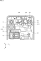
- FIG. 1 is a diagram illustrating an example of the internal configuration of an embodiment of an electronic device to which the present disclosure is applied.
- the electronic device 10 is an electronic device such as a smartphone.
- the surface on which the display is installed is referred to as the "front”
- the surface opposite to the front is referred to as the "rear”.
- the rear side is referred to as the "front”.
- Figure 1 shows the internal structure of the housing as seen from the front.
- a main board 101 that is electrically connected to each part and a battery part 102 that supplies power to each part are arranged inside the casing of the electronic device 10.
- the space on the upper surface side within the housing (hereinafter also referred to as upper space) is referred to as the "upper surface”.
- the main board 101 is arranged in a space below the upper space within the housing (hereinafter also referred to as a lower space).
- the upper space can be said to be a space on the upper body side of the electronic device 10
- the lower space can be said to be a space on the lower body side of the electronic device 10.
- Various parts such as rear cameras 111 to 113, ranging sensor 114, millimeter wave antenna parts 121R and 121S, vibration part 122, front camera 123, top speaker 124, and audio jack 125 are arranged in the upper space inside the housing. , are connected to the main board 101.
- the rear cameras 111 to 113 are cameras provided on the back of the electronic device 10.
- the rear cameras 111 to 113 capture still images and videos.
- the rear camera 111 is configured with an ultra-wide-angle camera
- the rear camera 112 is configured with a wide-angle camera
- the rear camera 113 is configured with a telephoto camera.
- the distance sensor 114 is a sensor provided on the back of the electronic device 10.
- the ranging sensor 114 is configured with a ToF (Time of Flight) sensor.
- the millimeter wave antenna section 121R and the millimeter wave antenna section 121S are each configured with a millimeter wave module (millimeter wave antenna module) including an antenna for communicating using millimeter waves (MMW).
- the millimeter wave antenna section 121R is provided on the back surface of the electronic device 10.
- the millimeter wave antenna section 121S is located on the side surface of the electronic device 10 (the left side surface when the back surface is the reference surface). provided.
- the electronic device 10 is provided with a plurality of millimeter wave antennas arranged linearly in a predetermined direction, thereby increasing the reception sensitivity of communication using millimeter waves.
- the vibration unit 122 vibrates (the housing of) the electronic device 10.
- the vibrating section 122 is composed of a linear resonant actuator (LRA). By causing the vibration unit 122 to vibrate the housing, it is possible to notify the user of incoming calls, notifications, and the like.
- LRA linear resonant actuator
- the front camera 123 is a camera provided on the front of the electronic device 10.
- the front camera 123 allows the user using the electronic device 10 to take a picture of himself/herself.
- the top speaker 124 is a speaker provided on the top side of the electronic device 10.
- the top speaker 124 outputs sounds when playing content such as music and videos, a ringtone, the voice of the other party during a call, and the like.
- the audio jack 125 is a jack into which a plug at the end of a cable connected to earphones or headphones is inserted.
- the earphones or the like output the sound of content such as music or videos played by the electronic device 10 via a cable.
- an external card such as a SIM (Subscriber Identity Module) card or a memory card is attached to a card tray and connected.
- SIM Subscriber Identity Module
- One or more types of external cards can be connected to the connector 126.
- the electronic device 10 can read data from the external card and write data to the external card.
- the vibrating section 122 can be arranged in the upper space. That is, when adopting a configuration in which the connector 126 is mounted on the main board 101 and placed in the upper space within the housing of the electronic device 10 as an internal configuration different from the internal configuration shown in FIG. A configuration in which the vibrating section 122 is arranged in the lower space instead of the upper space is assumed.
- the connector 126 in order to maximize the mounting area of the main board 101, the connector 126 is moved to the lower space and the shape of the vibrating part 122 is appropriately shaped.
- the portion 122 can be placed in the upper space.
- FIG. 2 is a diagram showing a detailed example of the arrangement of the upper space of the internal configuration of the electronic device 10 of FIG. 1.
- the millimeter wave antenna section 121R, the vibration section 122, the front camera 123, the top speaker 124, and the audio jack 125 are arranged together at predetermined intervals. densely arranged.
- the vibrating section 122 and the front camera 123 side by side in the Y direction (vertical direction in the figure)
- the vibrating section 122, the front camera 123, the top speaker 124, and the audio jack 125 can be arranged in the Y direction.
- the sizes of the parts are approximately the same, and the arrangement of the five parts mentioned above is realized.
- the five components mentioned above are the millimeter wave antenna section 121R, the vibration section 122, the front camera 123, the top speaker 124, and the audio jack 125.
- a flexible printed circuit (FPC) 131 of the front camera 123 passes through the top surface of the vibrating unit 122 and is connected to the main board 101.
- the flexible substrate 131 has a substantially L-shape (inverted L-shape) extending from the Y direction to the X direction, and is connected to the main substrate 101 near the vibrating section 122 (on the left side in the figure).
- the flexible substrate 131 substantially L-shaped and connecting it near the vibrating section 122, components can be arranged closely.
- the vibrating section 122 can be placed close to the front camera 123. In order to bring the distance between the vibrating section 122 and the front camera 123 as close as possible, it is desirable to increase the angle at which the front camera 123 is installed.
- the position of the millimeter wave antenna section 121R can be brought as close as possible to the vibrating section 122.
- the shape of the flexible substrate 131 is such that it avoids the millimeter wave antenna section 121R.
- FIG. 3 is a diagram showing an example of a cross-sectional configuration around the vibrating section 122 shown in FIG. 2.
- the main housing 151, the main board 101, and the frame rear 152 are stacked and fixed with screws 161.
- the main board 101, the main casing 151, and the frame rear 152 each have a predetermined shape, and by stacking them, a space is formed within the casing, and the vibrating section 122 is fixed in the space.
- Frame rear 152 is configured as a part of the housing.
- a flexible board 131 of the front camera 123 passes through the top surface of the vibrating unit 122, and a buffer member 153 and a buffer member 154 are provided so as to sandwich a portion of the approximately L-shaped flexible board 131.
- the buffer member 153 is made of a cushioning material attached to the vibrating section 122 or the like.
- the buffer member 154 is made of a cushioning material attached to the frame rear 152.
- the flexible substrate 131 By sandwiching the flexible substrate 131 in the Z direction between the buffer members 153 and 154, the flexible substrate 131 can be vibrated in a configuration in which the vibration unit 122 and the front camera 123 are arranged side by side in the Y direction as shown in FIG. Even when passing through the top surface of the vibrating portion 122, the vibration by the vibrating portion 122 can be effectively transmitted.
- FIG. 4 is a diagram showing an example of the cross-sectional configuration of the audio jack 125 shown in FIG. 2. As shown in FIG. 4, the flexible board 132 of the audio jack 125 is connected to the front side of the main board 101.
- the space in which components can be placed on the back side of the main board 101 can be increased. Can be done. As a result, a space for arranging the millimeter-wave antenna section 121R is secured on the back side of the main board 101, and the millimeter-wave antenna section 121R is crowded together with the vibration section 122, front camera 123, top speaker 124, and audio jack 125. It can be placed as follows.
- the vibrating section 122 is attached to the main housing 151 with an adhesive tape 155, and then suppressed by the frame rear 152.
- the flexible substrate 131 of the front camera 123 passes through the top surface of the vibrating section 122, and the structure is such that the flexible substrate 131 of the front camera 123 is buffered and suppressed in the Z direction by the buffer members 153 and 154.
- the buffer member 154 is attached to the frame rear 152 with an adhesive tape 156.
- the front camera 123 is fixed to the frame rear 152 via a buffer member 157 such as a gasket.
- the rear cameras 111 to 113 and the distance measurement sensor 114 are arranged in the Y direction on the back side in the upper space of the housing, and the distance measurement sensor 114 is arranged on the left side in the Y direction. It has a configuration in which a millimeter wave antenna section 121S provided in a straight line is arranged adjacent to each other. These components (modules) generate a large amount of heat and are laid out with large heat sources adjacent to each other, so it is necessary to optimize the heat dissipation structure.
- FIG. 9 is a diagram showing an example of the arrangement of heat dissipation sheets in the upper space of the internal configuration of the electronic device 10.
- FIG. 9 shows the internal configuration of the electronic device 10, with parts such as the main board 101, rear cameras 111 to 113, ranging sensor 114, and millimeter wave antenna section 121S removed, and the position where the heat dissipation sheet 181 is placed. ing. As shown by the dotted area in the figure, one heat dissipation sheet 181 is arranged in a substantially L-shape from the left side surface to the bottom surface within the housing.
- the bottom surface here is a surface on which components such as the main board 101, rear cameras 111 to 113, and distance measurement sensor 114 are arranged.
- FIG. 10 is a diagram showing an example of a cross-sectional configuration in the X direction including the rear camera 112 and the millimeter wave antenna section 121S shown in FIGS. 1 and 2.
- a heat dissipation sheet 181 having a substantially L-shape is arranged for the rear camera 112 provided on the back side and the millimeter wave antenna section 121S provided on the left side.
- the heat dissipation structure is completed by one heat dissipation sheet 181 by serving not only the heat dissipation structure of the rear camera 112 but also the heat dissipation structure of the adjacent rear camera 112.
- the cross-sectional configuration example in FIG. 10 shows a cross-sectional configuration example of the rear camera 112 and the millimeter wave antenna section 121S, but as shown in FIG. and distance measuring sensor 114. That is, one heat dissipation sheet 181 serves not only as a heat dissipation structure for the millimeter wave antenna section 121S but also for the rear camera 111, the rear camera 112, and the distance measurement sensor 114. Note that in the configurations shown in FIGS. 9 and 10, the rear camera 113 adopts a heat dissipation structure different from the heat dissipation structure using the heat dissipation sheet 181 due to its structure. , depending on the structure of other cameras, it may be included in the heat dissipation structure using the heat dissipation sheet 181.
- the millimeter wave antenna section 121S is arranged on the side surface of the lower space instead of the side surface of the upper space as an internal configuration different from the internal configuration shown in FIG.
- the degree of freedom in the size and arrangement of the battery section 102 is limited.
- the degree of freedom in the size and arrangement of the battery section 102 can be increased in the lower space.
- the capacity of the battery section 102 can be increased by increasing its size.
- the electronic device 10 communicates using millimeter waves with the main board 101 located in the upper space, which is a space on a side different from the lower space on the side where the battery section 102 is arranged in the housing.
- a millimeter wave antenna section 121R is provided, a vibration section 122 for vibrating the housing, and a front camera 123 on the front side are provided.
- the millimeter wave antenna section 121R, the vibration section 122, and the front camera 123 are arranged in a line in the Y direction in the upper space.
- the millimeter wave antenna section 121R, the vibration section 122, the front camera 123, the top speaker 124, and the audio jack 125 are arranged together at predetermined intervals.
- the electronic device 10 in order to maximize the mounting area of the main board 101, the position of the connector 126 is moved from the main board 101 in the upper space to the lower space, and the millimeter wave antenna section 121R and The vibrating section 122, the front camera 123, the top speaker 124, and the audio jack 125 are arranged efficiently in the upper space.
- the electronic device 10 adopts a layout in which the vibrating section 122 and the front camera 123 are arranged side by side in the Y direction (vertical direction), which contributes to improving the efficiency of the layout. In this way, in the electronic device 10, components can be arranged more appropriately.
- the millimeter wave antenna section 121R, the vibration section 122, and the front camera 123 are arranged side by side in the Y direction in the upper space of the housing.
- Other parts may be placed instead. That is, in the upper space, the millimeter wave antenna section 121R, the vibrating section 122, and other components are arranged side by side in the Y direction.
- the other components include top speaker 124 or audio jack 125.
- the Y direction is a direction perpendicular to the X direction, where the direction in which the millimeter wave antenna section 121R is linearly arranged is the X direction.
- each of the rear cameras 111 to 113 and the ranging sensor 114 is an example of a sensor section, and in the electronic device 10, one or more sensor sections can be provided on the back side.
- the heat dissipation sheet 181 is arranged for at least some of the sensor sections together with the millimeter wave antenna section 121S on the left side.
- the vibrating section 122 has been described as being composed of a linear resonant actuator (LRA), other methods such as an eccentric motor (ERM) or a method using a piezo element may be adopted. do not have.
- LRA linear resonant actuator
- ELM eccentric motor
- piezo element a method using a piezo element
- the electronic device 10 is not limited to a smartphone, but may be a small portable device such as a tablet terminal, a mobile phone, a wearable device, or a notebook PC. Furthermore, the electronic device 10 may be an independent device or an internal block constituting one device.
- connection means electrical connection.
- component refers to a module (module component) that combines several parts into one according to function and location, so “component” described in this specification may be read as “module”. I don't mind.
- the present disclosure can have the following configuration.
- a main board disposed in a second space that is a space on a side different from the first space on the side where the battery section is disposed within the casing; a first antenna section for communicating using millimeter waves; a vibrating section that vibrates the housing;
- the first antenna section is arranged linearly in a first direction on the same plane as the main board in the second space, In the second space, the first antenna section, the vibrating section, and other parts excluding the first antenna section and the vibrating section are arranged in a second direction perpendicular to the first direction.
- Electronic devices arranged side by side.
- the first antenna section, the vibration section, the front camera, the speaker, and the audio jack are arranged at predetermined intervals.
- the electronic device according to (1) above which is arranged as follows. (3) The other component is the front camera, The electronic device according to (2), wherein the first antenna section, the vibration section, and the front camera are arranged in this order in the second direction, which is the direction away from the battery section. (4) The electronic device according to (3), wherein the flexible board of the front camera passes through the top surface of the vibrating section and is connected to the main board.
- the flexible board has a substantially L-shape extending from the second direction to the first direction on the same plane as the main board, and is connected to the main board near the vibrating section.
- the flexible substrate is sandwiched between buffer members on the top surface of the vibrating section in a third direction of an axis perpendicular to a plane including the axis in the first direction and the axis in the second direction. 4) or the electronic device described in (5).
- the first surface is a surface on the back side
- the second antenna section is arranged on a side surface of the housing in the second space,
- the sensor section is arranged on a third surface of the second space that is a surface on a side where the main board is arranged,
- the electronic device according to (1) further comprising a heat dissipation member that transfers heat from the second antenna section and the sensor section.
- the heat radiating member is a single heat radiating sheet having a substantially L-shape, and is arranged from a side surface of the housing to the third surface.
- the heat dissipation sheet is arranged for at least some of the sensor parts when a plurality of the sensor parts are arranged.
- the sensor section is a rear camera or a distance measurement sensor.
- the second space is a space on the upper end side of the housing, The electronic device according to (1), wherein the first space is a space closer to the lower end of the housing than the second space.
Abstract
The present disclosure relates to electronic equipment configured such that a component can be more appropriately disposed. Provided is electronic equipment comprising a main substrate that is disposed in a second space within a housing, the second space being toward a different side of the housing from a first space toward where a battery part is disposed, a first antenna unit that is for performing communication using millimeter waves, and a vibration unit that vibrates the housing, wherein: the first antenna unit is disposed in a linear manner in a first direction on the same plane as the main substrate in the second space; and the first antenna unit, the vibration unit, and other components other than the first antenna unit and the vibration unit are disposed in the second space so as to be lined up in a second direction, which is perpendicular to the first direction. The present disclosure can be applied to, for example, the internal structure of a smartphone.
Description
本開示は、電子機器に関し、特に、より適切に部品を配置することができるようにした電子機器に関する。
The present disclosure relates to an electronic device, and particularly to an electronic device that allows components to be more appropriately arranged.
近年、第5世代移動体通信システム(5G:5th Generation Mobile Communication System)について各種検討がされている。例えば、同移動体通信システムでは、28GHzや39GHzといったミリ波と呼ばれる周波数の無線信号(以下、単に「ミリ波」ともいう)を用いた通信が利用可能である(例えば特許文献1参照)。
In recent years, various studies have been conducted regarding the 5th Generation Mobile Communication System (5G). For example, in this mobile communication system, communication using radio signals at frequencies called millimeter waves (hereinafter also simply referred to as "millimeter waves") such as 28 GHz and 39 GHz can be used (see, for example, Patent Document 1).
ミリ波は、極超短波と比べて伝送される情報の量を増加させることが可能となる一方で、直進性が高く通信可能な角度範囲が狭い。そのため、ミリ波を用いた通信を行う電子機器では、複数のミリ波用アンテナモジュールを搭載することで複数方向に対応する場合がある。
While millimeter waves can increase the amount of information transmitted compared to ultra-high frequency waves, they have high straightness and have a narrow angular range in which communication can be performed. Therefore, electronic devices that perform communication using millimeter waves may support multiple directions by being equipped with a plurality of millimeter wave antenna modules.
ミリ波を用いた通信を行う電子機器の筐体内には、複数のミリ波用アンテナモジュールを含む多数の部品を配置する必要があるが、配置可能な空間が限られているため、適切に部品を配置することが求められる。
It is necessary to place a large number of components, including multiple millimeter-wave antenna modules, inside the housing of an electronic device that communicates using millimeter waves, but since the space available for placement is limited, it is necessary to place the components appropriately. is required to be placed.
本開示はこのような状況に鑑みてなされたものであり、より適切に部品を配置することができるようにするものである。
The present disclosure has been made in view of this situation, and is intended to enable components to be more appropriately arranged.
本開示の一側面の電子機器は、筐体内でバッテリ部を配置する側の第1の空間と異なる側の空間である第2の空間に配置されるメイン基板と、ミリ波を用いた通信を行うための第1のアンテナ部と、前記筐体を振動させる振動部とを備え、前記第1のアンテナ部は、前記第2の空間における前記メイン基板と同一平面上で第1の方向に直線状に配置され、前記第2の空間において、前記第1のアンテナ部と、前記振動部と、前記第1のアンテナ部及び前記振動部を除いた他の部品とが、前記第1の方向と直交する第2の方向に並んで配置される電子機器である。
An electronic device according to one aspect of the present disclosure communicates using millimeter waves with a main board disposed in a second space that is a space on a side different from a first space on a side where a battery section is disposed in a housing. a first antenna section for vibrating the housing; and a vibration section for vibrating the housing, the first antenna section being arranged in a straight line in a first direction on the same plane as the main board in the second space. In the second space, the first antenna section, the vibrating section, and other components other than the first antenna section and the vibrating section are arranged in the first direction. These electronic devices are arranged side by side in a second orthogonal direction.
本開示の一側面の電子機器においては、筐体内でバッテリ部を配置する側の第1の空間と異なる側の空間である第2の空間に配置されるメイン基板と、ミリ波を用いた通信を行うための第1のアンテナ部と、前記筐体を振動させる振動部とが設けられる。また、前記第1のアンテナ部が、前記第2の空間における前記メイン基板と同一平面上で第1の方向に直線状に配置され、前記第2の空間において、前記第1のアンテナ部と、前記振動部と、前記第1のアンテナ部及び前記振動部を除いた他の部品とが、前記第1の方向と直交する第2の方向に並んで配置される。
In the electronic device according to one aspect of the present disclosure, a main board disposed in a second space that is a space on a side different from the first space on the side where the battery section is disposed in the housing, and a communication device using millimeter waves. A first antenna section for performing this and a vibration section for vibrating the housing are provided. The first antenna section is arranged linearly in a first direction on the same plane as the main board in the second space, and the first antenna section and The vibrating section, the first antenna section, and other components other than the vibrating section are arranged side by side in a second direction orthogonal to the first direction.
<機器の内部構成>
図1は、本開示を適用した電子機器の一実施の形態の内部構成例を示す図である。 <Internal configuration of the device>
FIG. 1 is a diagram illustrating an example of the internal configuration of an embodiment of an electronic device to which the present disclosure is applied.
図1は、本開示を適用した電子機器の一実施の形態の内部構成例を示す図である。 <Internal configuration of the device>
FIG. 1 is a diagram illustrating an example of the internal configuration of an embodiment of an electronic device to which the present disclosure is applied.
図1において、電子機器10は、スマートフォン等の電子機器である。電子機器10を構成する外観面のうち、ディスプレイが設けられる面を「前面」といい、前面と反対側の面を「背面」というとき、フレームリア等の背面側の部品を取り外して、背面側から見た筐体内の構造を、図1に示している。
In FIG. 1, the electronic device 10 is an electronic device such as a smartphone. Of the external surfaces that make up the electronic device 10, the surface on which the display is installed is referred to as the "front", and the surface opposite to the front is referred to as the "rear".When parts on the rear side such as the frame rear are removed, the rear side is referred to as the "front". Figure 1 shows the internal structure of the housing as seen from the front.
図1に示すように、電子機器10の筐体内には、各部に電気的に接続されたメイン基板101と、各部に電力を供給するバッテリ部102とが配置される。電子機器10を構成する外観面のうち、前面と背面に対する上端側の面を「上面」といい、下端側の面を「下面」というとき、筐体内の上面側の空間(以下、上側空間ともいう)にメイン基板101が配置され、筐体内の上側空間よりも下面側の空間(以下、下側空間ともいう)にバッテリ部102が配置される。換言すれば、上側空間は、電子機器10の上半身側の空間で、下側空間は、電子機器10の下半身側の空間であるとも言える。
As shown in FIG. 1, a main board 101 that is electrically connected to each part and a battery part 102 that supplies power to each part are arranged inside the casing of the electronic device 10. Of the external surfaces that make up the electronic device 10, when the surface on the upper end side with respect to the front and rear surfaces is referred to as the "upper surface" and the surface on the lower end side as the "lower surface", the space on the upper surface side within the housing (hereinafter also referred to as upper space) is referred to as the "upper surface". The main board 101 is arranged in a space below the upper space within the housing (hereinafter also referred to as a lower space). In other words, the upper space can be said to be a space on the upper body side of the electronic device 10, and the lower space can be said to be a space on the lower body side of the electronic device 10.
筐体内の上側空間には、リアカメラ111乃至113、測距センサ114、ミリ波アンテナ部121R,121S、振動部122、フロントカメラ123、トップスピーカ124、及びオーディオジャック125等の各種部品が配置され、メイン基板101に接続されている。
Various parts such as rear cameras 111 to 113, ranging sensor 114, millimeter wave antenna parts 121R and 121S, vibration part 122, front camera 123, top speaker 124, and audio jack 125 are arranged in the upper space inside the housing. , are connected to the main board 101.
リアカメラ111乃至113は、電子機器10の背面に設けられるカメラである。リアカメラ111乃至113により、静止画や動画の撮影が行われる。例えば、リアカメラ111は、超広角カメラで構成され、リアカメラ112は、広角カメラで構成され、リアカメラ113は、望遠カメラで構成される。測距センサ114は、電子機器10の背面に設けられるセンサである。例えば、測距センサ114は、ToF(Time of Flight)センサで構成される。
The rear cameras 111 to 113 are cameras provided on the back of the electronic device 10. The rear cameras 111 to 113 capture still images and videos. For example, the rear camera 111 is configured with an ultra-wide-angle camera, the rear camera 112 is configured with a wide-angle camera, and the rear camera 113 is configured with a telephoto camera. The distance sensor 114 is a sensor provided on the back of the electronic device 10. For example, the ranging sensor 114 is configured with a ToF (Time of Flight) sensor.
ミリ波アンテナ部121Rとミリ波アンテナ部121Sは、ミリ波(MMW:Millimeter Wave)を用いた通信を行うためのアンテナを含むミリ波モジュール(ミリ波用アンテナモジュール)でそれぞれ構成される。ミリ波アンテナ部121Rは、電子機器10の背面に設けられる。電子機器10を構成する外観面のうち、前面と背面に対する横の面を「側面」というとき、ミリ波アンテナ部121Sは、電子機器10の側面(背面を基準面としたときの左側面)に設けられる。電子機器10では、所定方向にて直線状に配置されるミリ波用アンテナを複数個設けることで、ミリ波を用いた通信の受信感度を高めている。
The millimeter wave antenna section 121R and the millimeter wave antenna section 121S are each configured with a millimeter wave module (millimeter wave antenna module) including an antenna for communicating using millimeter waves (MMW). The millimeter wave antenna section 121R is provided on the back surface of the electronic device 10. Among the external surfaces that constitute the electronic device 10, when the side surface with respect to the front and back surfaces is referred to as the "side surface," the millimeter wave antenna section 121S is located on the side surface of the electronic device 10 (the left side surface when the back surface is the reference surface). provided. The electronic device 10 is provided with a plurality of millimeter wave antennas arranged linearly in a predetermined direction, thereby increasing the reception sensitivity of communication using millimeter waves.
振動部122は、電子機器10(の筐体)を振動させる。振動部122は、リニア共振アクチュエータ(LRA:Linear Resonant Actuator)で構成される。振動部122が筐体を振動させることで、着信や通知等をユーザに知らせることができる。
The vibration unit 122 vibrates (the housing of) the electronic device 10. The vibrating section 122 is composed of a linear resonant actuator (LRA). By causing the vibration unit 122 to vibrate the housing, it is possible to notify the user of incoming calls, notifications, and the like.
フロントカメラ123は、電子機器10の前面に設けられるカメラである。フロントカメラ123により、電子機器10を使用するユーザが自身を撮影することができる。
The front camera 123 is a camera provided on the front of the electronic device 10. The front camera 123 allows the user using the electronic device 10 to take a picture of himself/herself.
トップスピーカ124は、電子機器10の上面側に設けられるスピーカである。トップスピーカ124は、音楽や動画等のコンテンツ再生時の音、着信音、通話時の相手の声などを出力する。
The top speaker 124 is a speaker provided on the top side of the electronic device 10. The top speaker 124 outputs sounds when playing content such as music and videos, a ringtone, the voice of the other party during a call, and the like.
オーディオジャック125は、イヤホンやヘッドホンに接続されたケーブルの先端のプラグが差し込まれるジャックである。イヤホン等からは、ケーブルを介して電子機器10で再生される音楽や動画等のコンテンツの音が出力される。
The audio jack 125 is a jack into which a plug at the end of a cable connected to earphones or headphones is inserted. The earphones or the like output the sound of content such as music or videos played by the electronic device 10 via a cable.
筐体内の下側空間には、コネクタ126等の各種部品が配置される。コネクタ126では、SIM(Subscriber Identity Module)カードやメモリカード等の外部カードがカードトレイに装着されて接続される。コネクタ126には、1種類又は複数種類の外部カードを接続可能である。これにより、電子機器10では、外部カードからのデータを読み込んだり、外部カードにデータを書き込んだりすることができる。
Various parts such as the connector 126 are arranged in the lower space within the housing. At the connector 126, an external card such as a SIM (Subscriber Identity Module) card or a memory card is attached to a card tray and connected. One or more types of external cards can be connected to the connector 126. Thereby, the electronic device 10 can read data from the external card and write data to the external card.
電子機器10においては、その筐体内の下側空間にコネクタ126を配置することで、上側空間に振動部122を配置可能にしている。すなわち、図1に示した内部構成と異なる内部構成として、電子機器10の筐体内でコネクタ126をメイン基板101に搭載して上側空間に配置した構成を採用する場合、配置空間の関係などから、振動部122が上側空間ではなく下側空間に配置される構成が想定される。一方で、図1に示した内部構成では、メイン基板101の実装面積を最大化するためにコネクタ126を下側空間に移動して、振動部122の形状を適切な形状とすることで、振動部122を上側空間に配置可能にしている。
In the electronic device 10, by arranging the connector 126 in the lower space within the housing, the vibrating section 122 can be arranged in the upper space. That is, when adopting a configuration in which the connector 126 is mounted on the main board 101 and placed in the upper space within the housing of the electronic device 10 as an internal configuration different from the internal configuration shown in FIG. A configuration in which the vibrating section 122 is arranged in the lower space instead of the upper space is assumed. On the other hand, in the internal configuration shown in FIG. 1, in order to maximize the mounting area of the main board 101, the connector 126 is moved to the lower space and the shape of the vibrating part 122 is appropriately shaped. The portion 122 can be placed in the upper space.
<上側空間の部品配置>
図2は、図1の電子機器10の内部構成の上側空間の詳細な配置例を示す図である。 <Parts arrangement in the upper space>
FIG. 2 is a diagram showing a detailed example of the arrangement of the upper space of the internal configuration of theelectronic device 10 of FIG. 1.
図2は、図1の電子機器10の内部構成の上側空間の詳細な配置例を示す図である。 <Parts arrangement in the upper space>
FIG. 2 is a diagram showing a detailed example of the arrangement of the upper space of the internal configuration of the
図2に示すように、上側空間では、ミリ波アンテナ部121Rと、振動部122と、フロントカメラ123と、トップスピーカ124と、オーディオジャック125とが、所定間隔でまとまって配置されることで、密集して配置される。
As shown in FIG. 2, in the upper space, the millimeter wave antenna section 121R, the vibration section 122, the front camera 123, the top speaker 124, and the audio jack 125 are arranged together at predetermined intervals. densely arranged.
ここでは、振動部122とフロントカメラ123とを、Y方向(図中の縦方向)に並べて配置することで、振動部122と、フロントカメラ123と、トップスピーカ124と、オーディオジャック125のY方向のサイズがおおよそ揃い、上記の5部品のまとまった配置を実現している。上記の5部品とは、ミリ波アンテナ部121R、振動部122、フロントカメラ123、トップスピーカ124、及びオーディオジャック125である。
Here, by arranging the vibrating section 122 and the front camera 123 side by side in the Y direction (vertical direction in the figure), the vibrating section 122, the front camera 123, the top speaker 124, and the audio jack 125 can be arranged in the Y direction. The sizes of the parts are approximately the same, and the arrangement of the five parts mentioned above is realized. The five components mentioned above are the millimeter wave antenna section 121R, the vibration section 122, the front camera 123, the top speaker 124, and the audio jack 125.
振動部122とフロントカメラ123とをY方向に並べて配置するに際して、フロントカメラ123のフレキシブル基板(FPC:Flexible Printed Circuits)131が、振動部122の天面を通過してメイン基板101に接続される。フレキシブル基板131は、Y方向からX方向に向かう略L字形状(逆L字形状)を有し、振動部122の近傍(図中の左横)でメイン基板101と接続される。
When the vibrating unit 122 and the front camera 123 are arranged side by side in the Y direction, a flexible printed circuit (FPC) 131 of the front camera 123 passes through the top surface of the vibrating unit 122 and is connected to the main board 101. . The flexible substrate 131 has a substantially L-shape (inverted L-shape) extending from the Y direction to the X direction, and is connected to the main substrate 101 near the vibrating section 122 (on the left side in the figure).
フレキシブル基板131の形状を略L字形状とし、振動部122の近傍で接続されるようにすることで、部品を密集して配置することができる。特に、フロントカメラ123に対して振動部122を近づけて配置可能となる。振動部122とフロントカメラ123の距離を最大限近づけるために、フロントカメラ123の組み込み角度を、より大きくすることが望ましい。
By making the flexible substrate 131 substantially L-shaped and connecting it near the vibrating section 122, components can be arranged closely. In particular, the vibrating section 122 can be placed close to the front camera 123. In order to bring the distance between the vibrating section 122 and the front camera 123 as close as possible, it is desirable to increase the angle at which the front camera 123 is installed.
また、ミリ波アンテナ部121Rを配置するに際して、フレキシブル基板131の形状を略L字形状とすることで、ミリ波アンテナ部121Rの位置を、振動部122に対して最大限近づけることができる。なお、フレキシブル基板131がミリ波アンテナ部121Rの天面を通過すると、ミリ波を用いた通信の性能に影響がある。そのため、フレキシブル基板131の形状は、ミリ波アンテナ部121Rを回避した形状としている。
Furthermore, when arranging the millimeter wave antenna section 121R, by making the shape of the flexible substrate 131 substantially L-shaped, the position of the millimeter wave antenna section 121R can be brought as close as possible to the vibrating section 122. Note that when the flexible substrate 131 passes through the top surface of the millimeter wave antenna section 121R, the performance of communication using millimeter waves is affected. Therefore, the shape of the flexible substrate 131 is such that it avoids the millimeter wave antenna section 121R.
なお、図1に示した内部構成と異なる内部構成として、振動部122を上側空間ではなく下側空間に配置した構成を採用する場合には、フロントカメラ123のフレキシブル基板131を、ストレート、かつ、最短距離でメイン基板101に接続する構成が想定される。しかしながら、この接続構成を、振動部122を上側空間に配置する構成の場合にも採用すると、図2に示したような各部品を密集させたレイアウトを実現することができない。
Note that when adopting a configuration in which the vibrating section 122 is arranged in the lower space instead of the upper space as an internal configuration different from the internal configuration shown in FIG. 1, the flexible substrate 131 of the front camera 123 is straight and A configuration in which it is connected to the main board 101 via the shortest distance is assumed. However, if this connection configuration is also adopted in the case of a configuration in which the vibrating section 122 is arranged in the upper space, it is not possible to realize a layout in which each component is crowded together as shown in FIG. 2.
図3は、図2に示した振動部122の周辺の断面構成例を示す図である。図3に示すように、メイン筐体151と、メイン基板101と、フレームリア152とが積層され、ねじ161により固定される。メイン基板101、メイン筐体151、及びフレームリア152は、それぞれ所定形状を有し、それらを積層することで筐体内に空間が形成され、その空間に振動部122が固定される。フレームリア152は、筐体の一部として構成される。
FIG. 3 is a diagram showing an example of a cross-sectional configuration around the vibrating section 122 shown in FIG. 2. As shown in FIG. 3, the main housing 151, the main board 101, and the frame rear 152 are stacked and fixed with screws 161. The main board 101, the main casing 151, and the frame rear 152 each have a predetermined shape, and by stacking them, a space is formed within the casing, and the vibrating section 122 is fixed in the space. Frame rear 152 is configured as a part of the housing.
振動部122の天面には、フロントカメラ123のフレキシブル基板131が通過するが、略L字形状となるフレキシブル基板131の一部を挟み込むように、緩衝部材153と緩衝部材154が設けられる。緩衝部材153は、振動部122に付属するクッション材等で構成される。緩衝部材154は、フレームリア152に付属するクッション材等で構成される。
A flexible board 131 of the front camera 123 passes through the top surface of the vibrating unit 122, and a buffer member 153 and a buffer member 154 are provided so as to sandwich a portion of the approximately L-shaped flexible board 131. The buffer member 153 is made of a cushioning material attached to the vibrating section 122 or the like. The buffer member 154 is made of a cushioning material attached to the frame rear 152.
緩衝部材153と緩衝部材154により、Z方向にてフレキシブル基板131を挟むことで、図2に示すような振動部122とフロントカメラ123とをY方向に並べて配置した構成で、フレキシブル基板131が振動部122の天面を通過する場合でも、振動部122による振動を効果的に伝えることができる。
By sandwiching the flexible substrate 131 in the Z direction between the buffer members 153 and 154, the flexible substrate 131 can be vibrated in a configuration in which the vibration unit 122 and the front camera 123 are arranged side by side in the Y direction as shown in FIG. Even when passing through the top surface of the vibrating portion 122, the vibration by the vibrating portion 122 can be effectively transmitted.
図4は、図2に示したオーディオジャック125の断面構成例を示す図である。図4に示すように、オーディオジャック125のフレキシブル基板132は、メイン基板101の前面側に接続される。
FIG. 4 is a diagram showing an example of the cross-sectional configuration of the audio jack 125 shown in FIG. 2. As shown in FIG. 4, the flexible board 132 of the audio jack 125 is connected to the front side of the main board 101.
メイン基板101の背面側ではなく、ディスプレイ103が設けられる面である前面側に、オーディオジャック125のフレキシブル基板132を接続することで、メイン基板101の背面側における部品を配置可能な空間を増やすことができる。これにより、メイン基板101の背面側に、ミリ波アンテナ部121Rの配置空間を確保して、ミリ波アンテナ部121Rを、振動部122、フロントカメラ123、トップスピーカ124、及びオーディオジャック125とともに密集して配置することができる。
By connecting the flexible board 132 of the audio jack 125 to the front side, which is the surface where the display 103 is provided, instead of to the back side of the main board 101, the space in which components can be placed on the back side of the main board 101 can be increased. Can be done. As a result, a space for arranging the millimeter-wave antenna section 121R is secured on the back side of the main board 101, and the millimeter-wave antenna section 121R is crowded together with the vibration section 122, front camera 123, top speaker 124, and audio jack 125. It can be placed as follows.
なお、図1に示した内部構成と異なる内部構成として、オーディオジャック125のフレキシブル基板132を、メイン基板101の背面側に接続した構成を採用する場合には、メイン基板101の背面側で、オーディオジャック125の近傍に、ミリ波アンテナ部121Rを配置するための十分な空間を確保することができず、ミリ波アンテナ部121Rを含む部品を密集して配置することができない。
Note that when adopting a configuration in which the flexible board 132 of the audio jack 125 is connected to the back side of the main board 101 as an internal configuration different from that shown in FIG. Sufficient space for arranging the millimeter wave antenna section 121R cannot be secured near the jack 125, and components including the millimeter wave antenna section 121R cannot be arranged closely.
<位置決め方法>
筐体内の上側空間で、振動部122とフロントカメラ123をY方向に並べて配置するに際して、図5に示すようなX方向とY方向における配置位置と、図6に示すようなZ方向における配置位置は、例えば、次のように決定される。 <Positioning method>
When arranging the vibratingunit 122 and the front camera 123 side by side in the Y direction in the upper space of the housing, the arrangement positions in the X direction and Y direction as shown in FIG. 5 and the arrangement position in the Z direction as shown in FIG. is determined, for example, as follows.
筐体内の上側空間で、振動部122とフロントカメラ123をY方向に並べて配置するに際して、図5に示すようなX方向とY方向における配置位置と、図6に示すようなZ方向における配置位置は、例えば、次のように決定される。 <Positioning method>
When arranging the vibrating
すなわち、図5に示すように、X方向は、背面を基準面としたときの右側面から、メイン基板101の外形部分、オーディオジャック125となり、その次にY方向に並んだ振動部122及びフロントカメラ123が配置されるように位置が決定される。Y方向は、フロントカメラ123の組み込みスペースに応じてその位置が決定される。ここで、図7に示すように、振動部122の外形外周部分と端子部分は、メイン筐体151の突起部151a乃至151eにより抱え込むようにして固定される。
That is, as shown in FIG. 5, in the X direction, from the right side with the back surface as the reference plane, there is the outer part of the main board 101, the audio jack 125, and then the vibrating part 122 and the front side lined up in the Y direction. The position is determined so that the camera 123 is placed. The position of the front camera 123 in the Y direction is determined depending on the space in which the front camera 123 is installed. Here, as shown in FIG. 7, the outer peripheral portion and the terminal portion of the vibrating portion 122 are held and fixed by the protrusions 151a to 151e of the main housing 151.
また、図8に示すように、Z方向は、振動部122をメイン筐体151に、粘着テープ155により貼り付けて、その後、フレームリア152により抑え込む構造となる。上述したように、振動部122の天面には、フロントカメラ123のフレキシブル基板131が通過するが、Z方向は、緩衝部材153と緩衝部材154で緩衝させて抑え込む構造となる。なお、緩衝部材154は、粘着テープ156によりフレームリア152に貼り付けられる。フロントカメラ123は、ガスケット等の緩衝部材157を介してフレームリア152に固定される。
Furthermore, as shown in FIG. 8, in the Z direction, the vibrating section 122 is attached to the main housing 151 with an adhesive tape 155, and then suppressed by the frame rear 152. As described above, the flexible substrate 131 of the front camera 123 passes through the top surface of the vibrating section 122, and the structure is such that the flexible substrate 131 of the front camera 123 is buffered and suppressed in the Z direction by the buffer members 153 and 154. Note that the buffer member 154 is attached to the frame rear 152 with an adhesive tape 156. The front camera 123 is fixed to the frame rear 152 via a buffer member 157 such as a gasket.
<放熱部材の配置>
図1,図2に示したように、電子機器10では、筐体内の上側空間に、背面側でY方向に並べて設けられるリアカメラ111乃至113及び測距センサ114と、左側面でY方向に直線状に設けられるミリ波アンテナ部121Sとを隣接して配置した構成を有する。これらの部品(モジュール)は発熱量が大きく、大きな熱源が隣接するレイアウトとなっているため、放熱構造の最適化が必要となる。 <Arrangement of heat dissipation members>
As shown in FIGS. 1 and 2, in theelectronic device 10, the rear cameras 111 to 113 and the distance measurement sensor 114 are arranged in the Y direction on the back side in the upper space of the housing, and the distance measurement sensor 114 is arranged on the left side in the Y direction. It has a configuration in which a millimeter wave antenna section 121S provided in a straight line is arranged adjacent to each other. These components (modules) generate a large amount of heat and are laid out with large heat sources adjacent to each other, so it is necessary to optimize the heat dissipation structure.
図1,図2に示したように、電子機器10では、筐体内の上側空間に、背面側でY方向に並べて設けられるリアカメラ111乃至113及び測距センサ114と、左側面でY方向に直線状に設けられるミリ波アンテナ部121Sとを隣接して配置した構成を有する。これらの部品(モジュール)は発熱量が大きく、大きな熱源が隣接するレイアウトとなっているため、放熱構造の最適化が必要となる。 <Arrangement of heat dissipation members>
As shown in FIGS. 1 and 2, in the
電子機器10においては、リアカメラ111乃至113及び測距センサ114、及びミリ波アンテナ部121Sの熱を放熱部品に伝達する放熱部材として、略L字型の形状を有する放熱シートを設けることで、より適切な放熱構造を実現している。
In the electronic device 10, by providing a heat dissipation sheet having a substantially L-shape as a heat dissipation member that transfers the heat of the rear cameras 111 to 113, the ranging sensor 114, and the millimeter wave antenna section 121S to the heat dissipation component, A more appropriate heat dissipation structure has been realized.
図9は、電子機器10の内部構成の上側空間における放熱シートの配置例を示す図である。図9では、電子機器10の内部構成として、メイン基板101、リアカメラ111乃至113、測距センサ114、及びミリ波アンテナ部121S等の部品を取り外して、放熱シート181が配置される位置を示している。図中のドット模様を付した領域で示すように、筐体内で、1枚の放熱シート181が、左側面から底面まで、略L字型の形状を有して配置される。ここでの底面は、メイン基板101、リアカメラ111乃至113や測距センサ114等の部品が配置される側の面である。
FIG. 9 is a diagram showing an example of the arrangement of heat dissipation sheets in the upper space of the internal configuration of the electronic device 10. FIG. 9 shows the internal configuration of the electronic device 10, with parts such as the main board 101, rear cameras 111 to 113, ranging sensor 114, and millimeter wave antenna section 121S removed, and the position where the heat dissipation sheet 181 is placed. ing. As shown by the dotted area in the figure, one heat dissipation sheet 181 is arranged in a substantially L-shape from the left side surface to the bottom surface within the housing. The bottom surface here is a surface on which components such as the main board 101, rear cameras 111 to 113, and distance measurement sensor 114 are arranged.
図10は、図1,図2に示したリアカメラ112とミリ波アンテナ部121Sを含むX方向の断面構成例を示す図である。図10に示すように、背面側に設けられるリアカメラ112と、左側面に設けられるミリ波アンテナ部121Sに対し、略L字型の形状を有する放熱シート181が配置され、ミリ波アンテナ部121Sの放熱構造だけでなく、隣接するリアカメラ112の放熱構造をも兼用することで、1枚の放熱シート181により放熱構造を完結している。
FIG. 10 is a diagram showing an example of a cross-sectional configuration in the X direction including the rear camera 112 and the millimeter wave antenna section 121S shown in FIGS. 1 and 2. As shown in FIG. 10, a heat dissipation sheet 181 having a substantially L-shape is arranged for the rear camera 112 provided on the back side and the millimeter wave antenna section 121S provided on the left side. The heat dissipation structure is completed by one heat dissipation sheet 181 by serving not only the heat dissipation structure of the rear camera 112 but also the heat dissipation structure of the adjacent rear camera 112.
図10の断面構成例では、リアカメラ112とミリ波アンテナ部121Sの断面構成例を示しているが、図9に示したように、放熱シート181は、リアカメラ112だけでなく、リアカメラ111と測距センサ114に対しても配置される。すなわち、1枚の放熱シート181が、ミリ波アンテナ部121Sの放熱構造だけでなく、リアカメラ111、リアカメラ112、及び測距センサ114の放熱構造をも兼用している。なお、図9,図10に示した構成では、リアカメラ113は、その構造から、放熱シート181による放熱構造とは別の放熱構造を採用しているが、例えば、リアカメラ113として他のカメラが配置される場合、他のカメラの構造によっては、放熱シート181による放熱構造に含めても構わない。
The cross-sectional configuration example in FIG. 10 shows a cross-sectional configuration example of the rear camera 112 and the millimeter wave antenna section 121S, but as shown in FIG. and distance measuring sensor 114. That is, one heat dissipation sheet 181 serves not only as a heat dissipation structure for the millimeter wave antenna section 121S but also for the rear camera 111, the rear camera 112, and the distance measurement sensor 114. Note that in the configurations shown in FIGS. 9 and 10, the rear camera 113 adopts a heat dissipation structure different from the heat dissipation structure using the heat dissipation sheet 181 due to its structure. , depending on the structure of other cameras, it may be included in the heat dissipation structure using the heat dissipation sheet 181.
なお、図1に示した内部構成と異なる内部構成として、ミリ波アンテナ部121Sを、上側空間の側面ではなく下側空間の側面に配置した構成を採用する場合、下側空間では、バッテリ部102に対し、ミリ波アンテナ部121Sが隣接して配置されるため、バッテリ部102のサイズや配置の自由度が制限される。一方で、図1,図2,図9,図10に示したように、電子機器10では、上側空間の側面に、ミリ波アンテナ部121Sを配置して、隣接するリアカメラ112等のセンサ部とともに、1枚の放熱シート181により効率的な熱対策が行われるようにしてるため、下側空間では、バッテリ部102のサイズや配置の自由度を上げることができる。特に、バッテリ部102は、サイズをより大きくすることで、その容量をより大きくすることができる。
Note that when adopting a configuration in which the millimeter wave antenna section 121S is arranged on the side surface of the lower space instead of the side surface of the upper space as an internal configuration different from the internal configuration shown in FIG. On the other hand, since the millimeter wave antenna section 121S is arranged adjacent to each other, the degree of freedom in the size and arrangement of the battery section 102 is limited. On the other hand, as shown in FIG. 1, FIG. 2, FIG. 9, and FIG. At the same time, since efficient heat countermeasures are taken by the single heat dissipation sheet 181, the degree of freedom in the size and arrangement of the battery section 102 can be increased in the lower space. In particular, the capacity of the battery section 102 can be increased by increasing its size.
以上のように、電子機器10では、その筐体内でバッテリ部102を配置する側の下側空間と異なる側の空間である上側空間に配置されるメイン基板101と、ミリ波を用いた通信を行うためのミリ波アンテナ部121Rと、筐体を振動させる振動部122と、前面側のフロントカメラ123が設けられ、ミリ波アンテナ部121Rは、上側空間におけるメイン基板101と同一平面上でX方向に直線状に配置され、上側空間において、ミリ波アンテナ部121Rと、振動部122と、フロントカメラ123とが、Y方向に並んで配置される。また、上側空間においては、ミリ波アンテナ部121Rと、振動部122と、フロントカメラ123と、トップスピーカ124と、オーディオジャック125とが、所定間隔でまとまって配置される。
As described above, the electronic device 10 communicates using millimeter waves with the main board 101 located in the upper space, which is a space on a side different from the lower space on the side where the battery section 102 is arranged in the housing. A millimeter wave antenna section 121R is provided, a vibration section 122 for vibrating the housing, and a front camera 123 on the front side are provided. The millimeter wave antenna section 121R, the vibration section 122, and the front camera 123 are arranged in a line in the Y direction in the upper space. Furthermore, in the upper space, the millimeter wave antenna section 121R, the vibration section 122, the front camera 123, the top speaker 124, and the audio jack 125 are arranged together at predetermined intervals.
すなわち、電子機器10では、メイン基板101の実装面積の最大化のため、コネクタ126の配置位置を、上側空間のメイン基板101から下側空間に移動するなどして、ミリ波アンテナ部121Rと、振動部122と、フロントカメラ123と、トップスピーカ124と、オーディオジャック125とが、上側空間で効率的に配置されるようにしている。特に、電子機器10では、振動部122とフロントカメラ123とを、Y方向(縦方向)に並べて配置するレイアウトを採用したことで、レイアウトの効率改善に貢献している。このように、電子機器10では、より適切に部品を配置できるようにしている。
That is, in the electronic device 10, in order to maximize the mounting area of the main board 101, the position of the connector 126 is moved from the main board 101 in the upper space to the lower space, and the millimeter wave antenna section 121R and The vibrating section 122, the front camera 123, the top speaker 124, and the audio jack 125 are arranged efficiently in the upper space. In particular, the electronic device 10 adopts a layout in which the vibrating section 122 and the front camera 123 are arranged side by side in the Y direction (vertical direction), which contributes to improving the efficiency of the layout. In this way, in the electronic device 10, components can be arranged more appropriately.
<変形例>
上述した説明では、電子機器10において、筐体内の上側空間で、ミリ波アンテナ部121Rと、振動部122と、フロントカメラ123とを、Y方向に並べて配置する構成を示したが、フロントカメラ123の代わりに、他の部品が配置されてもよい。すなわち、上側空間において、ミリ波アンテナ部121Rと、振動部122と、他の部品とが、Y方向に並んで配置される。当該他の部品は、トップスピーカ124又はオーディオジャック125を含む。ここで、Y方向は、ミリ波アンテナ部121Rが直線状に配置される方向をX方向としたとき、当該X方向と直交する方向である。 <Modified example>
In the above description, in theelectronic device 10, the millimeter wave antenna section 121R, the vibration section 122, and the front camera 123 are arranged side by side in the Y direction in the upper space of the housing. Other parts may be placed instead. That is, in the upper space, the millimeter wave antenna section 121R, the vibrating section 122, and other components are arranged side by side in the Y direction. The other components include top speaker 124 or audio jack 125. Here, the Y direction is a direction perpendicular to the X direction, where the direction in which the millimeter wave antenna section 121R is linearly arranged is the X direction.
上述した説明では、電子機器10において、筐体内の上側空間で、ミリ波アンテナ部121Rと、振動部122と、フロントカメラ123とを、Y方向に並べて配置する構成を示したが、フロントカメラ123の代わりに、他の部品が配置されてもよい。すなわち、上側空間において、ミリ波アンテナ部121Rと、振動部122と、他の部品とが、Y方向に並んで配置される。当該他の部品は、トップスピーカ124又はオーディオジャック125を含む。ここで、Y方向は、ミリ波アンテナ部121Rが直線状に配置される方向をX方向としたとき、当該X方向と直交する方向である。 <Modified example>
In the above description, in the
リアカメラ111乃至113は、イメージセンサを含んで構成されるため、センサ部であるとも言える。すなわち、リアカメラ111乃至113と測距センサ114のそれぞれは、センサ部の一例であり、電子機器10では、1又は複数のセンサ部を背面側に設けることができる。放熱シート181は、筐体内の上側空間にセンサ部が複数配置される場合に、左側面のミリ波アンテナ部121Sとともに、少なくとも一部のセンサ部に対して配置される。
Since the rear cameras 111 to 113 include image sensors, they can also be said to be sensor units. That is, each of the rear cameras 111 to 113 and the ranging sensor 114 is an example of a sensor section, and in the electronic device 10, one or more sensor sections can be provided on the back side. When a plurality of sensor sections are arranged in the upper space within the housing, the heat dissipation sheet 181 is arranged for at least some of the sensor sections together with the millimeter wave antenna section 121S on the left side.
振動部122は、リニア共振アクチュエータ(LRA)で構成されるとして説明したが、例えば、偏心モータ(ERM:Eccentric Rotating Mass)や、ピエゾ素子を用いた方式等の他の方式を採用しても構わない。
Although the vibrating section 122 has been described as being composed of a linear resonant actuator (LRA), other methods such as an eccentric motor (ERM) or a method using a piezo element may be adopted. do not have.
電子機器10は、スマートフォンに限らず、例えば、タブレット端末、携帯電話機、ウェアラブル機器、ノート型PCなどの小型携帯機器であってもよい。また、電子機器10は、独立した装置であることは勿論、1つの装置を構成している内部ブロックであってもよい。
The electronic device 10 is not limited to a smartphone, but may be a small portable device such as a tablet terminal, a mobile phone, a wearable device, or a notebook PC. Furthermore, the electronic device 10 may be an independent device or an internal block constituting one device.
本明細書において、「接続」とは、電気的な接続を意味する。また、「部品」とは、いくつかの部品を機能や部位に応じてひとつにまとめたモジュール(モジュール部品)を意味するため、本明細書に記載した「部品」を、「モジュール」と読み替えても構わない。
As used herein, "connection" means electrical connection. In addition, "component" refers to a module (module component) that combines several parts into one according to function and location, so "component" described in this specification may be read as "module". I don't mind.
なお、本開示の実施の形態は、上述した実施の形態に限定されるものではなく、本開示の要旨を逸脱しない範囲において種々の変更が可能である。例えば、「上側空間の部品配置」の見出しの箇所で説明した「5部品をまとめて配置する構成」と、「放熱部材の配置」の見出しの箇所で説明した「1枚の放熱シートをL字型の形状で配置する構成」とは、上述したようにそれらの構成を組み合わせて実施することは勿論、それぞれの構成を単独で実施することも可能である。また、本明細書に記載された効果はあくまで例示であって限定されるものではなく、他の効果があってもよい。
Note that the embodiments of the present disclosure are not limited to the embodiments described above, and various changes can be made without departing from the gist of the present disclosure. For example, the "configuration in which five components are placed together" explained under the heading "Component arrangement in the upper space" and the "structure in which one heat dissipation sheet is arranged in an L-shape" explained under the heading "Arrangement of heat dissipation members" The term "configuration arranged in the shape of a mold" can of course be implemented by combining these configurations as described above, and it is also possible to implement each configuration independently. Moreover, the effects described in this specification are merely examples and are not limited, and other effects may also be present.
また、本開示は、以下のような構成をとることができる。
Furthermore, the present disclosure can have the following configuration.
(1)
筐体内でバッテリ部を配置する側の第1の空間と異なる側の空間である第2の空間に配置されるメイン基板と、
ミリ波を用いた通信を行うための第1のアンテナ部と、
前記筐体を振動させる振動部と
を備え、
前記第1のアンテナ部は、前記第2の空間における前記メイン基板と同一平面上で第1の方向に直線状に配置され、
前記第2の空間において、前記第1のアンテナ部と、前記振動部と、前記第1のアンテナ部及び前記振動部を除いた他の部品とが、前記第1の方向と直交する第2の方向に並んで配置される
電子機器。
(2)
フロントカメラと、スピーカと、オーディオジャックとをさらに備え、
前記第2の空間において、前記メイン基板の第1の面側で、前記第1のアンテナ部と、前記振動部と、前記フロントカメラと、前記スピーカと、前記オーディオジャックとが、所定間隔でまとまって配置される
前記(1)に記載の電子機器。
(3)
前記他の部品は、前記フロントカメラであり、
前記第1のアンテナ部、前記振動部、前記フロントカメラの順に、前記第2の方向であって前記バッテリ部から離れる方向に並んで配置される
前記(2)に記載の電子機器。
(4)
前記フロントカメラのフレキシブル基板は、前記振動部の天面を通過して前記メイン基板に接続される
前記(3)に記載の電子機器。
(5)
前記フレキシブル基板は、前記メイン基板と同一平面上で前記第2の方向から前記第1の方向に向かう略L字形状を有し、前記振動部の近傍で前記メイン基板に接続される
前記(4)に記載の電子機器。
(6)
前記フレキシブル基板は、前記振動部の天面において、前記第1の方向の軸と前記第2の方向の軸を含む平面に対し垂直な軸の第3の方向にて緩衝部材により挟まれる
前記(4)又は(5)に記載の電子機器。
(7)
前記オーディオジャックは、前記メイン基板における前記第1の面とは反対側の面である第2の面側に接続される
前記(2)又は(3)に記載の電子機器。
(8)
ディスプレイをさらに備え、
前記第1の面は、背面側の面であり、
前記第2の面は、前記ディスプレイが設けられる前面側の面である
前記(7)に記載の電子機器。
(9)
ミリ波を用いた通信を行うための第2のアンテナ部と、
1又は複数のセンサ部と
をさらに備え、
前記第2のアンテナ部は、前記第2の空間における前記筐体の側面に配置され、
前記センサ部は、前記第2の空間における前記メイン基板が配置される側の面である第3の面に配置され、
前記第2のアンテナ部及び前記センサ部の熱を伝達する放熱部材が設けられる
前記(1)に記載の電子機器。
(10)
前記放熱部材は、略L字型の形状を有する1枚の放熱シートであり、前記筐体の側面から前記第3の面まで配置される
前記(9)に記載の電子機器。
(11)
前記放熱シートは、前記センサ部が複数配置される場合、少なくとも一部のセンサ部に対して配置される
前記(10)に記載の電子機器。
(12)
前記センサ部は、リアカメラ又は測距センサである
前記(9)乃至(11)のいずれかに記載の電子機器。
(13)
前記第2の空間は、前記筐体内の上端部側の空間であり、
前記第1の空間は、前記第2の空間よりも前記筐体内の下端部側の空間である
前記(1)に記載の電子機器。
(14)
1種類又は複数種類の外部カードが接続されるコネクタをさらに備え、
前記コネクタは、前記第1の空間側に配置される
前記(13)に記載の電子機器。 (1)
a main board disposed in a second space that is a space on a side different from the first space on the side where the battery section is disposed within the casing;
a first antenna section for communicating using millimeter waves;
a vibrating section that vibrates the housing;
The first antenna section is arranged linearly in a first direction on the same plane as the main board in the second space,
In the second space, the first antenna section, the vibrating section, and other parts excluding the first antenna section and the vibrating section are arranged in a second direction perpendicular to the first direction. Electronic devices arranged side by side.
(2)
It also has a front camera, speakers, and audio jack.
In the second space, on the first surface side of the main board, the first antenna section, the vibration section, the front camera, the speaker, and the audio jack are arranged at predetermined intervals. The electronic device according to (1) above, which is arranged as follows.
(3)
The other component is the front camera,
The electronic device according to (2), wherein the first antenna section, the vibration section, and the front camera are arranged in this order in the second direction, which is the direction away from the battery section.
(4)
The electronic device according to (3), wherein the flexible board of the front camera passes through the top surface of the vibrating section and is connected to the main board.
(5)
The flexible board has a substantially L-shape extending from the second direction to the first direction on the same plane as the main board, and is connected to the main board near the vibrating section. ) Electronic devices listed in ).
(6)
The flexible substrate is sandwiched between buffer members on the top surface of the vibrating section in a third direction of an axis perpendicular to a plane including the axis in the first direction and the axis in the second direction. 4) or the electronic device described in (5).
(7)
The electronic device according to (2) or (3), wherein the audio jack is connected to a second surface of the main board, which is a surface opposite to the first surface.
(8)
Equipped with an additional display,
The first surface is a surface on the back side,
The electronic device according to (7), wherein the second surface is a front surface on which the display is provided.
(9)
a second antenna section for communicating using millimeter waves;
further comprising one or more sensor sections,
The second antenna section is arranged on a side surface of the housing in the second space,
The sensor section is arranged on a third surface of the second space that is a surface on a side where the main board is arranged,
The electronic device according to (1), further comprising a heat dissipation member that transfers heat from the second antenna section and the sensor section.
(10)
The electronic device according to (9), wherein the heat radiating member is a single heat radiating sheet having a substantially L-shape, and is arranged from a side surface of the housing to the third surface.
(11)
The electronic device according to (10), wherein the heat dissipation sheet is arranged for at least some of the sensor parts when a plurality of the sensor parts are arranged.
(12)
The electronic device according to any one of (9) to (11), wherein the sensor section is a rear camera or a distance measurement sensor.
(13)
The second space is a space on the upper end side of the housing,
The electronic device according to (1), wherein the first space is a space closer to the lower end of the housing than the second space.
(14)
further comprising a connector to which one or more types of external cards are connected,
The electronic device according to (13), wherein the connector is arranged on the first space side.
10 電子機器, 101 メイン基板, 102 バッテリ部, 103 ディスプレイ, 111乃至113 リアカメラ, 114 測距センサ, 121R,121S ミリ波アンテナ部, 122 振動部, 123 フロントカメラ, 124 トップスピーカ, 125 オーディオジャック, 126 コネクタ, 131,132 フレキシブル基板, 151 メイン筐体, 152 フレームリア, 153,154,157 緩衝部材, 155,156 粘着テープ, 161 ねじ, 181 放熱シート
10 Electronic equipment, 101 Main board, 102 Battery unit, 103 Display, 111 to 113 Rear camera, 114 Distance sensor, 121R, 121S Millimeter wave antenna unit, 122 Vibration unit, 123 Front camera, 124 Top speaker, 125 Audio jack, 126 Connector, 131, 132 Flexible board, 151 Main housing, 152 Frame rear, 153, 154, 157 Buffer member, 155, 156 Adhesive tape, 161 Screw, 181 Heat dissipation sheet
Claims (14)
- 筐体内でバッテリ部を配置する側の第1の空間と異なる側の空間である第2の空間に配置されるメイン基板と、
ミリ波を用いた通信を行うための第1のアンテナ部と、
前記筐体を振動させる振動部と
を備え、
前記第1のアンテナ部は、前記第2の空間における前記メイン基板と同一平面上で第1の方向に直線状に配置され、
前記第2の空間において、前記第1のアンテナ部と、前記振動部と、前記第1のアンテナ部及び前記振動部を除いた他の部品とが、前記第1の方向と直交する第2の方向に並んで配置される
電子機器。 a main board disposed in a second space that is a space on a side different from the first space on the side where the battery section is disposed within the casing;
a first antenna section for communicating using millimeter waves;
a vibrating section that vibrates the housing;
The first antenna section is arranged linearly in a first direction on the same plane as the main board in the second space,
In the second space, the first antenna section, the vibrating section, and other parts excluding the first antenna section and the vibrating section are arranged in a second direction perpendicular to the first direction. Electronic devices arranged side by side. - フロントカメラと、スピーカと、オーディオジャックとをさらに備え、
前記第2の空間において、前記メイン基板の第1の面側で、前記第1のアンテナ部と、前記振動部と、前記フロントカメラと、前記スピーカと、前記オーディオジャックとが、所定間隔でまとまって配置される
請求項1に記載の電子機器。 It also has a front camera, speakers, and audio jack.
In the second space, on the first surface side of the main board, the first antenna section, the vibration section, the front camera, the speaker, and the audio jack are arranged at predetermined intervals. The electronic device according to claim 1, wherein the electronic device is arranged as follows. - 前記他の部品は、前記フロントカメラであり、
前記第1のアンテナ部、前記振動部、前記フロントカメラの順に、前記第2の方向であって前記バッテリ部から離れる方向に並んで配置される
請求項2に記載の電子機器。 The other component is the front camera,
The electronic device according to claim 2, wherein the first antenna section, the vibration section, and the front camera are arranged in this order in the second direction, which is a direction away from the battery section. - 前記フロントカメラのフレキシブル基板は、前記振動部の天面を通過して前記メイン基板に接続される
請求項3に記載の電子機器。 The electronic device according to claim 3, wherein the flexible board of the front camera passes through the top surface of the vibrating section and is connected to the main board. - 前記フレキシブル基板は、前記メイン基板と同一平面上で前記第2の方向から前記第1の方向に向かう略L字形状を有し、前記振動部の近傍で前記メイン基板に接続される
請求項4に記載の電子機器。 The flexible board has a substantially L-shape extending from the second direction to the first direction on the same plane as the main board, and is connected to the main board near the vibrating section. Electronic devices listed in . - 前記フレキシブル基板は、前記振動部の天面において、前記第1の方向の軸と前記第2の方向の軸を含む平面に対し垂直な軸の第3の方向にて緩衝部材により挟まれる
請求項4に記載の電子機器。 The flexible substrate is sandwiched between buffer members on the top surface of the vibrating section in a third direction of an axis perpendicular to a plane including the axis in the first direction and the axis in the second direction. 4. The electronic device according to 4. - 前記オーディオジャックは、前記メイン基板における前記第1の面とは反対側の面である第2の面側に接続される
請求項3に記載の電子機器。 The electronic device according to claim 3, wherein the audio jack is connected to a second surface of the main board, which is a surface opposite to the first surface. - ディスプレイをさらに備え、
前記第1の面は、背面側の面であり、
前記第2の面は、前記ディスプレイが設けられる前面側の面である
請求項7に記載の電子機器。 Equipped with an additional display,
The first surface is a surface on the back side,
The electronic device according to claim 7, wherein the second surface is a front surface on which the display is provided. - ミリ波を用いた通信を行うための第2のアンテナ部と、
1又は複数のセンサ部と
をさらに備え、
前記第2のアンテナ部は、前記第2の空間における前記筐体の側面に配置され、
前記センサ部は、前記第2の空間における前記メイン基板が配置される側の面である第3の面に配置され、
前記第2のアンテナ部及び前記センサ部の熱を伝達する放熱部材が設けられる
請求項1に記載の電子機器。 a second antenna section for communicating using millimeter waves;
further comprising one or more sensor sections,
The second antenna section is arranged on a side surface of the housing in the second space,
The sensor section is arranged on a third surface of the second space that is a surface on a side where the main board is arranged,
The electronic device according to claim 1, further comprising a heat dissipation member that transfers heat from the second antenna section and the sensor section. - 前記放熱部材は、略L字型の形状を有する1枚の放熱シートであり、前記筐体の側面から前記第3の面まで配置される
請求項9に記載の電子機器。 The electronic device according to claim 9, wherein the heat dissipation member is a single heat dissipation sheet having a substantially L-shape, and is arranged from a side surface of the casing to the third surface. - 前記放熱シートは、前記センサ部が複数配置される場合、少なくとも一部のセンサ部に対して配置される
請求項10に記載の電子機器。 The electronic device according to claim 10, wherein the heat dissipation sheet is arranged for at least some of the sensor sections when a plurality of the sensor sections are arranged. - 前記センサ部は、リアカメラ又は測距センサである
請求項11に記載の電子機器。 The electronic device according to claim 11, wherein the sensor section is a rear camera or a distance measurement sensor. - 前記第2の空間は、前記筐体内の上端部側の空間であり、
前記第1の空間は、前記第2の空間よりも前記筐体内の下端部側の空間である
請求項1に記載の電子機器。 The second space is a space on the upper end side of the housing,
The electronic device according to claim 1, wherein the first space is a space closer to a lower end within the housing than the second space. - 1種類又は複数種類の外部カードが接続されるコネクタをさらに備え、
前記コネクタは、前記第1の空間側に配置される
請求項13に記載の電子機器。 further comprising a connector to which one or more types of external cards are connected,
The electronic device according to claim 13, wherein the connector is arranged on the first space side.
Applications Claiming Priority (2)
| Application Number | Priority Date | Filing Date | Title |
|---|---|---|---|
| JP2022-077370 | 2022-05-10 | ||
| JP2022077370 | 2022-05-10 |
Publications (1)
| Publication Number | Publication Date |
|---|---|
| WO2023218923A1 true WO2023218923A1 (en) | 2023-11-16 |
Family
ID=88730364
Family Applications (1)
| Application Number | Title | Priority Date | Filing Date |
|---|---|---|---|
| PCT/JP2023/016069 WO2023218923A1 (en) | 2022-05-10 | 2023-04-24 | Electronic device |
Country Status (1)
| Country | Link |
|---|---|
| WO (1) | WO2023218923A1 (en) |
Citations (5)
| Publication number | Priority date | Publication date | Assignee | Title |
|---|---|---|---|---|
| JP2002223082A (en) * | 2001-01-29 | 2002-08-09 | Olympus Optical Co Ltd | Electrical equipment |
| JP2009290600A (en) * | 2008-05-29 | 2009-12-10 | Kyocera Corp | Antenna element and wireless communication apparatus |
| EP2632121A1 (en) * | 2012-02-23 | 2013-08-28 | Samsung Electronics Co., Ltd | Portable Terminal |
| US20150098174A1 (en) * | 2013-10-09 | 2015-04-09 | Samsung Electronics Co., Ltd. | Electronic device with curved display module |
| US10389007B1 (en) * | 2018-06-11 | 2019-08-20 | Lg Electronics Inc. | Mobile terminal |
-
2023
- 2023-04-24 WO PCT/JP2023/016069 patent/WO2023218923A1/en unknown
Patent Citations (5)
| Publication number | Priority date | Publication date | Assignee | Title |
|---|---|---|---|---|
| JP2002223082A (en) * | 2001-01-29 | 2002-08-09 | Olympus Optical Co Ltd | Electrical equipment |
| JP2009290600A (en) * | 2008-05-29 | 2009-12-10 | Kyocera Corp | Antenna element and wireless communication apparatus |
| EP2632121A1 (en) * | 2012-02-23 | 2013-08-28 | Samsung Electronics Co., Ltd | Portable Terminal |
| US20150098174A1 (en) * | 2013-10-09 | 2015-04-09 | Samsung Electronics Co., Ltd. | Electronic device with curved display module |
| US10389007B1 (en) * | 2018-06-11 | 2019-08-20 | Lg Electronics Inc. | Mobile terminal |
Similar Documents
| Publication | Publication Date | Title |
|---|---|---|
| US10687146B2 (en) | Speaker with flex circuit acoustic radiator | |
| AU2017390082B2 (en) | Capacitive sensing of a moving-coil structure with an inset plate | |
| US7953461B2 (en) | Mobile terminal and speaker | |
| JP5102876B2 (en) | PCB with embedded speaker assembly | |
| US8532722B2 (en) | Folded flex assembly for personal media device | |
| JP4575377B2 (en) | Assembly of internal antenna and flat panel speaker and mobile terminal including the same | |
| TWI450674B (en) | Multiple circuit board arrangements in electronic devices | |
| EP1827057A2 (en) | Display and speaker module | |
| KR101572828B1 (en) | Speaker apparatus of mobile device | |
| EP4096367A1 (en) | Electronic device comprising printed circuit board | |
| EP2356822B1 (en) | Electronic devices including substrate mounted acoustic actuators and related methods and mobile radiotelephones | |
| CN112019968B (en) | Display device | |
| US8301188B2 (en) | Electronic devices including substrate mounted acoustic actuators and related methods and mobile radiotelephones | |
| US11537170B2 (en) | Electronic device | |
| WO2022042317A1 (en) | Electroacoustic transducer, loudspeaker module and electronic device | |
| WO2023218923A1 (en) | Electronic device | |
| CN213126091U (en) | Electronic equipment | |
| CN212307075U (en) | Electronic equipment assembly and protective shell thereof | |
| CN112449288B (en) | Flexible circuit board, speaker and electronic equipment | |
| US10932057B2 (en) | Speaker | |
| CN220067788U (en) | Circuit board and electronic device | |
| CN210157373U (en) | Electronic device | |
| CN104796830A (en) | Microphone module and electronic device |
Legal Events
| Date | Code | Title | Description |
|---|---|---|---|
| 121 | Ep: the epo has been informed by wipo that ep was designated in this application |
Ref document number: 23803405 Country of ref document: EP Kind code of ref document: A1 |